technology with microchannel coil• scroll compressors• digital scroll compressor option• constant volume (CV)• staged air volume (SAV™)• variable air volume (VAV)• vertical supply/return units• horizontal supply/return units• flexible chassis and plenum options• optional return fan/modulating power
exhaust• optional high-capacity modulating
power exhaust• staged gas control option for supply
air tempering• optional modulating gas heat• hydronic heat option• high-capacity evaporator coil• optional airfoil fan• Humidi-MiZer® adaptive dehumidifi-
cation option
Features/BenefitsCarrier’s 48/50P commercial packaged unit offers design flexibility, quality, reliability, interoperability and ComfortLink controls.ComfortLink controlsFactory-installed ComfortLink controls provide the capability for free standing operation or may be linked with a more extensive system. Factory-installed and programmed BACnet* communication capability provides simple integration with the building HVAC system (e.g., terminal devices), an i-Vu® Open control system or a BACnet building automation system.
WEATHERMASTER®
48/50P2,P3,P4,P5030-100Single-Package Gas Heating/Electric
Cooling Rooftop Units and Electric Cooling Rooftop Units
with Optional Electric Heatwith ComfortLink Controls
and PURON® Refrigerant (R-410A)
30 to 100 Nominal Tons
ProductData
a48-8424
2
ComfortLink controls also have the capability to communicate with the Carrier Comfort Network® (CCN) sys-tem. This communication flexibility al-lows simple system integration as well as data collection, trending, monitoring and alarm displays. The 48/50P Series may also be con-figured to communicate via MOD-BUS† or LonWorks** protocols if re-quired by the application.
The ComfortLink controls can also interface directly with BACnet or CCN controls on 35 and 45 Series VAV ter-minals to form a system for optimal effi-ciency and tenant comfort.
All units may also be applied to non-communicating building control sys-tems via switch and/or 4 to 20 mA sig-nal to provide remote occupancy con-trol, fire shutdown and smoke control modes, IAQ (indoor air quality) modes, and demand limit sequences.
In addition, VAV units can interface with other control systems via a 4 to 20 mA signal capability which permits control of supply-air temperature reset.
Standard ComfortLink controls functions include:• easy to use plain English display• supply-fan control based on occu-
pancy schedule• up to 6 steps of capacity control
with standard scroll compressors• digital scroll compressor option
allows variable control of compres-sor capacity to match load require-ment of the space
• lead-lag circuit control to equalize the operating hours between the dual refrigeration circuits
• adaptive optimal stop (CV only)• head pressure control to 32 F ambi-
ent outdoor-air temperature• economizer and ventilation control• economizer sequence enabled by
standard outside air enthalpy switch• adjustment of space set point in the
occupied space on CV applications• selectable supply air set point in
both CV, SAV™, and VAV modes• control of optional variable fre-
quency supply-fan drives• interface with 35 or 45 Series VAV
terminals to create a system• IAQ and demand controlled ventila-
tion control support• space temperature reset (VAV
applications)• local or remote unit alarm and alert
monitoring• filter maintenance alarm• building ventilation mode purge• self-monitoring diagnostics• demand limiting• external input to permit supply-air
temperature reset using a 4 to 20 mA signal from another control system
A self-diagnostic microprocessor man-ages all unit sequences, including stag-es of cooling and unit safety controls. The microprocessor also controls stag-es of cooling and unit safety controls. At start-up, the self-diagnostic test veri-fies component operation and calibra-tion. Fault codes and expanded fault descriptions reduce service trouble-shooting time and difficulty.Unique designA unique feature of these units with ComfortLink controls is that the con-trols will support both CV, SAV, and VAV unit operations. The controls are
configured in the factory, based on the unit model and options installed.
System functions like adaptive opti-mal start, nighttime free cooling,building smoke control modes, occu-pied heating and IAQ support are resi-dent in the controls and can be easily integrated into the control systemstrategy.
Environmentally soundCarrier’s Puron® refrigerant (R-410A) enables you to make an environmen-tally responsible decision. Puronrefrigerant (R-410A) is an HFC refrig-erant that does not contain chlorine that is damaging to the stratospheric ozone layer. Puron refrigerant (R-410A) is unaffected by the Montreal Protocol. Puron refrigerant (R-410A) is a safe, efficient and environmentally sound refrigerant for the future.
Quality and reliabilityExcellent full and part load efficiencies are achieved by using multiple scroll compressors and indoor coils with in-tertwined dual refrigerant circuits. The compressors are equipped with crank-case heaters and protected by electron-ic sensors and logic to control mini-mum on and off times and reverse ro-tation. The refrigerant circuits are both electrically and mechanically indepen-dent, to provide standby capability should one circuit require service.
Novation® heat exchanger technologyThe Novation heat exchanger design with microchannel condenser coil is a robust, cost effective alternative totraditional coil design for standard
*Sponsored by ASHRAE (American Society ofHeating, Refrigerating, and Air ConditioningEngineers).†Registered trademark of Schneider Electric.**Registered trademark of Echeloncorporation.
3
applications. Microchannel coils are also sturdier than other coil types, making them easier to clean without causing damage to the coil.
Due to the compact all aluminum de-sign, microchannel coils reduce overall unit operating weight. The streamlined microchannel coil also reduces refriger-ant charge by up to 40%.
Microchannel coils are not recom-mended by Carrier for marine, coastal, or industrial environments unless aCarrier-approved coating is applied.
Digital scroll compressorIn air conditioning applications, the load may vary significantly, requiring a means to vary the system capacity for optimal system performance and con-trol. The P Series large rooftop units with digital scroll compression provide a highly efficient means of capacity control using scroll compressors. The digital compressor technology provides smooth, vibration free operation by ax-ially unloading the compliant scrolls. By varying the amount of time that the scrolls are unloaded, the P Series unit is able to precisely match the system capacity to the space load. This feature can reduce energy consumption, pro-vide better dehumidification, reduce compressor cycling, and improve com-fort in the space.
Humidi-MiZer® adaptive dehu-midification systemCarrier’s Humidi-MiZer adaptive dehu-midification system is an all-inclusive
factory-installed option that can be or-dered with any Weathermaster®
48/50P2,P3,P4,P5 rooftop unit. This system expands the envelope of operation of the P Series rooftop to provide unprecedented flexibility that will meet year-round comfortconditions. The Humidi-MiZer adaptive dehumid-ification system has the industry’s only dual dehumidification mode setting. The Weathermaster rooftop, coupled with the Humidi-MiZer adaptive dehu-midification system, is capable of oper-ating in normal design cooling mode, subcooling mode, and hot gas reheat mode. Normal design cooling mode will op-erate under the normal sequence of operation. Subcooling mode will oper-ate to satisfy part load type conditions. Hot Gas Reheat mode will operate when outdoor temperatures diminish and the need for latent capacity is re-quired for sole humidity control. Hot Gas Reheat mode will provide neutral air for maximum dehumidificationoperation. The Weathermaster P Series next generation version of Carrier’s Humidi-MiZer system includes refrigerant mod-ulating valves that provide variable flow bypass around the condenser. This in-novative feature ensures exact control of the supply-air temperature as the unit lowers the evaporator temperature to increase latent capacity.
Additionally, when the space re-quires dehumidification only, the Hu-midi-Mizer system can increase hot dis-charge gas bypass to the Humidi-MiZer coil in order to heat the air to the exact neutral state required – no overcooling or overheating with similar latent ca-pacity as that provided in the full sub-cooling mode.
Staged/modulating gas controlStaged and modulating gas control op-tions provides a supply air tempering heat function during conditions of low mixed air temperature while the sys-tem is still in Ventilation mode. These low mixed air conditions occur when the outdoor temperature is low and the outside-air damper is in its minimum position, so that the mixing of cold outside air and return air results in mixed-air temperatures below 50 F. Both staged and modulating gas con-trol options will raise the air tempera-ture leaving the unit up to the temper-ing mode set point. Modulating gas control option offers an enhanced con-trol of leaving air temperature set point by continuously modulating the heat load. The modulating gas control re-duces the burners on/off cycles in tem-pering mode. The staged gas control option also provides additional control stages of heating operation during the normal space demand heating function. The modulating gas control option provides continuous heating modulation to satis-fy the space demand for heat.
SPRING ISOLATION HINGED ACCESS DOORSNOVATION® HEAT EXCHANGER
TECHNOLOGY WITHMICROCHANNEL COILS
TUBES
FINS
MICROCHANNELS
MANIFOLD
4
Design flexibilityThe P Series rooftop units withComfortLink controls are designed to meet all customer requirements for new construction, replacement jobs, or spe-cial applications. The customer can choose from the following:• CV, SAV™ or VAV applications• digital scoll compressors• 4 or more supply-fan motor sizes • 2 sizes of natural gas heat (48 Series
units)• electric heat (50 Series units)• hydronic heat (50 Series units)• Novation® microchannel (MCHX)
condenser coils or e-coated MCHX condenser coils
• integrated economizer with low-leak dampers, barometric relief, or power exhaust
• ultra low leak economizer• return fan, economizer, and high
capacity power exhaust can be added to size 075-100 units.
• extended chassis units are provided with space and mounting tracks for a factory or field-installed heating coil.
• standard 2-in. filter tracks are pro-vided but can be field-modified to accept 4-in. panel filters
• Humidi-Mizer® adaptive humidifica-tion system
Discharge options — The units can be used for vertical discharge, dis-charge plenum vertical discharge, or special horizontal applications, such as replacement or sound-sensitive appli-cations. The horizontal installation al-lows sound to be attenuated before the duct penetrates the roof. Exhaust and return options — For applications requiring higher space ex-haust requirements on size 075-100 units, select vertical return and supply or horizontal return and supply models with optional high-capacity modulating power exhaust and integrated econo-mizer features.
For applications requiring high re-turn duct static pressures on sizes 075-100, select units with optional return fan and building pressure control ex-haust system. The return fan provides a separate fan system dedicated to overcoming flow losses in the return duct, thus reducing the total selection load on the unit’s supply fan. The re-turn fan option includes a variable fre-quency drive (VFD) which modulates
return fan airflow to match supply fan airflow and to provide high exhaust flow rate (vertical return only).
Superior space pressure control is provided by specifying one of the mod-ulating power exhaust systems. Modu-lating power exhaust systems control exhaust fan airflow rates to maintain a user-established space pressure set point.
The ComfortID™ solutionThe 48/50P ComfortLink controls fully support the ComfortID system. The ComfortID system is a completely integrated control system that uses state-of-the-art Direct Digital Controls (DDC) to continually monitor and com-municate the varying heating and cool-ing conditions in each zone of the building.
The ComfortID system capabilities go well beyond temperature control. By adding humidity, CO2, or other IAQ sensors, indoor air quality and consistent comfort conditions can be tailor-made for each zone. Proper ventilation based on the number of occupants can be pre-cisely maintained. Using ComfortID sys-tem for demand controlled ventilation (DCV) allows for compliance with ASHRAE (American Society of Heating, Refrigerating and Air Conditioning Engi-neers) standard 62 and helps keep ener-gy costs down. The ComfortID system does not merely monitor air quality — it maintains air quality, adjusting to pro-mote building health.
Indoor air quality (IAQ)All units incorporate a sloped, stainless steel condensate drain pan to prevent standing water from accumulating in-side the rooftop air-conditioning unit. The condensate pan has a recessed nonferrous condensate drainconnection.
Interior cabinet surfaces (except in the supply fan discharge section) are insulated with a flexible fire-retardant dual-density fiberglass blanket, coated on the air side. The coating contains an EPA (Environmental Protection Agency) registered immobilized anti-microbial agent to effectively resist the growth of bacteria and fungi.
Double wall construction in the air-stream is available as an option. Dou-ble wall construction with AgION® anti-microbial coating can also beprovided.
These units and controls have been developed to provide the designcommunity with the flexibility to meet
individual job needs for both comfort and IAQ. The basic unit featuresinclude:• integrated economizer operation to
minimize mechanical cooling requirements during intermediate seasons
• optional economizers capable of handling up to 100% outdoor air
• intertwined refrigeration circuits for optimum performance at part load operation
• optional digital compressor provides improved part load control
• dual circuits with scroll compressors on each circuit for reliability andefficiency
• CV and SAV units provide multi-stage cooling capacity control based on thermostat or space sensor input
• VAV units provide multiple stage cooling capacity control for improved part load operation and efficiency
• optional digital compressors come with an infinite number of steps of staging for unmatched load match-ing and part load performance
• refrigeration system designed to operate down to 32 F outdoor-air temperature
• options for a minimum of 4 sizes of supply fan motors that meet or exceed motor efficiency require-ments of the Energy Independence Security Act (EISA) of 2007.
• modulating power exhaust fan control
• Humidi-MiZer adaptive dehumidifi-cation system
Fan modulationSupply fan duct pressure control on VAV models is accomplished via a vari-able frequency (inverter) drive (VFD). The VFD controls supply fan airflow to maintain a user-established duct pres-sure set point in the unit’s supply duct.
Installation and serviceabilityAccess panels — All full-size access panels are hinged for easy access to serviceable components. No fasteners need to be removed from any units, which reduces servicing time and pre-vents roof leaks caused by discarded screws puncturing the roof.Electrical connections — Single point electrical connections are stan-dard on all units. Electrical service ac-cess can be made through roof curb or side of unit. All 48P units provide a single point gas connection.
Features/Benefits (cont)
5
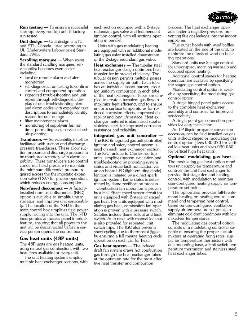
Run testing — To ensure a successful start-up, every rooftop unit is factory run tested.Unit design — Unit design is ETL and ETL, Canada, listed according to UL (Underwriters Laboratories) Stan-dard 1995.Scrolling marquee — When using the standard scrolling marquee, ser-viceability becomes even easier,including:• local or remote alarm and alert
monitoring• self-diagnostic run testing to confirm
control and component operation• expedited troubleshooting and unit
repair through self-diagnostic dis-play of unit troubleshooting alert and alarm codes with expanded text descriptions to immediately identify reason for unit outage
• filter maintenance alarm• monitoring of supply-air fan run
time, permitting easy service sched-ule planning
Tranducers — Serviceability is further facilitated with suction and discharge pressure transducers. These allow suc-tion pressure and discharge pressure to be monitored remotely with alarm ca-pability. These transducers also control condenser head pressure to maintain the minimum differential pressure re-quired across the thermostatic expan-sion valve (TXV) for proper operation, which reduces energy consumption.Non-fused disconnect — A factory-installed non-fused disconnect (NFD) option is available to simplify unit in-stallation and improve unit serviceabili-ty. The location of the NFD in the main control box simplifies field power supply routing into the unit. The NFD incorporates an access panel interlock feature, ensuring that all power to the unit will be disconnected before a ser-vice person opens the control box.
Gas heat units (48P units)The 48P units are gas heating units, using natural gas combustion, with two heat sizes available for every unit.
The unit heating systems employ multiple heat exchanger sections, with
each section equipped with a 2-stage redundant gas valve and independent ignition control, with all sections oper-ating in parallel. Units with gas modulating heating are equipped with an additional modu-lating gas valve installed downstream of the 2-stage redundant gas valve.Heat exchanger — The tubular steel heat exchanger design optimizes heat transfer for improved efficiency. The tubular design permits multiple passes across the supply air path. Each tube has an individual inshot burner, ensur-ing uniform combustion in each tube of the heat exchangers. Tubes are dim-pled to create a turbulent gas flow to maximize heat efficiency and to ensure uniform surface temperatures for re-duced corrosion effects, improved du-rability and long-life service. Heat ex-changer material is aluminized steel or stainless steel, for improved corrosion resistance and reliability.Integrated gas unit controller —The IGC (integrated gas unit controller) ignition and safety control system is used on each heat exchanger section. The IGC, unique to Carrier rooftop units, simplifies system evaluation and troubleshooting by providing system status and visual fault notification via an on-board LED (light-emitting diode). Ignition is initiated by a direct spark ignition system; flame status is deter-mined by flame rectification process. Combustion fan operation is proven by a Hall Effect speed sensor circuit for units equipped with 2-stage or staged gas heat. For units equipped with mod-ulating gas heat, combustion fan oper-ation is proven with a pressure switch. Safeties include flame rollout and limit switch. Auto reset with manual lockout is also provided for repeated limit switch trips. The IGC also prevents short-cycling due to thermostat jiggle by ensuring a full minute heating cycle operation on each call for heat.Gas heat system — The induced draft fan system draws hot combustion gas through the heat exchanger tubes at the optimum rate for the most effec-tive heat transfer and combustion
process. The heat exchanger oper-ates under a negative pressure, pre-venting flue gas leakage into the indoor supply air.
Flue outlet hoods with wind baffles are located on the side of the unit, to minimize the effects of wind on heat-ing operations.
Standard units use 2-stage control, for unoccupied, morning warm-up and occupied space heating.
Additional control stages for heating operation are available by specifying the staged gas control option.
Modulating control option is avail-able by specifying the modulating gas control option.
A single hinged panel gains access to the complete heat exchanger assembly and controls, for improved serviceability.
A single point gas connection pro-vides for easy installation.
An LP (liquid propane) conversion accessory can be field-installed on gas units without staged or modulating gas control option (sizes 030-070 for verti-cal low heat units and sizes 030-050 for vertical high heat units).Optional modulating gas heat —The modulating gas heat option moni-tors unit supply-air temperature and controls the unit heat exchanger to provide first-stage demand heating control, with modulation to maintain user-configured heating supply air tem-perature set point.
The option also provides full-fire de-mand heating on heating control com-mand and tempering heat control, based on user-configured ventilation supply air temperature set point, to eliminate cold draft conditions with low mixed-air temperatures.
The modulating gas control option consists of a modulating controller ca-pable of ensuring the proper fuel air mixture at operating firing rates, sup-ply air temperature thermistors with duct-mounting base, a limit switch tem-perature thermistor, and stainless steel heat exchanger tubes.
6
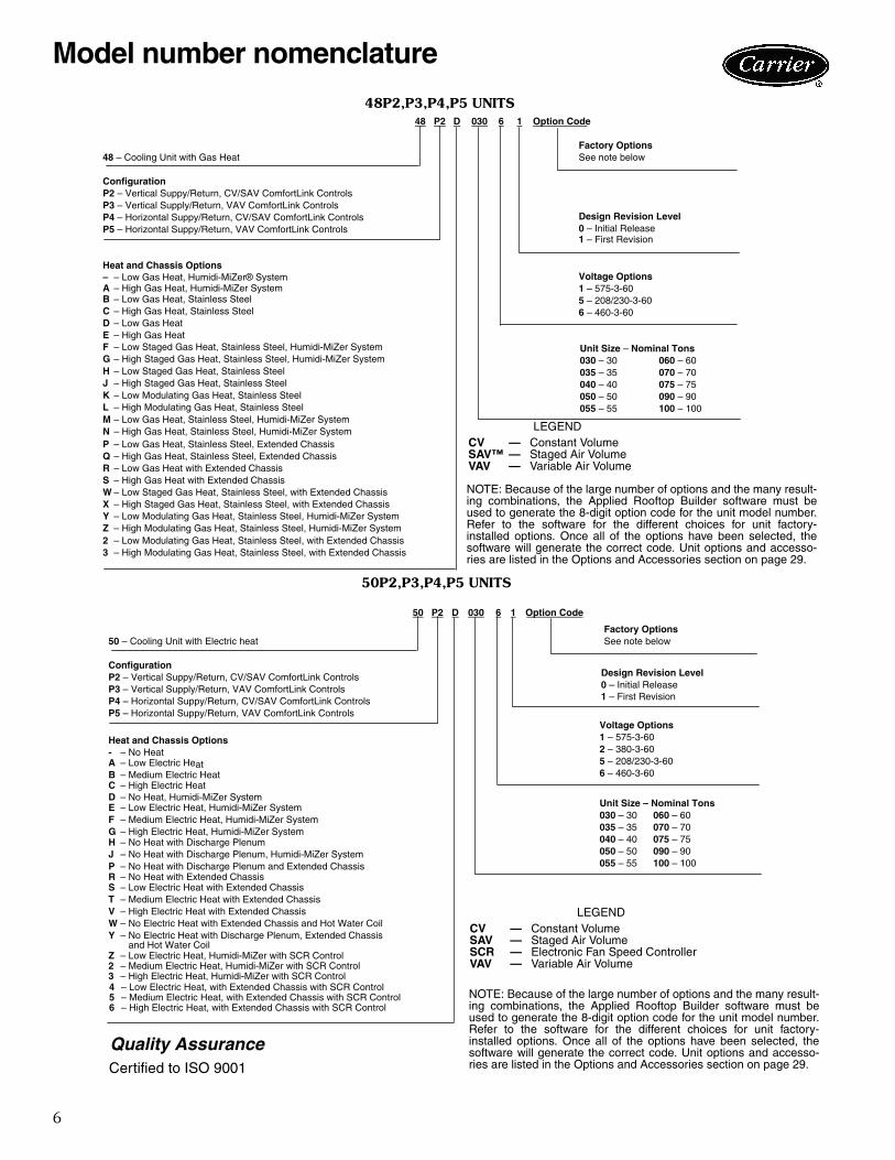
48 P2 D 030 6 1 Option Code
Factory Options48 – Cooling Unit with Gas Heat See note below
P – Low Gas Heat, Stainless Steel, Extended ChassisQ – High Gas Heat, Stainless Steel, Extended ChassisR – Low Gas Heat with Extended ChassisS – High Gas Heat with Extended ChassisW – Low Staged Gas Heat, Stainless Steel, with Extended ChassisX – High Staged Gas Heat, Stainless Steel, with Extended Chassis
– – Low Gas Heat, Humidi-MiZer® System A – High Gas Heat, Humidi-MiZer System
F – Low Staged Gas Heat, Stainless Steel, Humidi-MiZer SystemG – High Staged Gas Heat, Stainless Steel, Humidi-MiZer System
M – Low Gas Heat, Stainless Steel, Humidi-MiZer SystemN – High Gas Heat, Stainless Steel, Humidi-MiZer System
K – Low Modulating Gas Heat, Stainless SteelL – High Modulating Gas Heat, Stainless Steel
Y – Low Modulating Gas Heat, Stainless Steel, Humidi-MiZer SystemZ – High Modulating Gas Heat, Stainless Steel, Humidi-MiZer System2 – Low Modulating Gas Heat, Stainless Steel, with Extended Chassis3 – High Modulating Gas Heat, Stainless Steel, with Extended Chassis
1 – First Revision
50 P2 D 030 6 1 Option Code
Factory Options50 – Cooling Unit with Electric heat See note below
J – No Heat with Discharge Plenum, Humidi-MiZer System 050 – 50 090 – 90055 – 55 100 – 100P – No Heat with Discharge Plenum and Extended Chassis
R – No Heat with Extended ChassisS – Low Electric Heat with Extended ChassisT – Medium Electric Heat with Extended ChassisV – High Electric Heat with Extended ChassisW – No Electric Heat with Extended Chassis and Hot Water CoilY – No Electric Heat with Discharge Plenum, Extended Chassis
and Hot Water Coil
D – No Heat, Humidi-MiZer SystemE – Low Electric Heat, Humidi-MiZer SystemF – Medium Electric Heat, Humidi-MiZer SystemG – High Electric Heat, Humidi-MiZer SystemH – No Heat with Discharge Plenum
1 – First Revision
Z – Low Electric Heat, Humidi-MiZer with SCR Control2 – Medium Electric Heat, Humidi-MiZer with SCR Control3 – High Electric Heat, Humidi-MiZer with SCR Control4 – Low Electric Heat, with Extended Chassis with SCR Control5 – Medium Electric Heat, with Extended Chassis with SCR Control6 – High Electric Heat, with Extended Chassis with SCR Control
NOTE: Because of the large number of options and the many result-ing combinations, the Applied Rooftop Builder software must beused to generate the 8-digit option code for the unit model number.Refer to the software for the different choices for unit factory-installed options. Once all of the options have been selected, thesoftware will generate the correct code. Unit options and accesso-ries are listed in the Options and Accessories section on page 29.
NOTE: Because of the large number of options and the many result-ing combinations, the Applied Rooftop Builder software must beused to generate the 8-digit option code for the unit model number.Refer to the software for the different choices for unit factory-installed options. Once all of the options have been selected, thesoftware will generate the correct code. Unit options and accesso-ries are listed in the Options and Accessories section on page 29.
50P2,P3,P4,P5 UNITS
48P2,P3,P4,P5 UNITSa48-8637
a50-8722
LEGENDCV — Constant VolumeSAV™ — Staged Air VolumeVAV — Variable Air Volume
LEGENDCV — Constant VolumeSAV — Staged Air VolumeSCR — Electronic Fan Speed ControllerVAV — Variable Air Volume
Quality AssuranceCertified to ISO 9001
Model number nomenclature
7
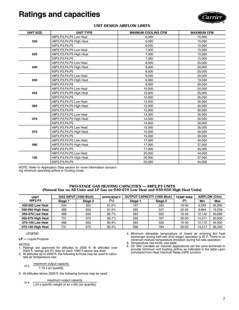
UNIT DESIGN AIRFLOW LIMITS
NOTE: Refer to Application Data section for more information concern-ing minimum operating airflow in Cooling mode.
TWO-STAGE GAS HEATING CAPACITIES — 48P2,P3 UNITS(Natural Gas on All Units and LP Gas on 030-070 Low Heat and 030-050 High Heat Units)
LEGEND
LP — Liquid Propane
NOTES:1. Ratings are approved for altitudes to 2000 ft. At altitudes over
2000 ft, ratings are 4% less for each 1000 ft above sea level.2. At altitudes up to 2000 ft, the following formula may be used to calcu-
late air temperature rise:
3. At altitudes above 2000 ft, the following formula may be used:
4. Minimum allowable temperature of mixed air entering the heatexchanger during half-rate (first stage) operation is 35 F. There is nominimum mixture temperature limitation during full-rate operation.
5. Temperature rise limits: see table.6. On VAV (variable air volume) applications set the zone terminals to
provide minimum unit heating airflow as indicated in the table uponcommand from Heat Interlock Relay (HIR) function.
UNIT SIZE UNIT TYPE MINIMUM COOLING CFM MAXIMUM CFM
(.24 x specific weight of air x 60) (air quantity)
Ratings and capacities
8
TWO-STAGE GAS HEATING CAPACITIES — 48P4,P5 UNITS(Natural Gas on All Units and LP Gas Not Available)
LEGEND
LP — Liquid Propane
NOTES:1. Ratings are approved for altitudes to 2000 ft. At altitudes over
2000 ft, ratings are 4% less for each 1000 ft above sea level.2. At altitudes up to 2000 ft, the following formula may be used to calcu-
late air temperature rise:
3. At altitudes above 2000 ft, the following formula may be used:
4. Minimum allowable temperature of mixed air entering the heatexchanger during half-rate (first stage) operation is 35 F. There is nominimum mixture temperature limitation during full-rate operation.
5. Temperature rise limits: see table.6. On VAV (variable air volume) applications set the zone terminals to
provide minimum unit heating airflow as indicated in the table uponcommand from Heat Interlock Relay (HIR) function.
GAS HEATING CAPACITIES — UNITS WITH STAGED GAS CONTROL OPTION
48P2,P3 030-050 LOW HEAT
48P4,P5 030-050 LOW HEAT
48P2,P3 030-050 HIGH HEAT
48P4,P5 030-050 HIGH HEAT
UNIT48P4,P5
GAS INPUT (1000 Btuh) EFFICIENCY(%)
OUTPUT CAPACITY (1000 Btuh) TEMP RISE(F)
AIRFLOW (Cfm)Stage 1 Stage 2 Stage 1 Stage 2 Min Max
GAS HEATING CAPACITIES — UNITS WITH MODULATING GAS CONTROL OPTION (cont)
48P2,P3 075-100 HIGH HEAT
48P4,P5 075-100 HIGH HEAT
LEGEND
HF — High FireLF — Low Fire
ELECTRIC HEATER CAPACITIES
NOTES:1. Electric heat options are NOT AVAILABLE on discharge plenum units or size 030-070 horizontal units.2. Electric heat is available on horizontal size 075-100 units with airfoil fan option only.
* 460-3-60 only.†See Power Exhaust Fan Drive Data table on page 28 for more information.
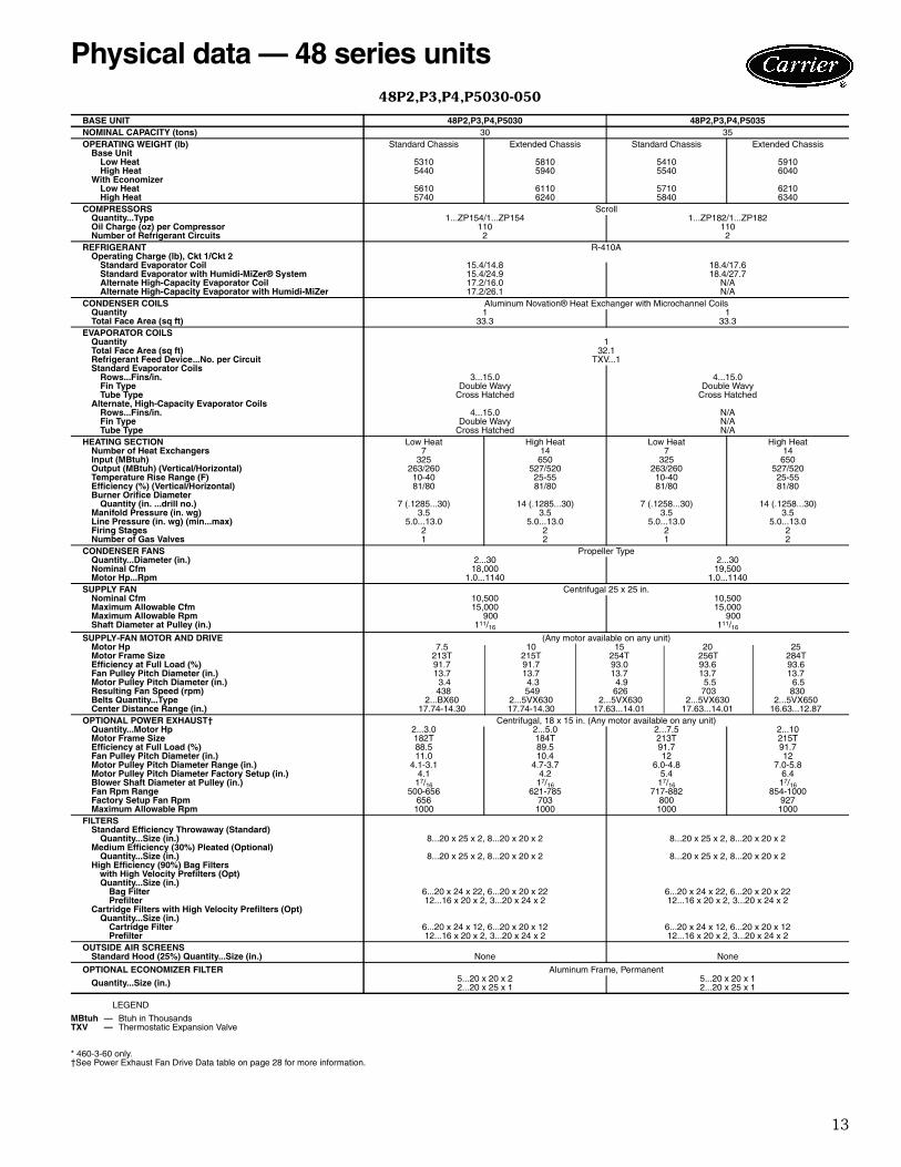
BASE UNIT 48P2,P3,P4,P5030 48P2,P3,P4,P5035NOMINAL CAPACITY (tons) 30 35OPERATING WEIGHT (lb) Standard Chassis Extended Chassis Standard Chassis Extended Chassis
SUPPLY FAN Centrifugal 25 x 25 in.Nominal Cfm 10,500 10,500Maximum Allowable Cfm 15,000 15,000Maximum Allowable Rpm 900 900Shaft Diameter at Pulley (in.) 111/16 111/16
SUPPLY-FAN MOTOR AND DRIVE (Any motor available on any unit)Motor Hp 7.5 10 15 20 25Motor Frame Size 213T 215T 254T 256T 284TEfficiency at Full Load (%) 91.7 91.7 93.0 93.6 93.6Fan Pulley Pitch Diameter (in.) 13.7 13.7 13.7 13.7 13.7Motor Pulley Pitch Diameter (in.) 3.4 4.3 4.9 5.5 6.5Resulting Fan Speed (rpm) 438 549 626 703 830 Belts Quantity...Type 2...BX60 2...5VX630 2...5VX630 2...5VX630 2...5VX650Center Distance Range (in.) 17.74-14.30 17.74-14.30 17.63...14.01 17.63...14.01 16.63...12.87
OPTIONAL POWER EXHAUST† Centrifugal, 18 x 15 in. (Any motor available on any unit)Quantity...Motor Hp 2...3.0 2...5.0 2...7.5 2...10Motor Frame Size 182T 184T 213T 215TEfficiency at Full Load (%) 88.5 89.5 91.7 91.7Fan Pulley Pitch Diameter (in.) 11.0 10.4 12 12Motor Pulley Pitch Diameter Range (in.) 4.1-3.1 4.7-3.7 6.0-4.8 7.0-5.8Motor Pulley Pitch Diameter Factory Setup (in.) 4.1 4.2 5.4 6.4Blower Shaft Diameter at Pulley (in.) 17/16 17/16 17/16 17/16Fan Rpm Range 500-656 621-785 717-882 854-1000Factory Setup Fan Rpm 656 703 800 927Maximum Allowable Rpm 1000 1000 1000 1000
FILTERSStandard Efficiency Throwaway (Standard)
Quantity...Size (in.) 8...20 x 25 x 2, 8...20 x 20 x 2 8...20 x 25 x 2, 8...20 x 20 x 2Medium Efficiency (30%) Pleated (Optional)
Quantity...Size (in.) 8...20 x 25 x 2, 8...20 x 20 x 2 8...20 x 25 x 2, 8...20 x 20 x 2High Efficiency (90%) Bag Filters
with High Velocity Prefilters (Opt)Quantity...Size (in.)
Bag Filter 6...20 x 24 x 22, 6...20 x 20 x 22 6...20 x 24 x 22, 6...20 x 20 x 22Prefilter 12...16 x 20 x 2, 3...20 x 24 x 2 12...16 x 20 x 2, 3...20 x 24 x 2
Cartridge Filters with High Velocity Prefilters (Opt)Quantity...Size (in.)
Cartridge Filter 6...20 x 24 x 12, 6...20 x 20 x 12 6...20 x 24 x 12, 6...20 x 20 x 12Prefilter 12...16 x 20 x 2, 3...20 x 24 x 2 12...16 x 20 x 2, 3...20 x 24 x 2
OUTSIDE AIR SCREENSStandard Hood (25%) Quantity...Size (in.) None None
Quantity...Size (in.) 5...20 x 20 x 22...20 x 25 x 1
5...20 x 20 x 12...20 x 25 x 1
MBtuh — Btuh in ThousandsTXV — Thermostatic Expansion Valve
Physical data — 48 series units
14
48P2,P3,P4,P5030-050 (cont)
LEGEND
* 460-3-60 only.†See Power Exhaust Fan Drive Data table on page 28 for more information.
BASE UNIT 48P2,P3,P4,P5040 48P2,P3,P4,P5050NOMINAL CAPACITY (tons) 40 50OPERATING WEIGHT (lb) Standard Chassis Extended Chassis Standard Chassis Extended Chassis
SUPPLY FAN Centrifugal 25 x 25 in.Nominal Cfm 14,000 14,000Maximum Allowable Cfm 20,000 20,000Maximum Allowable Rpm 900 900Shaft Diameter at Pulley (in.) 111/16 111/16
SUPPLY-FAN MOTOR AND DRIVE (Any motor available on any unit)Motor Hp 7.5 10 15 20 25 30*Motor Frame Size 213T 215T 254T 256T 284T 286TEfficiency at Full Load (%) 91.7 91.7 93.0 93.6 93.6 93.6Fan Pulley Pitch Diameter (in.) 13.7 13.7 13.7 13.7 13.7 12.5Motor Pulley Pitch Diameter (in.) 3.4 4.3 4.9 5.5 6.5 6.5Resulting Fan Speed (rpm) 438 549 626 703 830 910Belts Quantity...Type 2...BX60 2...5VX630 2...5VX630 2...5VX630 2...5VX650 3...5VX630Center Distance Range (in.) 17.74-14.30 17.74-14.30 17.63...14.01 17.63...14.01 16.63...12.87 16.63...12.87
OPTIONAL POWER EXHAUST† Centrifugal, 18 x 15 in. (Any motor available on any unit)Quantity...Motor Hp 2...3.0 2...5.0 2...7.5 2...10Motor Frame Size 182T 184T 213T 215TEfficiency at Full Load (%) 88.5 89.5 91.7 91.7Fan Pulley Pitch Diameter (in.) 11.0 10.4 12 12Motor Pulley Pitch Diameter Range (in.) 4.1-3.1 4.7-3.7 6.0-4.8 7.0-5.8Motor Pulley Pitch Diameter Factory Setup (in.) 4.1 4.2 5.4 6.4Blower Shaft Diameter at Pulley (in.) 17/16 17/16 17/16 17/16Fan Rpm Range 500-656 621-785 717-882 854-1000Factory Setup Fan Rpm 656 703 800 927Maximum Allowable Rpm 1000 1000 1000 1000
FILTERSStandard Efficiency Throwaway (Standard)
Quantity...Size (in.) 8...20 x 25 x 2, 8...20 x 20 x 2 8...20 x 25 x 2, 8...20 x 20 x 2Medium Efficiency (30%) Pleated (Optional)
Quantity...Size (in.) 8...20 x 25 x 2, 8...20 x 20 x 2 8...20 x 25 x 2, 8...20 x 20 x 2High Efficiency (90%) Bag Filters
with High Velocity Prefilters (Opt)Quantity...Size (in.)
Bag Filter 6...20 x 24 x 22, 6...20 x 20 x 22 6...20 x 24 x 22, 6...20 x 20 x 22Prefilter 12...16 x 20 x 2, 3...20 x 24 x 2 12...16 x 20 x 2, 3...20 x 24 x 2
Cartridge Filters with High Velocity Prefilters (Opt)Quantity...Size (in.)
Cartridge Filter 6...20 x 24 x 12, 6...20 x 20 x 12 6...20 x 24 x 12, 6...20 x 20 x 12Prefilter 12...16 x 20 x 2, 3...20 x 24 x 2 12...16 x 20 x 2, 3...20 x 24 x 2
OUTSIDE AIR SCREENSStandard Hood (25%) Quantity...Size (in.) None None
Quantity...Size (in.) 5...20 x 20 x 22...20 x 25 x 1
5...20 x 20 x 12...20 x 25 x 1
MBtuh — Btuh in ThousandsTXV — Thermostatic Expansion Valve
Physical data — 48 series units (cont)
15
48P2,P3,P4,P5055-070
LEGEND
*See Power Exhaust Fan Drive Data table on page 28 for more information.
BASE UNIT 48P2,P3,P4,P5055 48P2,P3,P4,P5060 48P2,P3,P4,P5070NOMINAL CAPACITY (tons) 55 60 70OPERATING WEIGHT (lb) Standard Chassis Extended Chassis Standard Chassis Extended Chassis Standard Chassis Extended Chassis
SUPPLY FAN Centrifugal 30 x 27.5 in.Nominal Cfm 17,500 21,000 24,500Maximum Allowable Cfm 25,000 30,000 30,000Maximum Allowable Rpm 800 800 800Shaft Diameter at Pulley (in.) 111/16 111/16 111/16
SUPPLY-FAN MOTOR AND DRIVE (Any motor available on any unit)Motor Hp 15 20 25 30 40Motor Frame Size 254T 256T 284T 286T S324TEfficiency at Full Load (%) 93.0 93.6 93.6 93.6 94.5Fan Pulley Pitch Diameter (in.) 13.7 13.7 13.7 15.5 16.1Motor Pulley Pitch Diameter (in.) 4.5 5.1 5.5 5.9 6.7Resulting Fan Speed (rpm) 575 651 703 711 740Belts Quantity...Type 2...5VX1230 2...5VX1230 2...5VX1230 2...5VX1230 3...5VX1250Center Distance Range (in.) 48.25-44.00 48.25-44.00 48.50-44.25 48.50-44.25 48.25-44.00
OPTIONAL POWER EXHAUST* Centrifugal, 18 x 15 in. (Any motor available on any unit)Quantity...Motor Hp 2...5 2...7.5 2...10Motor Frame Size 184T 213T 215TEfficiency at Full Load (%) 89.5 91.7 91.7Resulting Fan Rpm 740 820 920Maximum Allowable Rpm 1000 1000 1000
FILTERSStandard Efficiency Throwaway (Standard)
Quantity...Size (in.) 12...20 x 25 x 2, 12...20 x 20 x 2 12...20 x 25 x 2, 12...20 x 20 x 2 12...20 x 25 x 2, 12...20 x 20 x 2Medium Efficiency (30%) Pleated (Optional)
Quantity...Size (in.) 12...20 x 25 x 2, 12...20 x 20 x 2 12...20 x 25 x 2, 12...20 x 20 x 2 12...20 x 25 x 2, 12...20 x 20 x 2High Efficiency (90%) Bag Filters
with High Velocity Prefilters (Optional)Quantity...Size (in.)
Bag Filter 6...24 x 24 x 22, 6...24 x 20 x 22 6...24 x 24 x 22, 6...24 x 20 x 22 6...24 x 24 x 22, 6...24 x 20 x 22 Prefilter 6...24 x 24 x 2, 6...20 x 24 x 2 6...24 x 24 x 2, 6...20 x 24 x 2 6...24 x 24 x 2, 6...20 x 24 x 2
Cartridge Filters with High Velocity Prefilters (Optional)
Quantity...Size (in.) Cartridge Filter 6...24 x 24 x 12,, 6...24 x 20 x 12 6...24 x 24 x 12,, 6...24 x 20 x 12 6...24 x 24 x 12, 6...24 x 20 x 12 Prefilter 6...24 x 24 x 2, 6...20 x 24 x 2 6...24 x 24 x 2, 6...20 x 24 x 2 6...24 x 24 x 2, 6...20 x 24 x 2
OUTSIDE AIR SCREENSStandard Hood (25%) Quantity...Size (in.) 4...25 x 16 x 1, 2...20 x 16 x 1 4...25 x 16 x 1, 2...20 x 16 x 1 4...25 x 16 x 1, 2...20 x 16 x 1
OPTIONAL ECONOMIZER FILTER Aluminum Frame, Permanent Quantity...Size (in.) 12...16 x 25 x 1, 2...16 x 20 x 1 12...16 x 25 x 1, 2...16 x 20 x 1 12...16 x 25 x 1, 2...16 x 20 x 1
MBtuh — Btuh in ThousandsTXV — Thermostatic Expansion Valve
16
48P2,P3,P4,P5075-100
LEGEND
*See page 22 for high-capacity power exhaust information. See Power ExhaustFan Drive Data table on page 28 for more information.
BASE UNIT 48P2,P3,P4,P5075 48P2,P3,P4,P5090 48P2,P3,P4,P5100
NOMINAL CAPACITY (tons) 75 90 100OPERATING WEIGHT (lb) Standard
ALTERNATE SUPPLY-FAN MOTOR AND DRIVE (Any motor available on any unit)Motor Hp 30 40 50 60 75Motor Frame Size S268T S324T S36T S364T 365TEfficiency at Full Load (%) 93.6 94.5 94.5 95.4 95.4Fan Pulley Pitch Diameter (in.) 9.7 10.2 8.9 8.9 10.8Motor Pulley Pitch Diameter (in.) 7.5 8.7 8.1 8.7 11.1Resulting Fan Rpm 1353 1493 1593 1711 1799Belts Quantity...Type 2...5VX1150 2...5VX1180 3...5VX1150 3...5VX1150 3...5VX1230Center Distance Range (in.) 42.96...45.82 42.96...45.57 42.96...45.57 42.45...45.35 42.45...45.35
MBtuh — Btuh in ThousandsTXV — Thermostatic Expansion Valve
Physical data — 48 series units (cont)
17
48P2,P3,P4,P5075-100 (cont)
LEGEND
*See page 22 for high-capacity power exhaust information. See Power ExhaustFan Drive Data table on page 28 for more information.
BASE UNIT 48P2,P3,P4,P5075 48P2,P3,P4,P5090 48P2,P3,P4,P5100OPTIONAL POWER EXHAUST* Centrifugal, 18 x 15 in. (Any motor available on any unit.)
Quantity...Motor Hp 2...5 2...7.5 2...10Motor Frame Size 184T 213T 215TEfficiency at Full Load (%) 89.5 91.7 91.7Fan Pulley Pitch Diameter (in.) 10.6 10.6 10.6Motor Pulley Pitch Diameter (in.) 4.5 5.0 5.6Shaft Diameter at Pulley (in.) 17/16 17/16 17/16Resulting Fan Rpm 740 820 920Maximum Allowable Rpm 1000 1000 1000
FILTERSStandard Efficiency Throwaway (Standard)
Quantity...Size (in.) 12...20 x 25 x 2, 12...20 x 20 x 2 12...20 x 25 x 2, 12...20 x 20 x 2 12...20 x 25 x 2, 12...20 x 20 x 230% and 65% Pleated (Optional)
Quantity...Size (in.) 12...20 x 25 x 2, 12...20 x 20 x 2 12...20 x 25 x 2, 12...20 x 20 x 2 12...20 x 25 x 2, 12...20 x 20 x 2
OUTSIDE AIR SCREENSStandard Hood (25%) Quantity...Size (in.) 4...25 x 16 x 1, 2...20 x 16 x 1 4...25 x 16 x 1, 2...20 x 16 x 1 4...25 x 16 x 1, 2...20 x 16 x 1
OPTIONAL ECONOMIZER FILTER Aluminum Frame, PermanentQuantity...Size (in.) 12...16 x 25 x 1, 2...16 x 20 x 1 12...16 x 25 x 1, 2...16 x 20 x 1 12...16 x 25 x 1, 2...16 x 20 x 1
MBtuh — Btuh in ThousandsTXV — Thermostatic Expansion Valve
18
50P2,P3,P4,P5030-050
LEGEND
* 460-3-60 only.†See Power Exhaust Fan Drive Data table on page 28 for more information.
BASE UNIT 50P2,P3,P4,P5030 50P2,P3,P4,P5035NOMINAL CAPACITY (tons) 30 35OPERATING WEIGHT (lb) Standard Chassis Extended Chassis Standard Chassis Extended Chassis
Base UnitVertical Discharge 4810 5310 4910 5410Horizontal Discharge and Vertical Discharge
with Discharge Plenum 5110 5610 5210 5710
With EconomizerVertical Discharge 5110 5610 5210 5710Horizontal Discharge and Vertical Discharge
with Discharge Plenum 5410 5910 5510 6010
COMPRESSORS ScrollQuantity...Type 1...ZP154/1...ZP154 1...ZP182/1...ZP182Oil Charge (oz) per Compressor 110 110Number of Refrigerant Circuits 2 2
SUPPLY FAN Centrifugal 25 x 25 in.Nominal Cfm 10,500 10,500Maximum Allowable Cfm 15,000 15,000Maximum Allowable Rpm 900 900Shaft Diameter at Pulley (in.) 111/16 111/16
SUPPLY-FAN MOTOR AND DRIVE (Any motor available on any unit)Motor Hp 7.5 10 15 20 25Motor Frame Size 213T 215T 254T 256T 284TEfficiency at Full Load (%) 91.7 91.7 93.0 93.6 93.6Fan Pulley Pitch Diameter (in.) 13.7 13.7 13.7 13.7 13.7Motor Pulley Pitch Diameter (in.) 3.4 4.3 4.9 5.5 6.5Resulting Fan Speed (rpm) 438 549 626 703 830 Belts Quantity...Type 2...BX60 2...5VX630 2...5VX630 2...5VX630 2...5VX650Center Distance Range (in.) 17.74-14.30 17.74-14.30 17.63...14.01 17.63...14.01 16.63...12.87
OPTIONAL POWER EXHAUST† Centrifugal, 18 x 15 in. (Any motor available on any unit)Quantity...Motor Hp 2...3.0 2...5.0 2...7.5 2...10Motor Frame Size 182T 184T 213T 215TEfficiency at Full Load (%) 88.5 89.5 91.7 91.7Fan Pulley Pitch Diameter (in.) 11.0 10.4 12 12Motor Pulley Pitch Diameter Range (in.) 4.1-3.1 4.7-3.7 6.0-4.8 7.0-5.8Motor Pulley Pitch Diameter Factory Setup (in.) 4.1 4.2 5.4 6.4Blower Shaft Diameter at Pulley (in.) 17/16 17/16 17/16 17/16Fan Rpm Range 500-656 621-785 717-882 854-1000Factory Setup Fan Rpm 656 703 800 927Maximum Allowable Rpm 1000 1000 1000 1000
FILTERSStandard Efficiency Throwaway (Standard)
Quantity...Size (in.) 8...20 x 25 x 2, 8...20 x 20 x 2 8...20 x 25 x 2, 8...20 x 20 x 2Medium Efficiency (30%) Pleated (Optional)
Quantity...Size (in.) 8...20 x 25 x 2, 8...20 x 20 x 2 8...20 x 25 x 2, 8...20 x 20 x 2High Efficiency (90%) Bag Filters
with High Velocity Prefilters (Opt)Quantity...Size (in.)
Bag Filter 6...20 x 24 x 22, 6...20 x 20 x 22 6...20 x 24 x 22, 6...20 x 20 x 22Prefilter 12...16 x 20 x 2, 3...20 x 24 x 2 12...16 x 20 x 2, 3...20 x 24 x 2
Cartridge Filters with High Velocity Prefilters (Opt)Quantity...Size (in.)
Cartridge Filter 6...20 x 24 x 12, 6...20 x 20 x 12 6...20 x 24 x 12, 6...20 x 20 x 12Prefilter 12...16 x 20 x 2, 3...20 x 24 x 2 12...16 x 20 x 2, 3...20 x 24 x 2
OUTSIDE AIR SCREENSStandard Hood (25%) Quantity...Size (in.) None None
OPTIONAL ECONOMIZER FILTER Aluminum Frame, PermanentQuantity...Size (in.) 5...20 x 20 x 2, 2...20 x 25 x 1 5...20 x 20 x 1, 2...20 x 25 x 1
TXV — Thermostatic Expansion Valve
Physical data — 50 series units
19
50P2,P3,P4,P5030-050 (cont)
LEGEND
* 460-3-60 only.†See Power Exhaust Fan Drive Data table on page 28 for more information.
BASE UNIT 50P2,P3,P4,P5040 50P2,P3,P4,P5050NOMINAL CAPACITY (tons) 40 50OPERATING WEIGHT (lb) Standard Chassis Extended Chassis Standard Chassis Extended Chassis
Base UnitVertical Discharge 5310 5810 5525 6025Horizontal Discharge and Vertical Discharge
with Discharge Plenum 5610 6110 5825 6325
With EconomizerVertical Discharge 5610 6110 5825 6325Horizontal Discharge and Vertical Discharge
with Discharge Plenum 5910 6410 6125 6625
COMPRESSORS ScrollQuantity...Type 2...ZP103/1...ZP182 2...ZP120/2...ZP137Oil Charge (oz) per Compressor 110 110Number of Refrigerant Circuits 2 2
SUPPLY FAN Centrifugal 25 x 25 in.Nominal Cfm 14,000 14,000Maximum Allowable Cfm 20,000 20,000Maximum Allowable Rpm 900 900Shaft Diameter at Pulley (in.) 111/16 111/16
SUPPLY-FAN MOTOR AND DRIVE (Any motor available on any unit)Motor Hp 7.5 10 15 20 25 30*Motor Frame Size 213T 215T 254T 256T 284T 286TEfficiency at Full Load (%) 91.7 91.7 93.0 93.6 93.6 93.6Fan Pulley Pitch Diameter (in.) 13.7 13.7 13.7 13.7 13.7 12.5Motor Pulley Pitch Diameter (in.) 3.4 4.3 4.9 5.5 6.5 6.5Resulting Fan Speed (rpm) 438 549 626 703 830 910Belts Quantity...Type 2...BX60 2...5VX630 2...5VX630 2...5VX630 2...5VX650 3...5VX630Center Distance Range (in.) 17.74-14.30 17.74-14.30 17.63...14.01 17.63...14.01 16.63...12.87 16.63...12.87
OPTIONAL POWER EXHAUST† Centrifugal, 18 x 15 in. (Any motor available on any unit)Quantity...Motor Hp 2...3.0 2...5.0 2...7.5 2...10Motor Frame Size 182T 184T 213T 215TEfficiency at Full Load (%) 88.5 89.5 91.7 91.7Fan Pulley Pitch Diameter (in.) 11.0 10.4 12 12Motor Pulley Pitch Diameter Range (in.) 4.1-3.1 4.7-3.7 6.0-4.8 7.0-5.8Motor Pulley Pitch Diameter Factory Setup (in.) 4.1 4.2 5.4 6.4Blower Shaft Diameter at Pulley (in.) 17/16 17/16 17/16 17/16Fan Rpm Range 500-656 621-785 717-882 854-1000Factory Setup Fan Rpm 656 703 800 927Maximum Allowable Rpm 1000 1000 1000 1000
FILTERSStandard Efficiency Throwaway (Standard)
Quantity...Size (in.) 8...20 x 25 x 2, 8...20 x 20 x 2 8...20 x 25 x 2, 8...20 x 20 x 2Medium Efficiency (30%) Pleated (Optional)
Quantity...Size (in.) 8...20 x 25 x 2, 8...20 x 20 x 2 8...20 x 25 x 2, 8...20 x 20 x 2High Efficiency (90%) Bag Filters with High Velocity
Prefilters (Optional)Quantity...Size (in.)
Bag Filter 6...20 x 24 x 22, 6...20 x 20 x 22 6...20 x 24 x 22, 6...20 x 20 x 22Prefilter 12...16 x 20 x 2, 3...20 x 24 x 2 12...16 x 20 x 2, 3...20 x 24 x 2
Cartridge Filters with High Velocity Prefilters (Opt)Quantity...Size (in.)
Cartridge Filter 6...20 x 24 x 12, 6...20 x 20 x 12 6...20 x 24 x 12, 6...20 x 20 x 12Prefilter 12...16 x 20 x 2, 3...20 x 24 x 2 12...16 x 20 x 2, 3...20 x 24 x 2
OUTSIDE AIR SCREENSStandard Hood (25%) Quantity...Size (in.) None None
OPTIONAL ECONOMIZER FILTER Aluminum Frame, PermanentQuantity...Size (in.) 5...20 x 20 x 2, 2...20 x 25 x 1 5...20 x 20 x 1, 2...20 x 25 x 1
TXV — Thermostatic Expansion Valve
20
50P2,P3,P4,P5055-070
LEGEND
* 460-3-60 and 575-3-60 only.†See Power Exhaust Fan Drive Data table on page 28 for more information.
BASE UNIT 50P2,P3,P4,P5055 50P2,P3,P4,P5060 50P2,P3,P4,P5070NOMINAL CAPACITY (tons) 55 60 70OPERATING WEIGHT (lb) Standard Chassis Extended Chassis Standard Chassis Extended Chassis Standard Chassis Extended Chassis
Base UnitVertical Discharge 6820 7370 6875 7425 7215 7765Horizontal Discharge and Vertical Discharge
with Discharge Plenum 7370 7920 7425 7975 7765 8315
With EconomizerVertical Discharge 7350 7900 7405 7955 7745 8295Horizontal Discharge and Vertical Discharge
with Discharge Plenum 7900 8450 7955 8505 8295 8845
COMPRESSORS ScrollQuantity...Type 2...ZP137/2...ZP137 2...ZP154/2...ZP154 1...ZP154,1...ZP182/1...ZP154,1...ZP182Oil Charge (oz) per Compressor 110 110 110Number of Refrigerant Circuits 2 2 2
SUPPLY FAN Centrifugal 30 x 27.5 in.Nominal Cfm 17,500 21,000 24,500Maximum Allowable Cfm 25,000 30,000 30,000Maximum Allowable Rpm 800 800 800Shaft Diameter at Pulley (in.) 111/16 111/16 111/16
SUPPLY-FAN MOTOR AND DRIVE (Any motor available on any unit)Motor Hp 15 20 25 30 40*Motor Frame Size 254T 256T 284T 286T S324TEfficiency at Full Load (%) 93.0 93.6 93.6 93.6 94.5Fan Pulley Pitch Diameter (in.) 13.7 13.7 13.7 15.5 16.1Motor Pulley Pitch Diameter (in.) 4.5 5.1 5.5 5.9 6.7Resulting Fan Speed (rpm) 575 651 703 711 740Belts Quantity...Type 2...5VX1230 2...5VX1230 2...5VX1230 2...5VX1230 3...5VX1250Center Distance Range (in.) 48.25-44.00 48.25-44.00 48.50-44.25 48.50-44.25 48.25-44.00
OPTIONAL POWER EXHAUST† Centrifugal, 18 x 15 in. (Any motor available on any unit)Quantity...Motor Hp 2...5 2...7.5 2...10Motor Frame Size 184T 213T 215TEfficiency at Full Load (%) 89.5 91.7 91.7Resulting Fan Rpm 740 820 920Maximum Allowable Rpm 1000 1000 1000
FILTERSStandard Efficiency Throwaway (Standard)
Quantity...Size (in.) 12...20 x 25 x 2, 12...20 x 20 x 2 12...20 x 25 x 2, 12...20 x 20 x 2 12...20 x 25 x 2, 12...20 x 20 x 2Medium Efficiency (30%) Pleated (Optional)
Quantity...Size (in.) 12...20 x 25 x 2, 12...20 x 20 x 2 12...20 x 25 x 2, 12...20 x 20 x 2 12...20 x 25 x 2, 12...20 x 20 x 2High Efficiency (90%) Bag Filters
with High Velocity Prefilters (Optional)Quantity...Size (in.)
Bag Filter 6...24 x 24 x 22, 6...24 x 20 x 22 6...24 x 24 x 22, 6...24 x 20 x 22 6...24 x 24 x 22, 6...24 x 20 x 22 Prefilter 6...24 x 24 x 2, 6...20 x 24 x 2 6...24 x 24 x 2, 6...20 x 24 x 2 6...24 x 24 x 2, 6...20 x 24 x 2
Cartridge Filters with High Velocity Prefilters (optional)
Quantity...Size (in.) Cartridge Filter 6...24 x 24 x 12,, 6...24 x 20 x 12 6...24 x 24 x 12, 6...24 x 20 x 12 6...24 x 24 x 12, 6...24 x 20 x 12 Prefilter 6...24 x 24 x 2, 6...20 x 24 x 2 6...24 x 24 x 2, 6...20 x 24 x 2 6...24 x 24 x 2, 6...20 x 24 x 2
OUTSIDE AIR SCREENS
Standard Hood (25%) Quantity...Size (in.) 4...25 x 16 x 12...20 x 16 x 1
ALTERNATE SUPPLY-FAN MOTOR AND DRIVE (Any motor available on any unit)Motor Hp 30 40 50 60 75Motor Frame Size S268T S324T S36T S364T 365TEfficiency at Full Load (%) 93.6 94.5 94.5 95.4 95.4Fan Pulley Pitch Diameter (in.) 9.7 10.2 8.9 8.9 10.8Motor Pulley Pitch Diameter (in.) 7.5 8.7 8.1 8.7 11.1Resulting Fan Rpm 1353 1493 1593 1711 1799Belts Quantity...Type 2...5VX1150 2...5VX1180 3...5VX1150 3...5VX1150 3...5VX1230Center Distance Range (in.) 42.96...45.82 42.96...45.57 42.96...45.57 42.45...45.35 42.45...45.35
OPTIONAL POWER EXHAUST* Centrifugal, 18 x 15 in. (Any motor available on any unit.)Quantity...Motor Hp 2...5 2...7.5 2...10Motor Frame Size 184T 213T 215TEfficiency at Full Load (%) 89.5 91.7 91.7Fan Pulley Pitch Diameter (in.) 10.6 10.6 10.6Motor Pulley Pitch Diameter (in.) 4.5 5.0 5.6Shaft Diameter at Pulley (in.) 17/16 17/16 17/16Resulting Fan Rpm 740 820 920Maximum Allowable Rpm 1000 1000 1000
FILTERSStandard Efficiency Throwaway (Standard) 12...20 x 25 x 2 12...20 x 25 x 2 12...20 x 25 x 2
Quantity...Size (in.) 12...20 x 20 x 2 12...20 x 20 x 2 12...20 x 20 x 230% and 65% Pleated (Optional) 12...20 x 25 x 2 12...20 x 25 x 2 12...20 x 25 x 2
Quantity...Size (in.) 12...20 x 20 x 2 12...20 x 20 x 2 12...20 x 20 x 2
OUTSIDE AIR SCREENS
Standard Hood (25%) Quantity...Size (in.) 4...25 x 16 x 12...20 x 16 x 1
Quantity...Size (in.) 12...16 x 25 x 12...16 x 20 x 1
12...16 x 25 x 12...16 x 20 x 1
12...16 x 25 x 12...16 x 20 x 1
TXV — Thermostatic Expansion Valve
22
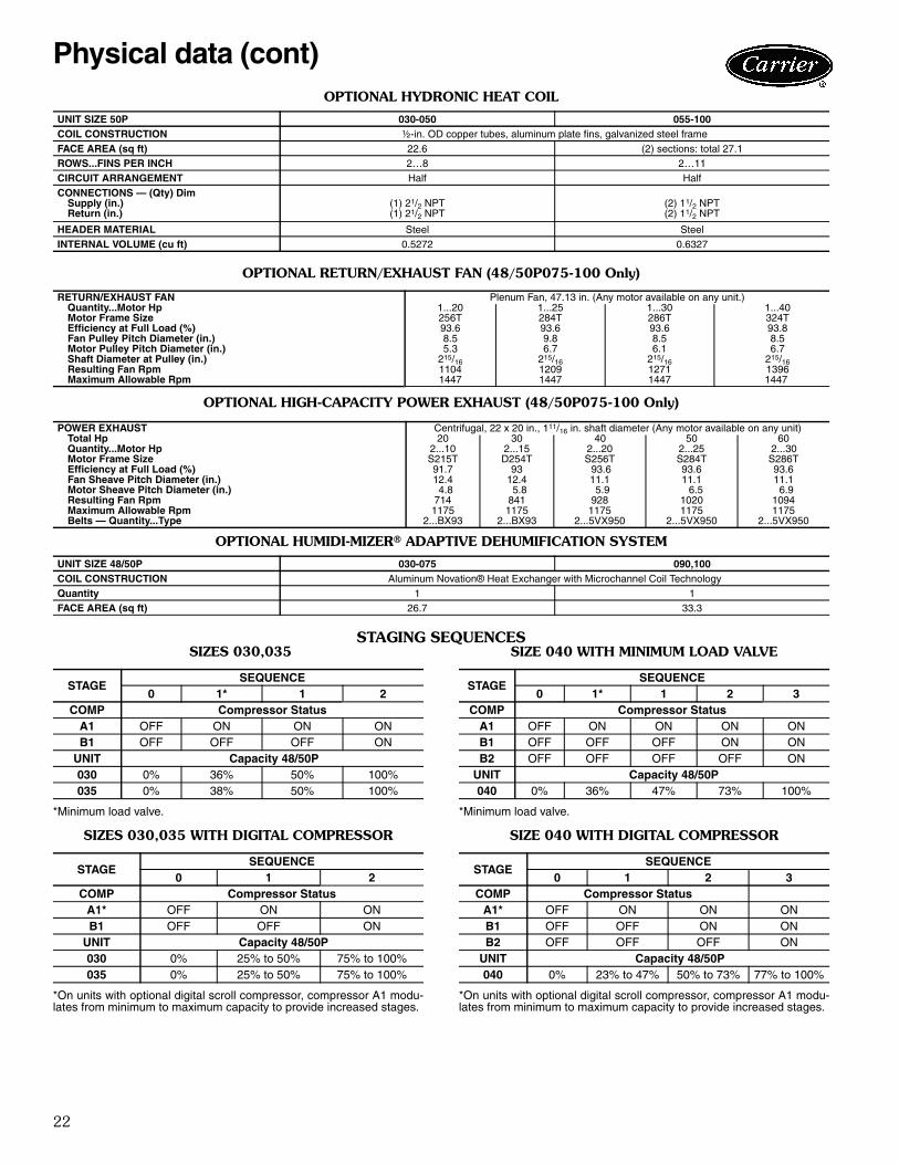
OPTIONAL HYDRONIC HEAT COIL
OPTIONAL RETURN/EXHAUST FAN (48/50P075-100 Only)
OPTIONAL HIGH-CAPACITY POWER EXHAUST (48/50P075-100 Only)
OPTIONAL HUMIDI-MIZER® ADAPTIVE DEHUMIFICATION SYSTEM
STAGING SEQUENCES SIZES 030,035
*Minimum load valve.
SIZES 030,035 WITH DIGITAL COMPRESSOR
*On units with optional digital scroll compressor, compressor A1 modu-lates from minimum to maximum capacity to provide increased stages.
SIZE 040 WITH MINIMUM LOAD VALVE
*Minimum load valve.
SIZE 040 WITH DIGITAL COMPRESSOR
*On units with optional digital scroll compressor, compressor A1 modu-lates from minimum to maximum capacity to provide increased stages.
UNIT SIZE 50P 030-050 055-100COIL CONSTRUCTION ½-in. OD copper tubes, aluminum plate fins, galvanized steel frameFACE AREA (sq ft) 22.6 (2) sections: total 27.1ROWS...FINS PER INCH 2…8 2…11CIRCUIT ARRANGEMENT Half HalfCONNECTIONS — (Qty) Dim
A1* OFF ON ON ON ONA2 OFF OFF OFF ON ONB1 OFF OFF ON ON ONB2 OFF OFF OFF OFF ON
UNIT Capacity 48/50P050 0% 12% to 23% 38% to 50% 62% to 73% 88% to 100%055 0% 13% to 25% 38% to 50% 63% to 75% 88% to 100%060 0% 13% to 25% 38% to 50% 63% to 75% 88% to 100%070 0% 11% to 23% 34% to 46% 61% to 73% 89% to 100%075 0% 13% to 25% 38% to 50% 63% to 75% 88% to 100%
STAGESEQUENCE
0 1* 1 2 3 4 5 6COMP Compressor Status
A1 OFF ON ON ON ON ON ON ONA2 OFF OFF OFF OFF ON ON ON ONA3 OFF OFF OFF OFF OFF OFF ON ONB1 OFF OFF OFF ON ON ON ON ONB2 OFF OFF OFF OFF OFF ON ON ONB3 OFF OFF OFF OFF OFF OFF OFF ON
A1* OFF ON ON ON ON ON ONA2 OFF OFF OFF ON ON ON ONA3 OFF OFF OFF OFF OFF ON ONB1 OFF OFF ON ON ON ON ONB2 OFF OFF OFF OFF ON ON ONB3 OFF OFF OFF OFF OFF OFF ON
UNIT Capacity 48/50P090 0% 8% to 17% 25% to 33% 42% to 50% 58% to 67% 75% to 83% 92% to 100%100 0% 8% to 15% 26% to 33% 41% to 49% 59% to 67% 74% to 82% 92% to 100%
24
3
2A
B
4
1
NOTE: The weight distribution and center of gravity information include the impact of an economizer, the largest indoor fan motor, and a VFD (variable frequencydrive). On units with a return fan or high-capacity power exhaust, the largest motors and VFD are also included. These weights do not include the impact of otherfactory-installed options such as barometric relief, power exhaust, high-capacity indoor coil, hot water coil, or indoor fan.
WEIGHT DISTRIBUTION AND CENTER OF GRAVITY — 48 SERIES UNITS
Physical data (cont)
25
3
2A
B
4
1
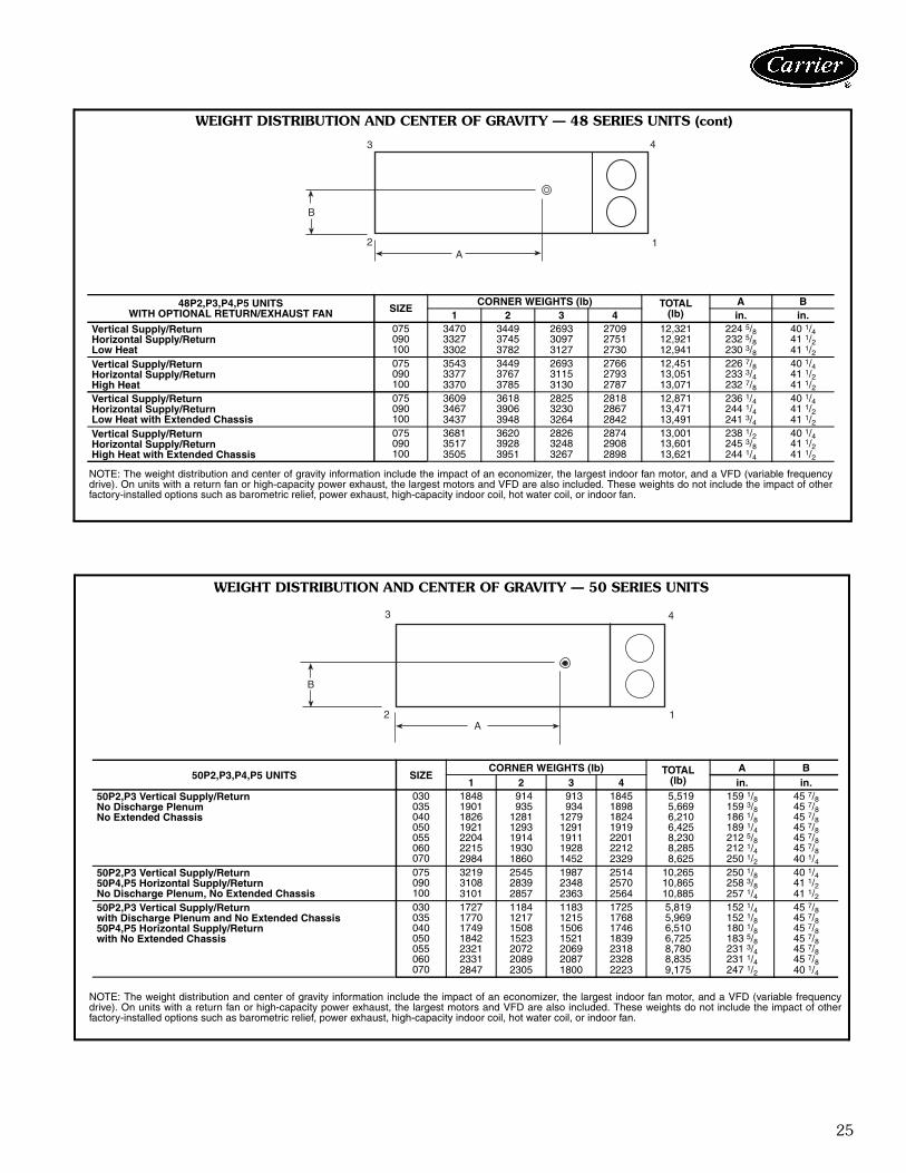
NOTE: The weight distribution and center of gravity information include the impact of an economizer, the largest indoor fan motor, and a VFD (variable frequencydrive). On units with a return fan or high-capacity power exhaust, the largest motors and VFD are also included. These weights do not include the impact of otherfactory-installed options such as barometric relief, power exhaust, high-capacity indoor coil, hot water coil, or indoor fan.
48P2,P3,P4,P5 UNITSWITH OPTIONAL RETURN/EXHAUST FAN SIZE
WEIGHT DISTRIBUTION AND CENTER OF GRAVITY — 48 SERIES UNITS (cont)
WEIGHT DISTRIBUTION AND CENTER OF GRAVITY — 50 SERIES UNITS
B
2
3 4
1A
NOTE: The weight distribution and center of gravity information include the impact of an economizer, the largest indoor fan motor, and a VFD (variable frequencydrive). On units with a return fan or high-capacity power exhaust, the largest motors and VFD are also included. These weights do not include the impact of otherfactory-installed options such as barometric relief, power exhaust, high-capacity indoor coil, hot water coil, or indoor fan.
WEIGHT DISTRIBUTION AND CENTER OF GRAVITY — 50 SERIES UNITS (cont)
B
2
3 4
1A
LEGEND
PE — Power Exhaust
NOTE: The weight distribution and center of gravity information include the impact of an economizer, the largest indoor fan motor, and a VFD (variable frequencydrive). On units with a return fan or high-capacity power exhaust, the largest motors and VFD are also included. These weights do not include the impact of otherfactory-installed options such as barometric relief, power exhaust, high-capacity indoor coil, hot water coil, or indoor fan.
50P2,P3,P4,P5 UNITS SIZECORNER WEIGHTS (lb) TOTAL
(lb)A B
1 2 3 4 in. in.50P2,P3 Vertical Supply/Returnwith Extended Chassis
*Sizes 040,050 only.†Horizontal discharge units (50 Series only).**Vertical discharge and extended plenum units.NOTE: Part numbers are Browning Manufacturing Corp. reference.
LEGEND *Factory installed.†Field installed.**A special order is offered to meet specific customer requirements. Quotations
for special order options can be requested via the Carrier ETO process. Leadtimes and prices vary with the option.
†† Standard 2-in. filter track may be field converted to accept 4-in. filters.
ITEM OPTION* ACCESSORY† SPECIAL ORDER**GAS HEAT (48P units only) Low Gas Heat — Aluminized Heat Exchanger X High Gas Heat — Aluminized Heat Exchanger X Low Gas Heat — Stainless Steel Heat Exchanger X High Gas Heat — Stainless Steel Heat Exchanger X Staged Low Gas Heat — Stainless Steel Heat Exchanger X Staged High Gas Heat — Stainless Steel Heat Exchanger X Modulating Low Gas Heat — Stainless Steel Heat Exchanger X Modulating High Gas Heat — Stainless Steel Heat Exchanger XELECTRIC HEAT (50P units only) Staged Electric Heat X SCR Controlled Electric Heat X XHYDRONIC HEAT (50P units only) 2-Row Hot Water Coil X Modulating Hot Water Control Valve X Steam Coil XINDOOR AIR QUALITY Double Wall Construction in Airstream X AgION® Double Wall Construction in Airstream X Outdoor Air cfm Station X MERV 7 Pleated, 2-in. Filter Package X MERV 11 Pleated, 2-in. Filter Package (sizes 075-100 only) X MERV 14 Bag Filter Package with Integral 2-in. Prefilters (sizes 030-070 only) X 12 in. Cartridge Filter with Integral 2-in. Thick Prefilters (sizes 030-070 only) X MERV 8 2-in. Thick Filter Kit X MERV 8 4-in. Thick Filter Kit †† X MERV 11 4-in. Thick Filter Kit †† X MERV 13 4-in. Thick Filter Kit †† X MERV 14 4-in. Thick Filter Kit †† X MERV 14, 12-in. Cartridge Filter Kit (sizes 030-070 only) X UVC Lamps (with Door Interlocks and Disconnect Switch) XECONOMIZER Manual Outside-Air, Self-Closing Damper X Enthalpy Control Economizer X Ultra Low Leak Economizer X Outdoor or Return Humidity Sensor (Enthalpy) XEXHAUST AIR CONTROL Barometric Relief X Non-Modulating Power Exhaust X Modulating Power Exhaust with VFD X Modulating Power Exhaust with VFD and Bypass X High-Capacity Power Exhaust with VFD (sizes 075-100 only) X Return Fan with VFD (sizes 075-100 only) XCONDENSER AND EVAPORATOR COIL Al/Al E-Coat Novation® MCHX Condenser Coil X High-Capacity Evaporator Coil X Pre-Coat Al/Cu Evaporator Coil X E-Coat Al/Cu Evaporator Coil X Cu/Cu Evaporator Coil X Hot Gas Bypass (Circuit A) X Condenser Coil Hail Guard Assembly (sizes 030-060 only) X Humidi-MiZer® Adaptive Dehumidification System XPOWER CIRCUIT GFI Convenience Outlet (Powered on Load-Side) X GFI Convenience Outlet (Non-Powered) X Power Terminal Block X Non-Fused Disconnect X Disconnect with UL489 Circuit Breaker (HACR) X Fused Disconnect X Phase Protection Monitor X 65KA Short Circuit Current Rating (208,230,460 volt) X 25KA Short Circuit Current Rating (575 volt only) X
Al — AluminumCu — CopperETO — Engineered-To-OrderGFI — Ground Fault InterrruptIFM — Indoor Fan MotorMCHX — Microchannel Heat ExchangerSCR — Silicon Controlled RectifierUVC — UltravioletVFD — Variable Frequency Drive
Options and accessories
30
Chassis arrangements (48 Series units)Standard length chassis with vertical discharge —The standard, compact, vertical discharge arrangement isprovided with a bottom, return-air opening, straight-through air path, and horizontal discharge into the heatingsection with bottom supply air outlet. Ductwork is attachedto accessory roof curb. These units are available withfactory-installed optional power exhaust or barometric reliefpackages in conjunction with factory-installed optionaleconomizers.
Vertical discharge with optional return fan — Thisvertical discharge arrangement adds a factory-installedreturn fan and VFD. Return air enters through the bottomopening upstream of the return fan and follows a straight-through path to the supply fan and into the heating section,where it exits through the bottom supply air outlet. Duct-work is attached to the accessory roof curb.
ITEM OPTION* ACCESSORY† SPECIAL ORDER**CONTROLS Controls Expansion Module (CEM) X X BACnet Communication X System Pilot™ Interface X Touch Pilot™ Interface X Navigator™ Display X Return Air CO2 Sensor X CO2 Space Sensor X Return Air Smoke Detector X Return and Supply Air Smoke Detectors Installed X Filter Switch X Fan Status Switch (requires CEM) X T-55 Space Temperature Sensor with Override X T-56 Space Temperature Sensor with Override and Set Point Adjustment X Space Temperature Sensor with CO2 Override X Space Temperature Sensor with CO2 Override and Set Point Adjustment X MODBUS Carrier Translator X LonWorks Carrier Translator XINDOOR FAN AND MOTOR Bypass on IFM VFD X Airfoil Fan (sizes 075-100 only) XPACKAGING Domestic X Export XMISCELLANEOUS Digital Compressor X Refrigeration Service Valves X Replacable Core Filter Drier X Extended Chassis X 14-in. Roof Curb X Condenser Section Roof Curb (sizes 070-100 only) X Security Grille (sizes 070-100 only) X Low Ambient Control X X Extended Lube Lines X Access Door Retainers X Horizontal Supply / Vertical Return X Vertical Supply / Horizontal Return X Low Outdoor Sound X Low Compressor Sound X
STANDARD CHASSIS
a48-8426
OPTIONAL RETURN FAN
a48-8427
Options and accessories (cont)
31
Extended length chassis with vertical discharge —The extended length chassis arrangement provides an addi-tional 25-in. of unit length located between the evaporatorcoil section and the supply fan sled. This compartment isused for field-installation of an auxiliary coil. The auxiliarycoil can be a hydronic heating coil, a steam heating coil, ora refrigeration heat reclaim coil. The extended length com-partment includes tracks to accept the field-supplied andinstalled auxiliary coil.
Vertical discharge with optional high-capacity mod-ulating power exhaust system — This vertical dis-charge arrangement adds a factory-installed extended rearplenum to house the integrated economizer and high-capacity modulating power exhaust systems (standard fea-tures on these models). Return air enters unit through bot-tom opening upstream of the power exhaust system andfollows a straight-through path to the supply fan and intothe heating section, where it exits unit through bottom sup-ply air outlet. Ductwork is attached to accessory roof curb.
Chassis arrangements — (50 Series units)Standard length chassis with vertical discharge —The standard, compact, vertical discharge arrangement isprovided with a bottom return-air opening, straight-throughair path, and direct, vertical-discharge, supply fan for bot-tom supply air. Ductwork is attached to accessory roofcurb. These units are available with factory-installedoptional electric heat. Factory-installed optional powerexhaust is available in conjunction with factory-installedoptional economizer.
Vertical discharge with optional return fan — Thisvertical discharge arrangement adds a factory-installedreturn fan with VFD and extended rear plenum. Return airenters unit through bottom opening upstream of the returnfan and follows a straight-through path to the supply fanand into the extended plenum section, where it exits unitthrough bottom supply air outlet. Ductwork is attached toaccessory roof curb. Return air exhaust outlet is on the endof the chassis. Factory-installed optional electric heat isavailable on these units.
Standard length chassis with vertical discharge anddischarge plenum — The standard, vertical dischargearrangement is provided with a bottom, return-air open-ing, straight-through air path. The supply fan is arrangedfor horizontal outlet into the discharge plenum area. Sup-ply air exits from the discharge plenum area downwardthrough the bottom of the unit. Ductwork is attached toaccessory roof curb. These units are available with factory-installed optional power exhaust or barometric relief pack-ages in conjunction with factory-installed optional econo-mizers.
Standard length chassis with horizontal discharge— The standard, compact, horizontal discharge arrange-ment is provided with a return-air end opening, straight-through air path, and supply-air discharge on the unit lefthand side. Ductwork is attached to flanges on the outercabinet. Electric heaters are not available on size 030-070units. Factory-installed optional economizers are available.Factory-installed power exhaust is available.
COILCOMPARTMENT
EXTENDED LENGTH CHASSIS
a48-8428
OPTIONAL HIGH-CAPACITY POWER EXHAUST
STANDARD CHASSIS
OPTIONAL RETURN FAN
DISCHARGEPLENUM
STANDARD CHASSIS WITH DISCHARGE PLENUM
STANDARD CHASSIS WITH HORIZONTAL DISCHARGE
32
Vertical discharge with optional high-capacity mod-ulating power exhaust systems — This vertical dis-charge arrangement adds a factory-installed extended rearplenum to house the integrated economizer and high-capacity modulating power exhaust systems (standard fea-tures on these models). Return air enters unit through bot-tom opening upstream of the power exhaust system andfollows a straight-through path to the supply fan and intothe extended plenum section, where it exits unit throughbottom supply air outlet. Ductwork is attached to accessoryroof curb. Economizer inlets are on both sides of the unit;power exhaust outlet is on the end of the chassis. Factory-installed optional electric heat is available on these units.
Horizontal discharge with optional high-capacitymodulating power exhaust systems — This horizontaldischarge arrangement adds a factory-installed extendedrear plenum to house the integrated economizer and high-capacity modulating power exhaust systems (standard fea-tures on these models). Return air enters the chassisthrough dual openings on the left-hand side of unit. Thesupply fan discharges horizontally into the extended ple-num section with unit supply air outlet on the left-handside. Ductwork is attached to flanges on the outer cabinet.Economizer inlets are on both sides of the unit; powerexhaust outlet is on the end of the chassis.
Horizontal discharge with optional return fan andmodulating exhaust damper — This horizontal dis-charge arrangement adds a factory-installed return fan withVFD and extended rear plenum. Return air enters thechassis through the bottom opening upstream of the returnfan. The supply fan discharges horizontally into theextended plenum section with unit supply air outlet on theleft-hand side. Ductwork is attached to flanges on the outercabinet. Return air exhaust outlet is on the end of thechassis.
Extended length chassis with vertical discharge —The extended length, vertical discharge arrangement isprovided with a bottom, return-air opening, straight-through air path, and direct, vertical-discharge, supply fanfor bottom supply air. Ductwork is attached to accessoryroof curb. These units are available with factory-installedoptional power exhaust or barometric relief packages inconjunction with factory-installed optional economizers.
Extended length chassis with vertical dischargeand discharge plenum — The extended length verticaldischarge arrangement is provided with a bottom, return-air opening, straight-through air path. The supply fan isarranged for horizontal outlet into the extended plenumarea. Supply air exits from the extended plenum areadownward through the bottom of the unit. Ductwork isattached to accessory roof curb. These units are availablewith factory-installed optional power exhaust or barometricrelief packages in conjunction with factory-installedoptional economizers. Electric heaters are not available onthese units.
Extended length chassis with horizontal discharge— The extended length horizontal discharge arrangementis provided with a return-air end opening, straight-throughair path, and supply-air discharge on the unit left handside. Ductwork is attached to flanges on the outer cabinet.Electric heaters and barometric relief packages are notavailable on these units. Factory-installed optional econo-mizers are available. Factory-installed optional powerexhaust is available.
OPTIONAL HIGH-CAPACITY POWER EXHAUST
OPTIONAL HIGH-CAPACITY POWER EXHAUST
OPTIONAL RETURN FAN
COILCOMPARTMENT
EXTENDED LENGTH CHASSIS
COILCOMPARTMENT
DISCHARGEPLENUM
EXTENDED LENGTH CHASSIS WITH DISCHARGE PLENUM
COILCOMPARTMENT
EXTENDED LENGTH CHASSIS
Options and accessories (cont)
33
48P4,P
5030,0
35 U
NIT
Thi
s se
ctio
n de
tails
six
exa
mpl
es o
f th
e P
Ser
ies
larg
e ro
ofto
p un
it. T
o de
term
ine
dim
ensi
ons
for
the
appr
opria
te
unit
for
your
ap
plic
atio
n,
refe
r to
th
eA
pplie
d R
oofto
p B
uild
er s
oftw
are.
a48-8444
Base unit dimension examples
34
50P2,P
3030
,035 U
NIT
S (U
NIT
WIT
H O
PTIO
NA
L EX
TEN
DED
PLE
NU
M S
HO
WN
)
Thi
s se
ctio
n de
tails
six
exa
mpl
es o
f th
e P
Ser
ies
larg
e ro
ofto
p un
it. T
o de
term
ine
dim
ensi
ons
for
the
appr
opria
te
unit
for
your
ap
plic
atio
n,
refe
r to
th
eA
pplie
d R
oofto
p B
uild
er s
oftw
are.
a50-8376
Base unit dimension examples (cont)
35
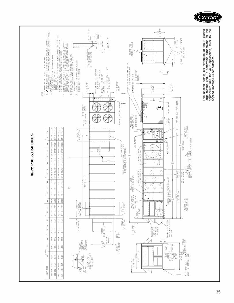
48P2,P
3055,0
60 U
NIT
S
Thi
s se
ctio
n de
tails
six
exa
mpl
es o
f th
e P
Ser
ies
larg
e ro
ofto
p un
it. T
o de
term
ine
dim
ensi
ons
for
the
appr
opria
te
unit
for
your
ap
plic
atio
n,
refe
r to
th
eA
pplie
d R
oofto
p B
uild
er s
oftw
are.
a48-8635
36
50P2,P
3055,0
60 U
NIT
S
Thi
s se
ctio
n de
tails
six
exa
mpl
es o
f th
e P
Ser
ies
larg
e ro
ofto
p un
it. T
o de
term
ine
dim
ensi
ons
for
the
appr
opria
te
unit
for
your
ap
plic
atio
n,
refe
r to
th
eA
pplie
d R
oofto
p B
uild
er s
oftw
are.
a50-8714
Base unit dimension examples (cont)
37
48P4,P
5075-1
00 U
NIT
S
Thi
s se
ctio
n de
tails
six
exa
mpl
es o
f th
e P
Ser
ies
larg
e ro
ofto
p un
it. T
o de
term
ine
dim
ensi
ons
for
the
appr
opria
te
unit
for
your
ap
plic
atio
n,
refe
r to
th
eA
pplie
d R
oofto
p B
uild
er s
oftw
are.
a48-8636
38
50P2,P
3075-1
00 U
NIT
S (U
NIT
S W
ITH
OPTIO
NA
L H
IGH
-CA
PAC
ITY
PO
WER
EX
HA
UST S
HO
WN
)
Thi
s se
ctio
n de
tails
six
exa
mpl
es o
f th
e P
Ser
ies
larg
e ro
ofto
p un
it. T
o de
term
ine
dim
ensi
ons
for
the
appr
opria
te
unit
for
your
ap
plic
atio
n,
refe
r to
th
eA
pplie
d R
oofto
p B
uild
er s
oftw
are.
a48-8432
Base unit dimension examples (cont)
39
RO
OF
CU
RB
— S
IZES 0
30-0
50
a48-8433
Accessory dimensions
40
RO
OF
CU
RB
— S
IZES 0
55,0
60
a48-8434
Accessory dimensions (cont)
41
RO
OF
CU
RB
— S
IZES 0
70-1
00
a48-8435
42
CO
ND
EN
SER
SEC
TIO
N R
OO
F C
UR
B —
SIZ
ES 0
70 A
ND
07
5a48-8436
Accessory dimensions (cont)
43
CO
ND
EN
SER
SEC
TIO
N R
OO
F C
UR
B —
SIZ
ES 0
90 A
ND
10
0
a48-8437
44
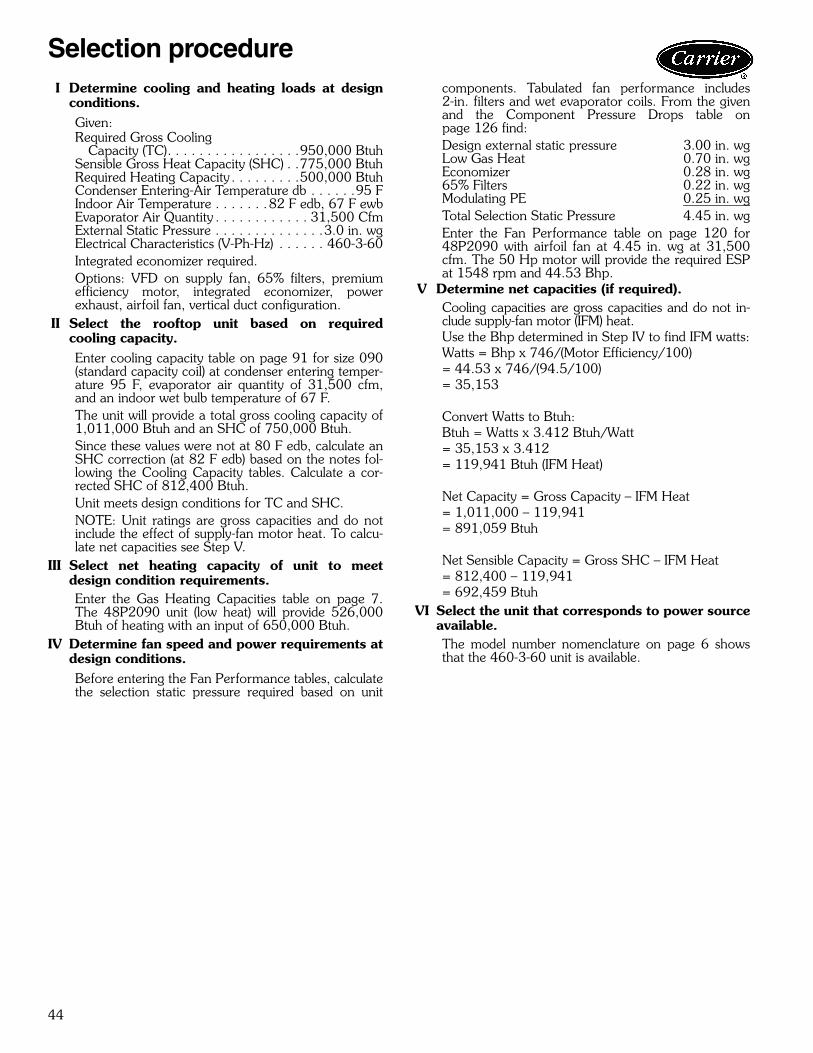
I Determine cooling and heating loads at designconditions.Given:Required Gross Cooling
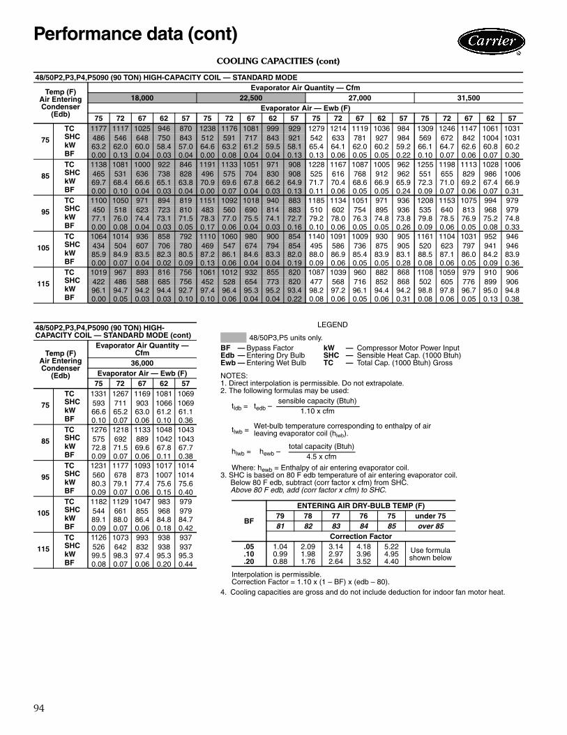
II Select the rooftop unit based on requiredcooling capacity.Enter cooling capacity table on page 91 for size 090(standard capacity coil) at condenser entering temper-ature 95 F, evaporator air quantity of 31,500 cfm,and an indoor wet bulb temperature of 67 F.The unit will provide a total gross cooling capacity of1,011,000 Btuh and an SHC of 750,000 Btuh.Since these values were not at 80 F edb, calculate anSHC correction (at 82 F edb) based on the notes fol-lowing the Cooling Capacity tables. Calculate a cor-rected SHC of 812,400 Btuh.Unit meets design conditions for TC and SHC.NOTE: Unit ratings are gross capacities and do notinclude the effect of supply-fan motor heat. To calcu-late net capacities see Step V.
III Select net heating capacity of unit to meetdesign condition requirements.Enter the Gas Heating Capacities table on page 7.The 48P2090 unit (low heat) will provide 526,000Btuh of heating with an input of 650,000 Btuh.
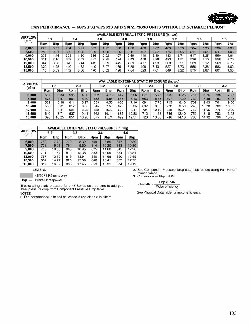
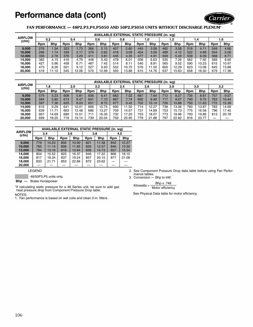
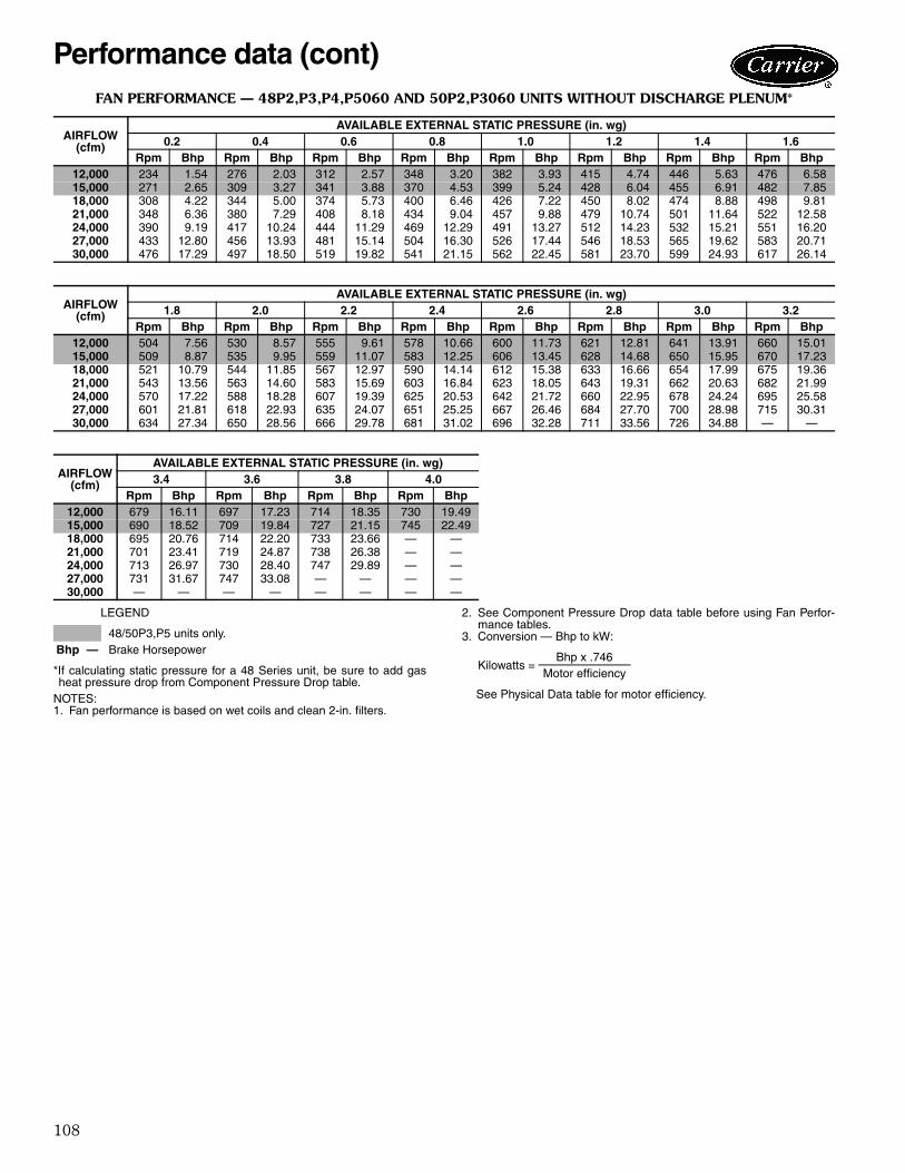
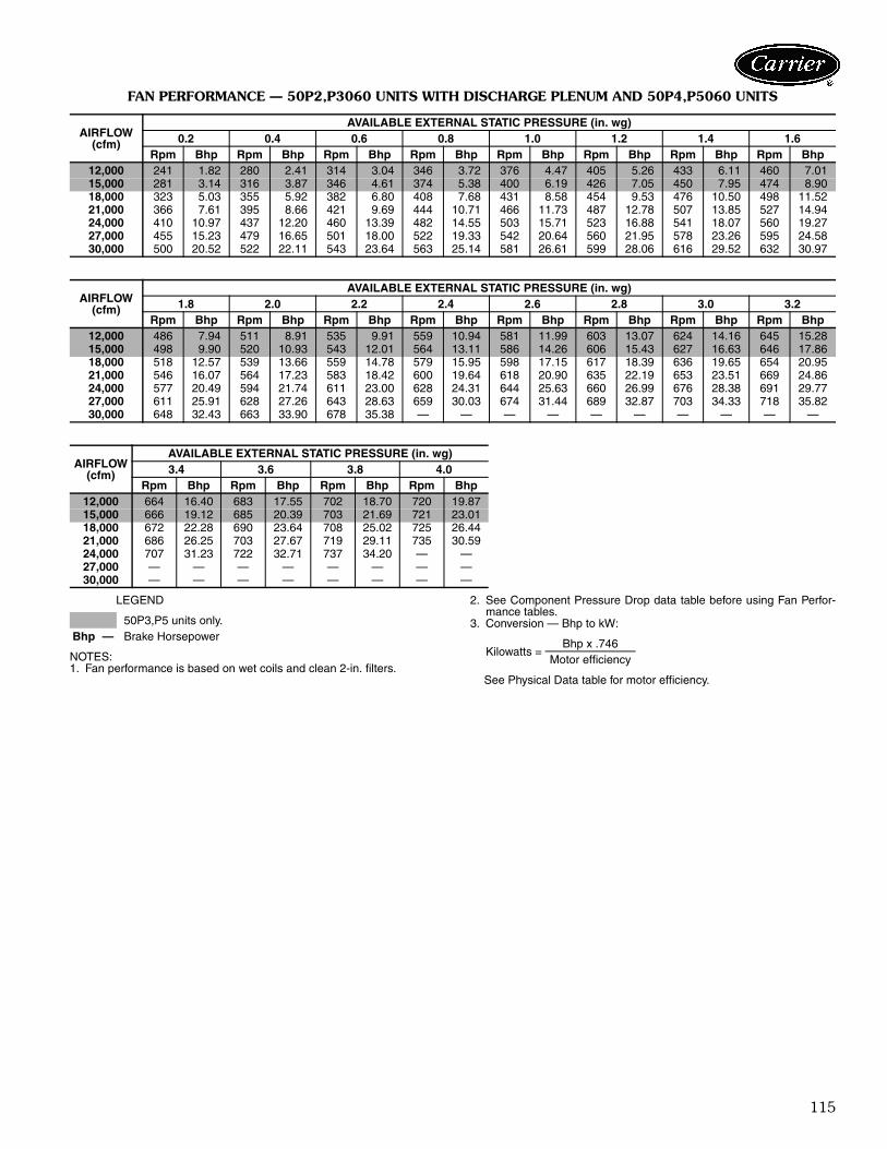
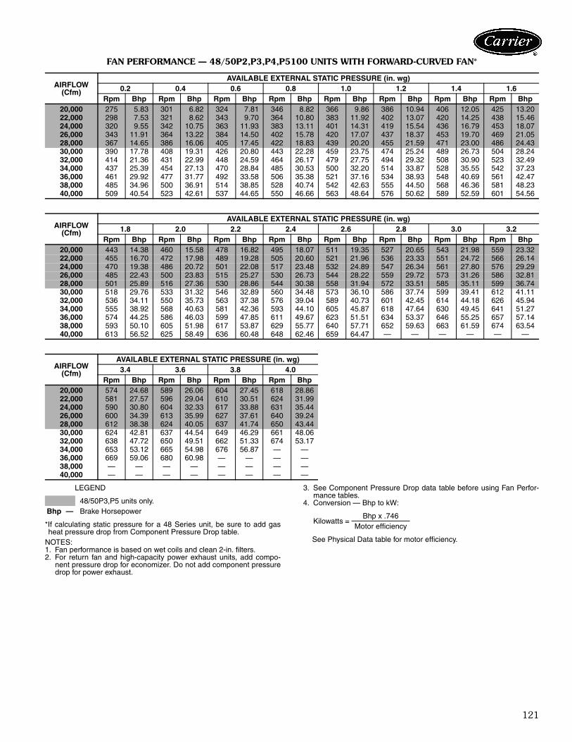
IV Determine fan speed and power requirements atdesign conditions.Before entering the Fan Performance tables, calculatethe selection static pressure required based on unit
components. Tabulated fan performance includes2-in. filters and wet evaporator coils. From the givenand the Component Pressure Drops table onpage 126 find:Design external static pressure 3.00 in. wgLow Gas Heat 0.70 in. wgEconomizer 0.28 in. wg65% Filters 0.22 in. wgModulating PE 0.25 in. wgTotal Selection Static Pressure 4.45 in. wgEnter the Fan Performance table on page 120 for48P2090 with airfoil fan at 4.45 in. wg at 31,500cfm. The 50 Hp motor will provide the required ESPat 1548 rpm and 44.53 Bhp.
V Determine net capacities (if required).Cooling capacities are gross capacities and do not in-clude supply-fan motor (IFM) heat.Use the Bhp determined in Step IV to find IFM watts:Watts = Bhp x 746/(Motor Efficiency/100)= 44.53 x 746/(94.5/100)= 35,153
Convert Watts to Btuh:Btuh = Watts x 3.412 Btuh/Watt= 35,153 x 3.412= 119,941 Btuh (IFM Heat)
VI Select the unit that corresponds to power sourceavailable.The model number nomenclature on page 6 showsthat the 460-3-60 unit is available.
Selection procedure
45
Humidi-MiZer® performance dataThe following pages of Performance Data include perfor-mance tables for Humidi-MiZer equipped units. The tablesinclude capacity in normal cooling, subcooling mode andhot gas reheat mode. For hot gas reheat performance, the ambient outdoor airand return air temperature ranges are different from theranges listed for normal design cooling and subcoolingrooftop operation. This is to provide appropriate perfor-mance data for those conditions when the rooftop unitwould most likely respond to provide all latent capacity re-moval from the space. All performance data are provided in terms of gross ca-pacities. Combined, the subcooling and reheat tables pro-vide the endpoints of performance potential for each unit
at specific conditions. In reality, the P Series Humidi-MiZerequipped unit will modulate refrigerant bypass flow to en-sure that it meets the supply air set point while maintaininglow evaporator temperatures needed for maximum mois-ture removal. This means that the unit sensible capacityvaries between the two tables, depending on the load inthe space. The chart below graphically demonstrates this capability.Note that latent capacity stays fairly constant between Sub-cooling mode and Hot Gas Reheat mode, while sensiblecapacity varies almost infinitely between the two endpointsof the table. This clearly demonstrates how accurate spacetemperature and humidity control can be maintainedthrough the P Series innovative modulating refrigerant flowHumidi-MiZer application.
30.0
40.0
50.0
60.0
apac
ity (T
ons)
Variable Sensible Heat Ratio (SHR) Example 80 F dB/67 F wB Ent Air, 95 F Outdoor, Constant Volume CFM
Sensible
Latent
In this example, unit SHR can range from 0.00 to 0.60 between Reheat and Subcooling modes depending on space requirements. Refrigerant flow to the Humidi-MiZer coil will be modulated to meet the SHR required. In normal cooling mode, the unit would operate at 0.66 SHR.
0.66 SHR
0.60 SHR
0.0
10.0
20.0
lamroNloocbuS %001taeheR %001
Ca
0.00 SHR
Performance data
46
COOLING CAPACITIES
LEGEND
NOTES:1. Direct interpolation is permissible. Do not extrapolate.2. The following formulas may be used:
Where: hewb = Enthalpy of air entering evaporator coil.
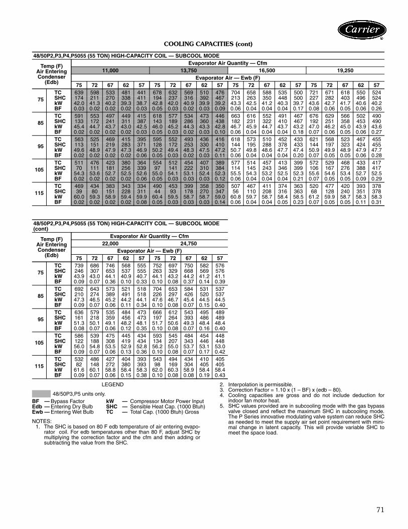
3. SHC is based on 80 F edb temperature of air entering evaporatorcoil.Below 80 F edb, subtract (corr factor x cfm) from SHC.Above 80 F edb, add (corr factor x cfm) to SHC.
Interpolation is permissible.Correction Factor = 1.10 x (1 – BF) x (edb – 80).
4. Cooling capacities are gross and do not include deduction for indoorfan motor heat.
48/50P2,P3,P4,P5030 (30 TON) STANDARD CAPACITY COIL — STANDARD MODE
Temp (F)Air EnteringCondenser
(Edb)
Evaporator Air Quantity — Cfm6,000 7,500 9,000 10,500
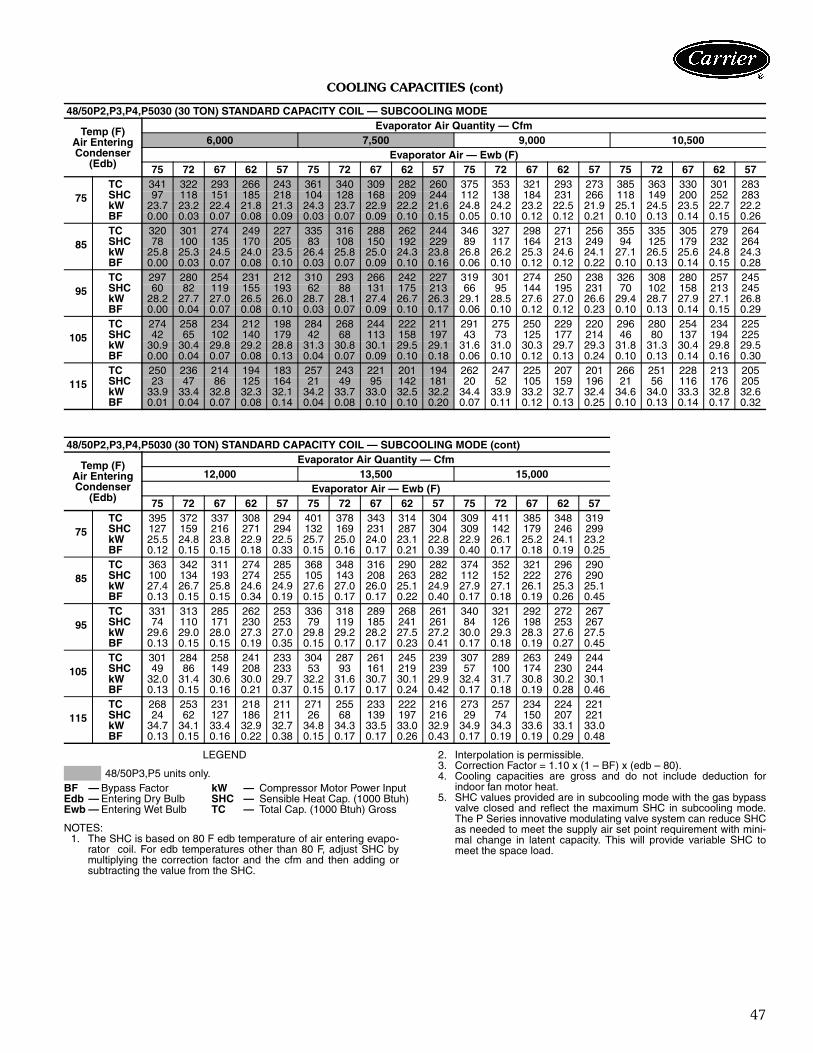
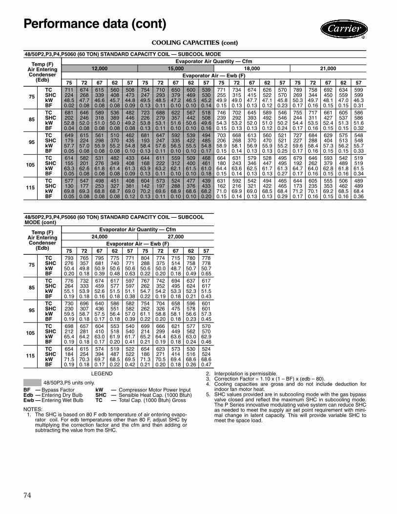
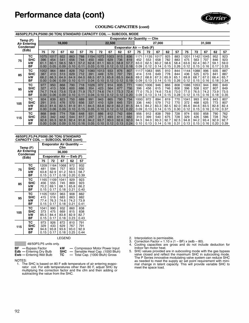
NOTES:1. The SHC is based on 80 F edb temperature of air entering evapo-
rator coil. For edb temperatures other than 80 F, adjust SHC bymultiplying the correction factor and the cfm and then adding orsubtracting the value from the SHC.
2. Interpolation is permissible.3. Correction Factor = 1.10 x (1 – BF) x (edb – 80).4. Cooling capacities are gross and do not include deduction for
indoor fan motor heat.5. SHC values provided are in subcooling mode with the gas bypass
valve closed and reflect the maximum SHC in subcooling mode.The P Series innovative modulating valve system can reduce SHCas needed to meet the supply air set point requirement with mini-mal change in latent capacity. This will provide variable SHC tomeet the space load.
48/50P2,P3,P4,P5030 (30 TON) STANDARD CAPACITY COIL — SUBCOOLING MODE
Temp (F)Air EnteringCondenser
(Edb)
Evaporator Air Quantity — Cfm6,000 7,500 9,000 10,500
48/50P3,P5 units only.BF — Bypass Factor kW — Compressor Motor Power InputEdb — Entering Dry Bulb SHC — Sensible Heat Cap. (1000 Btuh)Ewb — Entering Wet Bulb TC — Total Cap. (1000 Btuh) Gross
48
COOLING CAPACITIES (cont)
LEGEND
NOTES:1. The SHC is based on 75 F edb temperature of air entering evapo-
rator coil. For edb temperatures other than 75 F, adjust SHC bymultiplying the correction factor and the cfm and then adding orsubtracting the value from the SHC.
2. Interpolation is permissible.3. Correction Factor = 1.10 x (1 – BF) x (edb – 75).4. Cooling capacities are gross and do not include deduction for
indoor fan motor heat.5. Capacity table includes impact of outdoor fan staging at tempera-
tures below 75 F.
6. SHC values provided reflect maximum reheat values with 100%gas bypass. Negative SHC value indicates that the air enteringthe coil is being heated at 100% gas bypass. The P Series innova-tive modulating valve system will reduce the gas bypass asrequired to meet the supply air setpoint with minimal change inlatent capacity. The space will NOT be overheated and the unitwill provide variable SHC to meet the space load.
48/50P2,P3,P4,P5030 (30 TON) STANDARD CAPACITY COIL — HOT GAS REHEAT MODE
NOTES:1. Direct interpolation is permissible. Do not extrapolate.2. The following formulas may be used:
Where: hewb = Enthalpy of air entering evaporator coil.
3. SHC is based on 80 F edb temperature of air entering evaporatorcoil.Below 80 F edb, subtract (corr factor x cfm) from SHC.Above 80 F edb, add (corr factor x cfm) to SHC.
Interpolation is permissible.Correction Factor = 1.10 x (1 – BF) x (edb – 80).
4. Cooling capacities are gross and do not include deduction for indoorfan motor heat.
48/50P2,P3,P4,P5030 (30 TON) HIGH-CAPACITY COIL — STANDARD MODE
Temp (F)Air EnteringCondenser
(Edb)
Evaporator Air Quantity — Cfm6,000 7,500 9,000 10,500
NOTES:1. The SHC is based on 80 F edb temperature of air entering evapo-
rator coil. For edb temperatures other than 80 F, adjust SHC bymultiplying the correction factor and the cfm and then adding orsubtracting the value from the SHC.
2. Interpolation is permissible.3. Correction Factor = 1.10 x (1 – BF) x (edb – 80).4. Cooling capacities are gross and do not include deduction for
indoor fan motor heat.5. SHC values provided are in subcooling mode with the gas bypass
valve closed and reflect the maximum SHC in subcooling mode.The P Series innovative modulating valve system can reduce SHCas needed to meet the supply air set point requirement with mini-mal change in latent capacity. This will provide variable SHC tomeet the space load.
48/50P3,P5 units only.BF — Bypass Factor kW — Compressor Motor Power InputEdb — Entering Dry Bulb SHC — Sensible Heat Cap. (1000 Btuh)Ewb — Entering Wet Bulb TC — Total Cap. (1000 Btuh) Gross
Performance data (cont)
51
COOLING CAPACITIES (cont)
LEGEND
NOTES:1. The SHC is based on 75 F edb temperature of air entering evapo-
rator coil. For edb temperatures other than 75 F, adjust SHC bymultiplying the correction factor and the cfm and then adding orsubtracting the value from the SHC.
2. Interpolation is permissible.3. Correction Factor = 1.10 x (1 – BF) x (edb – 75).4. Cooling capacities are gross and do not include deduction for
indoor fan motor heat.5. Capacity table includes impact of outdoor fan staging at tempera-
tures below 75 F.
6. SHC values provided reflect maximum reheat values with 100%gas bypass. Negative SHC value indicates that the air enteringthe coil is being heated at 100% gas bypass. The P Series innova-tive modulating valve system will reduce the gas bypass asrequired to meet the supply air setpoint with minimal change inlatent capacity. The space will NOT be overheated and the unitwill provide variable SHC to meet the space load.
48/50P2,P3,P4,P5030 (30 TON) HIGH-CAPACITY COIL — HOT GAS REHEAT MODE
NOTES:1. The SHC is based on 80 F edb temperature of air entering evapo-
rator coil. For edb temperatures other than 80 F, adjust SHC bymultiplying the correction factor and the cfm and then adding orsubtracting the value from the SHC.
2. Interpolation is permissible.3. Correction Factor = 1.10 x (1 – BF) x (edb – 80).4. Cooling capacities are gross and do not include deduction for
indoor fan motor heat.5. SHC values provided are in subcooling mode with the gas bypass
valve closed and reflect the maximum SHC in subcooling mode.The P Series innovative modulating valve system can reduce SHCas needed to meet the supply air set point requirement with mini-mal change in latent capacity. This will provide variable SHC tomeet the space load.
48/50P2,P3,P4,P5035 (35 TON) STANDARD CAPACITY COIL — SUBCOOL MODE
Temp (F)Air EnteringCondenser
(Edb)
Evaporator Air Quantity — Cfm7,000 8,750 9,625 10,500
48/50P3,P5 units only.BF — Bypass Factor kW — Compressor Motor Power InputEdb — Entering Dry Bulb SHC — Sensible Heat Cap. (1000 Btuh)Ewb — Entering Wet Bulb TC — Total Cap. (1000 Btuh) Gross
54
COOLING CAPACITIES (cont)
LEGEND
NOTES:1. The SHC is based on 75 F edb temperature of air entering evapo-
rator coil. For edb temperatures other than 75 F, adjust SHC bymultiplying the correction factor and the cfm and then adding orsubtracting the value from the SHC.
2. Interpolation is permissible.3. Correction Factor = 1.10 x (1 – BF) x (edb – 75).4. Cooling capacities are gross and do not include deduction for
indoor fan motor heat.5. Capacity table includes impact of outdoor fan staging at tempera-
tures below 75 F.
6. SHC values provided reflect maximum reheat values with 100%gas bypass. Negative SHC value indicates that the air enteringthe coil is being heated at 100% gas bypass. The P Series innova-tive modulating valve system will reduce the gas bypass asrequired to meet the supply air setpoint with minimal change inlatent capacity. The space will NOT be overheated and the unitwill provide variable SHC to meet the space load.
48/50P2,P3,P4,P5035 (35 TON) STANDARD CAPACITY COIL — HOT GAS REHEAT MODE
NOTES:1. The SHC is based on 80 F edb temperature of air entering evapo-
rator coil. For edb temperatures other than 80 F, adjust SHC bymultiplying the correction factor and the cfm and then adding orsubtracting the value from the SHC.
2. Interpolation is permissible.3. Correction Factor = 1.10 x (1 – BF) x (edb – 80).4. Cooling capacities are gross and do not include deduction for
indoor fan motor heat.5. SHC values provided are in subcooling mode with the gas bypass
valve closed and reflect the maximum SHC in subcooling mode.The P Series innovative modulating valve system can reduce SHCas needed to meet the supply air set point requirement with mini-mal change in latent capacity. This will provide variable SHC tomeet the space load.
48/50P2,P3,P4,P5040 (40 TON) STANDARD CAPACITY COIL — SUBCOOL MODE
Temp (F)Air EnteringCondenser
(Edb)
Evaporator Air Quantity — Cfm8,000 10,000 12,000 14,000
48/50P3,P5 units only.BF — Bypass Factor kW — Compressor Motor Power InputEdb — Entering Dry Bulb SHC — Sensible Heat Cap. (1000 Btuh)Ewb — Entering Wet Bulb TC — Total Cap. (1000 Btuh) Gross
Performance data (cont)
57
COOLING CAPACITIES (cont)
LEGEND
NOTES:1. The SHC is based on 75 F edb temperature of air entering evapo-
rator coil. For edb temperatures other than 75 F, adjust SHC bymultiplying the correction factor and the cfm and then adding orsubtracting the value from the SHC.
2. Interpolation is permissible.
3. Correction Factor = 1.10 x (1 – BF) x (edb – 75).4. Cooling capacities are gross and do not include deduction for
indoor fan motor heat.5. Capacity table includes impact of outdoor fan staging at tempera-
tures below 75 F.6. SHC values provided reflect maximum reheat values with 100%
gas bypass. Negative SHC value indicates that the air enteringthe coil is being heated at 100% gas bypass. The P Series innova-tive modulating valve system will reduce the gas bypass asrequired to meet the supply air setpoint with minimal change inlatent capacity. The space will NOT be overheated and the unitwill provide variable SHC to meet the space load.
48/50P2,P3,P4,P5040 (40 TON) STANDARD CAPACITY COIL — HOT GAS REHEAT MODE
NOTES:1. The SHC is based on 80 F edb temperature of air entering evapo-
rator coil. For edb temperatures other than 80 F, adjust SHC bymultiplying the correction factor and the cfm and then adding orsubtracting the value from the SHC.
2. Interpolation is permissible.3. Correction Factor = 1.10 x (1 – BF) x (edb – 80).4. Cooling capacities are gross and do not include deduction for
indoor fan motor heat.5. SHC values provided are in subcooling mode with the gas bypass
valve closed and reflect the maximum SHC in subcooling mode.The P Series innovative modulating valve system can reduce SHCas needed to meet the supply air set point requirement with mini-mal change in latent capacity. This will provide variable SHC tomeet the space load.
48/50P3,P5 units only.BF — Bypass Factor kW — Compressor Motor Power InputEdb — Entering Dry Bulb SHC — Sensible Heat Cap. (1000 Btuh)Ewb — Entering Wet Bulb TC — Total Cap. (1000 Btuh) Gross
60
COOLING CAPACITIES (cont)
LEGEND
NOTES:1. The SHC is based on 75 F edb temperature of air entering evapo-
rator coil. For edb temperatures other than 75 F, adjust SHC bymultiplying the correction factor and the cfm and then adding orsubtracting the value from the SHC.
2. Interpolation is permissible.3. Correction Factor = 1.10 x (1 – BF) x (edb – 75).4. Cooling capacities are gross and do not include deduction for
indoor fan motor heat.5. Capacity table includes impact of outdoor fan staging at tempera-
tures below 75 F.
6. SHC values provided reflect maximum reheat values with 100%gas bypass. Negative SHC value indicates that the air enteringthe coil is being heated at 100% gas bypass. The P Series innova-tive modulating valve system will reduce the gas bypass asrequired to meet the supply air setpoint with minimal change inlatent capacity. The space will NOT be overheated and the unitwill provide variable SHC to meet the space load.
48/50P2,P3,P4,P5040 (40 TON) HIGH-CAPACITY COIL — HOT GAS REHEAT MODE
NOTES:1. The SHC is based on 80 F edb temperature of air entering evapo-
rator coil. For edb temperatures other than 80 F, adjust SHC bymultiplying the correction factor and the cfm and then adding orsubtracting the value from the SHC.
2. Interpolation is permissible.3. Correction Factor = 1.10 x (1 – BF) x (edb – 80).4. Cooling capacities are gross and do not include deduction for
indoor fan motor heat.5. SHC values provided are in subcooling mode with the gas bypass
valve closed and reflect the maximum SHC in subcooling mode.The P Series innovative modulating valve system can reduce SHCas needed to meet the supply air set point requirement with mini-mal change in latent capacity. This will provide variable SHC tomeet the space load.
48/50P2,P3,P4,P5050 (50 TON) STANDARD CAPACITY COIL — SUBCOOL MODE
Temp (F)Air EnteringCondenser
(Edb)
Evaporator Air Quantity — Cfm10,000 12,500 15,000 17,500
48/50P3,P5 units only.BF — Bypass Factor kW — Compressor Motor Power InputEdb — Entering Dry Bulb SHC — Sensible Heat Cap. (1000 Btuh)Ewb — Entering Wet Bulb TC — Total Cap. (1000 Btuh) Gross
Performance data (cont)
63
COOLING CAPACITIES (cont)
LEGEND
NOTES:1. The SHC is based on 75 F edb temperature of air entering evapo-
rator coil. For edb temperatures other than 75 F, adjust SHC bymultiplying the correction factor and the cfm and then adding orsubtracting the value from the SHC.
2. Interpolation is permissible.3. Correction Factor = 1.10 x (1 – BF) x (edb – 75).4. Cooling capacities are gross and do not include deduction for
indoor fan motor heat.
5. Capacity table includes impact of outdoor fan staging at tempera-tures below 75 F.
6. SHC values provided reflect maximum reheat values with 100%gas bypass. Negative SHC value indicates that the air enteringthe coil is being heated at 100% gas bypass. The P Series innova-tive modulating valve system will reduce the gas bypass asrequired to meet the supply air setpoint with minimal change inlatent capacity. The space will NOT be overheated and the unitwill provide variable SHC to meet the space load.
48/50P2,P3,P4,P5050 (50 TON) STANDARD CAPACITY COIL — HOT GAS REHEAT MODE
NOTES:1. The SHC is based on 80 F edb temperature of air entering evapo-
rator coil. For edb temperatures other than 80 F, adjust SHC bymultiplying the correction factor and the cfm and then adding orsubtracting the value from the SHC.
2. Interpolation is permissible.3. Correction Factor = 1.10 x (1 – BF) x (edb – 80).4. Cooling capacities are gross and do not include deduction for
indoor fan motor heat.5. SHC values provided are in subcooling mode with the gas bypass
valve closed and reflect the maximum SHC in subcooling mode.The P Series innovative modulating valve system can reduce SHCas needed to meet the supply air set point requirement with mini-mal change in latent capacity. This will provide variable SHC tomeet the space load.
48/50P3,P5 units only.BF — Bypass Factor kW — Compressor Motor Power InputEdb — Entering Dry Bulb SHC — Sensible Heat Cap. (1000 Btuh)Ewb — Entering Wet Bulb TC — Total Cap. (1000 Btuh) Gross
66
COOLING CAPACITIES (cont)
LEGEND
NOTES:1. The SHC is based on 75 F edb temperature of air entering evapo-
rator coil. For edb temperatures other than 75 F, adjust SHC bymultiplying the correction factor and the cfm and then adding orsubtracting the value from the SHC.
2. Interpolation is permissible.3. Correction Factor = 1.10 x (1 – BF) x (edb – 75).4. Cooling capacities are gross and do not include deduction for
indoor fan motor heat.5. Capacity table includes impact of outdoor fan staging at tempera-
tures below 75 F.
6. SHC values provided reflect maximum reheat values with 100%gas bypass. Negative SHC value indicates that the air enteringthe coil is being heated at 100% gas bypass. The P Series innova-tive modulating valve system will reduce the gas bypass asrequired to meet the supply air setpoint with minimal change inlatent capacity. The space will NOT be overheated and the unitwill provide variable SHC to meet the space load.
48/50P2,P3,P4,P5050 (50 TON) HIGH-CAPACITY COIL — HOT GAS REHEAT MODE
NOTES:1. Direct interpolation is permissible. Do not extrapolate.2. The following formulas may be used:
Where: hewb = Enthalpy of air entering evaporator coil.
3. SHC is based on 80 F edb temperature of air entering evaporatorcoil.Below 80 F edb, subtract (corr factor x cfm) from SHC.Above 80 F edb, add (corr factor x cfm) to SHC.
Interpolation is permissible.Correction Factor = 1.10 x (1 – BF) x (edb – 80).
4. Cooling capacities are gross and do not include deduction for indoorfan motor heat.
48/50P2,P3,P4,P5055 (55 TON) STANDARD CAPACITY COIL — STANDARD MODE
Temp (F)Air EnteringCondenser
(Edb)
Evaporator Air Quantity — Cfm11,000 13,750 16,500 19,250
NOTES:1. The SHC is based on 80 F edb temperature of air entering evapo-
rator coil. For edb temperatures other than 80 F, adjust SHC bymultiplying the correction factor and the cfm and then adding orsubtracting the value from the SHC.
2. Interpolation is permissible.3. Correction Factor = 1.10 x (1 – BF) x (edb – 80).4. Cooling capacities are gross and do not include deduction for
indoor fan motor heat.5. SHC values provided are in subcooling mode with the gas bypass
valve closed and reflect the maximum SHC in subcooling mode.The P Series innovative modulating valve system can reduce SHCas needed to meet the supply air set point requirement with mini-mal change in latent capacity. This will provide variable SHC tomeet the space load.
48/50P2,P3,P4,P5055 (55 TON) STANDARD CAPACITY COIL — SUBCOOL MODE
Temp (F)Air EnteringCondenser
(Edb)
Evaporator Air Quantity — Cfm11,000 13,750 16,500 19,250
48/50P3,P5 units only.BF — Bypass Factor kW — Compressor Motor Power InputEdb — Entering Dry Bulb SHC — Sensible Heat Cap. (1000 Btuh)Ewb — Entering Wet Bulb TC — Total Cap. (1000 Btuh) Gross
Performance data (cont)
69
COOLING CAPACITIES (cont)
LEGEND
NOTES:1. The SHC is based on 75 F edb temperature of air entering evapo-
rator coil. For edb temperatures other than 75 F, adjust SHC bymultiplying the correction factor and the cfm and then adding orsubtracting the value from the SHC.
2. Interpolation is permissible.3. Correction Factor = 1.10 x (1 – BF) x (edb – 75).4. Cooling capacities are gross and do not include deduction for
indoor fan motor heat.5. Capacity table includes impact of outdoor fan staging at tempera-
tures below 75 F.
6. SHC values provided reflect maximum reheat values with 100%gas bypass. Negative SHC value indicates that the air enteringthe coil is being heated at 100% gas bypass. The P Series innova-tive modulating valve system will reduce the gas bypass asrequired to meet the supply air setpoint with minimal change inlatent capacity. The space will NOT be overheated and the unitwill provide variable SHC to meet the space load.
48/50P2,P3,P4,P5055 (55 TON) STANDARD CAPACITY COIL — HOT GAS REHEAT MODE
NOTES:1. Direct interpolation is permissible. Do not extrapolate.2. The following formulas may be used:
Where: hewb = Enthalpy of air entering evaporator coil.
3. SHC is based on 80 F edb temperature of air entering evaporatorcoil.Below 80 F edb, subtract (corr factor x cfm) from SHC.Above 80 F edb, add (corr factor x cfm) to SHC.
Interpolation is permissible.Correction Factor = 1.10 x (1 – BF) x (edb – 80).
4. Cooling capacities are gross and do not include deduction for indoorfan motor heat.
48/50P2,P3,P4,P5055 (55 TON) HIGH-CAPACITY COIL — STANDARD MODE
Temp (F)Air EnteringCondenser
(Edb)
Evaporator Air Quantity — Cfm11,000 13,750 16,500 19,250
NOTES:1. The SHC is based on 80 F edb temperature of air entering evapo-
rator coil. For edb temperatures other than 80 F, adjust SHC bymultiplying the correction factor and the cfm and then adding orsubtracting the value from the SHC.
2. Interpolation is permissible.3. Correction Factor = 1.10 x (1 – BF) x (edb – 80).4. Cooling capacities are gross and do not include deduction for
indoor fan motor heat.5. SHC values provided are in subcooling mode with the gas bypass
valve closed and reflect the maximum SHC in subcooling mode.The P Series innovative modulating valve system can reduce SHCas needed to meet the supply air set point requirement with mini-mal change in latent capacity. This will provide variable SHC tomeet the space load.
48/50P3,P5 units only.BF — Bypass Factor kW — Compressor Motor Power InputEdb — Entering Dry Bulb SHC — Sensible Heat Cap. (1000 Btuh)Ewb — Entering Wet Bulb TC — Total Cap. (1000 Btuh) Gross
72
COOLING CAPACITIES (cont)
LEGEND
NOTES:1. The SHC is based on 75 F edb temperature of air entering evapo-
rator coil. For edb temperatures other than 75 F, adjust SHC bymultiplying the correction factor and the cfm and then adding orsubtracting the value from the SHC.
2. Interpolation is permissible.
3. Correction Factor = 1.10 x (1 – BF) x (edb – 75).4. Cooling capacities are gross and do not include deduction for
indoor fan motor heat.5. Capacity table includes impact of outdoor fan staging at tempera-
tures below 75 F.6. SHC values provided reflect maximum reheat values with 100%
gas bypass. Negative SHC value indicates that the air enteringthe coil is being heated at 100% gas bypass. The P Series innova-tive modulating valve system will reduce the gas bypass asrequired to meet the supply air setpoint with minimal change inlatent capacity. The space will NOT be overheated and the unitwill provide variable SHC to meet the space load.
48/50P2,P3,P4,P5055 (55 TON) HIGH-CAPACITY COIL — HOT GAS REHEAT MODE
NOTES:1. Direct interpolation is permissible. Do not extrapolate.2. The following formulas may be used:
Where: hewb = Enthalpy of air entering evaporator coil.
3. SHC is based on 80 F edb temperature of air entering evaporatorcoil.Below 80 F edb, subtract (corr factor x cfm) from SHC.Above 80 F edb, add (corr factor x cfm) to SHC.
Interpolation is permissible.Correction Factor = 1.10 x (1 – BF) x (edb – 80).
4. Cooling capacities are gross and do not include deduction for indoorfan motor heat.
48/50P2,P3,P4,P5060 (60 TON) STANDARD CAPACITY COIL — STANDARD MODE
Temp (F)Air EnteringCondenser
(Edb)
Evaporator Air Quantity — Cfm12,000 15,000 18,000 21,000
NOTES:1. The SHC is based on 80 F edb temperature of air entering evapo-
rator coil. For edb temperatures other than 80 F, adjust SHC bymultiplying the correction factor and the cfm and then adding orsubtracting the value from the SHC.
2. Interpolation is permissible.3. Correction Factor = 1.10 x (1 – BF) x (edb – 80).4. Cooling capacities are gross and do not include deduction for
indoor fan motor heat.5. SHC values provided are in subcooling mode with the gas bypass
valve closed and reflect the maximum SHC in subcooling mode.The P Series innovative modulating valve system can reduce SHCas needed to meet the supply air set point requirement with mini-mal change in latent capacity. This will provide variable SHC tomeet the space load.
48/50P2,P3,P4,P5060 (60 TON) STANDARD CAPACITY COIL — SUBCOOL MODE
Temp (F)Air EnteringCondenser
(Edb)
Evaporator Air Quantity — Cfm12,000 15,000 18,000 21,000
48/50P3,P5 units only.BF — Bypass Factor kW — Compressor Motor Power InputEdb — Entering Dry Bulb SHC — Sensible Heat Cap. (1000 Btuh)Ewb — Entering Wet Bulb TC — Total Cap. (1000 Btuh) Gross
Performance data (cont)
75
COOLING CAPACITIES (cont)
LEGEND
NOTES:1. The SHC is based on 75 F edb temperature of air entering evapo-
rator coil. For edb temperatures other than 75 F, adjust SHC bymultiplying the correction factor and the cfm and then adding orsubtracting the value from the SHC.
2. Interpolation is permissible.3. Correction Factor = 1.10 x (1 – BF) x (edb – 75).4. Cooling capacities are gross and do not include deduction for
indoor fan motor heat.5. Capacity table includes impact of outdoor fan staging at tempera-
tures below 75 F.
6. SHC values provided reflect maximum reheat values with 100%gas bypass. Negative SHC value indicates that the air enteringthe coil is being heated at 100% gas bypass. The P Series innova-tive modulating valve system will reduce the gas bypass asrequired to meet the supply air setpoint with minimal change inlatent capacity. The space will NOT be overheated and the unitwill provide variable SHC to meet the space load.
48/50P2,P3,P4,P5060 (60 TON) STANDARD CAPACITY COIL — HOT GAS REHEAT MODE
NOTES:1. Direct interpolation is permissible. Do not extrapolate.2. The following formulas may be used:
Where: hewb = Enthalpy of air entering evaporator coil.
3. SHC is based on 80 F edb temperature of air entering evaporatorcoil.Below 80 F edb, subtract (corr factor x cfm) from SHC.Above 80 F edb, add (corr factor x cfm) to SHC.
Interpolation is permissible.Correction Factor = 1.10 x (1 – BF) x (edb – 80).
4. Cooling capacities are gross and do not include deduction for indoorfan motor heat.
48/50P2,P3,P4,P5060 (60 TON) HIGH-CAPACITY COIL — STANDARD MODE
Temp (F)Air EnteringCondenser
(Edb)
Evaporator Air Quantity — Cfm12,000 15,000 18,000 21,000
NOTES:1. The SHC is based on 80 F edb temperature of air entering evapo-
rator coil. For edb temperatures other than 80 F, adjust SHC bymultiplying the correction factor and the cfm and then adding orsubtracting the value from the SHC.
2. Interpolation is permissible.3. Correction Factor = 1.10 x (1 – BF) x (edb – 80).4. Cooling capacities are gross and do not include deduction for
indoor fan motor heat.5. SHC values provided are in subcooling mode with the gas bypass
valve closed and reflect the maximum SHC in subcooling mode.The P Series innovative modulating valve system can reduce SHCas needed to meet the supply air set point requirement with mini-mal change in latent capacity. This will provide variable SHC tomeet the space load.
48/50P3,P5 units only.BF — Bypass Factor kW — Compressor Motor Power InputEdb — Entering Dry Bulb SHC — Sensible Heat Cap. (1000 Btuh)Ewb — Entering Wet Bulb TC — Total Cap. (1000 Btuh) Gross
78
COOLING CAPACITIES (cont)
LEGEND
NOTES:1. The SHC is based on 75 F edb temperature of air entering evapo-
rator coil. For edb temperatures other than 75 F, adjust SHC bymultiplying the correction factor and the cfm and then adding orsubtracting the value from the SHC.
2. Interpolation is permissible.
3. Correction Factor = 1.10 x (1 – BF) x (edb – 75).4. Cooling capacities are gross and do not include deduction for
indoor fan motor heat.5. Capacity table includes impact of outdoor fan staging at tempera-
tures below 75 F.6. SHC values provided reflect maximum reheat values with 100%
gas bypass. Negative SHC value indicates that the air enteringthe coil is being heated at 100% gas bypass. The P Series innova-tive modulating valve system will reduce the gas bypass asrequired to meet the supply air setpoint with minimal change inlatent capacity. The space will NOT be overheated and the unitwill provide variable SHC to meet the space load.
48/50P2,P3,P4,P5060 (60 TON) HIGH-CAPACITY COIL — HOT GAS REHEAT MODE
NOTES:1. Direct interpolation is permissible. Do not extrapolate.2. The following formulas may be used:
Where: hewb = Enthalpy of air entering evaporator coil.
3. SHC is based on 80 F edb temperature of air entering evaporatorcoil.Below 80 F edb, subtract (corr factor x cfm) from SHC.Above 80 F edb, add (corr factor x cfm) to SHC.
Interpolation is permissible.Correction Factor = 1.10 x (1 – BF) x (edb – 80).
4. Cooling capacities are gross and do not include deduction for indoorfan motor heat.
48/50P2,P3,P4,P5070 (70 TON) STANDARD CAPACITY COIL — STANDARD MODE
Temp (F)Air EnteringCondenser
(Edb)
Evaporator Air Quantity — Cfm14,000 17,500 21,000 24,500
NOTES:1. The SHC is based on 80 F edb temperature of air entering evapo-
rator coil. For edb temperatures other than 80 F, adjust SHC bymultiplying the correction factor and the cfm and then adding orsubtracting the value from the SHC.
2. Interpolation is permissible.3. Correction Factor = 1.10 x (1 – BF) x (edb – 80).4. Cooling capacities are gross and do not include deduction for
indoor fan motor heat.5. SHC values provided are in subcooling mode with the gas bypass
valve closed and reflect the maximum SHC in subcooling mode.The P Series innovative modulating valve system can reduce SHCas needed to meet the supply air set point requirement with mini-mal change in latent capacity. This will provide variable SHC tomeet the space load.
48/50P2,P3,P4,P5070 (70 TON) STANDARD CAPACITY COIL — SUBCOOL MODE
Temp (F)Air EnteringCondenser
(Edb)
Evaporator Air Quantity — Cfm14,000 17,500 21,000 24,500
48/50P3,P5 units only.BF — Bypass Factor kW — Compressor Motor Power InputEdb — Entering Dry Bulb SHC — Sensible Heat Cap. (1000 Btuh)Ewb — Entering Wet Bulb TC — Total Cap. (1000 Btuh) Gross
Performance data (cont)
81
COOLING CAPACITIES (cont)
LEGEND
NOTES:1. The SHC is based on 75 F edb temperature of air entering evapo-
rator coil. For edb temperatures other than 75 F, adjust SHC bymultiplying the correction factor and the cfm and then adding orsubtracting the value from the SHC.
2. Interpolation is permissible.3. Correction Factor = 1.10 x (1 – BF) x (edb – 75).4. Cooling capacities are gross and do not include deduction for
indoor fan motor heat.5. Capacity table includes impact of outdoor fan staging at tempera-
tures below 75 F.
6. SHC values provided reflect maximum reheat values with 100%gas bypass. Negative SHC value indicates that the air enteringthe coil is being heated at 100% gas bypass. The P Series innova-tive modulating valve system will reduce the gas bypass asrequired to meet the supply air setpoint with minimal change inlatent capacity. The space will NOT be overheated and the unitwill provide variable SHC to meet the space load.
48/50P2,P3,P4,P5070 (70 TON) STANDARD CAPACITY COIL — HOT GAS REHEAT MODE
NOTES:1. Direct interpolation is permissible. Do not extrapolate.2. The following formulas may be used:
Where: hewb = Enthalpy of air entering evaporator coil.
3. SHC is based on 80 F edb temperature of air entering evaporatorcoil.Below 80 F edb, subtract (corr factor x cfm) from SHC.Above 80 F edb, add (corr factor x cfm) to SHC.
Interpolation is permissible.Correction Factor = 1.10 x (1 – BF) x (edb – 80).
4. Cooling capacities are gross and do not include deduction for indoorfan motor heat.
48/50P2,P3,P4,P5070 (70 TON) HIGH-CAPACITY COIL — STANDARD MODE
Temp (F)Air EnteringCondenser
(Edb)
Evaporator Air Quantity — Cfm14,000 17,500 21,000 24,500
NOTES:1. The SHC is based on 80 F edb temperature of air entering evapo-
rator coil. For edb temperatures other than 80 F, adjust SHC bymultiplying the correction factor and the cfm and then adding orsubtracting the value from the SHC.
2. Interpolation is permissible.3. Correction Factor = 1.10 x (1 – BF) x (edb – 80).4. Cooling capacities are gross and do not include deduction for
indoor fan motor heat.5. SHC values provided are in subcooling mode with the gas bypass
valve closed and reflect the maximum SHC in subcooling mode.The P Series innovative modulating valve system can reduce SHCas needed to meet the supply air set point requirement with mini-mal change in latent capacity. This will provide variable SHC tomeet the space load.
48/50P3,P5 units only.BF — Bypass Factor kW — Compressor Motor Power InputEdb — Entering Dry Bulb SHC — Sensible Heat Cap. (1000 Btuh)Ewb — Entering Wet Bulb TC — Total Cap. (1000 Btuh) Gross
84
COOLING CAPACITIES (cont)
LEGEND
NOTES:1. The SHC is based on 75 F edb temperature of air entering evapo-
rator coil. For edb temperatures other than 75 F, adjust SHC bymultiplying the correction factor and the cfm and then adding orsubtracting the value from the SHC.
2. Interpolation is permissible.3. Correction Factor = 1.10 x (1 – BF) x (edb – 75).4. Cooling capacities are gross and do not include deduction for
indoor fan motor heat.5. Capacity table includes impact of outdoor fan staging at tempera-
tures below 75 F.
6. SHC values provided reflect maximum reheat values with 100%gas bypass. Negative SHC value indicates that the air enteringthe coil is being heated at 100% gas bypass. The P Series innova-tive modulating valve system will reduce the gas bypass asrequired to meet the supply air setpoint with minimal change inlatent capacity. The space will NOT be overheated and the unitwill provide variable SHC to meet the space load.
48/50P2,P3,P4,P5070 (70 TON) HIGH-CAPACITY COIL — HOT GAS REHEAT MODE
NOTES:1. Direct interpolation is permissible. Do not extrapolate.2. The following formulas may be used:
Where: hewb = Enthalpy of air entering evaporator coil.
3. SHC is based on 80 F edb temperature of air entering evaporatorcoil.Below 80 F edb, subtract (corr factor x cfm) from SHC.Above 80 F edb, add (corr factor x cfm) to SHC.
Interpolation is permissible.Correction Factor = 1.10 x (1 – BF) x (edb – 80).
4. Cooling capacities are gross and do not include deduction for indoorfan motor heat.
48/50P2,P3,P4,P5075 (75 TON) STANDARD CAPACITY COIL — STANDARD MODE
Temp (F)Air EnteringCondenser
(Edb)
Evaporator Air Quantity — Cfm14,000 17,500 21,000 24,500
NOTES:1. The SHC is based on 80 F edb temperature of air entering evapo-
rator coil. For edb temperatures other than 80 F, adjust SHC bymultiplying the correction factor and the cfm and then adding orsubtracting the value from the SHC.
2. Interpolation is permissible.3. Correction Factor = 1.10 x (1 – BF) x (edb – 80).4. Cooling capacities are gross and do not include deduction for
indoor fan motor heat.5. SHC values provided are in subcooling mode with the gas bypass
valve closed and reflect the maximum SHC in subcooling mode.The P Series innovative modulating valve system can reduce SHCas needed to meet the supply air set point requirement with mini-mal change in latent capacity. This will provide variable SHC tomeet the space load.
48/50P2,P3,P4,P5075 (75 TON) STANDARD CAPACITY COIL — SUBCOOL MODE
Temp (F)Air EnteringCondenser
(Edb)
Evaporator Air Quantity — Cfm14,000 17,500 21,000 24,500
48/50P3,P5 units only.BF — Bypass Factor kW — Compressor Motor Power InputEdb — Entering Dry Bulb SHC — Sensible Heat Cap. (1000 Btuh)Ewb — Entering Wet Bulb TC — Total Cap. (1000 Btuh) Gross
Performance data (cont)
87
COOLING CAPACITIES (cont)
LEGEND
NOTES:1. The SHC is based on 75 F edb temperature of air entering evapo-
rator coil. For edb temperatures other than 75 F, adjust SHC bymultiplying the correction factor and the cfm and then adding orsubtracting the value from the SHC.
2. Interpolation is permissible.
3. Correction Factor = 1.10 x (1 – BF) x (edb – 75).4. Cooling capacities are gross and do not include deduction for
indoor fan motor heat.5. Capacity table includes impact of outdoor fan staging at tempera-
tures below 75 F.6. SHC values provided reflect maximum reheat values with 100%
gas bypass. Negative SHC value indicates that the air enteringthe coil is being heated at 100% gas bypass. The P Series innova-tive modulating valve system will reduce the gas bypass asrequired to meet the supply air setpoint with minimal change inlatent capacity. The space will NOT be overheated and the unitwill provide variable SHC to meet the space load.
48/50P2,P3,P4,P5075 (75 TON) STANDARD CAPACITY COIL — HOT GAS REHEAT MODE
NOTES:1. Direct interpolation is permissible. Do not extrapolate.2. The following formulas may be used:
Where: hewb = Enthalpy of air entering evaporator coil.
3. SHC is based on 80 F edb temperature of air entering evaporatorcoil.Below 80 F edb, subtract (corr factor x cfm) from SHC.Above 80 F edb, add (corr factor x cfm) to SHC.
Interpolation is permissible.Correction Factor = 1.10 x (1 – BF) x (edb – 80).
4. Cooling capacities are gross and do not include deduction for indoorfan motor heat.
48/50P2,P3,P4,P5075 (75 TON) HIGH-CAPACITY COIL — STANDARD MODE
Temp (F)Air EnteringCondenser
(Edb)
Evaporator Air Quantity — Cfm14,000 17,500 21,000 24,500
NOTES:1. The SHC is based on 80 F edb temperature of air entering evapo-
rator coil. For edb temperatures other than 80 F, adjust SHC bymultiplying the correction factor and the cfm and then adding orsubtracting the value from the SHC.
2. Interpolation is permissible.3. Correction Factor = 1.10 x (1 – BF) x (edb – 80).4. Cooling capacities are gross and do not include deduction for
indoor fan motor heat.5. SHC values provided are in subcooling mode with the gas bypass
valve closed and reflect the maximum SHC in subcooling mode.The P Series innovative modulating valve system can reduce SHCas needed to meet the supply air set point requirement with mini-mal change in latent capacity. This will provide variable SHC tomeet the space load.
48/50P3,P5 units only.BF — Bypass Factor kW — Compressor Motor Power InputEdb — Entering Dry Bulb SHC — Sensible Heat Cap. (1000 Btuh)Ewb — Entering Wet Bulb TC — Total Cap. (1000 Btuh) Gross
90
COOLING CAPACITIES (cont)
LEGEND
NOTES:1. The SHC is based on 75 F edb temperature of air entering evapo-
rator coil. For edb temperatures other than 75 F, adjust SHC bymultiplying the correction factor and the cfm and then adding orsubtracting the value from the SHC.
2. Interpolation is permissible.3. Correction Factor = 1.10 x (1 – BF) x (edb – 75).4. Cooling capacities are gross and do not include deduction for
indoor fan motor heat.5. Capacity table includes impact of outdoor fan staging at tempera-
tures below 75 F.
6. SHC values provided reflect maximum reheat values with 100%gas bypass. Negative SHC value indicates that the air enteringthe coil is being heated at 100% gas bypass. The P Series innova-tive modulating valve system will reduce the gas bypass asrequired to meet the supply air setpoint with minimal change inlatent capacity. The space will NOT be overheated and the unitwill provide variable SHC to meet the space load.
48/50P2,P3,P4,P5075 (75 TON) HIGH-CAPACITY COIL — HOT GAS REHEAT MODE
NOTES:1. The SHC is based on 80 F edb temperature of air entering evapo-
rator coil. For edb temperatures other than 80 F, adjust SHC bymultiplying the correction factor and the cfm and then adding orsubtracting the value from the SHC.
2. Interpolation is permissible.3. Correction Factor = 1.10 x (1 – BF) x (edb – 80).4. Cooling capacities are gross and do not include deduction for
indoor fan motor heat.5. SHC values provided are in subcooling mode with the gas bypass
valve closed and reflect the maximum SHC in subcooling mode.The P Series innovative modulating valve system can reduce SHCas needed to meet the supply air set point requirement with mini-mal change in latent capacity. This will provide variable SHC tomeet the space load.
48/50P2,P3,P4,P5090 (90 TON) STANDARD CAPACITY COIL — SUBCOOL MODE
Temp (F)Air EnteringCondenser
(Edb)
Evaporator Air Quantity — Cfm18,000 22,500 27,000 31,500
48/50P3,P5 units only.BF — Bypass Factor kW — Compressor Motor Power InputEdb — Entering Dry Bulb SHC — Sensible Heat Cap. (1000 Btuh)Ewb — Entering Wet Bulb TC — Total Cap. (1000 Btuh) Gross
Performance data (cont)
93
COOLING CAPACITIES (cont)
LEGEND
NOTES:1. The SHC is based on 75 F edb temperature of air entering evapo-
rator coil. For edb temperatures other than 75 F, adjust SHC bymultiplying the correction factor and the cfm and then adding orsubtracting the value from the SHC.
2. Interpolation is permissible.3. Correction Factor = 1.10 x (1 – BF) x (edb – 75).4. Cooling capacities are gross and do not include deduction for
indoor fan motor heat.5. Capacity table includes impact of outdoor fan staging at tempera-
tures below 75 F.
6. SHC values provided reflect maximum reheat values with 100%gas bypass. Negative SHC value indicates that the air enteringthe coil is being heated at 100% gas bypass. The P Series innova-tive modulating valve system will reduce the gas bypass asrequired to meet the supply air setpoint with minimal change inlatent capacity. The space will NOT be overheated and the unitwill provide variable SHC to meet the space load.
48/50P2,P3,P4,P5090 (90 TON) STANDARD CAPACITY COIL — HOT GAS REHEAT MODE
NOTES:1. The SHC is based on 80 F edb temperature of air entering evapo-
rator coil. For edb temperatures other than 80 F, adjust SHC bymultiplying the correction factor and the cfm and then adding orsubtracting the value from the SHC.
2. Interpolation is permissible.3. Correction Factor = 1.10 x (1 – BF) x (edb – 80).4. Cooling capacities are gross and do not include deduction for
indoor fan motor heat.5. SHC values provided are in subcooling mode with the gas bypass
valve closed and reflect the maximum SHC in subcooling mode.The P Series innovative modulating valve system can reduce SHCas needed to meet the supply air set point requirement with mini-mal change in latent capacity. This will provide variable SHC tomeet the space load.
48/50P3,P5 units only.BF — Bypass Factor kW — Compressor Motor Power InputEdb — Entering Dry Bulb SHC — Sensible Heat Cap. (1000 Btuh)Ewb — Entering Wet Bulb TC — Total Cap. (1000 Btuh) Gross
96
COOLING CAPACITIES (cont)
LEGEND
NOTES:1. The SHC is based on 75 F edb temperature of air entering evapo-
rator coil. For edb temperatures other than 75 F, adjust SHC bymultiplying the correction factor and the cfm and then adding orsubtracting the value from the SHC.
2. Interpolation is permissible.3. Correction Factor = 1.10 x (1 – BF) x (edb – 75).4. Cooling capacities are gross and do not include deduction for
indoor fan motor heat.5. Capacity table includes impact of outdoor fan staging at tempera-
tures below 75 F.
6. SHC values provided reflect maximum reheat values with 100%gas bypass. Negative SHC value indicates that the air enteringthe coil is being heated at 100% gas bypass. The P Series innova-tive modulating valve system will reduce the gas bypass asrequired to meet the supply air setpoint with minimal change inlatent capacity. The space will NOT be overheated and the unitwill provide variable SHC to meet the space load.
48/50P2,P3,P4,P5090 (90 TON) HIGH-CAPACITY COIL — HOT GAS REHEAT MODE
NOTES:1. Direct interpolation is permissible. Do not extrapolate.2. The following formulas may be used:
Where: hewb = Enthalpy of air entering evaporator coil.
3. SHC is based on 80 F edb temperature of air entering evaporatorcoil.Below 80 F edb, subtract (corr factor x cfm) from SHC.Above 80 F edb, add (corr factor x cfm) to SHC.
Interpolation is permissible.Correction Factor = 1.10 x (1 – BF) x (edb – 80).
4. Cooling capacities are gross and do not include deduction for indoorfan motor heat.
48/50P2,P3,P4,P5100 (100 TON) STANDARD CAPACITY COIL — STANDARD MODE
NOTES:1. The SHC is based on 80 F edb temperature of air entering evapo-
rator coil. For edb temperatures other than 80 F, adjust SHC bymultiplying the correction factor and the cfm and then adding orsubtracting the value from the SHC.
2. Interpolation is permissible.3. Correction Factor = 1.10 x (1 – BF) x (edb – 80).4. Cooling capacities are gross and do not include deduction for
indoor fan motor heat.5. SHC values provided are in subcooling mode with the gas bypass
valve closed and reflect the maximum SHC in subcooling mode.The P Series innovative modulating valve system can reduce SHCas needed to meet the supply air set point requirement with mini-mal change in latent capacity. This will provide variable SHC tomeet the space load.
48/50P2,P3,P4,P5100 (100 TON) STANDARD CAPACITY COIL — SUBCOOL MODE
48/50P3,P5 units only.BF — Bypass Factor kW — Compressor Motor Power InputEdb — Entering Dry Bulb SHC — Sensible Heat Cap. (1000 Btuh)Ewb — Entering Wet Bulb TC — Total Cap. (1000 Btuh) Gross
Performance data (cont)
99
COOLING CAPACITIES (cont)
LEGEND
NOTES:1. The SHC is based on 75 F edb temperature of air entering evapo-
rator coil. For edb temperatures other than 75 F, adjust SHC bymultiplying the correction factor and the cfm and then adding orsubtracting the value from the SHC.
2. Interpolation is permissible.
3. Correction Factor = 1.10 x (1 – BF) x (edb – 75).4. Cooling capacities are gross and do not include deduction for
indoor fan motor heat.5. Capacity table includes impact of outdoor fan staging at tempera-
tures below 75 F.6. SHC values provided reflect maximum reheat values with 100%
gas bypass. Negative SHC value indicates that the air enteringthe coil is being heated at 100% gas bypass. The P Series innova-tive modulating valve system will reduce the gas bypass asrequired to meet the supply air setpoint with minimal change inlatent capacity. The space will NOT be overheated and the unitwill provide variable SHC to meet the space load.
48/50P2,P3,P4,P5100 (100 TON) STANDARD CAPACITY COIL — HOT GAS REHEAT MODE
NOTES:1. Direct interpolation is permissible. Do not extrapolate.2. The following formulas may be used:
Where: hewb = Enthalpy of air entering evaporator coil.
3. SHC is based on 80 F edb temperature of air entering evaporatorcoil.Below 80 F edb, subtract (corr factor x cfm) from SHC.Above 80 F edb, add (corr factor x cfm) to SHC.
Interpolation is permissible.Correction Factor = 1.10 x (1 – BF) x (edb – 80).
4. Cooling capacities are gross and do not include deduction for indoorfan motor heat.
48/50P2,P3,P4,P5100 (100 TON) HIGH-CAPACITY COIL — STANDARD MODE
NOTES:1. The SHC is based on 80 F edb temperature of air entering evapo-
rator coil. For edb temperatures other than 80 F, adjust SHC bymultiplying the correction factor and the cfm and then adding orsubtracting the value from the SHC.
2. Interpolation is permissible.3. Correction Factor = 1.10 x (1 – BF) x (edb – 80).4. Cooling capacities are gross and do not include deduction for
indoor fan motor heat.5. SHC values provided are in subcooling mode with the gas bypass
valve closed and reflect the maximum SHC in subcooling mode.The P Series innovative modulating valve system can reduce SHCas needed to meet the supply air set point requirement with mini-mal change in latent capacity. This will provide variable SHC tomeet the space load.
48/50P3,P5 units only.BF — Bypass Factor kW — Compressor Motor Power InputEdb — Entering Dry Bulb SHC — Sensible Heat Cap. (1000 Btuh)Ewb — Entering Wet Bulb TC — Total Cap. (1000 Btuh) Gross
102
COOLING CAPACITIES (cont)
LEGEND
NOTES:1. The SHC is based on 75 F edb temperature of air entering evapo-
rator coil. For edb temperatures other than 75 F, adjust SHC bymultiplying the correction factor and the cfm and then adding orsubtracting the value from the SHC.
2. Interpolation is permissible.3. Correction Factor = 1.10 x (1 – BF) x (edb – 75).4. Cooling capacities are gross and do not include deduction for
indoor fan motor heat.5. Capacity table includes impact of outdoor fan staging at tempera-
tures below 75 F.
6. SHC values provided reflect maximum reheat values with 100%gas bypass. Negative SHC value indicates that the air enteringthe coil is being heated at 100% gas bypass. The P Series innova-tive modulating valve system will reduce the gas bypass asrequired to meet the supply air setpoint with minimal change inlatent capacity. The space will NOT be overheated and the unitwill provide variable SHC to meet the space load.
48/50P2,P3,P4,P5100 (100 TON) HIGH-CAPACITY COIL — HOT GAS REHEAT MODE
*Available on vertical return and discharge units only. For interpolation purposes only. Outside of operating limits.
NOTE: Power exhaust pressure drop does not need to be added to sup-ply fan static pressure on return fan units and on high-capacity powerexhaust units.
*Available on vertical return and discharge units only. For interpolation purposes only. Outside of operating limits.
NOTE: Power exhaust pressure drop does not need to be added to sup-ply fan static pressure on return fan units and on high-capacity powerexhaust units.
Please refer to the RTUBuilder software for the unit electri-cal data. The unit electrical data may also be found in theunit Installation Instructions.
SUPPLY FAN MOTOR LIMITATIONS (SIZES 030-070)
LEGEND
NOTES:1. Extensive motor and electrical testing on the Carrier units has
ensured that the full horsepower range of the motor can be utilizedwith confidence. Using fan motors up to the horsepower ratingsshown in the Motor Limitations table will not result in nuisance trip-ping or premature motor failure. Unit warranty will not be affected.
2. All motors comply with the Energy Independence Security Act(EISA) of 2007.
SUPPLY FAN MOTOR LIMITATIONS (SIZES 075-100)
LEGEND
NOTES:1. Extensive motor and electrical testing on the Carrier units has
ensured that the full horsepower range of the motor can be utilizedwith confidence. Using fan motors up to the horsepower ratingsshown in the Motor Limitations table will not result in nuisance trip-ping or premature motor failure. Unit warranty will not be affected.
2. All motors comply with the Energy Independence Security Act(EISA) of 2007.
NOMINAL MAXIMUM MAXIMUM AMPS RATEDEFFICIENCYBhp BkW Bhp BkW 230 v 460 v
Bhp — Brake HorsepowerBkW — Brake KilowattsN/A — Not Available
Electrical data
128
OPTIONAL HIGH-CAPACITY POWER EXHAUST SYSTEMS MOTOR LIMITATIONS (SIZES 075-100)
LEGEND
NOTES:1. Extensive motor and electrical testing on the Carrier units has
ensured that the full horsepower range of the motor can be utilizedwith confidence. Using fan motors up to the horsepower ratingsshown in the Motor Limitations table will not result in nuisance trip-ping or premature motor failure. Unit warranty will not be affected.
2. All motors comply with the Energy Independence Security Act(EISA) of 2007.
Control componentsThe 48/50P Series rooftops use the ComfortLink controlsystem that has been developed for use in Carrier Commer-cial equipment. The control system monitors all operatingconditions in the rooftop unit as well as controlling the com-pressors, economizers, fans, heat and other devices. It alsohas the capability of communicating with the Carrier Com-fort Network® devices using the CCN protocol and otherpopular protocols including BACnet, MODBUS, LonWorks,etc.
The system uses a microprocessor and a series of boards,each with inputs and outputs. A local network communica-tions bus (LEN) ties all the boards together into a system andenables the boards to communicate.
For the 48/50P Series, the control consists of the follow-ing key components:Main base board (MBB) — The MBB is the center ofthe ComfortLink control system. It contains the major por-tion of the operating software and controls the operationof the unit. The MBB continuously monitors inputs andcontrols outputs, as well as sends and receives data overthe LEN and CCN communications channels. The board islocated in the main control box. Rooftop control board (RXB) — The RXB controlsmany unit functions. The RXB controls the actuators forthe economizer hydronic heating valve and humidifiervalve using a digital communications signal. This signal alsoprovides operation and diagnostic data on the actuators.The RXB also has relay outputs to control condenser fans,second stage power exhaust, minimum load valve and theheat interlock output. The RXB board is located in themain control box.Compressor expansion board (CXB) — The CXBprovides additional compressor control outputs and is usedon models with more than four compressors. This board islocated in the main control box.Options control board (EXB) — The EXB is used onunits with the optional return fan, digital scroll compres-sors or when control of a humidifier is required. This boardis located in the main control box. Expansion valve board (EXV) — The EXV board is lo-cated in the main control box.Staged gas heat board (SCB) — When the optionalstaged gas heat is used, the SCB board will be installed andcontrol the operation of the gas valves. It also provides ad-ditional sensors for monitoring of the supply-air tempera-ture. This board is located in the main control box.Modulating gas heat boards — When the optionalmodulating gas heat is used, one timer relay board (TR1)and one signal conditioner board (SC30) will be installed inthe heating compartment. The two boards in combinationwith SCB board provide control to the modulating gas heatsection. Refer to the Unit Controls and Troubleshootingbook for information on modulating gas control.Integrated gas controller (IGC) — One IGC is provid-ed with each bank of gas heat exchangers. It controls thedirect spark ignition system and monitors the rolloutswitch, limit switches, and induced-draft motor Hall Effectsensor. For units equipped with modulating gas heat, the
induced-draft motor function is proven with a pressureswitch. The IGC is equipped with an LED for diagnostics. Controls expansion module (CEM) — The optionalexpansion module is used to provide inputs for supply airset point reset, static pressure reset, demand limiting, out-door air quality and other optional inputs. It is located inthe main control box. Compressor protection Cycle-LOC™ board(CSB) — This board monitors the status of the compres-sor by sensing the current flow to the compressors andthen provides digital status signal to the MBB. Scrolling marquee display — This device is the keypadinterface used to access the control information, read sen-sor values, test the unit, and monitor alarm status. Thescrolling marquee display is a 4-key, 4-character, 16-seg-ment LED (light-emitting diode) display. The display is veryeasy to operate using 4 buttons and a group of 11 LEDsthat indicate the following menu structures: • Run Status• Outputs • Service Test• Configuration • Temperatures• Timeclock • Pressures• Operating Modes • Set Points• Alarms • Inputs Through the display, inputs and outputs can be checkedfor their value or status. Because the unit is equipped withsuction pressure transducers and discharge saturation tem-perature sensors it can also display pressures typically ob-tained from gages. The control includes a full alarm historywhich can be accessed from the display. Through the dis-play, a built-in test routine can be used at start-up commis-sion and during maintenance inspections to help diagnoseoperational problems with the unit.
Cooling control optionsWhen mechanical cooling is required, the P Series Com-fortLink controls have the capability to control the stagingof the compressors in several different ways. Two scrollcompressors are used on size 030 and 035 units, threescroll compressors on 040 units, four scroll compressorsare used on sizes 050 to 075 and six scroll compressorsare used on sizes 090 and 100. In addition, a digital un-loading type scroll compressor is standard on 30 and 35ton VAV units and available as an option on all other units. The ComfortLink controls also support the use of an op-tional minimum load hot gas bypass valve (MLV) with theMultiple Adaptive Demand and VAV control sequences.The MLV is directly controlled by the ComfortLink con-trols and provides an additional stage of capacity as well aslow load coil freeze protection. The control also integratesthe use of an economizer with the use of mechanical cool-ing to allow for the greatest use of free cooling. When bothmechanical cooling and the economizer are being used,the control will use the economizer to provide better tem-perature control and limit the cycling of the compressors.
Controls
130
The control also checks on various other operation param-eters in the units to make sure that safety limits are not ex-ceeded and the compressors are reliably operated. The P Series ComfortLink controls offers three controlapproaches to mechanical cooling: constant volume,SAV™, and VAV, all with multiple stages of cooling.
COOLING CONTROL OPTIONS
Control type — The control type determines the selec-tion of the type of cooling control as well as the techniquefor selecting a cooling mode. The control types are: VAV-RAT and VAV-SPT — Both of these configurationsrefer to standard VAV operation. If the control is occupied,the supply fan is run continuously and return-air tempera-ture will be used in the determination of the selection of thecooling mode. VAV-SPT differs from VAV-RAT only in thatduring the unoccupied period, space temperature will beused instead of return-air temperature to start the fan forten minutes before the return-air temperature is allowed tocall out any mode. CV SAV TSTAT-Multiple Stage — This configuration willforce the control to monitor the thermostat inputs (Y1,Y2)to make a determination of mode. Unlike traditional 2-stage thermostat control, the unit is allowed to use multiplestages of cooling control and perform VAV-style capacitycontrol. CV SAV SPT-Multiple Stage — This configuration willforce the control to monitor a space temperature sensor tomake a determination of mode. The unit is allowed to usemultiple stages of cooling control and perform VAV-stylecapacity control. Cooling control method — Two different cooling con-trol methods are used to step through the available stagesof capacity. Depending on the unit size, cooling controlmethod and presence of an MLV, this may range from 2up to 5 stages of capacity control. These methods are: Multiple Stage Evaporator Discharge Temperature(EDT) — The capacity of the economizer and compressorsare controlled based on the evaporator air discharge tem-perature and supply air temperature set point. This controlmethod uses an adaptive PID (proportional, integral, deriv-ative) algorithm to calculate the estimated change in sup-ply-air temperature before engaging or disengaging thenext stage of cooling. The algorithm compensates for vary-ing conditions, including changing flow rates across theevaporator coil, to provide better overall control of com-pressor staging. Multiple Adaptive Demand — This control method willbase the capacity of the economizer and compressors onthe evaporator air discharge temperature and one of twosupply air temperature set points. The control will be ableto call out a LOW COOL or a HIGH COOL mode and
maintain a low or high cool supply air set point. The unitwill use either the input from a conventional thermostat toturn the Y1, Y2 signals into a high and low demand signal,or with a space temperature sensor use a differential fromset point to determine the mode. Once the mode has beenestablished the control uses the same algorithm as withVAV control. Integrated economizer — For each of the above modesof operation all mechanical cooling will first be delayedwhile the unit attempts to use the economizer for free cool-ing. Once the economizer is at full capacity, the control willthen supplement the free cooling with as much mechanicalcooling as required. To prevent any rapid changes in cool-ing, the control will also use the economizer to trim thecooling supplied.
Heating control optionsWhen heating is required the P Series units can be provid-ed with 2-stage electric heat, 2-stage gas heat, multiple-stage gas heat, modulating gas heat or modulating hydron-ic heat. Depending on unit size and heating capacity themultiple-stage gas heating option may have between 5 and9 stages of heating capacity control. Modulating gas heatprovides variable heating loads depending on unit size andoverall heating capacity. The P Series ComfortLink con-trols have the capability to control the heating capacitybased on input from a 2-stage mechanical thermostat, aspace temperature sensor, or on VAV units by the returnair temperature sensor. With CV units the heating mode(off, low or high) will be enabled based on W1 and W2thermostat inputs, or when using a space temperature sen-sor the differential from heating set point will be used.Heating with VAV units will be enabled based on the re-turn-air temperature or the space temperature, but onceenabled control will be based on the return-air tempera-ture. Variable air volume terminals will be commandedopen to the heating cfm through linkage or the heat inter-lock relay. The P Series ComfortLink controls will use oneof the following control methods:Two-stage control (gas or electric heat) — The unitwill operate in LOW HEAT or HIGH HEAT mode as deter-mined by the demand inputs. In the LOW HEAT mode ifthe temperature sensed by the evaporator discharge tem-perature sensor is below 50 F, the unit will automatically gointo a HIGH HEAT mode. Multiple-stage and modulating control (gas heatonly) — When the unit is in a LOW HEAT mode the algo-rithm calculates the desired heat capacity based on setpoint and supply-air temperature. The staged gas controllogic will stage the heating capacity to match the calculateddemand. Units with modulating control logic will continu-ously modulate the heating capacity to match the calculat-ed demand. When the unit is in a HIGH HEAT mode allstages of heat will be activated. In case the modulating op-tion is selected, the control will maintain the maximumheating capacity. Both staged and modulating gas heat op-tions can also be used in a TEMPERING mode. This modeis enabled during a VENTILATION, LOW COOL or HIGHCOOL mode when the economizer dampers are at theirminimum ventilation position and the mixed-airtemperature is below the supply air set point. Tempering
CONTROL TYPE COOLING CONTROL
METHODUnit Application Demand Source
P2,P4 CV,SAV SPT or TSTAT Multiple Adaptive Demand
P3,P5 VAV RAT or SPT Multiple Stage EDT
Controls (cont)
131
can also be used during a preoccupancy purge to preventlow temperature air from being delivered to the space.Modulating hydronic coil control — When the unit isin a LOW HEAT mode the algorithm calculates the desiredheat capacity based on set point and supply-air tempera-ture. The valve control logic will modulate the heating ca-pacity to match the calculated demand. When the unit is ina HIGH HEAT mode the modulating valve will go to a fullopen position. Modulating hydronic heat can also be usedin a TEMPERING mode. This mode is enabled during aVENTILATION, LOW COOL or HIGH COOL mode whenthe economizer dampers are at their minimum ventilationposition and the mixed-air temperature is below the supplyair set point. Tempering can also be used during a preoccu-pancy purge to prevent low temperature air from being de-livered to the space.
Economizer and IAQ options The controls have been designed to support the require-ments of indoor air quality control through the use of out-side air. Units can either be equipped with an outside airadjustable, self-closing economizer or a fully modulating,gear driven economizer with no linkages. The economizercan be configured for a full modulation mode or 3-positionmode of operation. The control includes logic for a mini-mum ventilation position and different set points for occu-pied and unoccupied minimum position set points. Thiscontrol also has logic built in to calibrate the economizerposition to the actual percentage of outside air introduced.During periods when the compressors are not being usedthe control will use the RAT, SAT and OAT to calibrate theeconomizer. This will allow for setting the outside air actualpercentage and not just the percent damper position. The use of the economizer will depend on the mode ofchange selected. This control integrates the changeover di-rectly into the control. Five types of changeover areavailable: • Outdoor air dry bulb • Differential dry bulb • Outdoor air enthalpy • Differential enthalpy • Outdoor air dew point The units are provided with an outdoor air and return airtemperature sensor so the first two changeover methodsare available as standard. To use the enthalpy changeoveroptions the control supports the addition of highly reliable,electronic humidity sensors. The humidity sensor input isthen used with the dry bulb sensors to calculate the enthal-py. For outdoor enthalpy changeover the control also hasthe ASHRAE 90.1 — A, B, C, D economizer changeovercurves built into the software. When operating with outsideair economizers, large amounts of air can be introducedinto the building and a means must be provided for buildingpressure relief. The 48/50P Series control supports thefollowing types of building pressure control: • Barometric Relief Dampers — Can be used on low
return duct static applications • Non-Modulating Two-Stage Power Exhaust — The unit
can be equipped with two power exhaust fans. The
software controls the power exhaust stages based onthe economizer position (percent open).
• Modulating Power Exhaust — Both the VAV and CVunits can be equipped with modulating power exhaust.The exhaust airflow is controlled by the use of a VFDon both exhaust fans. The ComfortLink controls mod-ulate the fan speed to maintain the building pressure setpoint.
• High-Capacity Modulating Power Exhaust (size 075-100 units only) — Both the VAV and CV units can beequipped with high-capacity modulating power exhaust.The exhaust airflow is controlled by the use of a VFDon the lead exhaust fan. The ComfortLink controlsmodulate the lead fan speed to maintain the buildingpressure set point. The second exhaust fan is energizedwhen additional exhaust airflow is required.
• Modulating Return Fan (size 075-100 units only) —Both the VAV and CV units can be equipped with mod-ulating return fan. The primary function of a return fanis to handle return duct losses, allowing the supply fanto handle only internal and supply static load. Returnfans should never be used on systems with less than0.5-in. wg return static. The return fan runs wheneverthe supply fan is operating and its speed is controlled bya variable frequency drive. The ComfortLink controlsmeasure the supply fan airflow and adjusts the returnfan speed to maintain a programmed airflow differen-tial. The airflow differential is dynamically adjusted tomaintain building pressure set point.
The units are capable of using either 2-in. fiberglass/pleated media, 12-in. deep cartridge filters (030-070 only)or optional 22-in. deep bag filters (size 030-070 units only)and can have an optional filter pressure drop switch towarn of dirty filter conditions. Additionally the standard2-in. angle filter track can be field modified to accept 4-in.deep filters. The indoor air quality (IAQ) function provides a demand-based control for ventilation air quantity, by providing amodulating outside air damper position that is proportionalto the space CO2 level. The ventilation damper position isvaried between a minimum ventilation level (based on inter-nal sources of contaminants and CO2 levels other than theeffect of people) and the maximum design ventilation level(determined at maximum populated status in the building).During a less-than-fully populated space period, the CO2
level will be lower than that at full-load design conditionand will require less ventilation air. Reduced quantities ofventilation air will result in reduced operating costs. SpaceCO2 levels are monitored and compared to user-configuredset points. Accessory CO2 sensor for space (or return ductmounting) is required. The IAQ routine can be enhancedby also installing a sensor for outdoor air quality. During the occupied period, in the absence of a demandfor cooling using outside air, if CO2 levels are below the setpoint for the minimum ventilation level, the outside-airdamper will open to the minimum ventilation level damperposition set point. The minimum damper position will bemaintained as long as the CO2 level remains below the setpoint.
132
When the space CO2 level exceeds set point for the min-imum ventilation level condition, the ComfortLink controlswill begin to open the outside air damper position to admitmore ventilation air and remove the additional contami-nants. As the space CO2 level approaches the set point formaximum design ventilation level condition, the outside airdamper position will reach the maximum ventilation leveldamper position set point limit. Damper position will bemodulated in a directly proportional relationship betweenthese two CO2 set point limits and their correspondingdamper position limits. In most applications a fixed reference value can be set forthe outdoor air quality level, but the control also supportsthe addition of an outdoor air quality sensor that will becompared to the indoor or return IAQ sensor. If an OAQ(outdoor air quality) sensor is connected, the demand setpoint levels will be adjusted automatically as the outdoorCO2 levels vary. Also, if the outdoor CO2 level exceeds auser-configured maximum limit value, then outside airdamper position will be limited to the minimum ventilationdamper set point value. The control can also receive thesesignals through the CCN system. The IAQ and OAQ measurement levels are displayed bythe ComfortLink scrolling marquee in parts per million(ppm). Outdoor air CFM control — Minimum space ventila-tion requirements can also be maintained by applying theminimum outdoor air cfm control option. This option pro-vides an airflow monitoring station at the outside air damp-er inlet. The ComfortLink controls can be programmed tomonitor this airflow rate and to override the current outsideair damper position to maintain a minimum quantity ofoutdoor air at the user’s design set point even as the unit’ssupply fan slows during part load operating periods.Fire and smoke controls interface — The unit can beequipped with an optional return air smoke detector. Thesmoke detector is wired to stop the unit and send a mes-sage to a remote alarm system if a fault condition is detect-ed. If the controls expansion module is added, the controlwill support smoke control modes including evacuation,smoke purge, and pressurization. Demand limiting — The control supports demand limit-ing using one or two fixed capacity limits initiated by dis-crete input switches or a variable capacity limit functionbased on an analog input signal. On CCN systems this canbe done through the network, or for non-CCN networkjobs this can be done by adding the controls expansionmodule.
DiagnosticsThe ComfortLink controls have fully integrated all controlsand sensors into a common control system. The controlmonitors these inputs as well as many of the routines toprovide advanced diagnostics and prognostics. These in-clude adaptive logic to allow the unit to continue to operatein a reduced output mode and automatic resets where ap-plicable. The last 10 alarms and alerts are stored in memo-ry and can be accessed through the display. The alarmscan also be monitored through the Carrier Comfort Net-work® connection. The unit also supports the use of the
hand held Navigator™ display which can be plugged in atthe main control box and auxiliary control box at the oppo-site end of the unit. Some of the diagnostics that are included are: • Monitoring of all sensors • Suction pressure transducers to provide compressor
protection and coil freeze protection • Monitoring of the economizer motor using a digitally
controlled motor • Monitoring of compressor status using compressor pro-
tection boards • Adaptive logic for low supply-air temperatures • Compressor lockout at low ambient conditions • Storage of compressor run hours and starts • Low refrigerant charge protection • Compressor reverse rotation protection
Control interface The ComfortLink controller can interface with an i-Vu®
Open control system, a BACnet building automation sys-tem, or Carrier Comfort Network devices. This will allowfor the use of all system control programs. These include: • Network Service Tool • System Pilot™ device • Touch Pilot™ device• i-Vu Open control system software• ComfortVIEW™ software • CCN Web software • ComfortID™ system Contact Carrier Controls Marketing for more informa-tion. The control can also provide interface with other en-ergy management systems with the addition of either theBACnet/MODBUS Carrier translator or the LonWorksCarrier translator. Several contact connection points have been provided inthe main control box for interface to external controls andsystems. These are summarized in the Interface Connec-tion table. External controls use the following interfacepoints: • Start/Stop (On/Off) — Start/Stop is accomplished with
a contact closure between terminals 3 and 4 on TB201. • Remote Economizer Enable — Enabling and disabling
of the economizer can be done by connecting a contactclosure to terminals 5 and 6 on TB201. The econo-mizer can be configured for a switch closure changeoverfor 3-position operation.
• VAV Heating Interlock — Interface with non-linkageterminals can be done through TB201 terminals 9 and10.
• Remote IAQ Inputs — External IAQ demand inputs canbe connected through terminals 7 and 8 on TB201.
• Smoke Detectors Alarm Output — Remote detectoralarm outputs can be connected through terminals 1and 2 on TB201.
• Fire Shutdown — A remote fire shutdown signal can beconnected to 1 and 2 on TB201. The software can beconfigured to shut the unit down on an open or closedsignal.
• Fire Pressurization — For a remote control of pressur-ization a contact closer can be connected to terminals
Controls (cont)
133
18 and 19 on TB202. In this mode the economizerdamper will be fully opened and the supply fan turnedon to pressurize the space.
• Fire Evacuation — For this mode a remote contact clo-sure can be connected to terminals 16 and 17 onTB202. For remote evacuation of a space the outside-air dampers will be opened and the power exhaust fansturned on to evacuate the space of smoke.
• Fire Purge — For this mode external contacts can beconnected to terminals 14 and 15 on TB202. In thismode the supply fan and return fans will be turned onwith the economizer at a full open position.
• Demand Limiting — For demand limiting the controlsexpansion module must be used. Connections are pro-vided on TB202 for switch input demand limiting (ter-minals 20 and 21, 22 and 23) and for 4 to 20 mA(terminals 10 and 11) demand limit signals.
• Dehumidification — A discrete input is available onTB202, terminals 24 and 25 to initiate the Dehumidifi-cation mode.
• Remote Supply Air Set Point — A remote supply airtemperature set point reset can be supported when thecontrols expansion module is used. This input requires a4 to 20 mA signal. It can be connected to terminals 8and 9 on TB202.
• Remote Static Pressure Reset Set Point — A remotesupply air temperature set point reset can be supportedwhen the controls expansion module is used. This inputrequires a 4 to 20 mA signal. It can be connected to ter-minals 7 and 8 on TB202. This input is shared with theOutdoor Air IAQ signal.
• Outdoor Air IAQ Signal — If an external outdoor airsignal is being used then it can be connected to termi-nals 7 and 8 on TB202. This input requires a 4 to20 mA signal. This input is shared with the RemoteStatic Pressure Reset signal.
• IAQ Switch Input — If an external control will be con-trolling IAQ then it can be connected as a contact clo-sure through terminals 12 and 13 on TB202.
• Space Humidity — A space humidity sensor can beused to enable the dehumidification and humidifier con-trol logic. It can be connected to terminals 3 and 4 onTB202. This input requires a 4 to 20 mA signal.
• Humidifier Control Output — A contact closure out canbe provided to enable the operation of a field-providedhumidifier. The output can be connected to terminals 1and 2 on TB201.
Carrier can also support electronic interface to other sys-tems using the following; • BACnet/MODBUS Carrier translator (read/write, pro-
vides CCN to BACnet master-slave/twisted-pair [MS/TP] or MODBUS remote terminal unit [RTU] protocolconversion)
Constant volume and staged air volume applications The 48/50P2,P4 units are designed to operate in CV andSAV™ applications. The units are shipped as operable,stand-alone units using either a standard (mechanical or
electronic) 2-stage heat, 2-stage cool thermostat, or withan electronic room temperature sensor and a timeclock toestablish unit start and stop times. With a standard thermo-stat (programmable is optional), heating and cooling oper-ation is set by space temperature. With a space sensor andfield-supplied timeclock, the machine will operate at defaultvalues unless they are changed using appropriate input de-vices. The space sensor monitors space temperature andmay be equipped with a timed override feature, which al-lows unit operation during unoccupied periods. The spacesensors may be used in multiples of 4 or 9 to achieve spacetemperature averaging. The use of a space sensor also al-lows the unit to be turned on and off from a remote signalor it can be programmed to use the time of day schedulingthat is built into the control. Features with thermostat control of unit• Two-stage heating (if installed)• Multiple stage gas heating if unit is equipped with the
staged gas heat option• Modulating gas heating if unit is equipped with the mod-
ulating gas heat option• Two-stage demand with fully proportional economizers
and integrated compressor capacity • Adaptive multiple stage cooling which can provide up to
6 stages of capacity• Control of unit using Y1, Y2, W1, W2, and G thermo-
stat or T55, T56, or T58 space sensors • Control of the indoor fan • Outdoor-air temperature/supply-air temperature moni-
toring with logic to lock the compressors out at lowambient temperatures down to 32 F (–20 F with Motor-master® control)
• Control of a condenser fan based on outdoor-air andcondensing pressures
• Control of modulating economizer to provide free cool-ing when outdoor conditions are suitable
• Control allows for use of the economizer and the com-pressors to maximize the use of outside air cooling toreduce part load operating costs
• Control of the power exhaust fans based on configu-rable economizer damper positions or directly from theoptional building pressure sensor
• Compressor time guard override (power up and mini-mum on and off timers) to assure air return in low loadconditions
• Support of IAQ sensorFeatures with sensor control of unit — There are 3sensor options available: • T55 sensor will monitor room temperature and provide
unoccupied override capability (1 to 4 hours). • T56 sensor will monitor room temperature, provide
unoccupied override capability (1 to 4 hours), and pro-vide a temperature offset of 5 F maximum.
• T58 is a CCN communicating sensor that will providethe set point and space temperature values.
Standard features are: • Support of remote occupied/unoccupied input to start
and stop the unit • Two-stage economizer demand with fully proportional
economizers and integrated compressor capacity
134
• Adaptive cooling capacity control with up to 6 stages ofmechanical refrigeration capacity
• Variable capacity control with digital scroll compressoroption
• Occupied or unoccupied set point• Enable heating (if installed) or cooling during unoccu-
pied periods as required to maintain space temperaturewithin the unoccupied set points
• Adjustment of space temperature set points of ± 5° Fwhen using a T56 sensor
• Support of IAQ sensor • 365-day timeclock with backup (supports minute, hour,
and day of week, date, month, and year access). Thetimeclock includes the following features: — Daylight savings time function— Occupancy control with 8 periods for unit operation— Holiday table containing up to 18 holiday schedules— Ability to initiate timed override from T55 or T56 sensors (for a timed period of 1 to 4 hours)— Temperature compensated start to calculate early start times before occupancy— For units connected into a CCN network the time clock can be integrated into the overall building energy management system and be updated remotely
• For units connected to the CCN network the user canalso display all the unit information including I/O valuesMaintenance, Configuration, Service, and Set Pointdata tables
• Indoor air quality (IAQ)
Variable air volume (VAV) applications The 48/50P3,P5 units are designed to operate in VAV ap-plications. As an option, they include a supply fan inverter(VFD) to control the supply fan speed and duct pressure.They are designed to control the leaving-air temperature incooling to a configurable set point. The changes in modeof operation from Heating to Vent to Cooling mode can becontrolled either from the return air temperature sensor orfrom an accessory space temperature sensor. Some of thefeatures for VAV units in a stand-alone application are: • The units are shipped as operable, stand-alone units
with the addition of a field-supplied timeclock to estab-lish unit start and stop times or they can use Com-fortLink time of day scheduling routine
• Provide cooling and heating control (if equipped withheat) in both occupied and unoccupied modes
• Supports an optional space temperature sensor formode control and supply air temperature reset
• If space sensor is equipped with an override feature, thesensor will allow operation during the unoccupiedperiod for a fixed length of time
• Base unit control supports a heat interlock relay (fieldsupplied) to signal the VAV terminal devices to fullyopen during heating operation
• Control board diagnostics • Control of an outdoor-condenser fan based upon out-
door-air temperature and saturated condensing temper-ature
• Control of modulating economizer to provide free cool-ing when outdoor conditions are suitable.
• Control also allows for use of the economizer and thecompressors to maximize the use of outside air coolingto reduce part load operating costs
• Support of remote occupied/unoccupied input to start • Controls the operation of the supply fan inverter to
maintain a configurable supply duct static pressure setpoint. Inverter is configured and controlled directly byComfortLink controls
• Support of IAQ sensor • Support a field test for field check out • Support linkage to ComfortID™ systems • Cooling capacity control of up to 6 stages plus
economizer• Variable capacity control with digital scroll compressor
option• Control of two stages of heat to maintain return-air
temperature • Multiple stage gas heating if unit is equipped with the
staged gas heat option • Control of heat interlock relay • Compressor time delays to prevent rapid cycling of
compressors • Automatic lead-lag control of compressors to reduce the
number of compressor cycles • With the addition of a remote start/stop switch heating
or cooling is enabled during unoccupied periods asrequired to maintain space temperature to within unoc-cupied set points
• With the addition of the controls expansion board, theComfortLink controls will also support demand limitingand remote set point control
When the unit is connected to a CCN (Carrier ComfortNetwork®) system, additional features can be used: • Interface of the unit clock with the CCN network clock
and allow for remote configuration of the schedules • CCN demand limit participation • Interface with ComfortID™ control systems through
linkage
Sequence of operationCooling, constant volume (CV, SAV™) units —On power up, the control module will activate theinitialization software. The initialization software willdetermine the unit configuration and also initialize anycontrols loops and input/output devices. All alarms andconfigurations are saved in memory and maintained duringpower outages. All alarms will be maintained in memoryand must be cleared through the display. Constant volume and staged air volume conven-tional thermostat control — If the unit is equipped witha conventional thermostat with Y1, Y2, W1, W2 and Gconnections then the control will perform the followingsequence. When G is closed the indoor fan will turn on. G must beclosed for heating or cooling to occur. If Y1 is closed thenthe control will first check the ability to use the economizer.If the economizer can be used, the control will modulatethe damper open to maintain the low load economizerleaving air temperature set point. If Y2 closes then the con-trol will lower the leaving air temperature set point to theconfigured set point. If the economizer can not satisfy the
Controls (cont)
135
load then compressors will be sequenced on to maintaineither the low or high load temperature set points. If theeconomizer can not be used or the enable control disablesthe economizer, then the control will sequence the com-pressors based on the Y1 and Y2 signals. The control willadd and remove compressor stages to maintain the lowand high demand leaving air set points. If Y1 is closed atleast one compressor stage will be turned on.
If W1 closes, then it will indicate that the units should bein the Heating mode. The economizer will be closed to theminimum position, and if the unit is equipped with gas orelectric heat then the first stage of heat will be energized. IfW2 closes then the control will turn on the second stage ofheat. If the unit is equipped with a staged gas or modulat-ing heat control option then the W1 signal will be used tocontrol the gas heat to the configurable low heat load leav-ing air temperature set point. When W2 is energized, theunit will fire all stages of heat capacity. If the unit isequipped with gas heat then the IGC board will control theoperation of the gas heat. See the 48 Series Gas Heatunits section for the IGC board sequence of operation.
If the unit has hydronic heat option then the W1 signalwill control the modulating control valve to the configu-rable low heat load leaving air temperature set point. WhenW2 is energized, the modulating control valve will go to a100% open position.Constant volume and staged air volume space tem-perature sensor control — If the space temperatureoperation has been selected using a T55, T56, or T58 sen-sor then the following logic will be used to control the op-eration of the unit.
If a space temperature is used then a wire jumper mustbe added between R, W1, and W2. If a remote occupancycontrol method has been selected then the input must firstbe closed for the unit to go into Heat, Vent or Coolingmode. If the internal timeclock is used, the control moduledetermines the occupancy state based on the system timeschedules. If Temperature Compensated Start is active, theunit will be controlled as in the occupied mode and willstart a time as determined by prior operation to have thespace at set point by the occupied time. If the unit has beenconfigured for a preoccupancy purge then the control willstart the unit in Vent mode prior to the occupancy time tovent the space. If an IAQ sensor is being used and the lowIAQ set point is satisfied then the occupancy purge modewill be terminated.
The set points for heat and cooling are configurablethrough the display. If a T56 sensor is being used then theset point can be shifted by as much as 5 degrees. If thespace temperature goes above the cooling set point thenthe unit will go into Cooling mode. If the economizer canbe used, the control will first try to control to the leaving airtemperature set point. The set point will depend on thespace temperature. If the temperature is above the low de-mand set point then the low economizer load discharge airtemperature set point will be used. If the temperature isabove the high load space temperature set point then thehigh load leaving air temperature set point will be used. Ifthe economizer can not satisfy the load then compressorswill be sequenced on to maintain either the low or high
load temperature set points. If the economizer can not beused or the enable control disables the economizer thenthe control will sequence the compressors based on thelow and high load space temperature variables. The con-trol will add and remove compressor stages to maintain thehigh and low demand leaving air set points.
If the space temperature goes below the heating spacetemperature set points then it will indicate that the unitsshould be in the Heating mode. The economizer will beclosed to the minimum position and if the unit is equippedwith gas or electric heat then the first stage of heat will beenergized. If the space temperature goes below the highload space temperature set point then the control will turnon the second stage of heat. If the unit is equipped with astaged gas heat control option then the low load demandsignal will turn on heating stages to maintain the leaving airtemperature set point. If the unit is equipped with modulat-ing gas heat control option, then the low load demand sig-nal will continuously modulate the heating load to maintainthe leaving air temperature set point. A high demand sig-nal will energize all stages of heat. The gas modulating sec-tion will operate at maximum heating capacity if the mod-ulating option is selected.
If the unit has hydronic heat option then the low loaddemand signal will control the modulating control valve tothe configurable low heat load leaving air temperature setpoint. A high demand signal will cause the modulating con-trol valve will go to a 100% open position.
If the unit is configured for unoccupied free cooling, me-chanical cooling or heating and the temperature goes be-yond the unoccupied configuration set points then the con-trol will turn on free cooling, mechanical cooling or heat asneeded to get within the unoccupied set points.
When in this mode, the economizer dampers will bemaintained fully closed or to the minimum unoccupied ven-tilation set point. Variable air volume control — On power up, the con-trol module will activate the initialization software. The ini-tialization software will determine the unit configurationand also initialize any controls loops and input/output de-vices. All alarms and configurations are saved in memoryand maintained during power outages. All alarms will bemaintained in memory and must be cleared through thedisplay.
The unit will first determine the mode of operation. Ifthe unit has been configured for space temperature de-mand then the control will determine, based on the config-urable set points, if the unit should be in the heat mode,vent mode or cooling mode. If the unit is configured for re-turn air temperature control then it will start the fan andmonitor the return air temperature vs. the configurable setpoint to determine if the unit should be in cooling, vent orheating mode.
If the control is connected to a ComfortID system, theroom terminals are equipped with microprocessor controlsthat give commands to the base module. If linkage is active,the control module will replace local ComfortLink setpoints and occupancy data with linkage supplied data.
136
If temperature compensated start is active then advancepre-cool or heat of the space is enabled. If the unit is con-figured to use a pre-purge cycle then the ComfortLinkcontrols will start the unit in Vent mode based on a pre-start time interval. If an IAQ sensor is being used and thelow IAQ control point is satisfied, then the mode will beterminated.
If Cooling mode is required, then the controlling setpoint will be the leaving air temperature set point. If aneconomizer is present and the changeover control allowsthe economizer to be used, then it will first attempt to con-trol the leaving-air temperature using free cooling. If thiscan not satisfy the load, then additional compressor stageswill be turned on to maintain the leaving-air temperature.When both compressors and economizers are being used,the control will use the economizer dampers to maintainbetter control of the leaving-air and to help prevent highcompressor cycling. If the economizer can not be usedthen it will be set to the minimum vent position. When us-ing compressors, the leaving-air temperature will sequencecompressors on and off using a PID control loop. If theunit is equipped with an optional hot gas bypass valve thecontrol will use the hot gas as an additional stage of capac-ity. When the first stage of cooling is required the controlwill turn on a circuit “A” compressor and the hot gas by-pass valve. When additional cooling is called for it will turnoff the hot gas bypass valve. The valve will also be used foradditional freeze protection of the coils when lowevaporator refrigerant temperatures are detected using thesuction pressure transducers.
When operating in cooling the control will also monitorthe supply duct pressure and send a 4 to 20 mA signal tothe factory-supplied inverter to control the speed of the fanand the delivered cfm. If on a linkage system the controlwill also support static pressure reset based on the needs ofthe zones.
If the unit has been enabled for occupied heat and thespace temperature sensor (SPT), return air temperaturesensor (RAT) or linkage demand calls for heat, the controlwill energize the electric heat or gas heat (if present) towarm the space. In this mode the control will energize theheat interlock relay which will signal the terminals to opento the heating position. Note that for the linkage systemsthe interlock relay connection is not required. Once theHeat mode is enabled, the heat capacity will be controlledby the return air temperature set point. Heating will contin-ue until the return temperature set point is satisfied. If theunit is configured for morning warm-up and the heatingdemand is below the set point during the first 10 minutesof operation, the control will energize full heating capacityuntil the return air temperature set point is satisfied.
If the space temperature sensor (SPT), return air tem-perature sensor (RAT) or linkage demand requires that theunit be in heating then the control will energize the electricheat or gas heat (if present) to warm the space. In thismode the control will energize the heat interlock relaywhich should be connected to the terminals to indicate thatthey should open to the heating position. The interlock re-lay connection is not required for the linkage systems.Heating will continue until the mode selection sensor issatisfied.
Dehumidification mode — A Dehumidification modecan be initiated by either a discrete input on TB202 or by adirect measurement of humidity levels with an optionalspace or return air humidity sensor. When the Dehumidifi-cation mode is active, the evaporator coil leaving air tem-perature will be controlled to the Dehumidify Cool setpoint, which is typically colder than the normal cool modeleaving air set points.
In this mode, comfort condition set points, which arebased on dry bulb temperature, will be overridden. If asource of reheat is available, then the leaving-air tempera-ture can be raised to a more desirable temperature. Avail-able methods of reheat are internal gas heat if the unit isequipped with the staged gas heating option, modulatinghot water heat if the unit is equipment with a hydronic coil,or an external heat source that can be controlled by a 4 to20 mA signal.Humidi-MiZer® operation — The design of theHumidi-MiZer adaptive dehumidification system allows fortwo humidity control modes of operation of the rooftopunit, utilizing a common subcooling/reheat dehumidifica-tion coil located downstream of the standard evaporatorcoil.
This unique and innovative design provides the capabili-ty for the rooftop unit to operate in both a subcoolingmode and a hot gas reheat mode for maximum systemflexibility.
The Humidi-MiZer package is factory installed and willoperate whenever there is a dehumidification requirement.The Humidi-MiZer system is initiated based on input froma factory-installed return air humidity sensor to the largerooftop unit controller. Additionally, the unit controller mayreceive an input from a space humidity sensor, a discreteinput from a mechanical humidistat, or third-party control-ler. A unit equipped with a Humidi-MiZer system can oper-ate in the following modes:Conventional Cooling Mode — Conventional operationof the P Series large rooftop unit allows the unit to cycle upto six compressors to maintain comfort conditions, withexpanded cycling operation offered by the optional digitalcompressor.
This mode is the conventional DX (direct expansion)cooling method used on Carrier’s standard large rooftopsand provides equivalent capacity to a non-Humid-MiZerequipped unit. It is used when there is a call for cooling on-ly, such as at design AHRI (Air Conditioning, Heating, andRefrigeration Institute) cooling conditions of 95 F ambientand 80 F/67 F db/wb entering air conditions. The SHR(sensible heat ratio) for equipment in this scenario is typi-cally 0.7 or higher.Subcooling Mode — This mode will operate to satisfy partload type conditions when there is a space call for coolingand dehumidification. Although the temperature (sensible)may have dropped and decreased the sensible load in thespace, the outdoor and/or space humidity levels may haverisen.
A typical scenario might be when the outside air is 85 Fand 70 to 80% relative humidity (RH). Desired SHR forequipment in this scenario is typically 0.4 to 0.7. Carrier’sP Series Humidi-MiZer adaptive dehumidification system
Controls (cont)
137
will increase subcooling entering the evaporator and cycleon enough compressors to meet the latent loadrequirement, while simultaneously adjusting refrigerantflow to the Humidi-MiZer coil to reheat the air to the re-quired supply air set point. This will allow the unit to pro-vide variable SHR to meet space requirements.
Conversely, a standard unit might overcool the space orstage down to meet set point, sacrificing latent capacitycontrol. The Humidi-MiZer unit will initiate subcoolingmode when the space temperature and humidity are bothabove the temperature and humidity set points, and at-tempt to meet both requirements.
Once the humidity requirement is met, the unit can con-tinue to operate in normal cooling mode to meet any re-maining sensible capacity load. Alternatively, if the sensibleload is met and humidity levels remain high the unit canswitch to Hot Gas Reheat mode to provide neutral, dehu-midified air.Hot Gas Reheat Mode — This mode is used when dehu-midification is required without a need for cooling, such aswhen the outside air is at a neutral temperature (70 to75 F) but high humidity exists. This situation requires theequipment to operate at a SHR of 0.0 to 0.2.
With no cooling requirement and a call for dehumidifica-tion, the P Series Humidi-MiZer adaptive dehumidificationsystem will cycle on enough compressors to meet the la-tent load requirement, while simultaneously adjustingrefrigerant flow to the Humidi-MiZer® coil to reheat the airto the desired neutral air set point.
The P-Series Humid-MiZer system controls allow for thedischarge air to be reheated to either the return-air temper-ature minus a configurable offset or to a configurable Re-heat set point (default 70 F). The Hot Gas Reheat modewill be initiated when only the humidity is above the humid-ity set point, without a demand for cooling.Mode Control — The essential difference between theSubcooling mode and the Hot Gas Reheat mode is in thesupply air set point. In Subcooling mode, the supply air setpoint is the temperature required to provide cooling to thespace. In Reheat mode, the supply air set point is the tem-perature required to provide neutral air to the space. Inboth cases, the unit will decrease the evaporator dischargetemperature to meet the latent load and reheat the air tothe required cooling or reheat set point (i.e., 50, 60, 70 F,etc.).
48 Series gas heat units The gas heat units incorporate 1, 2 or 3 separate systems,depending on unit size and heating capacity, to provide gasheat. Each system incorporates its own induced-draft mo-tor, integrated gas control (IGC) board, 2-stage gas valve,manifold, and safeties. The modulating system incorpo-rates an additional modulating gas valve and modulatinggas control. For 2-stage heat control the systems are oper-ated in parallel. For example, when there is a call for firststage heat, both induced-draft motors operate, both gasvalves are energized, and both IGC boards initiate spark.With the staged and modulating gas control, the systemsare operated independently to allow for a greater range ofcapacity control. All of the gas heating control is per-formed through the IGC boards (located in the heating
section). There are two additional boards (TR1 and SC30)for the modulating system, which in combination with theIGC board control the modulating gas heating. The addi-tional boards are located in the heating section. The MBBmodule board serves only to initiate and terminate heatingoperation and monitor the status of the requirements forindoor fan operation. The fan will be controlled directly bythe MBB board. The base module board is powered by24 vac.
When the thermostat or room sensor calls for heatingthe MBB board will close heating relays and send power toW on each of the IGC boards. An LED on the IGC boardwill be on during normal operation. A check is made to en-sure that the rollout switches and limit switches are closedand the induced-draft motors are not running. After the in-duced-draft motors are energized and speed is proven withthe Hall Effect sensor on the motor. For units equippedwith modulating gas heat the induced-draft motor functionis proven with a pressure switch. When the motor speed orfunction is proven, the ignition activation period begins.The burners will ignite within 5 seconds. When ignition oc-curs the IGC board will continue to monitor the conditionof the rollout and limit switches, the flame sensor, the HallEffect sensor or pressure switch.
If the unit is controlled through a room thermostat setfor fan auto., 45 seconds after ignition occurs the indoor-fan motor will be energized and the outdoor-air damperswill open to their minimum position. If the over tempera-ture limit opens prior to the start of the indoor fan blower,on the next attempt the 45-second delay will be shortenedto 5 seconds less than the time from initiation of heat towhen the limit tripped. Gas will not be interrupted to theburners and heating will continue. Once modified, the fanon delay will not change back to 45 seconds unless poweris reset to the control. If the unit is controlled through aroom sensor, the indoor fan will be operating in the occu-pied mode and the outdoor-air dampers will be in the min-imum position.
If the unit is controlled with a room sensor in the unoc-cupied mode, the indoor fan will be energized through theIGC board with a 45-second delay and the outside-airdampers will move to the minimum unoccupied set point.
When additional heat is required, the second stage MBBoutput relay closes and initiates power to the second stageof all main gas valves in all sections. For units equippedwith modulating system, the second stage is controlled bythe TR1 timer relay board. When the demand is satisfied,MBB heat output relays will open and the gas valves closeinterrupting the flow of gas to the main burners. If the callfor stage 1 heat lasts less than 1 minute, the heating cyclewill not terminate until 1 minute after W1 became active. Ifthe unit is configured for intermittent fan then the indoor-fan motor will continue to operate for an additional 45 sec-onds then stop and the outdoor-air dampers will close. Ifthe over temperature limit opens after the indoor motor isstopped within 10 minutes of W1 becoming inactive, onthe next cycle the time will be extended by 15 seconds.The maximum delay is 3 minutes.
Once modified, the fan off delay will not change back to45 seconds unless power is reset to the control.
138
Ductwork — Secure vertical discharge ductwork to roofcurb. Interior installation may proceed before unit is set inplace on roof. For horizontal discharge applications, attachductwork to unit, or field-supplied flanges can be attachedto horizontal discharge openings and all ductwork attachedto flanges. Units equipped with electric heat require a90-degree elbow below the unit supply duct connection.
Thru-the-curb service connections — Roof curbconnections allow field power wires and control wires toenter through the roof curb opening.
Thermostat (CV only) — Use of a thermistor-typeroom sensor is recommended on all CCN installations. Athermistor-type room sensor or a 2-stage heating/coolingthermostat may be used for all other units.
Heating-to-cooling changeover — All units are au-tomatic changeover from heating to cooling when auto-matic changeover thermostat and subbase or a thermistor-type room sensor are used.
Airflow — Units are draw-thru on cooling and blow-thruon heating.
Maximum airflow — To minimize the possibility ofcondensate blow-off from evaporator, airflow through unitsshould not exceed values shown in the Unit Design AirflowLimits table on page 7 and Cooling Capacities tables.
Minimum airflow — The minimum airflow for coolingis 300 cfm/ton for constant volume units and 70 cfm/tonfor VAV (variable air volume) units. Performance at70 cfm/ton is limited to unloaded operation and may beadditionally limited by entering-air temperatures. Refer toGas Heating Capacities tables on pages 7-12 for minimumairflow cfm for heating.
Minimum ambient cooling operation tempera-ture — All units are equipped with factory economizersto allow free cooling at any outdoor ambient. If mechanicalcooling is required, the units are designed to operate atoutdoor temperatures down to 32 F. With accessory Mo-tormaster® V control units can operate at outdoor temper-atures down to –20 F. Outdoor-fan motor change out maybe required for Motormaster V applications. Carrier recommends the installation of field-fabricatedwind baffles on all vertically oriented condenser coil surfac-es when operating in environments with prevailing windsof more than 5 mph and where temperatures drop below32 F.
Maximum operating outdoor-air temperature— The maximum operating outdoor-air temperature is115 F. Some models will operate up to 125 F dependingon model and operating conditions.
High altitude (gas heat units only) — A changeto the gas orifice may be required at high altitudes. ContactCarrier Application Engineering.
Minimum temperature — Minimum allowable tem-perature of mixed air entering the heat exchanger duringhalf rate (first stage) operation is 50 F. There is no mini-mum mixture temperature during full-rate operation. Com-fort conditioning may be compromised at temperatures be-low 50 F. Below 50 F entering-air temperature (EAT) bothstages of heat are engaged.
Internal unit design — Due to Carrier’s internal unitdesign (draw-thru over the motor), air path, and speciallydesigned motors, the full horsepower listed in the PhysicalData table and Motor Limitations table can be utilized withextreme confidence. Using Carrier motors with the valueslisted in the Physical Data and Motor Limitations tables willnot result in nuisance tripping or premature motor failure.The unit warranty will not be affected.
Electric heat — A field-supplied 90-degree elbow mustbe installed in the supply ductwork below the unitdischarge.
Auxiliary coil — The 48/50P units with extendedchassis are capable of accepting field-supplied and installedauxiliary coils (typically hydronic heating, steam heating, orrefrigeration heat reclaim coils). These units include coiltracks and face framing to facilitate installation of auxiliarycoils. See the figure on next page for dimensions on coiltract locations inside these units. See the Auxiliary CoilFrame Dimension table for dimensions for the auxiliarycoil.
AUXILIARY COIL FRAME DIMENSIONS (in.)
*Longer casing lengths possible but modifications to face framing sheetmetal will be required during installation. †Represents the maximum overall length of the coil plus all piping andcoil control devices located inside the air handler cabinet.
Application of hydronic coils and steam heating coils inoutdoor located equipment should always be consideredvery carefully. Design such systems for low temperatureprotection in the event of power failure to the unit. Steam coils are typically not recommended for installationin outdoor located equipment, due to added space requiredfor fluid control and need to protect all piping and controlsin the event of power failure to the building and/or theunit. Consider installing small steam-to-hydronic heat ex-changers with circulating pump to deliver hydronic fluidsout to the auxiliary coil in the air conditioner unit.
CCT — Cooling Coil ThermistorCEM — Controls Expansion ModuleCMR — Compressor Modulation RelayCOMP — CompressorCSB — Current Sensor BoardCXB — Compressor Expansion BoardDGS — Digital Scroll CompressorDI — Digital InputDPT — Discharge Pressure TransducerDUS — Digital Unloader SolenoidECB — Economizer Control BoardECON — EconomizerEQUIP — EquipmentEVAP — EvaporatorEXB — Economizer Control BoardEXH — ExhaustEXV — Expansion Valve Control BoardFU — FuseGND — Ground
HC — Heater ContactorHIR — Heat Interlock RelayHMV — Humidi-MiZer® Modulating ValveHPS — High-Pressure SwitchHVS — Humidi-MiZer Valve SolenoidIAQ — Indoor Air QualityIFC — Indoor Fan ContactorIFCB — Indoor Fan Circuit BreakerIFM — Indoor Fan MotorIGC — Integrated Gas ControllerLEN — Local Equipment NetworkLLS — Liquid Line SolenoidMBB — Main Base BoardMGV — Main Gas ValveMLV — Minimum Load ValveMP — Modular Motor ProtectorOA — Outdoor AirOAT — Outdoor-Air ThermistorOD — OutdoorOFC — Outdoor Fan ContactorOFM — Outdoor Fan MotorOPT — OptionPE — Power ExhaustPEC — Power Exhaust ContactorPECB — Power Exhaust Circuit BreakerPEM — Power Exhaust MotorPL — Plug AssemblyPP — Plenum PressurePTC — Positive Temperature Coefficient
Power Reference
RA — Return AirRAT — Return Air ThermistorRCB — Rooftop Control BoardRET — ReturnRF — Return FanRXB — Rooftop Control BoardSAT — Supply Air ThermistorSCB — Staged Gas Control BoardSPT — Suction Pressure TransducerSTDU — Standard Tier Display UnitTB — Terminal BlockTRAN — TransformerUPC — Unitary Protocol ConverterVAV — Variable Air VolumeVFD — Variable Frequency Drive
Terminal Block
Terminal (Unmarked)
Terminal (Marked)
Splice
Factory Wiring
Field Wiring
To indicate common potential only, not to represent wiring.
To indicate FIOP or Accessory
148
Packaged Rooftop Cooling Unit with Gas Heat and ComfortLink ControlsHVAC Guide Specifications —Section 48P2,P3,P4,P5Size Range: 30 to 100 Tons, NominalCarrier Model Number:
48P2 (Vertical Supply/Return,Constant Volume [CV] Application, Staged Air Volume [SAV™])48P3 (Vertical Supply/Return,Variable Air Volume [VAV] Application)48P4 (Horizontal Supply/Return,Constant Volume Application, Staged Air Volume [SAV])48P5 (Horizontal Supply/Return,Variable Air Volume Application)
Part 1 — General1.01 SYSTEM DESCRIPTION
Outdoor, roof-curb mounted, electronically con-trolled heating and cooling unit utilizing hermeticscroll compressors with crankcase heaters for cool-ing duty and gas combustion for heating duty. Unitsshall supply and return air vertically or horizontallyas shown on the contract drawings.
1.02 QUALITY ASSURANCEA. Unit shall be rated in accordance with AHRI Stan-
dard 340/360, latest edition.B. Unit shall be designed to conform to ANSI/
ASHRAE 15 (latest edition), ASHRAE 62, and ULStandard 1995.
C. Unit shall be listed by ETL and ETL, Canada, as atotal package.
D. Unit shall be designed to conform to ANSI StandardZ21.47 (U.S.A.)/CSA Standard 2.3 (Canada), Gas-Fired Central Furnaces.
E. Roof curb shall be designed to NRCA criteria perGuideline B-1986.
F. Insulation and adhesive shall meet NFPA 90Arequirements for flame spread and smokegeneration.
1.03 DELIVERY, STORAGE, AND HANDLING Unit shall be stored and handled per manufacturer’srecommendations.
Part 2 — Products2.01 EQUIPMENT
A. Factory-assembled, single-piece heating and coolingunit. Contained within the unit enclosure shall be allfactory wiring, piping, refrigerant charge (R-410A),operating oil charge, dual refrigerant circuits, micro-processor-based control system and associated hard-ware, and all special features required prior to fieldstart-up.
B. Unit Cabinet:1. Constructed of galvanized steel (designated G90
per ASTM Standard A653 — minimum coating
weight of 0.9 oz of zinc per square foot),bonderized and primer-coated on both sidesand coated with a baked polyester thermoset-ting powdercoating finish on the outer surface.
2. Unit casing shall be capable of withstandingASTM Standard B117 500-hour salt spray test.
3. Sides shall have man size insulated, doublewall, hinged access doors for easy access to thecontrol box and other areas requiring servicing.Each door shall seal against a rubber gasket toprevent air and water leakage.
4. Interior cabinet surfaces (except heat exchangersection) shall be insulated with flexible fire-retardant dual-density (1.75-lb/cu ft) fiberglassblanket, coated on the air side. Insulation coat-ing shall be cleanable and shall contain an EPA-registered immobilized antimicrobial agent toeffectively resist the growth of bacteria andfungi as proven by tests in accordance withASTM Standards G21 and G22.
5. Interior cabinet surfaces within heat exchangersection shall be lined with sheet metal on allsurfaces, insulated on the side opposite theairstream.
6. Insulation shall be applied by means of adhe-sion using a water reducible adhesive sprayedonto interior surface. Adhesive shall maintain asatisfactory adhesion and cohesion within thetemperature range of –20 to 180 F and haveexcellent resistance to water and water vaporwhen cured.
7. Unit shall contain a sloped drain pan, to pre-vent standing water from accumulating. Panshall be fabricated of stainless steel. Unit shallcontain a factory-installed nonferrous main con-densate drain connection.
8. Units shall be equipped with lifting lugs to facili-tate overhead rigging.
C. Fans:1. Supply Fan:
a. Unit shall have only one fan wheel, scroll,and motor.
b. Fan scroll, wheel, shaft, bearings, drive com-ponents and motor shall be mounted on aformed steel assembly which shall be iso-lated from the unit outer casing with factory-installed 2-in. deflection spring isolators andvibration-absorbent fan discharge seal.
c. Fan shall be double-width, double-inlet, cen-trifugal belt driven forward-curve type withsingle outlet discharge (standard) or centrifu-gal belt driven airfoil blade section type withsingle outlet discharge (optional).
d. Fan wheel shall be designed for continuousoperation at the maximum rated fan speedand motor horsepower.
e. Fan wheel and shaft shall be selected tooperate at 25% below the first critical speed
Guide specifications — 48P2,P3,P4,P5 units
149
and shall be statically and dynamically bal-anced as an assembly.
f. Fan shaft shall be solid steel, turned, groundand polished, and coated with rust preventa-tive oil.
g. Fan shaft bearings shall be self-aligning, pil-low-block, regreasable ball or roller-typeselected for a minimum average life of200,000 hours at design operating condi-tions in accordance with ANSI B3.15.
h. A single motor shall be mounted within thefan section casing on slide rails equippedwith adjusting screws. Motor shall bemounted on a horizontal flat surface andshall not be supported by the fan or its struc-tural members.
i. Fan drive shall be constant-speed fixed-pitch.All drives shall be factory-mounted, withbelts aligned and tensioned.
2. Condenser Fans:a. Direct-driven propeller type.b. Size 035 units shall have a direct driven, 11-
blade airfoil cross section, reinforced poly-mer construction, and shrouded-axial typefans with inherent corrosion resistance.
c. Discharge air vertically upward.d. Protected by PVC-coated steel wire safety
guards.e. Statically and dynamically balanced.f. Three-phase, totally enclosed motors.
D. Compressors:1. Fully hermetic scroll type compressors with
overload protection and short cycle protectionwith minimum on and off timers.
2. Factory rubber-in-shear mounted for vibrationisolation.
3. Reverse rotation protection capability.4. Crankcase heaters shall only be activated during
compressor off mode.E. Coils:
1. Evaporator Coil:a. Intertwined circuiting constructed of alumi-
num fins mechanically bonded to seamlesscopper tubes.
b. Full-face active type during full and part loadconditions.
c. Coils shall be leak tested at 150 psig andpressure tested at 650 psig.
2. Condenser Coils:a. Condenser coils shall be microchannel
design. The coils shall have a series of flattubes containing a series of multiple, parallelflow microchannels layered between therefrigerant manifolds. Microchannel coilsshall consist of a two-pass arrangement. Coil
construction shall consist of aluminum alloysfor the fins, tubes and manifolds.
b. Air-cooled condenser coils shall be leaktested at 150 psig and pressure tested at650 psig.
F. Outdoor-Air Hood Assembly:Factory-installed manual outdoor-air damper shallallow intake of up to 25% nominal airflow (on unitsnot equipped with optional economizer).
G. Heating Section: 1. Induced-draft combustion type with energy sav-
ing direct spark ignition systems and redundantmain gas valves.
2. The heat exchanger shall be of the tubular sec-tion type constructed of a minimum of 20-gagesteel coated with a nominal 1.4 mil aluminum-silicone alloy for corrosion resistance. Optional construction: Heat exchanger shall be constructed of mini-mum 20-gage Type 409 Stainless Steel for cor-rosion resistance. Tubing material shall besuited for high temperature and corrosionresisting service. Tubing material shall complywith ASTM A268, Grade TP409. Tubing shallbe welded and annealed.
3. Burners shall be of the in-shot type constructedof aluminized steel.
4. Induced Draft Fans:a. Direct-driven, single inlet, forward-curved
centrifugal type.b. Statically and dynamically balanced.c. Made from steel with a corrosion-resistant
finish.5. High-corrosion areas such as flue gas collection
and exhaust areas shall be lined with corrosion-resistant material.
6. All gas piping shall enter the unit cabinet at asingle location.
H. Refrigerant Components:Unit shall be equipped with dual refrigerant circuits,each containing:
I. Filter Section:1. Filter section shall consist of 2-in. thick,
MERV 7 disposable fiberglass filters of commer-cially available sizes.
2. Factory 2-in. filter track shall allow easy fieldconversion to accept 4-in. thick, disposablefiberglass filters of commercially available sizes.
150
J. Controls, Safeties, and Diagnostics:1. Controls:
a. Control shall be accomplished through theuse of a factory-installed, microprocessor-based control system and associated elec-tronic and electrical hardware. Controlsystem shall determine control sequencesthrough monitoring the following opera-tional variables:
1) Day and Time.2) Schedule (Unoccupied/Occupied).3) Set points (Unoccupied/Occupied,
Economizer, Duct Pressure, others).4) Space temperature.5) Outdoor air temperature.6) Unit supply air temperature.7) Unit return air temperature.8) Supply-air fan status.9) Economizer position.
function switches and/or signals.b. Controls shall be capable of performing the
following functions:1) Capacity control based on supply-air
temperature and compensated by rateof change of return-air temperature(VAV) or room temperature (CV).Capacity control shall be accomplishedthrough the use of compressor stagingor optional variable output compressors.
2) Perform a quick test to check the statusof all input and output signals to thecontrol system using scrolling marqueeor Navigator™ display.
3) Control of integrated economizeroperation, based on unit supply-airtemperature.
4) Supply fan volume control shall controloutput from a variable frequency drive tomaintain duct static pressure at user-configured set point (VAV). Static pres-sure reset in conjunction with Carriercommunicating terminals to reduce sup-ply fan power requirements. Controlsystem calculates the amount of supplystatic pressure reduction necessary tocause the most open damper in the sys-tem to open more than the minimumvalue (60%) but not more than the maxi-mum value (90% or negligible staticpressure drop).
5) Heating control shall provide space tem-perature control for unoccupied periodheating, morning warm-up sequenceand occupied period heating (whenconfigured).
6) Adaptive optimal start shall determinethe time unit will commence cooling (orheating or heating for morning warm-up) during the unoccupied mode toensure occupied space reaches the setpoint in time for occupied mode.
7) Adaptive optimal stop shall turn off thecompressors a preset amount of timebefore the end of the occupied mode toconserve energy (CV only).
8) Alerts and Alarms: Control shall contin-uously monitor all sensor inputs andcontrol outputs to ensure safe andproper system operation. Alerts shall begenerated whenever sensor conditionshave gone outside criteria for acceptabil-ity. Alarms shall be initiated when unitcontrol detects that a sensor input valueis outside its valid range (indicating adefective device or connection that pre-vents full unit operation) or that an out-put has not functioned as expected orthat a safety device has tripped. Currentalarms shall be maintained in STATUSfunction; up to 9 (current or reset) shallbe stored in HISTORY function forrecall.
9) Timed override function shall permit asystem in unoccupied mode to bereturned to occupied mode for a user-configured period of 1, 2, 3 or 4 hoursby pressing the override button on thefront of the space temperature sensor.
10) Nighttime Free Cooling (NTFC) shallstart the supply fan and open the econo-mizer on cool nights to precool thebuilding structure mass using only out-door air. Function shall be restricted tooperation above a user-configured lowlockout temperature set point.
11) Modulating power exhaust control shallmodulate capacity of exhaust fan systemin response to building static pressureat user-configured set point. Powerexhaust fan operation shall be inter-locked with supply fan operation.
12) Return fan control (on optional returnfan equipped units only) shall measuresupply fan CFM and modulate returnfan to maintain constant CFM differen-tial between supply and return fan.Return fan operation shall be inter-locked with supply fan operation.Capacity of exhaust air shall modulate inresponse to building static pressure atuser-configured set point.
13) Smoke control functions: Control shallinitiate any of four separate smoke con-trol functions in response to closure offield switches. Functions shall include:Pressurization, Evacuation, SmokePurge and Fire Shutdown. Should two
Guide specifications — 48P2,P3,P4,P5 units (cont)
151
or more switches be closed simultane-ously, Fire Shutdown shall be initiated.
14) Support demand controlled ventilationthrough a reset of the economizer's min-imum position. This reset based on dif-ferential CO2 ppm (outdoor and indoor)can be chosen as linear or as fast orslow-acting exponential curves.
15) Indoor air quality (IAQ) mode shall admitfresh outdoor air into the space when-ever space air quality sensors detectunsuitable space conditions, by overrid-ing economizer minimum damper posi-tion. IAQ shall be permitted only duringoccupied periods, unless configured tobe allowed during unoccupied periodsalso.
16) Provide control for reheat via auxiliaryheating coil or gas heat during ventila-tion.
17) IAQ pre-occupancy purge function shallprovide complete exchange of indoor airwith fresh air during unoccupied peri-ods, when outdoor conditions permit.Function shall energize supply fan andopen economizer two hours before nextoccupied period; duration of purge shallbe user-configured (5 to 60 minutes).
18) Outdoor Air Control (OAC) functionshall maintain a minimum quantity ofoutdoor airflow into an occupied space.OAC mode shall be available only duringan occupied period. Outdoor airflowshall be monitored by an airflow stationand transducer. Economizer maximumdamper opening position during OACmode shall be user-configured.
19) Dehumidification and Reheat: Dehumid-ification function shall override comfortcondition set points to deliver cooler airinto the space and satisfy a user-configured humidity set point at thespace or return air humidity sensor.Reheat function shall energize an auxil-iary heating device should dehumidifica-tion operation result in cooling of thespace down to the occupied heating setpoint.
20) Supply Air Temperature Set PointReset: Control shall automatically resetthe unit supply air temperature set pointon VAV models from either space tem-perature or return-air temperature, atuser-configured rate and limit. Controlshall also reset supply air temperatureset point via external 2 to 10 vdc signalrepresenting 0° to 20 F range of reset.Control shall respond to higher of eitherreset if both are active.
21) Space Temperature Offset function shallpermit occupants to adjust spacetemperature set point by ±5° F using
T-56 space sensor (equipped with slid-ing scale adjuster).
22) Lead-lag function shall distribute startsbetween the two refrigeration circuits inan effort to equalize the running time onthe two circuits.
23) Condenser-fan cycling control shallmaintain correct head pressure down to0° F.
24) Refrigeration system pressures shall bemonitored via pressure transducers.Alarms for low pressure, high pressurewill be permitted.
25) Timed Discrete Output function shallcontrol an external function or devicevia user-configured activity schedule.This schedule shall be separate and dif-ferent from the unit’s occupied/unoccu-pied time schedule.
26) Humidifier control shall provide controlfor either LEN (local equipment net-work) communicating control valve ordiscrete-type output, to maintain spacehumidity conditions at user-configuredset points.
27) Two-step demand limit control (whenused in conjunction with CEM [controlsexpansion module]).
28) Display in Metric units: Display may beconfigured to display data in Metric orEnglish (Imperial) units of measure.
2. Safeties:Unit components shall be equipped with the fol-lowing protections:a. Compressors:
1) Overcurrent using calibrated circuitbreakers (shuts down individualcompressor).
2) Crankcase heaters.3) High-pressure switch (shuts down indi-
vidual circuit, automatic reset type).4) Low-pressure switch (shuts down indi-
b. Belt-Drive Fan Motors:Overcurrent protection manual reset circuitbreakers.
c. Heating Section:1) Redundant gas valves.2) Flame proving controls.3) Induced-draft fan motor speed sensor.4) High-temperature limit switch.5) Flame rollout switch.
3. Diagnostics:a. The display shall be capable of indicating a
safety lockout condition (alarm) through anexpandable scrolling display.
b. The display shall also be capable of indicat-ing an alert condition which does not lock
152
out the unit, but informs the system monitorof a condition which could be detrimental toeither the unit or the comfort of the occu-pants if allowed to continue.
c. Test mode must also be capable of display-ing outputs of microprocessor-controller andto verify operation of every thermistor, actu-ator motor, fan, and compressor before unitis started.
K. Operating Characteristics:1. Unit shall be capable of starting and running at
115 F ambient outdoor temperature per maxi-mum load criteria of AHRI Standard 340/360,latest edition.
2. Unit shall be capable of mechanical coolingoperation down to 32 F ambient outdoortemperature (–20 F with low ambientaccessory).
L. Motors:1. Compressor motors shall be cooled by suction
gas passing over motor windings.2. Condenser-fan motors shall be 3-phase, totally
enclosed type with permanently lubricatedball bearings and internal over-temperatureprotection.
3. Supply and exhaust fan motors shall be of the3-phase, NEMA rated, open drip-proof (ODP),ball bearing type, with efficiencies per EISA of2007 (U.S.A.) requirements.
M. Electrical Requirements:All unit power wiring shall enter unit cabinet at a sin-gle location.
N. Special Features:1. Digital Compressor:
A digital compressor shall be available on thelead circuit for constant volume and variable airvolume configurations. The ComfortLink con-trol system shall be capable of unloading thiscompressor in an infinite number of steps from100% of unit capacity down to 50% of com-pressor capacity.
2. Humidi-MiZer® Adaptive Dehumidification:The Humidi-MiZer dehumidification systemshall be factory installed and shall providegreater dehumidification of the occupied spaceby using two modes of dehumidification insteadof the normal design cooling mode of the unit:a. Subcooling mode shall further sub-cool the
hot liquid refrigerant leaving the condensercoil when both temperature and humidity inthe space are not satisfied.
b. Hot gas reheat mode shall mix a portion ofthe hot gas from the discharge of the com-pressor with the hot liquid refrigerant leaving
the condenser coil to create a two-phaseheat transfer in the system, resulting in aneutral leaving-air temperature.
c. The system shall be equipped with modulat-ing control valves to provide precise leaving-air temperature control. On-off, cycling typecontrol shall not be acceptable.
3. Integrated Economizer:Dry bulb, differential dry bulb temperature,enthalpy, or optional differential enthalpy con-trolled integrated type consisting of dampers,actuator, and linkages in conjunction with con-trol system to provide primary cooling usingoutdoor air, enthalpy permitting, supple-mented with mechanical cooling when neces-sary.a. Economizer shall meet the requirements of
the California Energy commission airsideeconomizer acceptance test.
b. Dampers shall be a gear driven low-leakagetype.
c. Actuator shall have a spring-return featurewhich shuts dampers upon a power interrup-tion or unit shutdown. Actuators are capableof internal diagnostics.
d. Equipped with a solid-state humidity sensorthat is capable of sensing outdoor-air heatcontent (temperature and humidity) and con-trolling economizer cut-in point at most eco-nomical level. The user can also configuredew point limiting.
4. Ultra Low Leak Economizer:Dry bulb, differential dry bulb temperature,enthalpy, or optional differential enthalpy con-trolled integrated type consisting of dampers,actuator, and linkages in conjunction with con-trol system to provide primary cooling usingoutdoor air, enthalpy permitting, supple-mented with mechanical cooling when neces-sary.a. Economizer shall meet the requirements of
the California Energy commission airsideeconomizer acceptance test.
b. Dampers shall be a gear driven ultra low-leakage type with blade and edge seals.Dampers shall exhibit a maximum leakagerate of 4 cfm per square foot of area at1 in. wg pressure differential when tested inaccordance with AMCA Standard 500.
c. Actuator shall have a spring-return featurewhich shuts dampers upon a power interrup-tion or unit shutdown. Actuators are capableof internal diagnostics.
d. Equipped with a solid-state humidity sensorthat is capable of sensing outdoor-air heatcontent (temperature and humidity) and con-trolling economizer cut-in point at most
Guide specifications — 48P2,P3,P4,P5 units (cont)
153
economical level. The user can also config-ure dew point limiting.
5. Modulating Power Exhaust with VFD:Package shall include 2 double-width, double-inlet centrifugal belt drive, forward-curvedpower exhaust fans with variable frequencydrive control of each fan to maintain a fieldadjustable interior space pressure set point.a. Fan bearings shall be of the pillow block
type with an average design life of200,000 hours.
b. Fans shall be statically and dynamicallybalanced.
c. Bypass for the VFD shall be available as afactory-installed option.
6. High-Capacity Modulating Power Exhaust Sys-tem (75 to 100 ton units only):High-capacity modulating power exhaust sys-tem shall be factory-installed and contain fansand motors, exhaust hoods and controls (includ-ing variable frequency drive and stagingsequence) to maintain space pressure at user-configured set point.a. Dual fan assemblies with individual motors.b. Variable frequency drive for modulating
capacity of lead fan.c. Staged control on lag fan.d. Differential pressure transducer for monitor-
ing space pressure.e. Exhaust air hood assemblies containing
backdraft dampers on each fan outlet, fac-tory installed.
f. All wiring and pressure tubing (except tospace pressure pickup location) shall be fac-tory supplied and installed.
7. Return Fan/Building Pressure Control (75 to100 ton units only):a. Functions provided shall be:
1) Airflow control for return duct path(dedicated to overcoming flow losses inreturn duct system).
2) Modulate return airflow rate to tracksupply fan airflow rate and maintain auser set delta cfm between the supplyand return airflow.
3) Maintain building pressure by sensingbuilding pressure and modulating fanspeed.
b. Option shall consist of following hardware:1) Plenum fan assembly, with welded steel
airfoil blade fan.2) Spring isolation.3) Belt-drive fan system, fixed pitch for
maximum belt life and reliability.4) Variable frequency drive (VFD) for
return fan modulation control.
5) Supply air CFM and return air CFM sen-sors to measure supply and return air-flow.
6) Exhaust damper with outlet hood.7) Building pressure transducer.
c. Installation:1) Site installation shall require supply and
installation of building pressure (BP)sensing pick-up and tube to connect toBP transducer in unit.
2) All other wiring and pressure tubingshall be factory-supplied and factoryinstalled.
sure and consist of damper assemblies,hoods, damper screens, seal strips andrequired hardware.
b. Damper assemblies shall close due to gravityupon unit shutoff.
9. Pleated Filters:Unit shall be factory equipped with MERV 7pleated filters having the following characteris-tics:a. Efficiency of no less than 30% based on test-
ing per ASHRAE Standard 52.b. Minimum average arrestance of 95%.
10. High-Efficiency Pleated Filters (75 to 100 tonunits only):Unit shall be factory equipped with MERV 11high-efficiency pleated filters having the follow-ing characteristics:a. Filters shall have a design dust spot effi-
ciency with an average of 60 to 65% basedon the ASHRAE Standard 52.1 testmethod.
b. Filters shall have a minimum arrestance of90%.
c. Filters shall be classified as a Class 2 air filteraccording to UL Standard 900.
11. Bag Filters with Prefilters (30 to 70 ton unitsonly):Unit shall be factory equipped with MERV 15bag filters and 2-in. prefilters, and shall have anaverage efficiency of 90% based on testing perASHRAE Standard 52.
12. Cartridge Filters with Prefilters (30 to 70 tonunits only):Unit shall be factory equipped with cartridge fil-ter mounting system with 2-in. prefilters.
13. Supply Fan Variable Frequency Drive:Variable air volume and staged air volume unitsshall be equipped with variable frequency drive(VFD) inverter. The VFD shall be provided witha metal enclosure and shall be factory-mounted,
154
wired, and tested. The variable speed drive shallinclude the following features:a. Full digital control with direct control from
the unit ComfortLink controls.b. Insulated gate bi-polar transistors (IGBT)
used to produce the output pulse width mod-ulated (PWM) waveform, allowing for quietmotor operation.
c. Inverters capable of operation at a frequencyof 8 kHz so no acoustic noise shall be pro-duced by the motor.
d. Metal enclosure for reduction of RFI (radiofrequency interference).
e. Digital display keypad module, mounted onthe VFD enclosure.
f. Local/Remote and Manual/Auto functionkeys on the keypad.
g. UL-listed electronic overload protection.h. Critical frequency avoidance.i. Self diagnostics.j. On-board storage of unit manufacturer's cus-
tomer user settings, retrievable from the key-pad.
k. RS485 communications capability (acces-sory card source required).
l. Internal thermal overload protection.m. 5% swinging chokes for harmonic reduction
and improved power factor.n. All printed circuit boards shall be conformal
coated.14. Supply Fan Static Pressure Control (VAV units):
Variable air volume units shall be equipped witha supply fan VFD. The VFD shall controlmotor speed to maintain set point static pres-sure control at the supply duct sensor tube loca-tion. The supply fan drive shall be field-adjustable to maintain supply duct static pres-sure set point from 0.0-in. wg to 5-in. wg,adjusted via scrolling marquee display or Navi-gator™ display. A pressure transducer shall befactory-mounted and wired. (Control tubingfrom sensor tube location to transducer shall befield-supplied and installed.) Transducer shallprovide a 4 to 20 mA signal to the unit controlmodule; unit control module shall provide a 4 to20 mA signal to the VFD indicating desiredVFD output level.
15. Staged Air Volume (SAV™) Units:Staged air volume units shall be equipped with asupply fan VFD. The VFD shall control motorspeed to user configurable speeds. High speedshall be a percentage of 60 Hz, and shall beuser configurable. The range of adjustment forhigh speed shall be between 50 and 100% of60 Hz. Low speed shall be a percentage of60 Hz, and shall be user configurable. Therange of adjustment for low speed shall be
between 33 and 67% of 60 Hz. The controlshall allow user configurable fan speeds forcooling and heating modes.
16. Staged Gas Control:a. Staged gas control option shall monitor unit
supply-air temperature and sequence theunit heat exchanger staging to provide thefollowing sequences:
1) Tempering heat control, based on user-configured ventilation supply air temper-ature set point, to eliminate colddraft conditions with low mixed-airtemperatures.
2) First-stage demand heating control, withstaging selected to maintain user-configured heating supply air tempera-ture set point.
3) Full-fire demand heating on heating con-trol command.
b. Staged gas control option shall consist of:1) Supply air temperature thermistors with
duct-mounting base.2) Limit switch temperature thermistor.3) Stainless steel heat exchanger tubes and
construction option.c. Field installation shall be limited to installing
three supply air temperature thermistors inthe supply duct. All other hardware, wiringand piping shall be factory-completed.
17. Modulating Gas Heat:a. Modulating gas heat option shall monitor
unit supply-air temperature and control theunit heat exchanger to provide the followingsequences:
1) First-stage demand heating control, withmodulation to maintain user-configuredheating supply air temperature set point.Turndown ratio to be at least 4:1(325 MBtuh), 7:1 (650 MBtuh) and11:1 (975 MBtuh).
2) Full-fire demand heating on heating con-trol command.
3) Tempering heat control, based on user-configured ventilation supply air temper-ature set point, to eliminate cold draftconditions with low mixed-air tempera-tures.
b. Modulating gas control option shall consistof:
1) Modulating controller capable of ensur-ing the proper fuel air mixture at operat-ing firing rates.
2) Supply air temperature thermistors withduct-mounting base.
3) Limit switch temperature thermistor.4) Stainless steel heat exchanger tubes.
c. Field installation shall be limited to installingthree supply air temperature thermistors in
Guide specifications — 48P2,P3,P4,P5 units (cont)
155
the supply duct. All other hardware, wiringand piping shall be factory-completed.
18. LP (Liquid Propane) Conversion Kit (30 to 70ton units only):Provides all necessary hardware and labels forconversion from natural gas to LP gas. (Not foruse with staged gas control option.)
19. Extended Chassis:Extended chassis designs shall contain an addedlength module, after the evaporator section, asshown in the contract drawings. Module shallcontain tracks to accept field-supplied/installedauxiliary heating coil.
20. Non-Fused Disconnect:A non-fused electrical disconnect for main unitpower shall be factory installed. The disconnectshall be an interlocking through-the-door type.
21. 115-Volt Convenience Outlet:A duplex GFCI (ground fault circuit interrupt)receptacle shall be factory mounted in a weath-erproof enclosure and wired for a 10-amp load.It will remain powered when all unit circuitbreakers have been turned off. The outlet willbe deenergized by the unit disconnect.
22. Navigator™ Display Module:The Navigator display module shall be a porta-ble hand-held display module with a minimumof 4 lines and 20 characters per line, of clearEnglish, Spanish, Portuguese or French lan-guage. Display menus shall provide clearlanguage descriptions of all menu items, operat-ing modes, configuration points and alarmdiagnostics. Reference to factory codes shallnot be accepted. An industrial grade coiledextension cord shall allow the display module tobe moved around the chiller. Magnets shall holdthe display module to any sheet metal panel toallow hands-free operation. Display moduleshall have NEMA 4x housing suitable for use inoutdoor environments. Display shall have backlight and contrast adjustment for easy viewingin bright sunlight or night conditions. The dis-play module shall have raised surface buttonswith positive tactile response.
23. Controls Expansion Module (CEM):Factory-installed package shall include allhardware for additional control of base unitoperation and product integrated controls fea-tures. The functions supported are:a. Building pressurization, evacuation, and
smoke purge control.b. Supply air reset from external 4 to 20 mA
signal.c. Two-step demand limit inputs (when used
with the CCN network).d. Indoor air quality (IAQ) switch monitoring.e. Outdoor airflow monitoring
f. Outdoor humidity monitoring.g. Space humidity monitoring (required for
dehumidification control, reheat and humidi-fier control).
h. Return air humidity monitoring.i. Demand limiting from an external 4 to
20 mA signal.j. Static pressure reset from an external 4 to
20 mA signal.24. Relative Humidity Sensors:
Package shall contain either duct-mounted orwall-mounted sensors to measure the relativehumidity of the air within the occupied space(specify location) or return duct and/or outsideair.NOTE: For relative humidity sensor monitoring,the CEM must also be ordered.
25. Indoor Air Quality (CO2) Sensor:a. Shall have the ability to provide demand ven-
tilation indoor-air quality (IAQ) controlthrough the economizer with an indoor airquality sensor.
b. The IAQ sensor shall be available in ductmount, wall mount, and wall mount withLED display of CO2 in parts per million. Theset point shall have adjustment capability.
26. Return Air Smoke Detector:The smoke detector shall send input to the con-troller to shut down the unit in case smoke isdetected.
27. Outdoor Airflow Sensor:Outdoor airflow sensor package shall contain aairflow station with airflow sensor, a transducerand all hardware required to measure the quan-tity of outdoor air brought in through the econ-omizer dampers. Optional economizer andCEM are required with this accessory.
28. Differential Enthalpy Switch or Sensors (whenequipped with both return air and outdoor airhumidity sensors):a. For use with economizer only.b. Capable of comparing heat content (temper-
ature and humidity) of outdoor and return airand controlling economizer cut-in point atthe most economical level.
29. Hot Gas Bypass:Unit shall be factory equipped with hot gasbypass valve, and tubing to maintain capacitycontrol at minimal cooling loads.
30. Condenser Coil Protective Coating — E-CoatedMicrochannel Coil:E-coated aluminum microchannel coils shallhave a flexible epoxy polymer coating uni-formly applied to all coil external surface areaswithout material bridging between fins or lou-vers. Coating process shall ensure complete coil
156
encapsulation, including all exposed fin edges.E-coat thickness of 0.8 to 1.2 mil with top coathaving a uniform dry thickness from 1.0 to 2.0mil on all external coil surface areas, includingfin edges, shall be provided. E-coated coils shallhave superior hardness characteristics of 2Hper ASTM D3363-00 and cross-hatch adhesionof 4B-5B per ASTM D3359-02. E-coated coilsshall have superior impact resistance with nocracking, chipping, or peeling per NSF/ANSI51-2002 Method 10.2.
31. Condenser Coil Hail Guard (sizes 030 to 060only):Canted face enclosure and welded wire grillecomplete with support retainers and fastenersshall be provided for protection of condensercoils. Field-assembled.
32. BACnet Communication Option:Shall provide factory-installed communicationcapability with a BACnet MS/TP network.Allows integration with i-Vu® Open control sys-tem or a BACnet Building Automation System.
33. MODBUS Protocol Translator:A controller-based accessory module shall pro-vide CCN access to MODBUS Remote Termi-nal Unit (RTU) protocol conversion.
35. Space Temperature Sensor (T-56):The T-56 space temperature sensor (for CVapplications) shall monitor space temperature.Device shall be suited for wall mounting in theoccupied space. The T-56 sensor shall incorpo-rate a front-panel located slider switch to effecta remote change in set point of ±5° F. TheT-56 sensor shall also include a button used toinitiate Unoccupied Override function.
36. Space Temperature Sensor (T-56) with CO2Sensor:This device shall incorporate interior space tem-perature sensing and interior space CO2 levelmonitoring functions. Space temperature sen-sor shall sense the actual temperature in theconditioned space via 10,000-ohm thermistor.Temperature set point adjustment potentiome-ter via slide scale shall provide ±5° F adjust-ment. The CO2 sensor shall provide CO2measurement range of 0 to 2000 ppm. IAQsignal to unit base board terminals shall be 4 to20 mA. Sensor shall be equipped with an
override button for timed override. Sensor mustbe powered by a separate field-supplied 24-vtransformer.
37. Suction and Liquid Service Valves:Shall be equipped with ball type service valvesin the suction and liquid line for each circuit.
38. Discharge Service Valve:Shall be equipped with a ball type service valvein the discharge line of each circuit.
39. Replaceable Core Filter Drier:Shall be equipped with a replaceable core filterdrier in each liquid line.
40. Roof Curb:Designed to comply with criteria established byNRCA Guideline B-1986. a. Size 030-060 Units:
Formed 14-gage galvanized steel with woodnailer. Supports full perimeter of unit.
b. Size 070-100 Units: Formed 14-gage galvanized steel with woodnailer strip as perimeter curb supporting theair-handling portion of unit, and rail for sup-porting the condenser portion of the unit.
41. Roof Curb Condenser Section (accessory forsize 070-100 units only):Formed 14-gage galvanized steel with woodnailer strip for supporting condenser section ofthe unit to complete a full perimeter curb underentire unit.
42. Low Outdoor Sound:Low sound fans for outdoor sound reductionshall be available as a factory-installed optionfor all units (except 35 ton units).
43. Low Ambient Control:a. Control shall regulate fan motor speed in
response to the saturated condensing tem-perature of the unit. The control shall becapable of operating with outdoor tempera-tures at –20 F.
b. Motormaster® low ambient control shall beavailable as a factory-installed option or field-installed accessory for all units.
44. Short Circuit Current Rating (SCCR):An optional SCCR of 65kA shall be providedfor 208/230 and 460 volt units. An optional of25kA shall be provided for 575 volt units.
45. Low Compressor Sound Blanket:Low compressor sound blanket accessory shallbe available for field installation.
Guide specifications — 48P2,P3,P4,P5 units (cont)
157
Packaged Rooftop Cooling Unit with ComfortLink Controls and Optional Electric or Hydronic HeatHVAC Guide Specifications —Section 50P2,P3,P4,P5Size Range: 30 to 100 Tons, NominalCarrier Model Number:
50P2 (Vertical Supply/Return,Constant Volume [CV] Application, Staged Air Volume [SAV™])50P3 (Vertical Supply/Return,Variable Air Volume [VAV] Application)50P4 (Horizontal Supply/Return,Constant Volume Application, Staged Air Volume [SAV])50P5 (Horizontal Supply/Return,Variable Air Volume Application)
NOTE: Items throughout the specification which applyonly to units with electric or hydronic heat are indicated bysingle brackets [i.e.].Part 1 — General1.01 SYSTEM DESCRIPTION
Outdoor, roof-curb mounted, electronically con-trolled cooling [and heating] unit utilizing hermeticscroll compressors with crankcase heaters for cool-ing duty [and utilizing electric resistance coils forheating duty]. Units shall supply and return air verti-cally or horizontally as shown on the contractdrawings.
1.02 QUALITY ASSURANCEA. Unit shall be rated in accordance with AHRI Stan-
dard 340/360, latest edition.B. Unit shall be designed to conform to ANSI/
ASHRAE 15 (latest edition), ASHRAE 62, and ULStandard 1995.
C. Unit shall be listed by ETL and ETL, Canada, as atotal package.
D. Roof curb shall be designed to NRCA criteria perGuideline B-1986.
E. Insulation and adhesive shall meet NFPA 90Arequirements for flame spread and smokegeneration.
1.03 DELIVERY, STORAGE, AND HANDLING Unit shall be stored and handled per manufacturer’srecommendations.
Part 2 — Products2.01 EQUIPMENT
A. Factory-assembled, single-piece heating and coolingunit. Contained within the unit enclosure shall be allfactory wiring, piping, refrigerant charge (R-410A),operating oil charge, dual refrigerant circuits, micro-processor-based control system and associated hard-ware, and all special features required prior to fieldstart-up.
B. Unit Cabinet:1. Constructed of galvanized steel (designated G90
per ASTM Standard A653 — minimum coatingweight of 0.9 oz of zinc per square foot), bond-erized and primer-coated on both sides andcoated with a baked polyester thermosettingpowdercoating finish on the outer surface.
2. Unit casing shall be capable of withstandingASTM Standard B117 500-hour salt spray test.
3. Sides shall have man size insulated, doublewall, hinged access doors for easy access to thecontrol box and other areas requiring servicing.Each door shall seal against a rubber gasket toprevent air and water leakage.
4. Interior cabinet surfaces (except heat exchangersection) shall be insulated with flexible fire-retardant dual-density (1.75-lb/cu ft) fiberglassblanket, coated on the air side. Insulation coat-ing shall be cleanable and shall contain an EPA-registered immobilized antimicrobial agent toeffectively resist the growth of bacteria andfungi as proven by tests in accordance withASTM Standards G21 and G22.
5. Insulation shall be applied by means of adhe-sion using a water reducible adhesive sprayedonto interior surface. Adhesive shall maintain asatisfactory adhesion and cohesion within thetemperature range of –20 to 180 F and haveexcellent resistance to water and water vaporwhen cured.
6. Unit shall contain a sloped drain pan, to pre-vent standing water from accumulating. Panshall be fabricated of stainless steel. Unit shallcontain a factory-installed nonferrous main con-densate drain connection.
7. Units shall be equipped with lifting lugs to facili-tate overhead rigging.
C. Fans:1. Supply Fan:
a. Unit shall have only one fan wheel, scroll,and motor.
b. Fan scroll, wheel, shaft, bearings, drive com-ponents and motor shall be mounted on aformed steel assembly which shall be iso-lated from the unit outer casing with factory-installed 2-in. deflection spring isolators andvibration-absorbent fan discharge seal.
c. Fan shall be double-width, double-inlet, cen-trifugal belt driven forward-curve type withsingle outlet discharge (standard) or centrifu-gal belt driven airfoil blade section type withsingle outlet discharge (optional).
d. Fan wheel shall be designed for continuousoperation at the maximum rated fan speedand motor horsepower.
e. Fan wheel and shaft shall be selected tooperate at 25% below the first critical speed
Guide specifications — 50P2,P3,P4,P5 units
158
and shall be statically and dynamically bal-anced as an assembly.
f. Fan shaft shall be solid steel, turned, groundand polished, and coated with rust preventa-tive oil.
g. Fan shaft bearings shall be self-aligning, pil-low-block, regreasable ball or roller-typeselected for a minimum average life of200,000 hours at design operating condi-tions in accordance with ANSI B3.15.
h. A single motor shall be mounted within thefan section casing on slide rails equippedwith adjusting screws. Motor shall bemounted on a horizontal flat surface andshall not be supported by the fan or its struc-tural members.
i. Fan drive shall be constant-speed fixed-pitch.All drives shall be factory-mounted, withbelts aligned and tensioned.
2. Condenser Fans:a. Direct-driven propeller type.b. Size 035 units shall have a direct driven, 11-
blade airfoil cross section, reinforced poly-mer construction, and shrouded-axial typefans with inherent corrosion resistance.
c. Discharge air vertically upward.d. Protected by PVC-coated steel wire safety
guards.e. Statically and dynamically balanced.f. Three-phase, totally enclosed motors.
D. Compressors:1. Fully hermetic scroll type compressors with
overload protection and short cycle protectionwith minimum on and off timers.
2. Factory rubber-in-shear mounted for vibrationisolation.
3. Reverse rotation protection capability.4. Crankcase heaters shall only be activated during
compressor off mode.E. Coils:
1. Evaporator Coil:a. Intertwined circuiting constructed of alumi-
num fins mechanically bonded to seamlesscopper tubes.
b. Full-face active type during full and part loadconditions.
c. Coils shall be leak tested at 150 psig andpressure tested at 650 psig.
2. Condenser Coils:a. Condenser coils shall be microchannel
design. The coils shall have a series of flattubes containing a series of multiple, parallelflow microchannels layered between therefrigerant manifolds. Microchannel coilsshall consist of a two-pass arrangement. Coil
construction shall consist of aluminum alloysfor the fins, tubes and manifolds.
b. Air-cooled condenser coils shall be leaktested at 150 psig and pressure tested at650 psig.
F. Outdoor-Air Hood Assembly:Factory-installed manual outdoor-air damper shallallow intake of up to 25% nominal airflow (on unitsnot equipped with optional economizer).
G. [Electric Heating Section:]Electric resistance heaters shall be factory installed,open wire nichrome element type, insulated withceramic bushings, and shall include operating andsafety controls.
H. [Hydronic Heating Section:]Hydronic heating option shall consist of factory-installed plate fin-tube coil assembly, installed in theextended length section. Coil assembly shall be sup-plied with die-formed casing and tube sheets of millgalvanized steel. Tubes shall be minimum 1/2-in. ODcopper tubes mechanically expanded into aluminumplate fin coils with belled collars. Headers shall beconstructed of steel with steel MPT connections.Headers shall have drain and vent connections.Coils shall be suitable for a design working pressureof 300 psig at 200 F. Coils shall be tested at450 psig air pressure.
I. Refrigerant Components:Unit shall be equipped with dual refrigerant circuits,each containing:
J. Filter Section:1. Filter section shall consist of 2-in. thick,
MERV 7 disposable fiberglass filters of commer-cially available sizes.
2. Factory 2-in. filter track shall allow easy fieldconversion to accept 4-in. thick, disposablefiberglass filters of commercially available sizes.
K. Controls, Safeties, and Diagnostics:1. Controls:
a. Control shall be accomplished through theuse of a factory-installed, microprocessor-based control system and associated elec-tronic and electrical hardware. Controlsystem shall determine control sequencesthrough monitoring the following opera-tional variables:
1) Day and Time.2) Schedule (Unoccupied/Occupied).3) Set points (Unoccupied/Occupied,
Economizer, Duct Pressure, others).4) Space temperature.5) Outdoor air temperature.
Guide specifications — 50P2,P3,P4,P5 units (cont)
159
6) Unit supply-air temperature.7) Unit return-air temperature.8) Supply-air fan status.9) Economizer position.
function switches and/or signals.b. Controls shall be capable of performing the
following functions:1) Capacity control based on supply-air
temperature and compensated by rateof change of return-air temperature(VAV) or room temperature (CV).Capacity control shall be accomplishedthrough the use of compressor stagingor optional variable output compressors.
2) Perform a quick test to check the statusof all input and output signals to thecontrol system using scrolling marqueeor Navigator™ display.
3) Control of integrated economizeroperation, based on unit supply-airtemperature.
4) Supply fan volume control shall controloutput from a variable frequency drive tomaintain duct static pressure at user-configured set point (VAV). Static pres-sure reset in conjunction with Carriercommunicating terminals to reduce sup-ply fan power requirements. Controlsystem calculates the amount of supplystatic pressure reduction necessary tocause the most open damper in the sys-tem to open more than the minimumvalue (60%) but not more than the maxi-mum value (90% or negligible staticpressure drop).
5) Heating control shall provide space tem-perature control for unoccupied periodheating, morning warm-up sequenceand occupied period heating (whenconfigured).
6) Adaptive optimal start shall determinethe time unit will commence cooling (orheating or heating for morning warm-up) during the unoccupied mode toensure occupied space reaches the setpoint in time for occupied mode.
7) Adaptive optimal stop shall turn off thecompressors a preset amount of timebefore the end of the occupied mode toconserve energy (CV only).
8) Alerts and Alarms: Control shall contin-uously monitor all sensor inputs andcontrol outputs to ensure safe andproper system operation. Alerts shall begenerated whenever sensor conditionshave gone outside criteria for
acceptability. Alarms shall be initiatedwhen unit control detects that a sensorinput value is outside its valid range (indi-cating a defective device or connectionthat prevents full unit operation) or thatan output has not functioned asexpected or that a safety device hastripped. Current alarms shall be main-tained in STATUS function; up to 9 (cur-rent or reset) shall be stored inHISTORY function for recall.
9) Timed override function shall permit asystem in unoccupied mode to bereturned to occupied mode for a user-configured period of 1, 2, 3 or 4 hoursby pressing the override button on thefront of the space temperature sensor.
10) Nighttime Free Cooling (NTFC) shallstart the supply fan and open the econo-mizer on cool nights to precool thebuilding structure mass using only out-door air. Function shall be restricted tooperation above a user-configured lowlockout temperature set point.
11) Modulating power exhaust control shallmodulate capacity of exhaust fan systemin response to building static pressureat user-configured set point. Powerexhaust fan operation shall be inter-locked with supply fan operation.
12) Return fan control (on optional returnfan equipped units only) shall measuresupply fan CFM and modulate returnfan to maintain constant CFM differen-tial between supply and return fan.Return fan operation shall be inter-locked with supply fan operation.Capacity of exhaust air shall modulate inresponse to building static pressure atuser-configured set point.
13) Smoke control functions: Control shallinitiate any of four separate smoke con-trol functions in response to closure offield switches. Functions shall include:Pressurization, Evacuation, SmokePurge and Fire Shutdown. Should twoor more switches be closed simultane-ously, Fire Shutdown shall be initiated.
14) Support demand control ventilationthrough a reset of the economizer's min-imum position. This reset based on dif-ferential CO2 ppm (outdoor and indoor)can be chosen as linear or as fast orslow-acting exponential curves.
15) Indoor air quality (IAQ) mode shall admitfresh outdoor air into the space when-ever space air quality sensors detectunsuitable space conditions, by overrid-ing economizer minimum damper posi-tion. IAQ shall be permitted only duringoccupied periods, unless configured to
160
be allowed during unoccupied periodsalso.
16) Provide control for reheat via auxiliaryheating coil during ventilation.
17) IAQ pre-occupancy purge function shallprovide complete exchange of indoor airwith fresh air during unoccupied peri-ods, when outdoor conditions permit.Function shall energize supply fan andopen economizer two hours before nextoccupied period; duration of purge shallbe user-configured (5 to 60 minutes).
18) Outdoor Air Control (OAC) functionshall maintain a minimum quantity ofoutdoor airflow into an occupied space.OAC mode shall be available only duringan occupied period. Outdoor airflowshall be monitored by an airflow stationand transducer. Economizer maximumdamper opening position during OACmode shall be user-configured.
19) Dehumidification and Reheat: Dehumid-ification function shall override comfortcondition set points to deliver cooler airinto the space and satisfy a user-configured humidity set point at thespace or return air humidity sensor.Reheat function shall energize an auxil-iary heating device should dehumidifica-tion operation result in cooling of thespace down to the occupied heating setpoint.
20) Supply Air Temperature Set PointReset: Control shall automatically resetthe unit supply air temperature set pointon VAV models from either space tem-perature or return-air temperature, atuser-configured rate and limit. Controlshall also reset supply air temperatureset point via external 2 to 10 vdc signalrepresenting 0° to 20 F range of reset.Control shall respond to higher of eitherreset if both are active.
21) Space Temperature Offset function shallpermit occupants to adjust space tem-perature set point by ±5° F using T-56space sensor (equipped with sliding scaleadjuster).
22) Lead-lag function shall distribute startsbetween the two refrigeration circuits inan effort to equalize the running time onthe two circuits.
23) Condenser-fan cycling control shallmaintain correct head pressure down to0° F.
24) Refrigeration system pressures shall bemonitored via pressure transducers.Alarms for low pressure, high pressurewill be permitted.
25) Timed Discrete Output function shallcontrol an external function or devicevia user-configured activity schedule.
This schedule shall be separate anddifferent from the unit’s occupied/unoc-cupied time schedule.
26) Hydronic heating coil control shall mod-ulate a control valve in a steam orhydronic heat system to maintain spacetemperature at user-configured setpoints. Control valve actuator shall com-municate via LEN (Local EquipmentNetwork) protocol.
27) Humidifier control shall provide controlfor either LEN communicating controlvalve or discrete-type output, to main-tain space humidity conditions at user-configured set points.
28) Two-step demand limit control (whenused in conjunction with CEM [controlsexpansion module]).
29) Display in Metric units: Display may beconfigured to display data in Metric orEnglish (Imperial) units of measure.
2. Safeties:Unit components shall be equipped with the fol-lowing protections:a. Compressors:
1) Overcurrent using calibrated circuitbreakers (shuts down individualcompressor).
2) Crankcase heaters.3) High-pressure switch (shuts down indi-
vidual circuit, automatic reset type).4) Low-pressure switch (shuts down indi-
3. Diagnostics:a. The display shall be capable of indicating a
safety lockout condition (alarm) through anexpandable scrolling display.
b. The display shall also be capable of indicat-ing an alert condition which does not lockout the unit, but informs the system monitorof a condition which could be detrimental toeither the unit or the comfort of the occu-pants if allowed to continue.
c. Test mode must also be capable of display-ing outputs of microprocessor-controller andto verify operation of every thermistor,
Guide specifications — 50P2,P3,P4,P5 units (cont)
161
actuator motor, fan, and compressor beforeunit is started.
L. Operating Characteristics:1. Unit shall be capable of starting and running at
115 F ambient outdoor temperature per maxi-mum load criteria of AHRI Standard 340/360,latest edition.
2. Unit shall be capable of mechanical coolingoperation down to 32 F ambient outdoortemperature (–20 F with low ambientaccessory).
3. Provides multi-stage cooling capability.4. [Provides 2 stages of electric heating capability.]
M. Motors:1. Compressor motors shall be cooled by suction
gas passing over motor windings.2. Condenser-fan motors shall be 3-phase, totally
enclosed type with permanently lubricatedball bearings and internal over-temperatureprotection.
3. Supply and exhaust fan motors shall be of the3-phase, NEMA rated, open drip-proof (ODP),ball bearing type, with efficiencies per EISA of2007 (U.S.A.) requirements.
N. Electrical Requirements:All unit power wiring shall enter unit cabinet at a sin-gle location.
O. Special Features:1. Digital Compressor:
A digital compressor shall be available on thelead circuit for constant volume and variable airvolume configurations. The ComfortLink con-trol system shall be capable of unloading thiscompressor in an infinite number of steps from100% of unit capacity down to 50% of unitcapacity.
2. Humidi-MiZer® Adaptive Dehumidification:The Humidi-MiZer dehumidification systemshall be factory installed and shall providegreater dehumidification of the occupied spaceby using two modes of dehumidification insteadof the normal design cooling mode of the unit:a. Subcooling mode shall further sub-cool the
hot liquid refrigerant leaving the condensercoil when both temperature and humidity inthe space are not satisfied.
b. Hot gas reheat mode shall mix a portion ofthe hot gas from the discharge of the com-pressor with the hot liquid refrigerant leavingthe condenser coil to create a two-phaseheat transfer in the system, resulting in aneutral leaving-air temperature.
c. The system shall be equipped with modulat-ing control valves to provide precise leavingair temperature control. On-off, cycling typecontrol shall not be acceptable.
3. Integrated Economizer:Dry bulb, differential dry bulb temperature,enthalpy, or optional differential enthalpy con-trolled integrated type consisting of dampers,actuator, and linkages in conjunction with con-trol system to provide primary cooling usingoutdoor air, enthalpy permitting, supple-mented with mechanical cooling when neces-sary.a. Economizer shall meet the requirements of
the California Energy commission airsideeconomizer acceptance test.
b. Dampers shall be a gear driven low-leakagetype.
c. Actuator shall have a spring-return featurewhich shuts dampers upon a power interrup-tion or unit shutdown. Actuators are capableof internal diagnostics.
d. Equipped with a solid-state humidity sensorthat is capable of sensing outdoor-air heatcontent (temperature and humidity) and con-trolling economizer cut-in point at most eco-nomical level. The user can also configuredew point limiting.
4. Ultra Low Leak Economizer:Dry bulb, differential dry bulb temperature,enthalpy, or optional differential enthalpy con-trolled integrated type consisting of dampers,actuator, and linkages in conjunction with con-trol system to provide primary cooling usingoutdoor air, enthalpy permitting, supple-mented with mechanical cooling when neces-sary.a. Economizer shall meet the requirements of
the California Energy commission airsideeconomizer acceptance test.
b. Dampers shall be a gear driven ultra low-leakage type with blade and edge seals.Dampers shall exhibit a maximum leakagerate of 4 cfm per square foot of area at1 in. wg pressure differential when tested inaccordance with AMCA Standard 500.
c. Actuator shall have a spring-return featurewhich shuts dampers upon a power interrup-tion or unit shutdown. Actuators are capableof internal diagnostics.
d. Equipped with a solid-state humidity sensorthat is capable of sensing outdoor-air heatcontent (temperature and humidity) and con-trolling economizer cut-in point at most eco-nomical level. The user can also configuredew point limiting.
5. Modulating Power Exhaust with VFD:Package shall include 2 double-width, double-inlet centrifugal belt drive, forward-curvedpower exhaust fans with variable frequencydrive control of each fan to maintain a fieldadjustable interior space pressure set point.
162
a. Fan bearings shall be of the pillow blocktype with an average design life of200,000 hours.
b. Fans shall be statically and dynamicallybalanced.
c. Bypass for the VFD shall be available as afactory-installed option.
6. High-Capacity Modulating Power Exhaust Sys-tem (75 to 100 ton units only):High-capacity modulating power exhaust sys-tem shall be factory-installed and contain fansand motors, exhaust hoods and controls (includ-ing variable frequency drive and stagingsequence) to maintain space pressure at user-configured set point.a. Dual fan assemblies with individual motors.b. Variable frequency drive for modulating
capacity of lead fan.c. Staged control on lag fan.d. Differential pressure transducer for monitor-
ing space pressure.e. Exhaust air hood assemblies containing
backdraft dampers on each fan outlet, fac-tory installed.
f. All wiring and pressure tubing (except tospace pressure pickup location) shall be fac-tory supplied and installed.
7. Return Fan/Building Pressure Control (75 to100 ton units only):a. Functions provided shall be:
1) Airflow control for return duct path(dedicated to overcoming flow losses inreturn duct system).
2) Modulate return airflow rate to tracksupply fan airflow rate and maintain auser set delta cfm between the supplyand return airflow.
3) Maintain building pressure by sensingbuilding pressure and modulating fanspeed.
b. Option shall consist of following hardware:1) Plenum fan assembly, with welded steel
airfoil blade fan.2) Spring isolation.3) Belt-drive fan system, fixed pitch for
maximum belt life and reliability.4) Variable frequency drive (VFD) for
return fan modulation control.5) Supply air cfm and return air cfm sen-
sors to measure supply and return air-flow.
6) Exhaust damper with outlet hood.7) Building pressure transducer.
c. Installation:1) Site installation shall require supply and
installation of building pressure (BP)sensing pick-up and tube to connect toBP transducer in unit.
2) All other wiring and pressure tubingshall be factory-supplied and factoryinstalled.
sure and consist of damper assemblies,hoods, damper screens, seal strips andrequired hardware.
b. Damper assemblies shall close due to gravityupon unit shutoff.
9. Pleated Filters:Unit shall be factory equipped with MERV 7pleated filters having the following characteris-tics:a. Efficiency of no less than 30% based on test-
ing per ASHRAE Standard 52.b. Minimum average arrestance of 95%.
10. High-Efficiency Pleated Filters (75 to 100 tonunits only):Unit shall be factory equipped with MERV 11high-efficiency pleated filters having the follow-ing characteristics:a. Filters shall have a design dust spot effi-
ciency with an average of 60 to 65% basedon the ASHRAE Standard 52.1 testmethod.
b. Filters shall have a minimum arrestance of90%.
c. Filters shall be classified as a Class 2 air filteraccording to UL Standard 900.
11. Bag Filters with Prefilters (30 to 70 ton unitsonly):Unit shall be factory equipped with MERV 15bag filters and 2-in. prefilters, and shall have anaverage efficiency of 90% based on testing perASHRAE Standard 52.
12. Cartridge Filters with Prefilters (30 to 70 tonunits only):Unit shall be factory equipped with cartridge fil-ter mounting system with 2-in. prefilters.
13. Supply Fan Variable Frequency Drive:Variable air volume and staged air volume unitsshall be equipped with variable frequency drive(VFD) inverter. The VFD shall be provided witha metal enclosure and shall be factory-mounted,wired, and tested. The variable speed drive shallinclude the following features:a. Full digital control with direct control from
the unit ComfortLink controls.b. Insulated gate bi-polar transistors (IGBT)
used to produce the output pulse width mod-ulated (PWM) waveform, allowing for quietmotor operation.
c. Inverters capable of operation at a frequencyof 8 kHz so no acoustic noise shall be pro-duced by the motor.
Guide specifications — 50P2,P3,P4,P5 units (cont)
163
d. Metal enclosure for reduction of RFI (radiofrequency interference).
e. Digital display keypad module, mounted onthe VFD enclosure.
f. Local/Remote and Manual/Auto functionkeys on the keypad.
g. UL-listed electronic overload protection.h. Critical frequency avoidance.i. Self diagnostics.j. On-board storage of unit manufacturer's cus-
tomer user settings, retrievable from the key-pad.
k. RS485 communications capability (acces-sory card source required).
l. Internal thermal overload protection.m. 5% swinging chokes for harmonic reduction
and improved power factor.n. All printed circuit boards shall be conformal
coated.14. Supply Fan Static Pressure Control (VAV units):
Variable air volume units shall be equipped witha supply fan VFD. The VFD shall control motorspeed to maintain set point static pressure con-trol at the supply duct sensor tube location. Thesupply fan drive shall be field-adjustable tomaintain supply duct static pressure set pointfrom 0.0-in. wg to 5-in. wg, adjusted via scroll-ing marquee display or Navigator™ display. Apressure transducer shall be factory-mountedand wired. (Control tubing from sensor tubelocation to transducer shall be field-supplied andinstalled.) Transducer shall provide a 4 to 20mA signal to the unit control module; unit con-trol module shall provide a 4 to 20 mA signal tothe VFD indicating desired VFD output level
15. Staged Air Volume (SAV™) units:Staged air volume units shall be equipped with asupply fan VFD. The VFD shall control motorspeed to user configurable speeds. High speedshall be a percentage of 60 Hz, and shall beuser configurable. The range of adjustment forhigh speed shall be between 50 and 100% of60 Hz. Low speed shall be a percentage of60 Hz, and shall be user configurable. Therange of adjustment for low speed shall bebetween 33 and 67% of 60 Hz. The controlshall allow user configurable fan speeds forcooling and heating modes.
16. Discharge Plenum:Discharge plenum design shall contain addedlength module for bottom supply air discharge,as shown in contract drawings. Discharge ple-num design shall provide horizontal dischargearrangement supply fan which shall dischargeinto insulated plenum. Interior cabinet surfaceswithin discharge plenum section shall be lined
with sheet metal on all surfaces, insulated onthe side opposite the airstream.Electric heat is not available with discharge ple-num models.
17. Extended Chassis:Extended chassis designs shall contain an addedlength module, after the evaporator section, asshown in the contract drawings. Module shallcontain tracks to accept field-supplied/installedauxiliary heating coil.
18. Non-Fused Disconnect:A non-fused electrical disconnect for main unitpower shall be factory installed. The disconnectshall be an interlocking through-the-door type.
19. 115-Volt Convenience Outlet:A duplex GFCI (ground fault circuit interrupt)receptacle shall be factory mounted in a weath-erproof enclosure and wired for a 10-amp load.It will remain powered when all unit circuitbreakers have been turned off. The outlet willbe deenergized by the unit disconnect.
20. Navigator™ Display Module:The Navigator display module shall be a porta-ble hand-held display module with a minimumof 4 lines and 20 characters per line, of clearEnglish, Spanish, Portuguese or French lan-guage. Display menus shall provide clearlanguage descriptions of all menu items, operat-ing modes, configuration points and alarmdiagnostics. Reference to factory codes shallnot be accepted. An industrial grade coiledextension cord shall allow the display module tobe moved around the chiller. Magnets shall holdthe display module to any sheet metal panel toallow hands-free operation. Display moduleshall have NEMA 4x housing suitable for use inoutdoor environments. Display shall have backlight and contrast adjustment for easy viewingin bright sunlight or night conditions. The dis-play module shall have raised surface buttonswith positive tactile response.
21. Controls Expansion Module (CEM):Factory-installed package shall include allhardware for additional control of base unitoperation and product integrated controls fea-tures. The functions supported are:a. Building pressurization, evacuation, and
smoke purge control.b. Supply air reset from external 4 to 20 mA
signal.c. Two-step demand limit inputs (when used
with the CCN network).d. Indoor air quality (IAQ) switch monitoring.e. Outdoor airflow monitoring.f. Outdoor humidity monitoring.
164
g. Space humidity monitoring (required fordehumidification control, reheat and humidi-fier control).
h. Return air humidity monitoring.i. Demand limiting from an external 4 to
20 mA signal.j. Static pressure reset from an external 4 to
20 mA signal.22. Relative Humidity Sensors:
Package shall contain either duct-mounted orwall-mounted sensors to measure the relativehumidity of the air within the occupied space(specify location) or return duct and/or outsideair.NOTE: For relative humidity sensor monitoring,the CEM must also be ordered.
23. Indoor Air Quality (CO2) Sensor:a. Shall have the ability to provide demand ven-
tilation indoor-air quality (IAQ) controlthrough the economizer with an indoor airquality sensor.
b. The IAQ sensor shall be available in ductmount, wall mount, and wall mount withLED display of CO2 in parts per million. Theset point shall have adjustment capability.
24. Return Air Smoke Detector:The smoke detector shall send input to the con-troller to shut down the unit in case smoke isdetected.
25. Outdoor Airflow Sensor:Outdoor airflow sensor package shall contain aairflow station with airflow sensor, a transducerand all hardware required to measure the quan-tity of outdoor air brought in through the econ-omizer dampers. Optional economizer andCEM are required with this accessory.
26. Differential Enthalpy Switch or Sensors (whenequipped with both return air and outdoor airhumidity sensors):a. For use with economizer only.b. Capable of comparing heat content (temper-
ature and humidity) of outdoor and return airand controlling economizer cut-in point atthe most economical level.
27. Hot Gas Bypass:Unit shall be factory equipped with hot gasbypass valve, and tubing to maintain capacitycontrol at minimal cooling loads.
28. Condenser Coil Protective Coating — E-CoatedMicrochannel Coil:E-coated aluminum microchannel coils shallhave a flexible epoxy polymer coating uni-formly applied to all coil external surface areaswithout material bridging between fins or lou-vers. Coating process shall ensure complete coilencapsulation, including all exposed fin edges.
E-coat thickness of 0.8 to 1.2 mil with top coathaving a uniform dry thickness from 1.0 to 2.0mil on all external coil surface areas, includingfin edges, shall be provided. E-coated coils shallhave superior hardness characteristics of 2Hper ASTM D3363-00 and cross-hatch adhesionof 4B-5B per ASTM D3359-02. E-coated coilsshall have superior impact resistance with nocracking, chipping, or peeling per NSF/ANSI51-2002 Method 10.2.
29. Condenser Coil Hail Guard (sizes 030 to 060only):Canted face enclosure and welded wire grillecomplete with support retainers and fastenersshall be provided for protection of condensercoils. Field-assembled.
30. BACnet Communication Option:Shall provide factory-installed communicationcapability with a BACnet MS/TP network.Allows integration with i-Vu® Open ControlSystem or a BACnet Building AutomationSystem.
31. MODBUS Protocol Translator:A controller-based accessory module shall pro-vide CCN access to MODBUS Remote Termi-nal Unit (RTU) protocol conversion.
33. Space Temperature Sensor (T-56):The T-56 space temperature sensor (for CVapplications) shall monitor space temperature.Device shall be suited for wall mounting in theoccupied space. The T-56 sensor shall incorpo-rate a front-panel located slider switch to effecta remote change in set point of ±5° F. TheT-56 sensor shall also include a button used toinitiate Unoccupied Override function.
34. Space Temperature Sensor (T-56) with CO2Sensor:This device shall incorporate interior space tem-perature sensing and interior space CO2 levelmonitoring functions. Space temperature sen-sor shall sense the actual temperature in theconditioned space via 10,000-ohm thermistor.Temperature set point adjustment potentiome-ter via slide scale shall provide ±5° F adjust-ment. CO2 sensor shall provide CO2measurement range of 0 to 2000 ppm. IAQsignal to unit base board terminals shall be 4 to20 mA. Sensor shall be equipped with an over-ride button for timed override. Sensor must bepowered by a separate field-supplied 24-vtransformer.
Guide specifications — 50P2,P3,P4,P5 units (cont)
165
35. Suction and Liquid Service Valves:Shall be equipped with ball type service valvesin the suction and liquid line for each circuit.
36. Discharge Service Valve:Shall be equipped with a ball type service valvein the discharge line of each circuit.
37. Replaceable Core Filter Drier:Shall be equipped with a replaceable core filterdrier in each liquid line.
38. Roof Curb:Designed to comply with criteria established byNRCA Guideline B-1986. a. Size 030-060 Units:
Formed 14-gage galvanized steel with woodnailer. Supports full perimeter of unit.
b. Size 070-100 Units: Formed 14-gage galvanized steel with woodnailer strip as perimeter curb supporting theair-handling portion of unit, and rail for sup-porting the condenser portion of the unit.
39. Roof Curb Condenser Section (accessory forsize 070-100 units only):Formed 14-gage galvanized steel with woodnailer strip for supporting condenser section ofthe unit to complete a full perimeter curb underentire unit.
40. [SCR Controlled Electric Heat (30 to 70 tonunits only):]a. SCR electric heat option shall monitor unit
supply-air temperature and control the unitheater section to provide the followingsequences:
1) Demand heating control, with modula-tion to maintain user-configured heatingsupply air temperature set point.
2) Full output heating on heating controlcommand.
3) Tempering heat control, based on user-configured ventilation supply air temper-ature set point, to eliminate cold draftconditions with low mixed-air tempera-tures.
b. SCR heat control option shall consist of:1) SCR controller capable of ensuring the
proper heating rates.2) Supply air temperature thermistors with
duct-mounting base.3) Limit switch temperature thermistors.
c. Field installation shall be limited to installingthree supply air temperature thermistors inthe supply duct. All other hardware and wir-ing shall be factory-completed.
41. Low Outdoor Sound:Low sound fans for outdoor sound reductionshall be available as a factory-installed optionfor all units (except 35 ton units).
42. Low Ambient Control:a. Control shall regulate fan motor speed in
response to the saturated condensing tem-perature of the unit. The control shall becapable of operating with outdoor tempera-tures at –20 F.
b. Motormaster® low ambient control shall beavailable as a factory-installed option or field-installed accessory for all units.
43. Short Circuit Current Rating (SCCR):An optional SCCR of 65kA shall be providedfor 208/230 and 460 volt units. An optional of25kA shall be provided for 575 volt units.
44. Low Compressor Sound Blanket:Low compressor sound blanket accessory shallbe available for field installation.
166
Airflow Maximum 7, 138 Minimum 7, 138Application data 138, 139Auxiliary coil 138, 139Chassis arrangement 30-32 Extended length 31, 32 Horizontal discharge 31, 32 Standard length 30, 31 Vertical discharge 30-32ComfortID™ controls 4ComfortLink controls 1,2, 132Compressor staging 22,23Control expansion module 129Controls 129- 137Cooling capacities 46-102Digital scroll compressor 3, 22, 23 Dimensions 33-43 Accessory 39-43 Base unit 33-38Economizer 131Electrical data 127, 128Electric heater capacity 12Features/Benefits 1-5Gas heat capacity 7-12Guide specifications 148-165 48P2,P3,P4,P5 148-156 50P2,P3,P4,P5 157-165Hinged access doors 3Horizontal applications 31, 32Humidi-MiZer® system 3, 45Indoor air quality (IAQ) 4, 131Integrated gas controller (IGC) 5, 129Maximum outdoor temperature 138Minimum outdoor temperature 138Model number nomenclature 6Novation® technology 2, 3Options and accessories 29-32Performance data 45-126Physical data 13-28 48P2,P3,P4,P5 13-17, 22-28 50P2,P3,P4,P5 18-28Piping and wiring (typical installation) 140Power exhaust 4, 22 Drive data 28 Fan performance 123, 124 Motor limitations 128Return fan 22, 28 Drive data 28Roof curb dimensions 39-43 Condenser section roof curb 42, 43Selection procedure 44Smoke control 132Staged gas control 3, 130Static pressure drop 125, 126 Economizer 125, 126 Electric heat 125, 126 High-capacity coil 125, 126 Gas heat 125, 126 Hydronic coil 125, 126 Power exhaust 125, 126Supply fan motor Drive data 27 Motor limitations 127 Performance 103-124Thru-the-curb connections 138Unit-mounted disconnect 5Variable frequency drive 4Vertical discharge applications 4, 30-32
Weight Operating 13-21 Options and accessories 27 Roof curb 27 Unit distribution 24-26Wiring 141-147 Power wiring 141 115-Volt 146 Controls 144, 145 Input/Output 142, 143 Main Base Board 142
Index
Manufacturer reserves the right to discontinue, or change at any time, specifications or designs without notice and without incurring obligations.Pg 168 Catalog No. 04-52480033-01 Printed in U.S.A. Form 48/50P-7PD
Replaces: 48/50P-6PD
Carrier Corporation • Syracuse, New York 13221 3-13