22
48V Vehicle Simulation Approaches – Detailed through System Level 11/6/2017 Dr. Philip Keller, BorgWarner Inc. Varun Negandhi, EngSim Corp. 2017 GT-SUITE NA Conference

48V Vehicle Simulation Approaches –
Detailed through System Level
11/6/2017
Dr. Philip Keller, BorgWarner Inc.
Varun Negandhi, EngSim Corp.
2017 GT-SUITE NA Conference
Outline for Today’s Presentation2017 GT-SUITE NA Conference
1. Background – 48V Demo Vehicle Project
2. Simulation Goals and Motivation
3. Approach
4. Models and Applications1. Detailed Engine
2. Complete vehicle system model with FRM Engine model
3. Cosim
4. Engine State
5. Conclusions
© BorgWarner Inc. 3
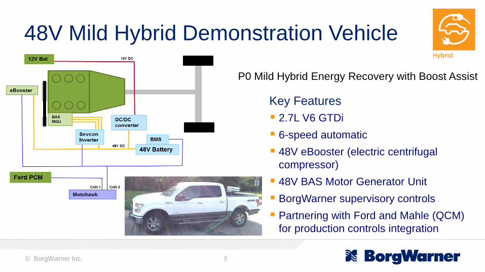
48V Mild Hybrid Demonstration Vehicle
Key Features
2.7L V6 GTDi
6-speed automatic
48V eBooster (electric centrifugal
compressor)
48V BAS Motor Generator Unit
BorgWarner supervisory controls
Partnering with Ford and Mahle (QCM)
for production controls integration
P0 Mild Hybrid Energy Recovery with Boost Assist
© BorgWarner Inc. 4
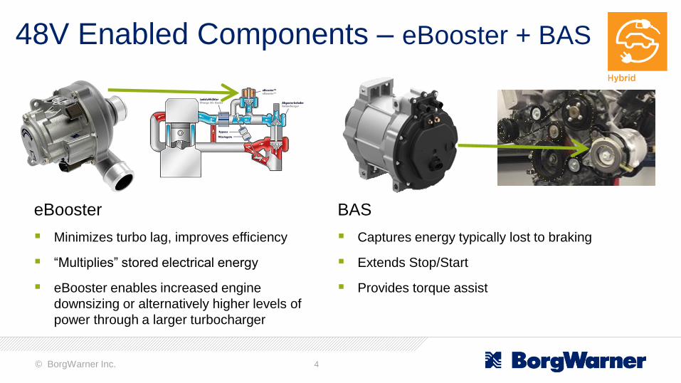
48V Enabled Components – eBooster + BAS
eBooster
Minimizes turbo lag, improves efficiency
“Multiplies” stored electrical energy
eBooster enables increased engine
downsizing or alternatively higher levels of
power through a larger turbocharger
BAS
Captures energy typically lost to braking
Extends Stop/Start
Provides torque assist

© BorgWarner Inc. 5
48V Vehicle Simulation Goals and Motivation
Motivation
• Allows investigation of major vehicle changes which would be cost prohibitive in hardware
• Model offers repeatable and controllable tests which allow quantification of fuel economy
benefit for subtle changes
Additional Goals
• Boosting system effects on fuel economy and performance
• Platform for controls development
• Fast simulation times which enable investigation using DOE techniques
Overall Goal
Development and usage of a 48V mild hybrid vehicle system level model for fuel economy studies

© BorgWarner Inc. 6
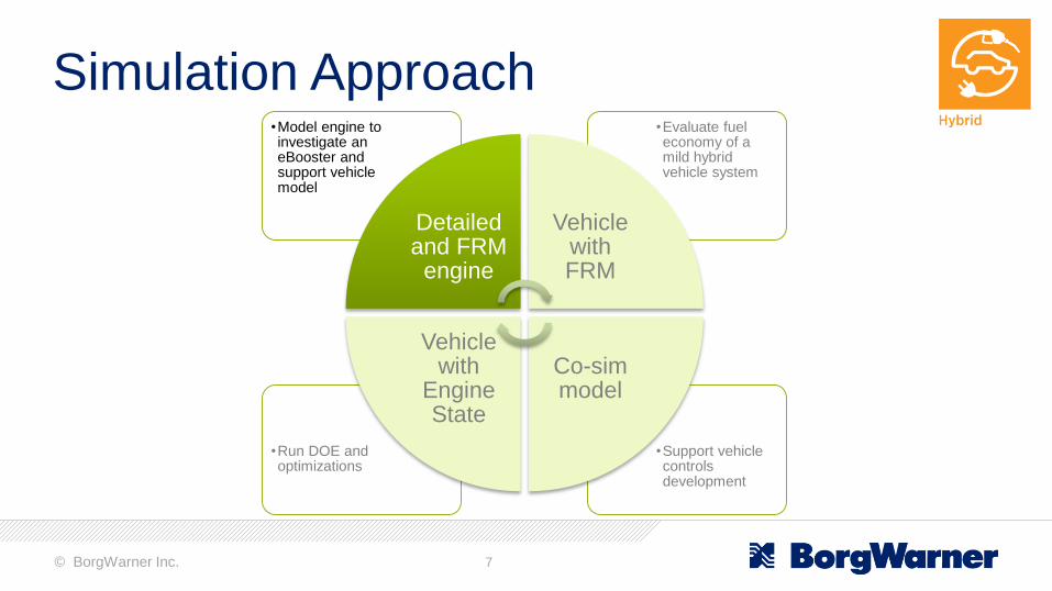
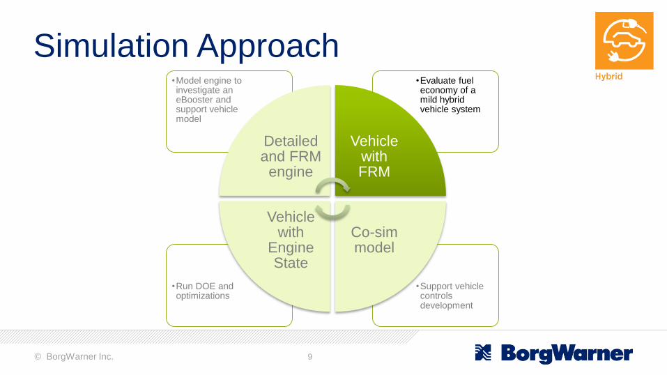
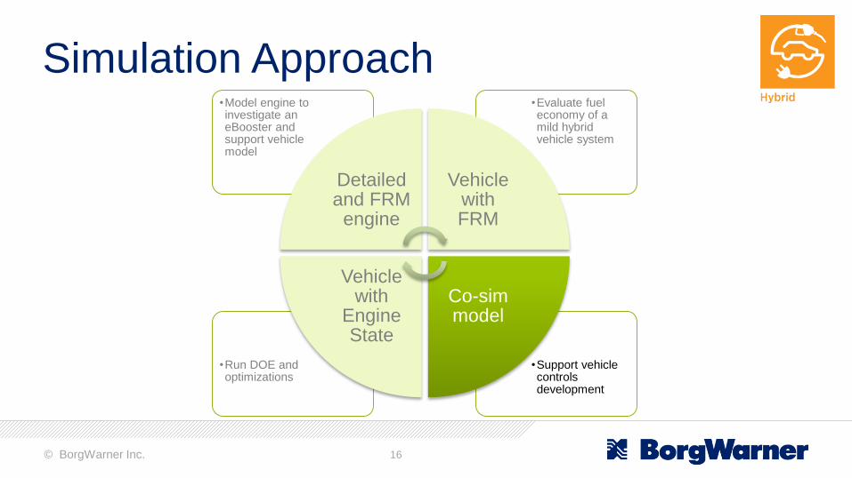
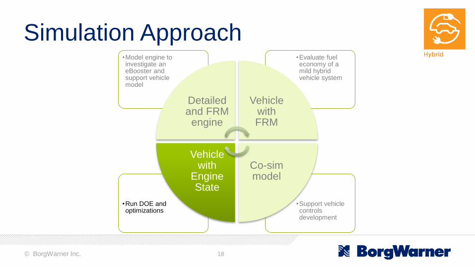
Simulation Approach
•Support vehicle controls development
•Run DOE and optimizations
•Evaluate fuel economy of a mild hybrid vehicle system
•Model engine to investigate an eBooster and support vehicle model
Detailed and FRM
engine
Vehicle with FRM
Co-sim model
Vehicle with
Engine State
4 Model Environments
© BorgWarner Inc. 7
Simulation Approach
•Support vehicle controls development
•Run DOE and optimizations
•Evaluate fuel economy of a mild hybrid vehicle system
•Model engine to investigate an eBooster and support vehicle model
Detailed and FRM
engine
Vehicle with FRM
Co-sim model
Vehicle with
Engine State
© BorgWarner Inc. 8
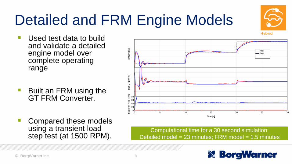
Detailed and FRM Engine Models Used test data to build
and validate a detailed engine model over complete operating range
Built an FRM using the GT FRM Converter.
Compared these models using a transient load step test (at 1500 RPM).
Computational time for a 30 second simulation:
Detailed model = 23 minutes; FRM model = 1.5 minutes
© BorgWarner Inc. 9
Simulation Approach
•Support vehicle controls development
•Run DOE and optimizations
•Evaluate fuel economy of a mild hybrid vehicle system
•Model engine to investigate an eBooster and support vehicle model
Detailed and FRM
engine
Vehicle with FRM
Co-sim model
Vehicle with
Engine State
© BorgWarner Inc. 10
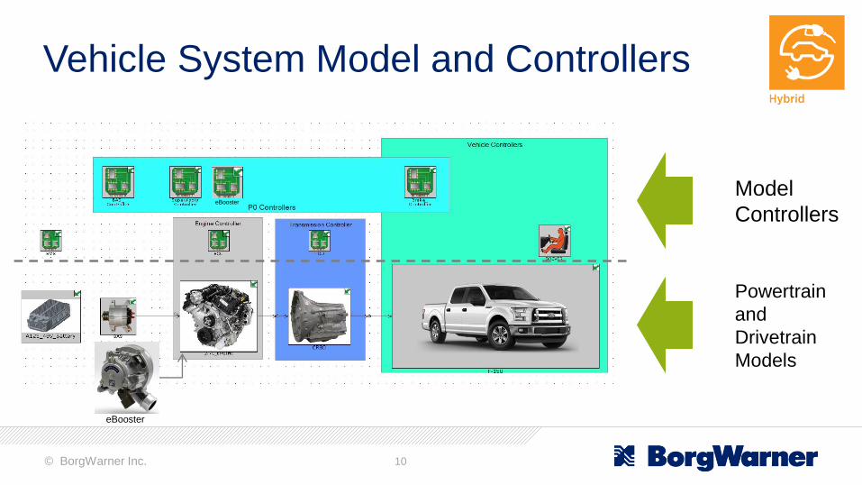
Vehicle System Model and Controllers
Model
Controllers
Powertrain
and
Drivetrain
Models
eBooster
eBooster

© BorgWarner Inc. 11
Controllers
eBooster
Engine – throttle, A/F ratio, spark, fuel-cut
Boost – waste gate
eBooster – electrical power
Transmission and torque converter – shifting and lock up
© BorgWarner Inc. 12
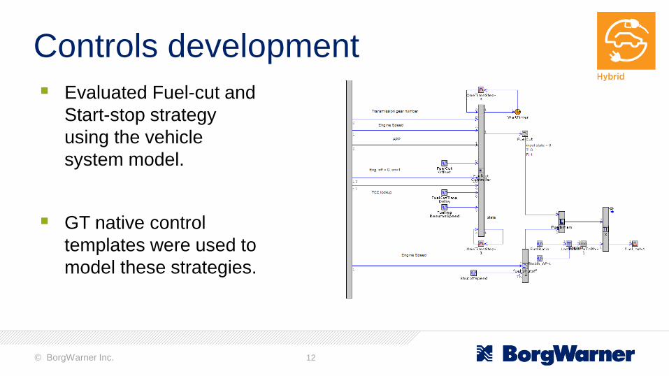
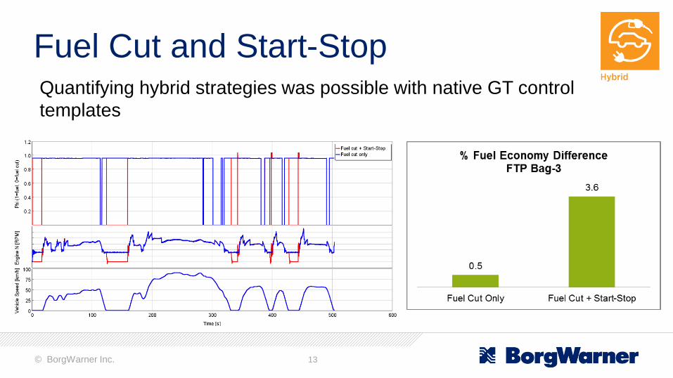
Controls development
Evaluated Fuel-cut and
Start-stop strategy
using the vehicle
system model.
GT native control
templates were used to
model these strategies.
© BorgWarner Inc. 13
Fuel Cut and Start-StopQuantifying hybrid strategies was possible with native GT control
templates
© BorgWarner Inc. 14
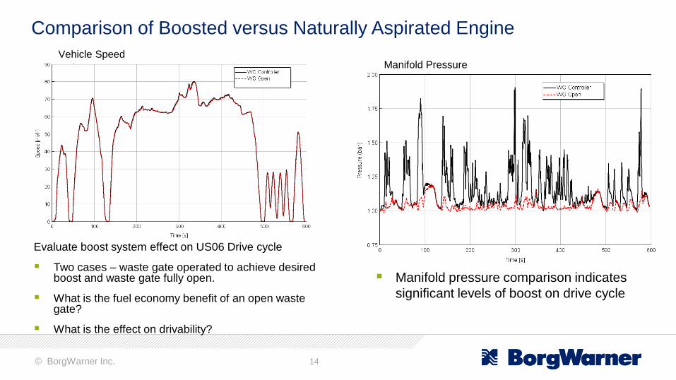
Comparison of Boosted versus Naturally Aspirated Engine
Evaluate boost system effect on US06 Drive cycle
Two cases – waste gate operated to achieve desired boost and waste gate fully open.
What is the fuel economy benefit of an open waste gate?
What is the effect on drivability?
Manifold pressure comparison indicates
significant levels of boost on drive cycle
Manifold PressureVehicle Speed

© BorgWarner Inc. 15
Power level can be achieved without boost system
There is a 3.5% fuel economy benefit
However, the fuel economy benefit comes with a drivability penalty
Comparison of Boosted versus Naturally Aspirated Engine
© BorgWarner Inc. 16
Simulation Approach
•Support vehicle controls development
•Run DOE and optimizations
•Evaluate fuel economy of a mild hybrid vehicle system
•Model engine to investigate an eBooster and support vehicle model
Detailed and FRM
engine
Vehicle with FRM
Co-sim model
Vehicle with
Engine State
© BorgWarner Inc. 17
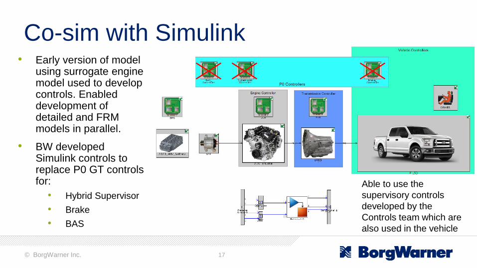
Co-sim with Simulink• Early version of model
using surrogate engine model used to develop controls. Enabled development of detailed and FRM models in parallel.
• BW developed Simulink controls to replace P0 GT controls for:
• Hybrid Supervisor
• Brake
• BAS
Able to use the
supervisory controls
developed by the
Controls team which are
also used in the vehicle
© BorgWarner Inc. 18
Simulation Approach
•Support vehicle controls development
•Run DOE and optimizations
•Evaluate fuel economy of a mild hybrid vehicle system
•Model engine to investigate an eBooster and support vehicle model
Detailed and FRM
engine
Vehicle with FRM
Co-sim model
Vehicle with
Engine State

© BorgWarner Inc. 19
Vehicle with Engine State Model
Replacement of FRM with Engine state reduces the simulation time by 99%
Generated shift schedules using the GT VKA analysis object
Evaluated effect of shift design variables on vehicle FE and drivability
DOE variables
Min speed following upshift
Max load following upshift
Engine speed at best FE position
Engine load at best FE position

© BorgWarner Inc. 20
Conclusions
1. Ability to develop models with appropriate levels of complexity
allowed timely analysis while achieving goals at all stages of
project.
2. FRM model capability to model air system with short run times
enabled evaluation of fuel economy versus drivability trade-off on
US06 drive cycle
3. Strong support from partners was a major factor in creation of high
fidelity models.
© BorgWarner Inc. 21
Acknowledgements
BorgWarner 48V Vehicle Demo Team: Keith Van Maanen, Matt Griffen,
John Shutty, Shawn Liu, Joel Maguire, Sara Mohon
Gamma Technologies: Jon Zeman and Joe Wimmer

© BorgWarner Inc. 22
Thank you!


