494 GAZETTE OFFICIELLE DU QUÉBEC, February 14, 2018, Vol. 150, No. 7 Part 2 Regulation respecting the extension of a storm water management system eligible for a declaration of compliance Environment Quality Act (chapter Q-2, s. 31.0.6, 2017, chapter 4) CHAPTER I APPLICATION 1. This Regulation applies to the design of the extension of a storm water management system eligible for a declaration of compliance. It determines, in Chapter II, the storm water management works that may be used to extend a storm water management system. It establishes, in Chapter III, the general design standards for the extension of a storm water management system and, in Chapter IV, the special design standards for storm water management works. CHAPTER II STORM WATER MANAGEMENT WORKS DIVISION I GENERAL 2. The following storm water management works may be used to extend the storm water management system: (1) the dry retention system described in Division II of Chapter II; (2) the permanent volume retention system described in Division III of Chapter II; (3) the grassed ditch described in Division IV of Chapter II; (4) the hydrodynamic separator described in Division V of Chapter II; (5) the commercial storm water treatment technology described in Division VI of Chapter II. DIVISION II DRY RETENTION SYSTEM 3. The purpose of a dry retention system is to reduce storm water flows passing through a storm water management system before being discharged in a receiving lake or watercourse and, where applicable, reduce the concentration of suspended matters in the water.
Transcript
494 GAZETTE OFFICIELLE DU QUÉBEC, February 14, 2018, Vol. 150, No. 7 Part 2
Regulation respecting the extension of a storm water management system eligible for a declaration of compliance Environment Quality Act (chapter Q-2, s. 31.0.6, 2017, chapter 4) CHAPTER I APPLICATION 1. This Regulation applies to the design of the extension of a storm water management system eligible for a declaration of compliance.
It determines, in Chapter II, the storm water management works that may be used to extend a storm water management system.
It establishes, in Chapter III, the general design standards for the
extension of a storm water management system and, in Chapter IV, the special design standards for storm water management works. CHAPTER II STORM WATER MANAGEMENT WORKS DIVISION I GENERAL 2. The following storm water management works may be used to extend the storm water management system:
(1) the dry retention system described in Division II of Chapter II; (2) the permanent volume retention system described in Division III of
Chapter II; (3) the grassed ditch described in Division IV of Chapter II; (4) the hydrodynamic separator described in Division V of Chapter II; (5) the commercial storm water treatment technology described in
Division VI of Chapter II. DIVISION II DRY RETENTION SYSTEM 3. The purpose of a dry retention system is to reduce storm water flows passing through a storm water management system before being discharged in a receiving lake or watercourse and, where applicable, reduce the concentration of suspended matters in the water.
rhean01
Texte surligné
Part 2 GAZETTE OFFICIELLE DU QUÉBEC, February 14, 2018, Vol. 150, No. 7 495
4. A dry retention system comprises
(1) a water and sediment accumulation zone;
(2) flow control devices;
(3) an emergency weir; and
(4) a maintenance access ramp.
5. A dry retention system that also reduces the concentration in suspended matters must include a pretreatment work and a microbasin.
A pretreatment work is not required if
(1) the storm water comes from a territory whose dominant use class is residential and is served by a road network whose annual average daily traffic is less than 500 vehicles; or
(2) the sum of the impervious surface drained to the dry retention system does not exceed 250 m².
6. A dry retention system is a system that must drain completely after the end of an exceptional rain vent, from the microbasin to the outlet.
7. A dry retention system governed by the Dam Safety Act (chapter S-3.1.01) is not a storm water management work for the purposes of this Regulation. DIVISION III PERMANENT VOLUME RETENTION SYSTEM 8. The purpose of a permanent volume retention system is to reduce storm water flows passing through a storm water management system before being discharged in a receiving lake or watercourse and, where applicable, reduce the concentration of suspended matters in the water.
9. A permanent volume retention system comprises
(1) a water and sediment accumulation zone;
(2) flow control devices;
(3) an emergency weir; and
(4) a maintenance access ramp.
10. A permanent volume retention system that also reduces the concentration of suspended matters must include a pretreatment work upstream from the system.
496 GAZETTE OFFICIELLE DU QUÉBEC, February 14, 2018, Vol. 150, No. 7 Part 2
A pretreatment system is not required if
(1) the storm water comes from a territory whose dominant use class is residential and is served by a road network whose annual average daily traffic is less than 500 vehicles; or;
(2) the sum of the impervious surface drained to the permanent volume retention system does not exceed 250 m².
11. A permanent volume retention system includes a permanent volume of water in the water and sediment accumulation zone above which there is a temporary volume of water in rainy weather that is drained gradually.
12. A permanent volume retention system governed by the Dam Safety Act (chapter S-3.1.01) is not a storm water management work for the purposes of this Regulation. DIVISION IV GRASSED DITCH 13. A grassed ditch is a ditch covered with vegetation and a geometry that allows the evacuation of storm water and maximises the reduction of the concentration of suspended matters in the water.
14. In a grassed ditch, storm water is drained downstream of the ditch by surface runoff. DIVISION V HYDRODYNAMIC SEPARATOR 15. A hydrodynamic separator is commercial equipment installed on a storm water management system to reduce the concentration of suspended matters in the storm water.
16. A hydrodynamic separator includes a tank in which a volume of water is present and components that promote the sedimentation of particles. DIVISION VI COMMERCIAL STORM WATER TREATMENT TECHNOLOGY 17. A commercial storm water treatment technology is commercial equipment, other than a hydrodynamic separator, installed on a storm water management system to reduce the concentration of suspended matters in the storm water.
Part 2 GAZETTE OFFICIELLE DU QUÉBEC, February 14, 2018, Vol. 150, No. 7 497
CHAPTER III DESIGN — EXTENSION OF A STORM WATER MANAGEMENT SYSTEM DIVISION I PLANS AND SPECIFICATIONS AND MAINTENANCE §1. ─ General
18. The design of the extension of a storm water management system must include the preparation of plans and specifications the general content of which is determined in subdivision 2 of Division I of Chapter III and a maintenance program the general content of which is determined in subdivision 3 of Division I of Chapter III.
The design must also include, where applicable, the preparation of plans and specifications and the maintenance program the contents of which are determined in subdivision 4 of Division III of Chapter III for supplementary storm water management works and the preparation of maintenance programs determined in Chapter IV for storm water management works. §2. ─ Plans and specifications 19. The plans and specifications must contain clauses requiring the contractor to
(1) carry out the work in accordance with the standard specification BNQ 1809-300 – Travaux de construction – Clauses techniques générales – Conduites d’eau potable et d’égout;
(2) prepare, for the duration of the work and according to the work phases, an erosion and sediment control program on the work site that includes
(a) measures to intercept storm water coming from outside the work site and maintain the water outside the work site;
(b) protection measures to prevent and avoid any soil loss caused by storm water;
(c) measures to drain storm water outside the work site;
(d) a plan that localizes the measures mentioned in subparagraphs a to c;
(3) implement measures to divert storm water from zones adjacent to the work site and prevent the water from passing on the work surfaces;
(4) isolate the work site so as to intercept suspended matters and any displacement of material;
(5) delimit the site zones and the material storage zones;
(6) delimit machinery traffic surfaces and protect them;
498 GAZETTE OFFICIELLE DU QUÉBEC, February 14, 2018, Vol. 150, No. 7 Part 2
(7) implement, for the duration of the work, measures to protect or cover bare soil, the granular material storage zones and steep slope zones against washout, gullying and transportation of particles during rainy weather;
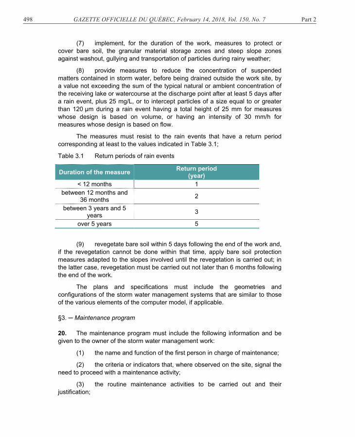
(8) provide measures to reduce the concentration of suspended matters contained in storm water, before being drained outside the work site, by a value not exceeding the sum of the typical natural or ambient concentration of the receiving lake or watercourse at the discharge point after at least 5 days after a rain event, plus 25 mg/L, or to intercept particles of a size equal to or greater than 120 µm during a rain event having a total height of 25 mm for measures whose design is based on volume, or having an intensity of 30 mm/h for measures whose design is based on flow.
The measures must resist to the rain events that have a return period corresponding at least to the values indicated in Table 3.1;
Table 3.1 Return periods of rain events
Duration of the measure Return period (year)
< 12 months 1 between 12 months and
36 months 2
between 3 years and 5 years 3
over 5 years 5
(9) revegetate bare soil within 5 days following the end of the work and, if the revegetation cannot be done within that time, apply bare soil protection measures adapted to the slopes involved until the revegetation is carried out; in the latter case, revegetation must be carried out not later than 6 months following the end of the work.
The plans and specifications must include the geometries and configurations of the storm water management systems that are similar to those of the various elements of the computer model, if applicable. §3. ─ Maintenance program 20. The maintenance program must include the following information and be given to the owner of the storm water management work:
(1) the name and function of the first person in charge of maintenance;
(2) the criteria or indicators that, where observed on the site, signal the need to proceed with a maintenance activity;
(3) the routine maintenance activities to be carried out and their justification;
Part 2 GAZETTE OFFICIELLE DU QUÉBEC, February 14, 2018, Vol. 150, No. 7 499
(4) a comprehensive inventory of problematic situations that may be encountered and their solution;
(5) a schedule and frequency of the maintenance activities to be carried out;
(6) an estimate of the costs to carry out the maintenance activities and the costs for disposal of debris, waste and sediments;
(7) the equipment, tools and material required for the maintenance or repair activities and, if specific tools must be used, a list of suppliers of those tools;
(8) the instructions for the maintenance and replacement of the parts of the hydrodynamic separators and commercial storm water treatment technologies;
(9) the identification of the training or certificates required for the staff responsible for carrying out the maintenance activities;
(10) the procedures and equipment required to ensure the safety of the staff carrying out the maintenance activities;
(11) the identification of the places for the disposal or reclamation of residual materials and the criteria to be met where the sludge is reclaimed;
(12) a copy of the warranties of the manufacturers of the hydrodynamic separators and commercial storm water treatment technologies;
(13) a copy of the construction plans of the storm water management works. DIVISION II DIMENSIONING §1. ─ General 21. To determine the runoff peak flow of a territory or the storage volume of a storm water management work, the rational method or computer model complying with the standards established in subdivision 4 of Division II of Chapter III must be used.
The rational method described in subdivision 2 of Division II of Chapter III allows the estimating of the runoff peak flow of a territory having an area less than 25 km2 for storm water management works whose design criterion is the runoff flow.
The rational method described in subdivision 3 of Division II of Chapter III allows the estimating of the storage volume of a storm water management work whose design criterion is the runoff volume receiving storm water from a territory having a maximum area of 5 ha.
500 GAZETTE OFFICIELLE DU QUÉBEC, February 14, 2018, Vol. 150, No. 7 Part 2
For the other hydrological and hydraulic calculations provided for in this Regulation, a computer model may be used if the standards established in subdivision 4 of Division II of Chapter III are complied with.
For the purposes of this Regulation,
(1) the grassed ditch, the hydrodynamic separators and the commercial storm water treatment technologies are storm management works whose design criterion is the runoff flow;
(2) the dry retention system and the permanent volume retention system are storm management works whose design criterion is the runoff volume.
22. When, in the application of the rational method or a computer model, intensity-duration-frequency values of the rainfalls are used, the values must result from the statistical analysis of the rainfall data from a weather station whose rain conditions and altitude are representative of those prevailing in the territory drained to the storm water management system and have been produced by Environment Canada, Agrométéo Québec or a municipality.
The intensity-duration-frequency values of rainfalls associated with a return period must be based on a number of years of recording rainfall data complying with the number of years of recording indicated in Table 3.2.
Table 3.2 Number of years of recording associated with a return period
Return period Number of years of recording < 2 years 5 2 years 5
10 years 10 25 years 15 50 years 20 100 years 25
For every hydrological calculation carried out with projected conditions, the intensity-duration-frequency values of the rainfalls must be increased by the minimum value indicated in Table 3.3 on the basis of the return period.
Table 3.3 Increase
Return period Increase < 2 years No increase ≥ 2 years + 18%
§2. ─ Rational method/Runoff flow
23. The runoff peak flow, Q, of storm water management works whose design criterion is the runoff flow is established using equation 3-1.
Equation 3-1: Q = Cr(p) × A × i/360
Part 2 GAZETTE OFFICIELLE DU QUÉBEC, February 14, 2018, Vol. 150, No. 7 501
where:
Q = Runoff peak flow (m³/s);
Cr(p) = Weighted runoff coefficient established using equation 3-2;
A = Area of the territory draining to the storm water management work (ha);
i = Rain intensity (mm/h);
360 = Conversion coefficient for units.
Equation 3-2: ����� � ∑ ������������∑ ������� �
where:
Cr(p) = Weighted runoff coefficient;
Aj = Area of the homogenous surface j (m²);
Crj = Runoff coefficient in relation to the homogenous surface j;
m = Number of homogenous surfaces included in the territory draining to the water storm management system.
24. The following rules apply to the factors of equations 3-1 and 3-2:
(1) the runoff coefficients Crj used may not be less than the values indicated in Table 3.4;
Table 3.4 Runoff coefficients Crj according to the various types of surface return periods
Surface Return period
2 to 10 years
11 to 25 years
26 to 50 years
51 to 100 years
Gravel Compacted (unpaved road, shoulder, etc.) Non compacted
0.750.60
0.83 0.66
0.95 0.79
0.95 0.95
Paving Asphalt, concrete Bricks Permeable
0.900.800.05
0.95 0.88 0.06
0.95 0.95 0.07
0.95 0.95 0.08
Conventional roof 0.95 0.95 0.95 0.95 Green roof Thickness < 100 mm Thickness from 100 to 200 mm Thickness from 200 to 500 mm Thickness > 500 mm
0.500.300.200.10
0.55 0.33 0.22 0.11
0.66 0.40 0.26 0.13
0.83 0.50 0.33 0.17
502 GAZETTE OFFICIELLE DU QUÉBEC, February 14, 2018, Vol. 150, No. 7 Part 2
Grass (sandy soil) Flat (slope < 2%) Average (slope of 2 to 7%) Steep (slope > 7%)
0.080.130.18
0.09 0.14 0.20
0.11 0.17 0.24
0.13 0.21 0.30
Grass (dense soil) Flat (slope < 2%) Average (slope from 2 to 7%) Steep (slope > 7%)
0.150.200.30
0.17 0.22 0.33
0.20 0.26 0.40
0.25 0.22 0.50
(2) the rain intensity, i, to be used is the intensity associated with a rainfall duration equal to the concentration time, tc, of the territory drained to the storm water management system established using equation 3-3 and associated with the return period considered.
Equation 3-3 tc= max(te + tf)
where
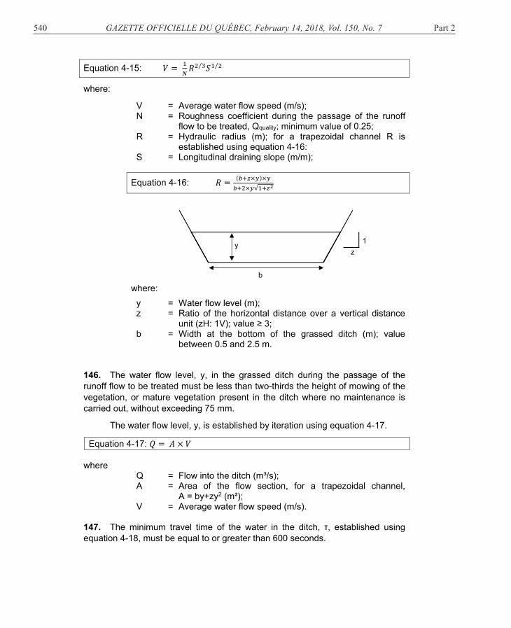
tc = Concentration time (min); te = Entry time established using equation 3-4 (min); tf = Water flow time in the storm water management system
(min); max = Function of maximization indicating that the
concentration time corresponds to the time associated with the combination of an entry time, te, and a water flow time, tf, in the storm water management system for which the sum is the highest.
Equation 3-4: �� � ����������√� ������ where:
te = Entry time (min); L = Maximum distance covered by the water at the surface
before reaching the intake of the storm water management system (m); maximum value: 365 m;
N = Roughness coefficient of the sheet flow according to the flow surfaces indicated in Table 3.5 (s/m1/3);
S = Average slope of the path travelled by the water before reaching the intake of the storm water management system (m/m).
Part 2 GAZETTE OFFICIELLE DU QUÉBEC, February 14, 2018, Vol. 150, No. 7 503
Table 3.5 Roughness coefficients
Flow surface Roughness coefficient Asphalt/concrete 0.01 to 0.15 Smooth impervious surface 0.02 Bare soil, compacted, without debris, without rocks 0.10
Short and sparse vegetation 0.05 Cultivated soil Surface of residues ≤ 20% Surface of residues > 20%
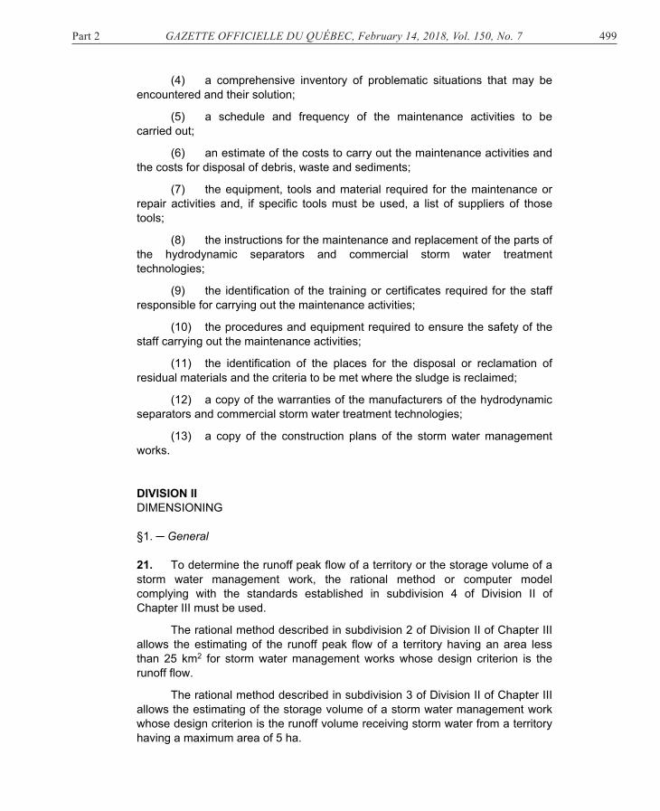
25. The following rules apply to factor, tf, of equation 3-3:
(1) the water flow time, tf, for a storm water management system constituted of ditches is established using equation 3-5:
Equation 3-5: �� � � ����� �⁄ �√�� ����
where:
tf = Water flow time in the storm water management system constituted of ditches (min);
L = Length of water flow into ditches between the intake and the connection point to the storm water management system (m);
n = Manning’s coefficient of the ditches determined in Table 3.6 (s/m1/3);
R = Hydraulic radius of the ditch established by assuming that the design flow flows into the ditch. If a number of ditch geometries are present on the route, L, the geometry showing the highest hydraulic radius value must be used (m);
S = Average slope of water flow (m/m); 60 = Conversion coefficient for the units.
504 GAZETTE OFFICIELLE DU QUÉBEC, February 14, 2018, Vol. 150, No. 7 Part 2
Table 3.6 Manning’s coefficients
Type of ditch Manning’s coefficient Unprotected ditches A) Earth
Without vegetation Grassed Sparse bush Dense bush
B) Rock Smooth and even Irregular with roughness
0.018 0.025 0.080 0.120
0.038 0.043
Protected ditches A) Concrete
Unfinished concrete Finishing
B) Concrete apron Stone and mortar walls Concrete block walls Armour stone walls (riprap)
C) Gravel apron Concrete walls Stone and mortar walls Armour stone walls (riprap)
D) Brick E) Bituminous concrete F) Wood
0.015 0.013
0.018 0.023 0.025
0.019 0.022 0.028 0.016 0.015 0.012
Road and drainage ditches A) Depth < 200 mm
Grass 50 mm Grass from 100 to 150 mm Hay 300 mm Hay 600 mm
B) Depth from 200 to 450 mm Grass 50 mm Grass from 100 to 150 mm Hay 300 mm Hay 600 mm
0.058 0.070 0.130 0.215
0.043 0.050 0.105 0.145
(2) the water flow time, tf, for a storm water management system constituted of pipes is established using equation 3-6:
Part 2 GAZETTE OFFICIELLE DU QUÉBEC, February 14, 2018, Vol. 150, No. 7 505
Equation 3-6: �� � ����������� �⁄ �√� � ����
where
tf = Water flow time in the storm water management system constituted of pipes (min);
L = Length of water flow into the pipe between the intake and the connection point to the storm water management system (m);
n = Manning’s coefficient of the pipes determined in Table 3.7 (s/m1/3);
D = Diameter of the pipe (m). If a number of pipes are present on the route, L, an average diameter must be used;
S = Average slope of water flow (m/m); 60 = Conversion coefficient for the units.
Table 3.7 Manning’s coefficients
Type of pipe Roughness or corrugation Manning’s coefficient
Corrugated steel pipe Annular or helical corrugations
68 over 13 mm (annular) Unpaved 25% paved 100% paved 68 over 13 mm (helical) Unpaved 25% paved 100% paved 76 over 25 mm (annular) Unpaved 25% paved 100% paved 76 over 25 mm (helical) 150 over 25 mm 125 over 25 mm 75 over 25 mm 150 over 50 mm
506 GAZETTE OFFICIELLE DU QUÉBEC, February 14, 2018, Vol. 150, No. 7 Part 2
§3. ─ Rational method/Runoff volume
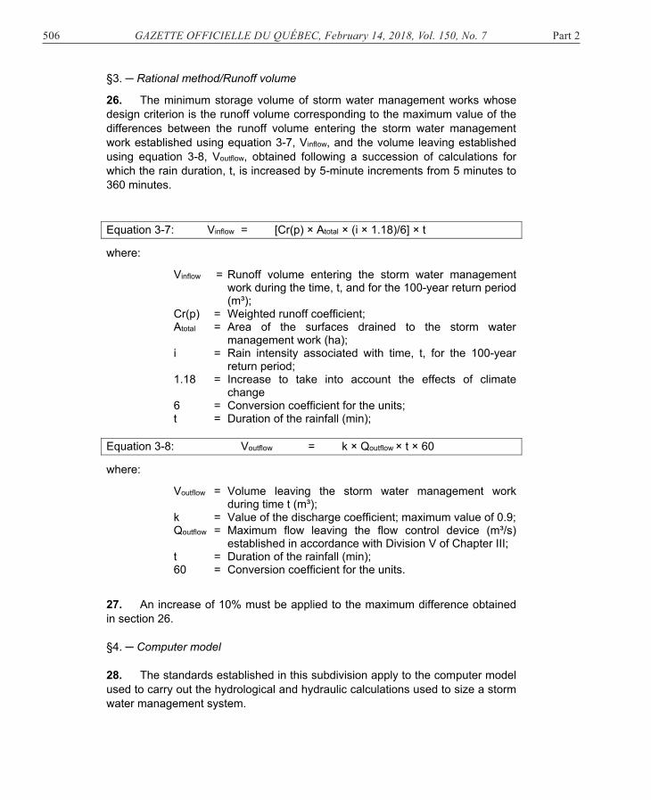
26. The minimum storage volume of storm water management works whose design criterion is the runoff volume corresponding to the maximum value of the differences between the runoff volume entering the storm water management work established using equation 3-7, Vinflow, and the volume leaving established using equation 3-8, Voutflow, obtained following a succession of calculations for which the rain duration, t, is increased by 5-minute increments from 5 minutes to 360 minutes.
Equation 3-7: Vinflow = [Cr(p) × Atotal × (i × 1.18)/6] × t
where:
Vinflow = Runoff volume entering the storm water management work during the time, t, and for the 100-year return period (m³);
Cr(p) = Weighted runoff coefficient; Atotal = Area of the surfaces drained to the storm water
management work (ha); i = Rain intensity associated with time, t, for the 100-year
return period; 1.18 = Increase to take into account the effects of climate
change 6 = Conversion coefficient for the units; t = Duration of the rainfall (min);
Equation 3-8: Voutflow = k × Qoutflow × t × 60
where:
Voutflow = Volume leaving the storm water management work during time t (m³);
k = Value of the discharge coefficient; maximum value of 0.9; Qoutflow = Maximum flow leaving the flow control device (m³/s)
established in accordance with Division V of Chapter III; t = Duration of the rainfall (min); 60 = Conversion coefficient for the units.
27. An increase of 10% must be applied to the maximum difference obtained in section 26. §4. ─ Computer model
28. The standards established in this subdivision apply to the computer model used to carry out the hydrological and hydraulic calculations used to size a storm water management system.
Part 2 GAZETTE OFFICIELLE DU QUÉBEC, February 14, 2018, Vol. 150, No. 7 507
29. The computer model must be based on the calculation processes and algorithms of modelling software SWMM5, Storm Water Management Model, developed by the American agency Environmental Protection Agency.
30. The parameters of the computer model must comply with the values of the attributes indicated in Table 3.8 for the parameter “General options”.
For the other parameters of the computer model, the values of the attributes, other than the Horton attribute, must be determined following a calibration of the model or, failing that, comply with the values indicated in Table 3.8.
For the values of the Horton attribute, if onsite data are available, the date must be used or, failing that, the values indicated in Table 3.8 must be complied with.
Table 3.8 Parameters of the SWMM5 computer model
Parameter of the model
Attributes Value
General options Units
L/s or m³/s
General options Routing model
Dynamic wave
General options Infiltration model
Horton
General options Reporting time steps
≤ 1 minute
General options Routing time steps
≤ 30 seconds
General options Allow ponding Activated
Subcatchments Roughness coefficient (N) – impervious area
Table 3.5
Subcatchments Roughness coefficient (N) – pervious area
Subcatchments Depth of depression storage – impervious area
Table 3.9
Subcatchments Depth of depression storage – pervious area
508 GAZETTE OFFICIELLE DU QUÉBEC, February 14, 2018, Vol. 150, No. 7 Part 2
Subcatchments Horton – maximum infiltration rate (f0)
Table 3.9 Initial losses according to the type of surfaces
Type of surface Minimum initial loss (mm)
Paving 1.5
Flat roof 1.5
Sloped roof 1.0
Grass 5.0
Wooded area and fields 8.0
Forest 15.0
Table 3.10 Initial infiltration capacity
Type of surface
Initial infiltration capacity (mm/h)
With little or no vegetation With dense vegetation
Sandy soil Loam Clay soil
Sandy soil Loam Clay
soil
Dry soil 125 75 25 250 150 50
Wet soil (drained
soil but not dry)
40 25 10 80 50 15
Wet soil (saturated soil)
Values of Table 3.11
Wet soil (partially saturated
soil)
60 40 15 125 75 25
Part 2 GAZETTE OFFICIELLE DU QUÉBEC, February 14, 2018, Vol. 150, No. 7 509
Table 3.11 Ultimate infiltration capacity
Hydrologic soil group (1) Ultimate infiltration capacity (mm/h)
A 7.5 to 11.4
B 3.8 to 7.5
C 1.3 to 3.8
D 0.0 to 1.3
(1) Hydrologic groups A, B, C and D are those defined in the report Classement des séries de sols minéraux du Québec selon les groupes hydrologiques, Rapport final, IRDA, déc. 2013.
31. The simulation model of a storm water management system must be a double drain construction.
A simulation model is a double drain construction where the minor and major drainage systems of the storm water management system are modellized and the surcharges of the minor drainage system and the interaction between the major and minor drainage systems are taken into consideration.
A minor drainage system intercepts, carries and discharges storm water from events having a return period less than 25 years and, where applicable, treats, holds and controls storm water flow: it comprises storm water management works, ditches, pipes, sumps and manholes.
A major drainage system allows the flow of surface storm water where the capacity of the minor drainage system is exceeded.
32. The characteristics of each modellized sub-basins in a computer model must be homogenous for the sub-basin modellized.
33. The duration of the simulation must end, at least, at the end of the simulated storm pattern plus 48 hours.
A storm pattern is rain that is integrated to the computer model for hydrological and hydraulic simulation purposes.
34. The continuity errors on the mass conservation of the runoff water model and water flow model must be between 5% and +5% at the end of a simulation.
35. Where simulated rain intensities or levels have return periods equal to or less than the service level of a simulated minor drainage system, no “node” type element of the computer model may be flooded on the surface for the duration of the simulation.
510 GAZETTE OFFICIELLE DU QUÉBEC, February 14, 2018, Vol. 150, No. 7 Part 2
The service level of the minor drainage system is the annual probability that part or all of the minor network flow surcharges and corresponds to the return period according to T = 1/P where T is the return period in years and P is the annual probability that part or all of a minor network flow surcharges at least once.
36. No hydrographs of the “segment” type element of the computer model must have digital instabilities at the end of a simulation that affect the validity of the results.
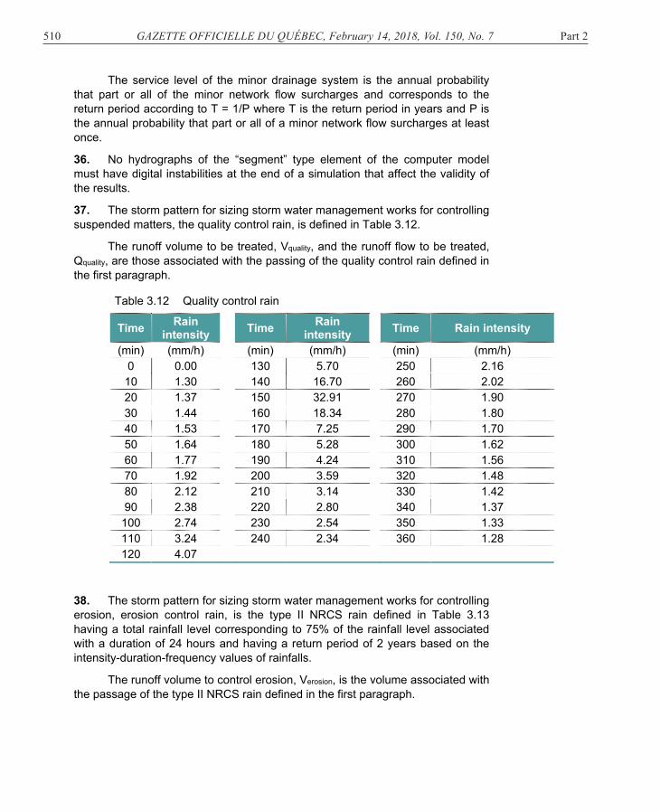
37. The storm pattern for sizing storm water management works for controlling suspended matters, the quality control rain, is defined in Table 3.12.
The runoff volume to be treated, Vquality, and the runoff flow to be treated, Qquality, are those associated with the passing of the quality control rain defined in the first paragraph.
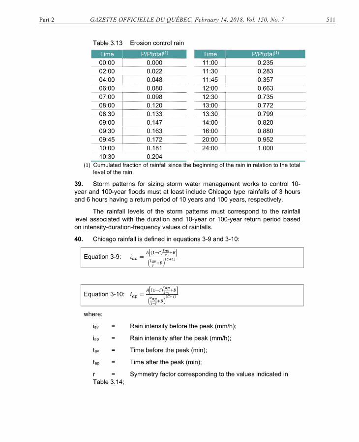
38. The storm pattern for sizing storm water management works for controlling erosion, erosion control rain, is the type II NRCS rain defined in Table 3.13 having a total rainfall level corresponding to 75% of the rainfall level associated with a duration of 24 hours and having a return period of 2 years based on the intensity-duration-frequency values of rainfalls.
The runoff volume to control erosion, Verosion, is the volume associated with the passage of the type II NRCS rain defined in the first paragraph.
Part 2 GAZETTE OFFICIELLE DU QUÉBEC, February 14, 2018, Vol. 150, No. 7 511
(1) Cumulated fraction of rainfall since the beginning of the rain in relation to the total level of the rain.
39. Storm patterns for sizing storm water management works to control 10-year and 100-year floods must at least include Chicago type rainfalls of 3 hours and 6 hours having a return period of 10 years and 100 years, respectively.
The rainfall levels of the storm patterns must correspond to the rainfall level associated with the duration and 10-year or 100-year return period based on intensity-duration-frequency values of rainfalls.
40. Chicago rainfall is defined in equations 3-9 and 3-10:
Equation 3-9:
Equation 3-10:
where:
iav = Rain intensity before the peak (mm/h);
iap = Rain intensity after the peak (mm/h);
tav = Time before the peak (min);
tap = Time after the peak (min);
r = Symmetry factor corresponding to the values indicated in Table 3.14;
512 GAZETTE OFFICIELLE DU QUÉBEC, February 14, 2018, Vol. 150, No. 7 Part 2
A,B,C = Regression coefficients of the intensity-duration-frequency curve defined in equation 3-11.
Equation 3-11: i = A/(B+t)C
where:
i = Rain intensity (mm/h);
t = Duration of the rain (min).
Table 3.14 Symmetry factor
Place Symmetry factor (r)
Montréal 0.45
Lennoxville 0.37
Val d’Or 0.38
Québec 0.38
La Pocatière 0.42
Normandin 0.32
Bagotville 0.42
Other 0.40
41. The time step of the hyetograph of a rain pattern must comply with the durations indicated in Table 3.15.
Table 3.15 Duration of the time step of the hyetograph of a rain pattern
Type of rainfall Duration of the time step of the hyetograph (min)
Chicago 10 NRCS type II 15
42. Where more than one rain pattern is used to design storm water management works, the patterns must be simulated and the results leading to the largest sizing of the storm water management works must be kept for design purposes.
Part 2 GAZETTE OFFICIELLE DU QUÉBEC, February 14, 2018, Vol. 150, No. 7 513
DIVISION III REDUCTION OF SUSPENDED MATTERS §1. ─ General 43. To reach the goal of reducing suspended matters, the design of the extension of a storm water management system must
(1) comply with the design standards of storm water management works provided for in subdivision 2 of Division III of Chapter III and apply the calculation standards determined therein to assess the suspended matter reduction performance of storm water management works;
(2) allow the treatment of the runoff volume or flow associated with the quality control rain in accordance with subdivision 3 of Division III of Chapter III;
(3) comply, where aplicable, with the design standards of certain works supplementary to the storm water management works referred to in subdivision 4 of Division III of Chapter III. §2. ─ Storm water management works
44. Storm water management works must be installed in increasing order of their suspended matter reduction performance, from upstream to downstream, except hydrodynamic separators that must be installed upstream from a treatment chain.
45. Two storm water management works of the same type may not be installed in series to increase the suspended matter reduction performance.
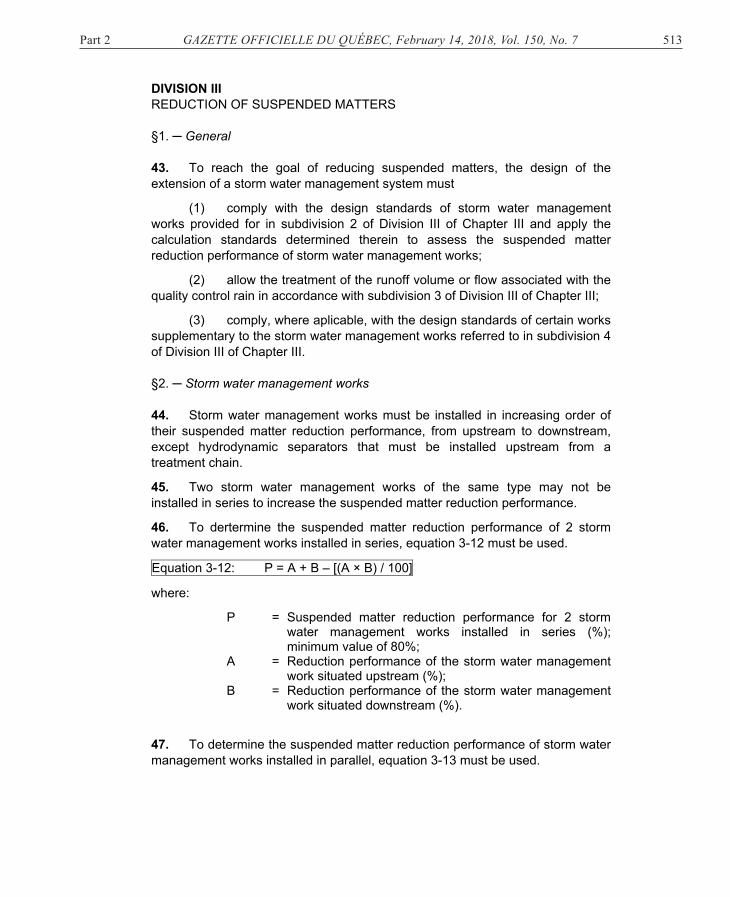
46. To dertermine the suspended matter reduction performance of 2 storm water management works installed in series, equation 3-12 must be used.
Equation 3-12: P = A + B – [(A × B) / 100]
where:
P = Suspended matter reduction performance for 2 storm water management works installed in series (%); minimum value of 80%;
A = Reduction performance of the storm water management work situated upstream (%);
B = Reduction performance of the storm water management work situated downstream (%).
47. To determine the suspended matter reduction performance of storm water management works installed in parallel, equation 3-13 must be used.
514 GAZETTE OFFICIELLE DU QUÉBEC, February 14, 2018, Vol. 150, No. 7 Part 2
Equation 3-13: � � � � ∑ ������������∑ ������
where:
P = Suspended matter reduction performance of n storm water management works installed in parallel (%); minimum value of 80%;
Qi = Flow passing through the work i (m³/s); ri = Suspended matter reduction performance of storm water
management work i determined in accordance with Table 3.16 (%).
Table 3.16 Suspended matter reduction performance
Storm water management works Suspended matter
reduction performance
Dry retention system
40 to 60%: performance established in
accordance with subdivision 2 of
Division I of Chapter IV
Permanent volume retention system
50 to 90%: performance established in
accordance with subdivision 2 of
Division II of Chapter IV
Grassed ditch
50% or performance established in section 148
Hydrodynamic separator
Variable: performance established in
accordance with Division IV of Chapter IV
Commercial storm water treatment technology
50% or 80%: performance established in
accordance with Division V of Chapter IV
Part 2 GAZETTE OFFICIELLE DU QUÉBEC, February 14, 2018, Vol. 150, No. 7 515
§3. ─ Design flow or volume 48. Water management works must be designed to treat the runoff volume or flow associated with the quality control rain whether the design of the work is based on a runoff volume or flow.
The quality control rain for a storm water management work whose design is based on a runoff volume is rainfall having a total rainfall level of 25 mm.
The quality control rain for a storm water management work whose design is based on a runoff flow is rainfall having an average rain intensity corresponding to 65% of the rain intensity having a 2-year return period based on rainfall intensity-duration-frequency data for a duration that may not exceed the concentration time of the territory draining to a storm water management work established using equation 3-3.
49. The runoff volume to be treated from the territory draining to a storm water management work whose design criterion is the runoff volume is established using equation 3-14.
Equation 3-14: Vquality = 25 × 0.9 × Aimp × 10
where:
Vquality = Runoff volume to be treated (m³); 25 = Quality control rain level (mm); 0.9 = Runoff coefficient; Aimp = Sum of impervious surfaces drained to the storm water
management work, including surfaces drained indirectly (ha);
10 = Conversion coefficient for the units.
50. The runoff flow to be treated from the territory draining to a storm water management work whose design criterion is the runoff flow is established using equation 3-15.
where: Qquality = Runoff flow to be treated (m³/s); 0.65 = Rainfall level adjustment factor;
i2years = Rain intensity having a 2-year return period based on the rainfall intensity-duration-frequency values for a duration that may not exceed the concentration time of the territory draining to a storm water management work (mm/h);
0.9 = Associated runoff coefficient; Aimp = Sum of impervious surfaces drained to the storm water
management work, including surfaces drained indirectly (ha);
360 = Conversion coefficient for the units.
516 GAZETTE OFFICIELLE DU QUÉBEC, February 14, 2018, Vol. 150, No. 7 Part 2
§4. ─ Supplementary storm water management works 1. REVEGETATION 51. The plant species listed in Schedule I may not be used in the design of the extension of a storm water management system.
52. Where plants are provided for in the design of the extension of a storm water management system, the plants chosen must be adapted to the hydrological zone indicated in Table 3.17.
The hydrological zones correspond to those listed in Table 3.18.
Table 3.17 Hydrological zones
Storm water management work
Hydrological zone
1 2 3 4 5
Dry retention system X X X
Permanent volume retention system X X X X X
Grassed ditch X X X
Table 3.18 Description of hydrological zones
Zone Description Hydrological conditions
1 Permanent deep water
Permanent presence of water; Water depth > 0.5 m; Aquatic plants appropriate for the greatest depths.
2 Permanent shallow water
Permanent presence of water; Water depth from 0.15 to 0.5 m.
3 Retention zone
Exposed zone between 2 rain events, but regularly flooded;
For a dry retention system and a grassed ditch, the zone corresponds to the zone between the bottom and the water level reached following the passage of the erosion control rain defined in section 77;
For a permanent volume retention system, the zone corresponds to the permanent volume water level in the water and sediment accumulation zone and the level reached by the water following the passage of the erosion control rain defined in section 77.
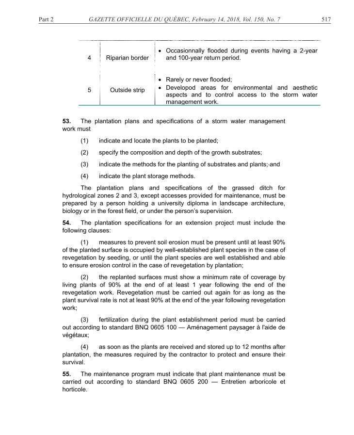
Part 2 GAZETTE OFFICIELLE DU QUÉBEC, February 14, 2018, Vol. 150, No. 7 517
4 Riparian border Occasionnally flooded during events having a 2-year
and 100-year return period.
5 Outside strip Rarely or never flooded; Developod areas for environmental and aesthetic
aspects and to control access to the storm water management work.
53. The plantation plans and specifications of a storm water management work must
(1) indicate and locate the plants to be planted;
(2) specify the composition and depth of the growth substrates;
(3) indicate the methods for the planting of substrates and plants; and
(4) indicate the plant storage methods.
The plantation plans and specifications of the grassed ditch for hydrological zones 2 and 3, except accesses provided for maintenance, must be prepared by a person holding a university diploma in landscape architecture, biology or in the forest field, or under the person’s supervision.
54. The plantation specifications for an extension project must include the following clauses:
(1) measures to prevent soil erosion must be present until at least 90% of the planted surface is occupied by well-established plant species in the case of revegetation by seeding, or until the plant species are well established and able to ensure erosion control in the case of revegetation by plantation;
(2) the replanted surfaces must show a minimum rate of coverage by living plants of 90% at the end of at least 1 year following the end of the revegetation work. Revegetation must be carried out again for as long as the plant survival rate is not at least 90% at the end of the year following revegetation work;
(3) fertilization during the plant establishment period must be carried out according to standard BNQ 0605 100 — Aménagement paysager à l'aide de végétaux;
(4) as soon as the plants are received and stored up to 12 months after plantation, the measures required by the contractor to protect and ensure their survival.
55. The maintenance program must indicate that plant maintenance must be carried out according to standard BNQ 0605 200 — Entretien arboricole et horticole.
518 GAZETTE OFFICIELLE DU QUÉBEC, February 14, 2018, Vol. 150, No. 7 Part 2
56. The maintenance program must indicate that the maintenance activities, except mowing activites, must be carried out or supervised by
(1) a contractor that is a member of the l’Association des paysagistes professionnels du Québec inc.;
(2) a holder of a college diploma in landscaping and groundskeeping in ornamental horticulture;
(3) a holder of a vocational studies diploma in horticulture and garden centre operations;
(4) a person with a continuing work experience of a minimun of 2 years in plant maintenance under the supervision of one of the persons referred to in the preceding paragraphs. 2. PRETREATMENT WORK 57. The purpose of a pretreatment work is to collect particles at least 65 µm contained in storm water before they enter in a storm water management work.
The following are pretreatment works: the hydrodynamic separator, the grassed ditch and the pretreatment cell.
58. Every pretreatment work must be situated upstream of storm water management works.
59. Preteatment works are classified in the following 2 levels:
(1) level 1 allows the withdrawal of at least 35% of suspended matters or removal of particles at least 120 µm during the passage of the runoff flow to be treated;
(2) level 2 allows the withdrawal of at least 50% of suspended matters or removal of particles at least 65 µm during the passage of the runoff flow to be treated.
The hydrodynamic separator is a level 1 or level 2 pretreatment work depending on the performance associated with the treatment flow of the selected model determined under Division IV of Chapter IV, and the grassed ditch and pretreatment cell are a level 2.
60. A level 1 or level 2 pretreatment work must be installed for each intake of the dry retnetion system or the permanent volume retention system whose purpose is to reduce suspended matters through which travels storm water from at least 10% of the surfaces drained by the dry retention system or the permanent volume retention system.
Part 2 GAZETTE OFFICIELLE DU QUÉBEC, February 14, 2018, Vol. 150, No. 7 519
3. PRETREATMENT CELL 61. A pretreatment cell is a water basin in which particles greater than 65 µm contained in runoff water settle.
It is separated from the storm water management work by a barrier.
62. The barrier separating a pretreatment cell from the storm water management work must allow the distribution of water over the full width of the water and sediment accumulation zone.
If a granular berm is used as barrier, it must be protected from erosion.
63. A pretreatement cell of a dry retention system must be empty at least 48 hours after the end of the rain event if no other rain event occurs during that period.
A rain event is an event characterized by the recording of rainfall data following a continuous period of at least 6 hours during which the total rainfall level does not exceed 0.3 mm.
64. The water level in the pretreatment cell must not exceed 1 metre.
65. The water flow speed in the pretreatment cell must be less than 1.2 m/s during the passage of the peak flow having a 2-year return period.
66. A layout allowing the complete emptying of the pretreatment cell or the drainage of water using a removable pump must be provided for.
67. The storage capacity of pretreatment cells for the accumulation of sediments and water must correspond to at least 15% of the runoff volume to be treated. The volume must be distributed proportionally between the tributary surfaces of each pipe.
68. The storage capacity of pretreatment cells must be increased by 20% if sand or other aggregate is used in winter as abrasive in the territory draining to the dry retention system or the permanent volume retention system.
69. Half the storage capacity calculated in section 67 must be reserved for the accumulation of sediments.
70. The pretreatment cell must be equipped with an access for the maintenance machinery. If an access ramp is installed, it must comply with the layout standards provided for in section 92.
71. A sediment accumulation level indicator must be installed in the pretreatment cell and have a mark indicating the level reached by the sediment volume determined in section 69.
520 GAZETTE OFFICIELLE DU QUÉBEC, February 14, 2018, Vol. 150, No. 7 Part 2
4. MICROBASIN 72. A microbassin is a depressed cavity situated downstream of the dry retention system allowing the maintenance of a permanent water volume to prevent sedimented particles from being again suspended and the sealing of the opening provided for the control of suspended matters or erosion.
73. The average water level of the microbasin must be at least 1 metre when full.
74. The permanent water volume in the microbasin must correspond to at least 15% of the runoff volume to be treated.
75. A reserve volume for the accumulation of sediments must be provided for to allow an accumulation of sediments for complying with the average water level in the microbasin.
76. A sediment accumulation level indicator must be installed in the microbasin and have a mark indicating the level reached by the sediment volume determined in section 75. DIVISION IV EROSION CONTROL 77. To minimize accelerated erosion of receiving lakes and watercourses, the average flow coming out of the surfaces of the extension project at the end of the work during the passage of erosion control rain, erosion, must not exceed the value established using equation 3-16; if the value obtained according to the equation is less than 5 L/s, the value of 5 L/s must be used.
Erosion control rain is rainfall having a total rainfall level corresponding to 75% of the rainfall level associated with a period of 24 hours and having a 2-year return period based on the rainfall intensity-duration-frequency values.
Equation 3-16: erosion = Verosion / 86,400
where:
erosion = Average flow leaving during the passge or the erosion control rain (m³/s);
Verosion = Runoff volume to be controlled for erosion; 86,400 = Number of seconds in 24 hours.
78. The runoff volume to be controlled for erosion is the volume established using equation 3-17.
Part 2 GAZETTE OFFICIELLE DU QUÉBEC, February 14, 2018, Vol. 150, No. 7 521
Verosion = Runoff volume to be controlled for erosion (m³); H2years = Rain level associated with a period of 24 hours and
having a 2-year return period based on the rainfall intensity-duration-frequency values (mm);
0,.75 = Rain level adjustment factor; Atotal = Area of the extension project of a storm water
management system (ha); Cr(p) = Weighted runoff coefficient; 10 = Conversion coefficient for the units.
79. The maximum flow coming out of the surfaces of the extension of a storm water management system at the end of the work during the passage of erosion control rain must not exceed double the average flow, . DIVISION V FLOOD CONTROL 80. In order not to increase the frequency of flooding of receiving lakes or watercourses and to not reduce the service level of infrastructures crossing the lakes or watercourses situated in the area of influence of the extension project, peak flows from the territory drained to a storm water management system must comply with the following conditions:
(1) for the 10-year return period, the peak flow must be less or equal to the weakest of
(a) the runoff peak flow prevailing before the carrying out of the work
for the 10-year return period; and
(b) the sum of the surfaces of the extension project multiplied by 10 L/s/ha;
(2) for the 100-year return period, the peak flow must be less than or
equal to the weakest of (a) the runoff peak flow prevailing before the carrying out of the work
for the 100-year return period; and
(b) the sum of the surfaces of the extension project multiplied by 30 L/s/ha.
For the purposes of hydrological calculations, the conditions prevailing
before the carrying out of the work must be presumed to be a densely wooded area in good condition, unless photographs of the ground, aerial or satellite,
522 GAZETTE OFFICIELLE DU QUÉBEC, February 14, 2018, Vol. 150, No. 7 Part 2
show different ground occupancy, in a continuous manner up to a maximum of 10 years before the carrying out of the work. If more than one type of occupancy of the territory is present on the site during that period, the type of occupancy having the weakest runoff potential must be used for the calculations.
The service level of infrastructures is the annual probability that the hydraulic capacity of the infrastructures are exceeded and corresponds to the return period according to T = 1/P where T is the return period in years and P is the annual probability that the hydraulic capacity is exceeded at least once.
The influence area of the extension project is the section of the hydraulic section downstream of the project starting at the discharge point of the storm water management system and ending at the point where the area of the project represents only 10% of the watershed.
81. To comply with the peak flows determined under section 80, flow control devices must be used. CHAPTER IV DESIGN — STORM WATER MANAGEMENT WORKS DIVISION I DRY RETENTION SYSTEM §1. ─ Flow control 82. A dry retention system must be open. 83. A dry retention system must not be installed in a karst site. 84. The floor of the dry retention system must have a longitudinal slope between 0.5% and 2% and lateral slopes equal to or greater than 2%.
85. A minimum distance of 300 mm must separate the groundwater average seasonal peak and the floor of the dry retention system at its lowest point, except if the dry retention system is constituted of a leakproof membrane or perforated drains collecting the water under the system floor.
The groundwater average seasonal peak is determined using one of the following methods:
(1) the average of the maximum levels recorded between 1 May and 30 November for at least 2 years using a piezometer installed on the site of the dry retention system;
(2) from the observation of the redox level on the site of the dry retention system;
(3) by adding 1.5 m to a punctual measurement of the groundwater level obtained on the site of the dry retention system. If the calculation leads to a groundwater level above the surface, the groundwater average seasonal peak is a level flush with the surface.
Part 2 GAZETTE OFFICIELLE DU QUÉBEC, February 14, 2018, Vol. 150, No. 7 523
86. A minimum freeboard of 300 mm must separate the water level associated with a 100-year return period and the point where the dry retention system starts to overflow at its lowest point.
87. The emergency weir must have a capacity allowing for the discharge of the flow associated with an event having a 100-year return period.
88. The inlet and outlet pipes must have a minimum inside diameter of 450 mm and a minimum draining slope of 1% over at least 10 m from the dry retention system. If the draining slope is less than 1%, the minimum inside diameter of the pipe must be at least 525 mm.
89. The inlet pipes must be protected to limit washout and local erosion.
90. The flow control devices at the outlet must be protected against sealing and obstruction by debris, ice or frost. The components of the flow control devices must be corrosion-resistant and protected against vandalism.
91. The downstream end of the outlet pipes must be protected to limit washout and erosion and protected against vandalism.
92. The maintenance access ramp must have a maximum slope of 15% and a minimum width of 3 m. If the roadway is consolidated, the maximum slope does not apply.
93. A dry retention system must be empty less than 72 hours after the end of a rain event if no other rain event occurs during that period.
A dry retention system is empty where less than 5% of the maximum volume reached in the system following the passage of a rain event is present in the system.
94. In the water and sediment accumulation zone, a reserve must be provided for the accumulation of sediments on top of the storage volume provided for the water.
95. A sediment accumulation level indicator must be installed in the water and sediment accumulation zone and include a mark indicating the level of the sediment volume reached provided for in section 94 or, where applicable, determined in section 111.
96. The flow control devices of the dry retention system must include
(1) a device for ensuring compliance with the average flow during the passage of the erosion control rain, erosion;
(2) a device for ensuring compliance with the peak flow established in subparagraph 1 of the first paragraph of section 80; the sizing of the device must take into account the flow discharged by the device provided for in subparagraph 1 of the first paragraph or, where applicable, the device provided for in section 105; and
524 GAZETTE OFFICIELLE DU QUÉBEC, February 14, 2018, Vol. 150, No. 7 Part 2
(3) a device for ensuring compliance with the peak flow established in subparagraph 2 of the first paragraph of section 80; the sizing of the device must take into account the flow discharged by the devices provided for in subparagraphs 1 and 2 of the first paragraph.
Despite the foregoing, if a flow control device of the orifice or orifice plate type is used, the diameter must not be less than 75 mm.
97. The following types of flow control devices must be used:
(1) orifice or orifice plate;
(2) flow restricting pipe;
(3) broad-crested or sharp-crested weir.
In addition to the types of flow control devices provided for in the first paragraph, the vortex flow control device or buoyant flow control devices providing a constant discharge may be used in a dry retention system to ensure compliance with the average outlet flow during the passage of the erosion control rain, erosion.
98. Where the flow control device is sized to discharge a flow equal to or less than 15 L/s, a vortex flow control device must be used.
99. The sizing of the flow control device of the orifice or orifice plate type must be established using equation 4-1 if a maximum flow is used for design purposes or equation 4-2 if an average flow is used for design purposes.
Equation 4-1:
where:
A = Flow section of the orifice (m²); Q = Flow leaving an orifice ensuring compliance with
paragraph 1, 2 or 3 of section 96 (m³/s); C = Discharge coefficient of the orifice; minimum value 0.60; 9.81 = Gravitational acceleration (m/s²); H1 = Vertical distance between the centre of the orifice and
the maximum water level reached upstream of the orifice;
H2 = Vertical distance between the centre of the orifice and the water level downstream of the orifice (m); if the downstream side of the orifice is not submerged and is free-flowing, then H2 = 0.
Part 2 GAZETTE OFFICIELLE DU QUÉBEC, February 14, 2018, Vol. 150, No. 7 525
Equation 4-2:
where:
A = Flow section of the orifice (m²); erosion = Average outlet flow during the passage of erosion control
rain; C = Discharge coefficient of the orifice; minimum value: 0.60; 9.81 = Gravitational acceleration (m/s²); H1 = Vertical distance between the centre of the orifice and
the average water level upstream of the orifice; the average level corresponds to the average volume divided by the average surface water area (m);
H2 = Vertical distance between the centre of the orifice and the water level downstream of the (m); if the downstream side of the orifice is not submerged and is free-flowing, then H2 = 0.
100. The sizing of a flow control device of a non-submerged thin-walled weir type is established using equation 4-3, in the case of a trapezoidal weir.
A thin-walled weir is a weir made of a thin plate less than 5 mm thick.
A trapezoidal weir consists of 1 rectangular weir and 2 triangular weirs.
Equation 4-3:
where:
Qns = Flow discharged by a non-submerged thin-walled trapezoidal weir (m³/s);
Cd = Flow coefficient for the rectangular central part of the weir, with Cd = 1.81 + (0.22 × H/P), where P= height of the crest above the channel bottom or invert or the discharge channel (m½/s); if H/P <0.3, Cd = 1.84;
L = Length of the weir (m); for a triangular weir L = 0 m; i = Number of contractions: 0, 1 or 2; H = Height of the runoff curve above the crest (m); Cc = Flow coefficient for each triangle of the weir; a value of
1.38 must be used where tg-1(Ø) is between 10° and 50° (m1.5/s);
Ø = Ratio of the horizontal distance and the vertical distance of each of the lateral walls; for a rectangular weir Ø = 0.
101. The sizing of a flow control device of the thin-walled weir type submerged downstream must be established using equation 4-4.
526 GAZETTE OFFICIELLE DU QUÉBEC, February 14, 2018, Vol. 150, No. 7 Part 2
Equation 4-4:
where:
Qs = Flow discharged by a submerged thin-walled weir (m³/s); Qns = Flow discharged by the non-submerged weir (m³/s); H1 = Height of the runoff curve above the crest upstream of
the weir (m); H2 = Height of the runoff curve above the crest downstream of
the weir (m).
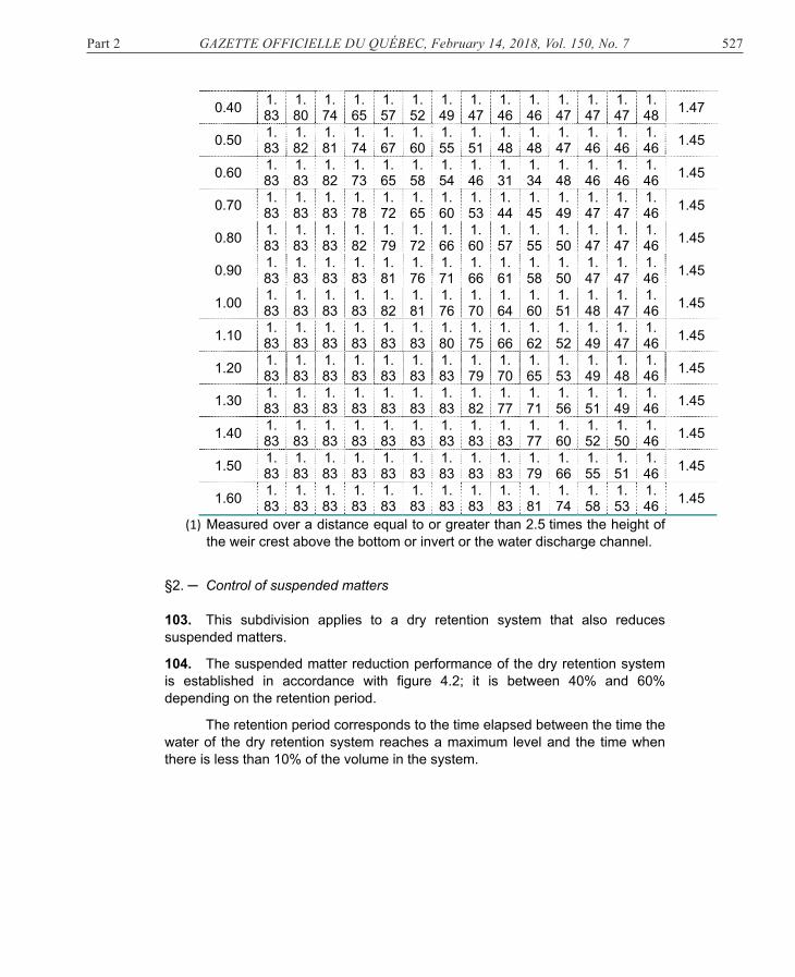
102. The sizing of a flow control device of a non-submerged broad-crested weir type must be established using equation 4-5, in the case of a rectangular weir.
A broad-crested weir is a weir having a thickness allowing the distribution of the pressure to be hydrostatic.
Equation 4-5:
where:
Qsp = Flow discharged by a non- submerged rectangular broad-crested weir (m³/s);
Csp = Flow coefficient for a broad-crested weir determined in accordance with Table 4.1 (m½/s);
L = Length of the weir (m); i = Number of contractions: value = 0, 1 or 2; H = Height of the runoff curve above the crest (m).
Table 4.1 Flow coefficient
Height of the runoff curve above
the crest
(1) (m)
Length of the weir (length in the direction of the water flow)
0.15
0.20
0.30
0.40
0.50
0.60
0.70
0.80
0.90
1.00
1.25
1.50
2.00
3.00 4.00
0.10 1.59
1.56
1.50
1.47
1.45
1.43
1.42
1.41
1.40
1.39
1.37
1.35
1.36
1.40 1.45
0.15 1.65
1.60
1.51
1.48
1.45
1.44
1.44
1.44
1.45
1.45
1.44
1.43
1.44
1.45 1.47
0.20 1.73
1.66
1.54
1.49
1.46
1.44
1.44
1.45
1.47
1.48
1.48
1.49
1.49
1.49 1.48
0.30 1.83
1.77
1.64
1.56
1.50
1.47
1.46
1.46
1.46
1.47
1.47
1.48
1.48
1.48 1.46
Part 2 GAZETTE OFFICIELLE DU QUÉBEC, February 14, 2018, Vol. 150, No. 7 527
0.40 1.83
1.80
1.74
1.65
1.57
1.52
1.49
1.47
1.46
1.46
1.47
1.47
1.47
1.48 1.47
0.50 1.83
1.82
1.81
1.74
1.67
1.60
1.55
1.51
1.48
1.48
1.47
1.46
1.46
1.46 1.45
0.60 1.83
1.83
1.82
1.73
1.65
1.58
1.54
1.46
1.31
1.34
1.48
1.46
1.46
1.46 1.45
0.70 1.83
1.83
1.83
1.78
1.72
1.65
1.60
1.53
1.44
1.45
1.49
1.47
1.47
1.46 1.45
0.80 1.83
1.83
1.83
1.82
1.79
1.72
1.66
1.60
1.57
1.55
1.50
1.47
1.47
1.46 1.45
0.90 1.83
1.83
1.83
1.83
1.81
1.76
1.71
1.66
1.61
1.58
1.50
1.47
1.47
1.46 1.45
1.00 1.83
1.83
1.83
1.83
1.82
1.81
1.76
1.70
1.64
1.60
1.51
1.48
1.47
1.46 1.45
1.10 1.83
1.83
1.83
1.83
1.83
1.83
1.80
1.75
1.66
1.62
1.52
1.49
1.47
1.46 1.45
1.20 1.83
1.83
1.83
1.83
1.83
1.83
1.83
1.79
1.70
1.65
1.53
1.49
1.48
1.46 1.45
1.30 1.83
1.83
1.83
1.83
1.83
1.83
1.83
1.82
1.77
1.71
1.56
1.51
1.49
1.46 1.45
1.40 1.83
1.83
1.83
1.83
1.83
1.83
1.83
1.83
1.83
1.77
1.60
1.52
1.50
1.46 1.45
1.50 1.83
1.83
1.83
1.83
1.83
1.83
1.83
1.83
1.83
1.79
1.66
1.55
1.51
1.46 1.45
1.60 1.83
1.83
1.83
1.83
1.83
1.83
1.83
1.83
1.83
1.81
1.74
1.58
1.53
1.46 1.45
(1) Measured over a distance equal to or greater than 2.5 times the height of the weir crest above the bottom or invert or the water discharge channel.
§2. ─ Control of suspended matters 103. This subdivision applies to a dry retention system that also reduces suspended matters.
104. The suspended matter reduction performance of the dry retention system is established in accordance with figure 4.2; it is between 40% and 60% depending on the retention period.
The retention period corresponds to the time elapsed between the time the water of the dry retention system reaches a maximum level and the time when there is less than 10% of the volume in the system.
528 GAZETTE OFFICIELLE DU QUÉBEC, February 14, 2018, Vol. 150, No. 7 Part 2
Figure 4.2 Suspended matter reduction performance of a dry retention system according to the retention period
[à gauche dans le tableau suivant: Suspended matter reduction performance (%) Bas du tableau: Retention period (h)]
105. The dry retention system must have a flow control device for the reduction of suspended matters that ensures a retention period of the runoff volume to be treated of at least 12 hours.
If a flow control device of the orifice or orifice-plate type is used, the diameter may not be less than 75 mm.
Where a flow control device is added to the dry retention system, the device provided for in subparagraph 1 of the first paragraph of section 96 becomes optional.
106. The maximum flow coming out of the dry retention system for the retention period may not exceed double the average flow determined using equation 4-6.
Part 2 GAZETTE OFFICIELLE DU QUÉBEC, February 14, 2018, Vol. 150, No. 7 529
Equation 4-6: mes = Vquality / [ t ×(3600)]
where:
mes = Average outlet flow of the dry retention system to discharge the runoff volume to be treated (m3/s);
Vquality = Runoff volume to be treated (m3); t = Retention period (h); 3600 = Number of seconds in 1 hour.
107. The sizing of the flow control device for the reduction of suspended matters, in the case of an orifice or orifice plate type, is established using equation 4-7.
Equation-4-7:
where:
A = Flow section of the orifice (m²); mes = Average outlet flow of the dry retention system to
discharge the runoff volume to be treated (m³/s); C = Discharge coefficient of the orifice minimum value: 0.60; 9.81 = Gravitational acceleration (m/s²); H1 = Vertical distance between the centre of the orifice and
the average water level on the discharge of the runoff volume to be treated; the average level corresponds to the average volume divided by the average surface water area (m);
H2 = Vertical distance between the centre of the orifice and the water level downstream of the orifice (m); if the downstream side of the orifice is not submerged and is free-flowing, then H2 = 0.
108. The route followed by the water in the dry retention system by at least 80% of the runoff volume to be treated must have a minimum length/width ratio of 3 to 1, or a minimum ratio of the flow path over the length of the work of 3 to 1.
A flow path is the route followed by the water between an intake in a storm water management work and the outlet of the work.
109. The ratio of the lengths of the shortest flow path and the longest flow path must be at least 0.7, except if less than 20% of the surfaces drained to the dry retention system drain through the shortest flow path.
110. If a flow channel is installed at the bottom of the basin, it must not be made of an impervious material.
530 GAZETTE OFFICIELLE DU QUÉBEC, February 14, 2018, Vol. 150, No. 7 Part 2
111. The reserve volume for the accumulation of sediments provided for in the water and sediment accumulation zone must correspond to at least the smaller of the following values:
(1) 20% of the runoff volume to be treated;
(2) the volume established using equation 4-8.
Equation 4-8: VMES = Msed. × N × Aimp × P/100
where:
VMES = Reserve volume for the accumulation of sediments (m³); Msed. = Volume of sediments produced per year per hectare
(m³/year/ha): minimum value: 0.68; N = Expected number of years of operation without
maintenance (year); minimum value: 5; Aimp = Area of impervious surfaces drained to the dry retention
system (ha); P = Suspended matter reduction performance determined in
accordance with figure figure 4.2 (%). §3. ─ Maintenance program 112. The maintenance program must include
(1) an estimate of the expected reserve volume for the accumulation of sediments in the water and sediment accumulation, the microbasin and, where applicable, the pretreatment work;
(2) the expected number of years of operation without maintenance of the dry retention system, expressed in years, established using equation 4-9.
Equation 4-9: N = VMES / (Msed.× Aimp × P/100)
where:
N = Estimate of the expected number of years of operation without maintenance (year): minimum value: 1;
VMES = Reserve volume for the accumulation of sediments in the dry retention system (m³);
Msed. = Volume of sediments produced per year per hectare (m³/year/ha): minimum value: 0.68;
Aimp = Area of impervious surfaces drained to the dry retention system (ha);
P = Suspended matter reduction performance determined in accordance with figure 4.2 (%);
(3) the need to proceed with the maintenance of the water and
sediment accumulation zone where (a) the accumulation of sediments reaches the mark affixed on the
sediment level indicator;
Part 2 GAZETTE OFFICIELLE DU QUÉBEC, February 14, 2018, Vol. 150, No. 7 531
(b) water remains present 72 hours after the end of the rain event and no other rain event has occurred during that period;
(4) the need to proceed, where applicable, with the maintenance of the pretreatment work where
(a) the accumulation of sediments reaches the mark affixed on the sediment level indicator;
(b) water remains present 24 hours after the end of a rain event and no other rain event has occurred during that period;
(5) the water discharge curve of the retention system according to the water level;
(6) the curve describing the volume of storage according to the water level;
(7) the water level from which the dry retention system overflows at its lowest point. DIVISION II PERMANENT VOLUME RETENTION SYSTEM §1. ─ Flow control
113. The permanent volume retention system must be open.
114. The bottom of the permanent volume retention system must be impervious.
115. The average depth of the volume occupied by permanent water must be greater than 1 m.
The average depth is calculated by dividing the volume occupied by the permanent water by the surface water area occupied by that volume of water.
116. The thickness of the temporary volume of water associated with a 100-year return period must be less than 3 m.
117. A minimum freeboard of 300 mm must separate the water level associated with a 100-year return period and the point at which the permanent volume retention system begins to overflow at its lowest point.
118. The emergency weir must have a capacity allowing the discharge of the flow associated with an event having a 100-year return period.
119. The inlet and outlet pipes must have a minimum inside diameter of 450 mm and a minimum draining slope of 1% over at least 10 m from the permanent volume retention system. If the draining slope is less than 1%, the minimum inside diameter of the pipe must be at least 525 mm.
532 GAZETTE OFFICIELLE DU QUÉBEC, February 14, 2018, Vol. 150, No. 7 Part 2
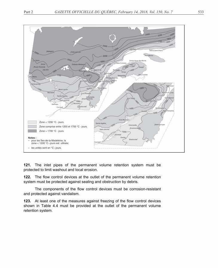
120. The invert of the inlet pipe must be located above the surface of the permanent water or, failing that, at least 150 mm lower than the underside of the ice cover, hg, established using equation 4-10.
Equation 4-10: hg = 20 × (Dg)0.5
where:
hg = Thickness of the ice cover (mm); Dg = Sum of the freezing degree-days at the site of the
permanent volume retention system determined using figure 4.3 or from the climate normals data published by Environment and Climate Change Canada (°C × days).
Figure 4.3 Freezing degree days index
[Texte à l'intérieur de la carte:
Zone < 1,200 °C • days
Zone comprised between 1,200 and 1,700°C • days
Zone > 1,700 °C • days
Notes:
- for the Îles-de-la-Madeleine, zone < 1,200 °C • days is used;
- units are in °C • days]
121. The inlet pipes of the permanent volume retention system must be protected to limit washout and local erosion.
122. The flow control devices at the outlet of the permanent volume retention system must be protected against sealing and obstruction by debris.
The components of the flow control devices must be corrosion-resistant and protected against vandalism.
123. At least one of the measures against freezing of the flow control devices shown in Table 4.4 must be provided at the outlet of the permanent volume retention system.
Part 2 GAZETTE OFFICIELLE DU QUÉBEC, February 14, 2018, Vol. 150, No. 7 533
121. The inlet pipes of the permanent volume retention system must be protected to limit washout and local erosion.
122. The flow control devices at the outlet of the permanent volume retention system must be protected against sealing and obstruction by debris.
The components of the flow control devices must be corrosion-resistant and protected against vandalism.
123. At least one of the measures against freezing of the flow control devices shown in Table 4.4 must be provided at the outlet of the permanent volume retention system.
534 GAZETTE OFFICIELLE DU QUÉBEC, February 14, 2018, Vol. 150, No. 7 Part 2
Table 4.4 Protection at the outlet
[Traduction de la colonne de gauche:
Couvert de glace: Ice cover
Parcours de l'eau: Water route
Conduite d'évacuation: Discharge pipe
Plaque protectrice: Protective plate
Conduite en pente inversée: Invert slope pipe
Diamètre: Diameter
Type of protection Sketch (for information purposes only)
Baffle deflector
Protective plate
Trash rack installed at a shallow angle
Invert slope pipe
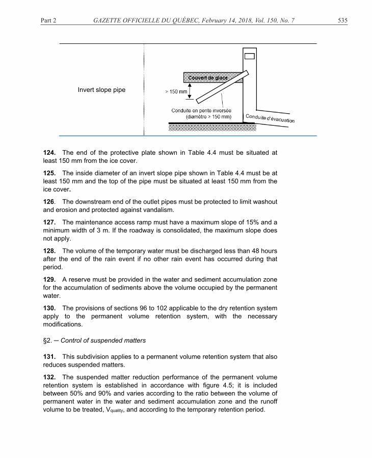
124. The end of the protective plate shown in Table 4.4 must be situated at least 150 mm from the ice cover.
125. The inside diameter of an invert slope pipe shown in Table 4.4 must be at least 150 mm and the top of the pipe must be situated at least 150 mm from the ice cover.
126. The downstream end of the outlet pipes must be protected to limit washout and erosion and protected against vandalism.
127. The maintenance access ramp must have a maximum slope of 15% and a minimum width of 3 m. If the roadway is consolidated, the maximum slope does not apply.
128. The volume of the temporary water must be discharged less than 48 hours after the end of the rain event if no other rain event has occurred during that period.
129. A reserve must be provided in the water and sediment accumulation zone for the accumulation of sediments above the volume occupied by the permanent water.
130. The provisions of sections 96 to 102 applicable to the dry retention system apply to the permanent volume retention system, with the necessary modifications. §2. ─ Control of suspended matters 131. This subdivision applies to a permanent volume retention system that also reduces suspended matters.
132. The suspended matter reduction performance of the permanent volume retention system is established in accordance with figure 4.5; it is included between 50% and 90% and varies according to the ratio between the volume of permanent water in the water and sediment accumulation zone and the runoff volume to be treated, Vquality, and according to the temporary retention period.
Part 2 GAZETTE OFFICIELLE DU QUÉBEC, February 14, 2018, Vol. 150, No. 7 535
Invert slope pipe
124. The end of the protective plate shown in Table 4.4 must be situated at least 150 mm from the ice cover.
125. The inside diameter of an invert slope pipe shown in Table 4.4 must be at least 150 mm and the top of the pipe must be situated at least 150 mm from the ice cover.
126. The downstream end of the outlet pipes must be protected to limit washout and erosion and protected against vandalism.
127. The maintenance access ramp must have a maximum slope of 15% and a minimum width of 3 m. If the roadway is consolidated, the maximum slope does not apply.
128. The volume of the temporary water must be discharged less than 48 hours after the end of the rain event if no other rain event has occurred during that period.
129. A reserve must be provided in the water and sediment accumulation zone for the accumulation of sediments above the volume occupied by the permanent water.
130. The provisions of sections 96 to 102 applicable to the dry retention system apply to the permanent volume retention system, with the necessary modifications. §2. ─ Control of suspended matters 131. This subdivision applies to a permanent volume retention system that also reduces suspended matters.
132. The suspended matter reduction performance of the permanent volume retention system is established in accordance with figure 4.5; it is included between 50% and 90% and varies according to the ratio between the volume of permanent water in the water and sediment accumulation zone and the runoff volume to be treated, Vquality, and according to the temporary retention period.
536 GAZETTE OFFICIELLE DU QUÉBEC, February 14, 2018, Vol. 150, No. 7 Part 2
The temporary retention period corresponds to the time elapsed between the moment the volume of the temporary water reaches a maximum level and the moment there is less than 10% of the volume of maximum temporary water in the system.
The volume of the temporary water is the difference between the volume of water in the permanent volume retention system and the volume of permanent water in the water and sediment accumulation zone.
Figure 4.5 Suspended matter reduction performance
[Traduction de ce qui est dans le tableau suivant:
Suspended matter reduction performance (%)
Temporary retention period:
24 hours
18 hours
24 hours
System with a temporary retention period less than 18 hours
Ratio of permanent pool volume to water quality treatment volume (Vquality)
133. The volume of permanent water in the water and sediment accumulation zone must be at least equal to the runoff volume to be treated.
Part 2 GAZETTE OFFICIELLE DU QUÉBEC, February 14, 2018, Vol. 150, No. 7 537
134. The maximum flow leaving the permanent volume retention system for the temporary retention period may not exceed double the average flow determined using equation 4-11.
Equation 4-11: mes = Vquality / [ t ×(3,600)]
where:
mes = Average flow leaving the permanent volume retention system to discharge the runoff volume to be treated (m3/s);
Vquality = Runoff volume to be treated (m3); t = Temporary retention period (h); 3,600 = Number of seconds in an hour.
135. The sizing of the flow control device for reducing suspended matters, in the case of an orifice or orifice plate type, is established using equation 4-12.
Equation 4-12:
where:
A = Flow section of the orifice (m²); mes = Average flow leaving the permanent volume retention
system to discharge the runoff volume to be treated (m³/s);
C = Discharge coefficient of the orifice: minimum value: 0.60; 9.81 = Gravitational acceleration (m/s²); H1 = Vertical distance between the centre of the orifice and
the average water level during the discharge of the runoff volume to be treated; the average level corresponds to the average volume divided by the average surface water area (m);
H2 = Vertical distance between the centre of the orifice and the water level downstream of the orifice (m); if the downstream side of the orifice is not submerged and is free-flowing, then H2 = 0.
136. The route of the water followed in the permanent volume retention system by at least 80% of the runoff volume to be treated must have a ratio of minimum length/width of 3 to 1, or a minimum ratio of the flow path over the length of the work of 3 to 1.
A flow path is the route followed by the water between an intake in a storm water management work and the outlet of the work. 137. The ratio of the lengths of the shortest flow path and the longest flow path must be at least 0.7, except if less than 20% of the surfaces drained to the permanent volume retention system drain through the shortest flow path.
538 GAZETTE OFFICIELLE DU QUÉBEC, February 14, 2018, Vol. 150, No. 7 Part 2
138. The reserve volume for the accumulation of sediments provided for in the water and sediment accumulation zone must correspond to at least the smaller of the following values:
(1) 20% of the runoff volume to be treated;
(2) the volume established using equation 4-13.
Equation 4-13: VMES = Msed. × N × Aimp × P/100
where:
VMES = Reserve volume for the accumulation of sediments (m³); Msed. = Volume of sediments produced per year per hectare
(m³/year/ha): minimum value: 0.68; N = Expected number of years of operation without
maintenance (year); minimum value: 5; Aimp = Area of impervious surfaces drained to the permanent
volume retention system (ha); P = Suspended matter reduction performance determined in
accordance with figure 4.5 (%).
§3. ─ Maintenance program
139. The maintenance program must include
(1) an estimate of the expected reserve volume for the accumulation of sediments in the water and sediment accumulation zone and, where applicable, in the pretreatment work;
(2) the expected number of years of operation without maintenance of the permanent volume retention system, expressed in years, established using equation 4-14.
Equation 4-14: N = VMES / (Msed.× Aimp × P/100)
where:
N = Estimate of the expected number of years of operation without maintenance (year): minimum value: 1;
VMES = Reserve volume for the accumulation of sediments in the permanent volume retention system (m³);
Msed. = Volume of sediments produced per year per hectare (m³/year/ha): minimum value: 0.68;
Aimp = Area of impervious surfaces drained to the permanent volume retention system (ha);
P = Suspended matter reduction performance determined in accordance with figure 4.5 (%);
(3) the minimum value of the water depth of the volume of permanent
water in the water and sediment accumulation zone to be complied with and the site where the observation must be made;
Part 2 GAZETTE OFFICIELLE DU QUÉBEC, February 14, 2018, Vol. 150, No. 7 539
(4) the need to proceed to the maintenance of the water and sediment accumulation zone where the minimum value of the water depth observed at the site provided for in paragraph 3 is less than the value to be complied with;
(5) the need to proceed, where applicable, to the maintenance of the pretreatment work where the accumulation of sediments reaches the mark affixed on the sediment level indicator;
(6) the water discharge curve of the permanent volume retention system according to the water level;
(7) the curve describing the storage volume according to the water level;
(8) the water level from which the permanent volume retention system overflows at its lowest point. DIVISION III GRASSED DITCH §1. ─ General 140. The width of the water flow into the grassed ditch must be included between 0.5 and 2.5 m.
141. The cross section of the floor of the grassed ditch must be smooth over the width of the ditch.
142. The longitudinal slope of the grassed ditch must be included between 0.3 and 5%.
If the longitudinal slope is greater than 5%, weirs must be installed so that the slope of the water flow between the weirs is between 0.3 and 5%. The weirs must be protected downstream against erosion.
143. The lateral walls of the grassed ditch must have a horizontal distance (H) ratio over a vertical distance (V) of 3H: 1V or be more gentle.
144. The bottom of the grassed ditch must be situated at a minimum distance of 300 mm from the average seasonal maximum groundwater level determined in accordance with section 85.
145. The average speed of water flow, V, established using equation 4-15, in the grassed ditch during the passage of the runoff flow to be treated must be less than 0.5 m/s.
540 GAZETTE OFFICIELLE DU QUÉBEC, February 14, 2018, Vol. 150, No. 7 Part 2
Equation 4-15: � � � �� �� �⁄ �� �⁄
where:
V = Average water flow speed (m/s); N = Roughness coefficient during the passage of the runoff
flow to be treated, Qquality; minimum value of 0.25; R = Hydraulic radius (m); for a trapezoidal channel R is
established using equation 4-16: S = Longitudinal draining slope (m/m);
Equation 4-16: � � ���������
�����√����
where:
y = Water flow level (m); z = Ratio of the horizontal distance over a vertical distance
unit (zH: 1V); value ≥ 3; b = Width at the bottom of the grassed ditch (m); value
between 0.5 and 2.5 m.
146. The water flow level, y, in the grassed ditch during the passage of the runoff flow to be treated must be less than two-thirds the height of mowing of the vegetation, or mature vegetation present in the ditch where no maintenance is carried out, without exceeding 75 mm.
The water flow level, y, is established by iteration using equation 4-17.
Equation 4-17: � � �� � �
where Q = Flow into the ditch (m³/s); A = Area of the flow section, for a trapezoidal channel,
A = by+zy2 (m²); V = Average water flow speed (m/s). 147. The minimum travel time of the water in the ditch, τ, established using equation 4-18, must be equal to or greater than 600 seconds.
1 z
y
b
Part 2 GAZETTE OFFICIELLE DU QUÉBEC, February 14, 2018, Vol. 150, No. 7 541
The minimum travel time of the water is the average time that the water takes to flow into the grassed ditch from the last intake of the grassed ditch to the end of the ditch.
Equation 4-18:
where:
τ = Minimum travel time of the water; L = Length of the grassed ditch, from the last water intake to
the end of the ditch (m); V = Average water flow speed (m/s).
148. The suspended matter reduction performance is established using equation 4-19 if water input to the grassed ditch is evenly distributed over the length of the ditch.
Equation 4-19:
where:
P = Suspended matter reduction performance (%); V = Average water flow speed (m/s); L = Length of the grassed ditch (m).
Where the length of the ditch, L, is less than the product of the average water flow speed, V, multiplied by 600 seconds, V x 600, the suspended matter reduction performance, P, is 0%.
149. Each square metre of the surface of the grassed ditch must be covered 90% by shoots at least 120 mm high after a 7-week or more growth within the growth periods indicated in Table 4.6, according to the hardiness zone determined by Natural Resources Canada.
Table 4.6 Growth period according to hardiness zone
Hardiness zone Growth period 2a and 2b From 30 June to 21 August 3a and 3b From 15 June to 30 August 4a and 4b From 21 May to 10 September 5a and 5b From 10 May to 21 September
150. The average water flow speed, V, during the passage of the flow having a 5-year return period must not exceed the values indicated in Table 4.7 according to the type of vegetation in place, the draining slope and the nature of the soils.
542 GAZETTE OFFICIELLE DU QUÉBEC, February 14, 2018, Vol. 150, No. 7 Part 2
Table 4.7 Average water flow speed
Type of vegetation in the
ditch Slope
(%)
Speed (m/s)
Erosion-resistant soil
Non-erosion-resistant soil
Well-rooted grass 0-5 5-10 > 10
2.44 2.13 1.83
1.83 1.52 1.22
Short-blade grass 0-5 5-10 > 10
2.13 1.83 1.52
1.52 1.22 0.91
Mixture 0-5 5-10
1.52 1.22
1.22 0.91
Grasses 0-5 1.07 0.76 §2. ─ Maintenance program
151. The maintenance program must include the following information:
(1) plants must be kept at a size of at least 120 mm;
(2) each square metre of the surface of the grassed ditch must be reseeded where less tha 90% of shoots are less than 120 mm high after a 7-week or more growth period within the growth periods indicated in Table 4.6;
(3) the ditch must be subject to maintenance where water is present in the grassed ditch more than 48 hours after the end of the rain event and no other rain event has occurred during that period. DIVISION IV HYDRODYNAMIC SEPARATOR §1. ─ General 152. To be installed, a hydrodynamic separator must comply with the following:
(1) have been verified under Canada's Environmental Technology Verification Program or as part of a verification process compliant with ISO Standard 14034 Environmental management — Environmental technology verification (ETV);
(2) the verification conducted under paragraph 1 confirms, through a verification certificate or declaration, that the laboratory test procedure for oil and grit separators published by Canada’s Environmental Technology Verification Program has been complied with;
Part 2 GAZETTE OFFICIELLE DU QUÉBEC, February 14, 2018, Vol. 150, No. 7 543
(3) the verification certificate or declaration referred to in paragraph 2 is not expired on the date on which the plans and specifications are signed or is dated not more than 3 years before the signing of the plans and specifications;
(4) the conditions and restrictions provided for in the verification certificate or declaration, the technology sheet and the verification report produced at the end of the verification process performed under paragraph 1 are complied with.
153. For a given loading rate, a hydrodynamic separator may be installed in a series configuration if a test for resuspension of sediments conducted at a loading rate corresponding to at least 200% of the loading rate has been successful.
An installation in a series configuration is an installation in which flows travelling in a storm water management system are sent to a non-bypass treatment unit upstream of the hydrodynamic separator.
154. For a given loading rate, a hydrodynamic separator may be installed in a parallel configuration if a test for resuspension of sediments conducted at a loading rate corresponding to at least 125% of the given loading rate has been successful.
An installation in a parallel configuration is an installation in which flows equal to or less than the treatment capacity of the hydrodynamic separator are sent, the excess flows being bypassed upstream by an outside work to bypass the hydrodynamic separator in order to reach the storm water management system downstream of the hydrodynamic separator.
155. A test for resuspension is successful where the concentration of suspended matters at the effluent is less than 20 mg/L for a series configuration and 10 mg/L for a parallel configuration, after correction to take into account the concentration of raw water and the smallest particle that may be intercepted during the suspended matter reduction performance.
For the purposes of the correction provided for in the first paragraph,
(1) a 5 µm particle size must be postulated in raw water if no granulometric analysis of the suspended matters contained in the raw water has been conducted;
(2) the size of the smallest particle that may be intercepted for a given loading rate corresponds to D5 of the granulometric curve of particles found in the tank following suspended matter removal tests conducted at 25% of the given loading rate; D5 is the diameter corresponding to the point on the granulometric curve where the percentage of passing particles is 5%; linear interpolation is allowed to obtain D5.
156. A hydrodynamic separator may not be used at a given loading rate if no sediment resuspension test has been conducted at a loading rate corresponding to at least 125% of the given loading rate.
544 GAZETTE OFFICIELLE DU QUÉBEC, February 14, 2018, Vol. 150, No. 7 Part 2 §2. ─ Suspended matter reduction performance
157. Hydrodynamic separators may not be installed in series to increase the suspended matter reduction performance.
158. The annual suspended matter reduction performance for a given flow is established
(1) by multiplying the suspended matter reduction performance associated with the loading rates corresponding to 25%, 50%, 75%, 100% and 125% of the given loading rate by the weighting factors indicated in Table 4.8; and
(2) by adding the products obtained in subparagraph 1.
For the purpose of establishing the suspended matter reduction performance provided for in the first paragraph,
(1) the suspended matter reduction performance values must come from experimental results at the end of the verification process performed under paragraph 1 of section 152, without extrapolation of the results;
(2) the suspended matter reduction performance must be 0% for loading rates greater than those tested; and
(3) the suspended matter reduction performance for loading rates less than those tested must be capped to the performance measured for the smallest loading rate tested.
159. A suspended matter reduction performance curve must be drawn. The curve must link the performances determined in section 158 and the loading rate. For that purpose, the loading rates tested during the performance tests must at least constitute the points on the curve.
160. The floor of the hydrodynamic separator tank installed must have an area greater than or equal to the area established using equation 4-20 for the annual suspended matter reduction performance sought.
Part 2 GAZETTE OFFICIELLE DU QUÉBEC, February 14, 2018, Vol. 150, No. 7 545
Equation 4-20: A = Qquality/q
where:
A = Area of the floor of the hydrodynamic separator tank (m²);
Qquality = Value of the runoff flow to be treated (m³/s); q = Loading rate corresponding to the performance
sought determined from the performance curve plotted under section 159 (m³/s/m²).
161. The inside sizes of length and width of the hydrodynamic separator tank must be geometrically proportional to those of the hydrodynamic separator tested.
The height and depth sizes of the hydrodynamic separator must be proportional to those of the hydrodynamic separator tested in a proportion of at least 85%.
§3. ─ Maintenance program
162. The maintenance program must include
(1) the manufacturer’s maintenance plan for the hydrodynamic separator;
(2) the indication that maintenance is required where the accumulated sediments exceed the maintenance threshold; the maintenance threshold is the sediment level for which the distance between the water surface and the top of the accumulated sediments in the separator tank is less than 85% of the distance between the surface of the water and the preloading level of the sediments present in the hydrodynamic separator tank tested during the performance tests, after the scaling of the distance proportionally to the diameters of the separator installed and tested;
(3) an indicator of the expected number of years of operation without maintenance of the hydrodynamic separator, expressed in years, established using equation 4-21.
Equation 4-21: N = VMES / (Msed.× Aimp × P/100)
where:
N = Expected number of years of operation without maintenance (year);
546 GAZETTE OFFICIELLE DU QUÉBEC, February 14, 2018, Vol. 150, No. 7 Part 2
VMES = Volume available in the tank for the accumulation of sediments situated below the maintenance threshold (m³);
Msed. = Volume of sediments produced per year per hectare (m³/year/ha): minimum value: 0.68;
Aimp = Area of the impervious surfaces drained to the hydrodynamic separator (ha);
P = Suspended matter reduction performance associated with the loading rate determined from the performance curve plotted under section 159 (%).
DIVISION V COMMERCIAL STORM WATER TREATMENT TECHNOLOGY §1. ─ General 163. To be installed, a commercial storm water treatment technology must meet the conditions provided for in one of the following paragraphs:
(1) the commercial storm water treatment technology is approved by the Washington State Department of Ecology for a General Use Level Designation (GULD) and complies with the conditions and restrictions issued for that commercial storm water treatment technology by the Washington State Department of Ecology for a General Use Level Designation (GULD);
(2) the commercial storm water treatment technology must be verified as part of a verification process compliant with ISO Standard 14034 Environmental management -- Environmental technology verification (ETV) and the verification declaration of that technology attests that the Technology Assessment Protocol – Ecology (TAPE), produced by the Washington State Department of Ecology, has been complied with. That verification declaration may not be expired on the date on which the plans and specifications were signed or must be dated not more than 3 years preceding the date of signing of the plans and specifications. The conditions and restrictions provided for in the verification declaration and the verification report produced at the end of the verification process must be complied with;
(3) the commercial storm water treatment technology has been verified as part of a verification process compliant with ISO Standard 14034 and the verification declaration of that technology attests that the TARP Tier II Protocol, including the amendments published in 2006 and 2009 by the New Jersey Department of Environmental Protection, has been complied with. That verification declaration may not be expired on the date on which the plans and specifications were signed or must be dated not more than 3 years preceding the date of signing of the plans and specifications. The conditions and restrictions provided for in the verification declaration and the verification report produced at the end of the verification process must be complied with.
Part 2 GAZETTE OFFICIELLE DU QUÉBEC, February 14, 2018, Vol. 150, No. 7 547
164. The suspended matter reduction performance for a commercial storm water treatment technology corresponds
(1) to the Treatment type recognized by the Washington State Department of Ecology for a commercial storm water treatment technology referred to in paragraph 1 of section 163;
(2) to 80% of suspended matter reduction, if the average suspended matter reduction performance based on the measurement of the concentration of suspended matters, SSC, indicated in the verification report, is equal to or greater than 80% according to the results reported in the verification report for a commercial storm water treatment technology that meets the conditions referred to in paragraph 2 or paragraph 3 of section 163.
165. Commercial storm water treatment technologies may not be installed in series to increase the suspended matter reduction performance. §2. ─ Maintenance program
166. The maintenance program must include the maintenance plan of the manufacturer of the commercial storm water treatment technology. CHAPTER V FINAL 167. This Regulation comes into force on the fifteenth day following its publication in the Gazette officielle du Québec.
548 GAZETTE OFFICIELLE DU QUÉBEC, February 14, 2018, Vol. 150, No. 7 Part 2
SCHEDULE I PLANT SPECIES PROHIBITED IN THE DESIGN OF A PROJECT (s. 51)