4FT. x 8FT. FOLDING TRAILER OWNER’S MANUAL WARNING: Read carefully and understand all INSTRUCTIONS before operating. Failure to follow the safety rules and other basic safety precautions may result in serious personal injury. Item #37561
Transcript
4FT. x 8FT. FOLDING TRAILER
OWNER’S MANUAL
WARNING:
Read carefully and understand all INSTRUCTIONS before operating. Failure to follow the safety rules and other basic safety precautions may result in serious personal injury.
Item #37561
2
Thank you very much for choosing an Ironton Product! For future reference, please complete the owner’s record below: Model: _______________ Purchase Date: _______________ Save the receipt, warranty and these instructions. It is important that you read the entire manual to become familiar with this product before you begin using it. This trailer is designed for certain applications only. The distributor cannot be responsible for issues arising from modification. We strongly recommend this trailer is not modified and/or used for any application other than that for which it was designed. If you have any questions relative to a particular application, DO NOT use the trailer until you have first contacted the distributor to determine if it can or should be performed on the product. For technical questions please call 1-800-222-5381.
TECHNICAL SPECIFICATIONS
GENERAL SAFETY RULES
WARNING: Read and understand all instructions. Failure to follow all instructions listed below
may result in electric shock, fire and/or serious injury.
WARNING: The warnings, cautions, and instructions discussed in this instruction manual cannot cover all possible conditions or situations that could occur. It must be understood by the operator that common sense and caution are factors that cannot be built into this product, but must be supplied by the operator.
• Keep the work area clean and dry. Damp or wet work areas can result in injury.
• Keep children away from work area. Do not allow children to handle this product.
• Always wear ANSI-approved safety glasses and heavy-duty work gloves during assembly and use. Do not wear loose clothing or jewelry which can get caught in moving parts.
ITEM DESCRIPTION
Tires 4.80-12 Tubeless
Wheel 4 Bolt Demountable
Bed Dimensions 4 Ft. x 8 Ft.
Ball/Coupler Size 1-7/8 Inch
Coupler Capacity Class I; 2000 Lbs. Maximum Gross Load
Load Capacity 1170 Lbs.
GAWR 1400 Lbs. with 4.80-12 Tires at 60 PSI Cold
GVWR 1400 Lbs.
3
• Store idle equipment. When not in use, tools and equipment should be stored in a dry location to inhibit rust. Always lock up tools and equipment, and keep out of reach of children.
• Use the right tool for the job. Do not attempt to force small equipment to do the work of larger industrial equipment. There are certain applications for which this equipment was designed. It will do the job better and more safely at the capacity for which it was intended. Do not modify this equipment, and do not use this equipment for a purpose for which it was not intended.
• Check for damaged parts. Before using this product, carefully check that it will operate properly and perform its intended function. Check for damaged parts and any other conditions that may affect the operation of this product. Replace damaged or worn parts immediately.
• Do not overreach. Keep proper footing and balance at all times to prevent tripping, falling, back injury, etc.
• DO NOT use this trailer when tired or distracted.
• Industrial applications must follow OSHA requirements.
SPECIFIC OPERATION WARNINGS
• Before each use, always examine the trailer for proper tire (19) condition and air pressure, damaged Tail Lights (28L, 28R), damaged Side Running Lights (24), loose bolts and nuts, structural cracks, bends and any other condition that may affect its safe operation. Do not use the Trailer even if minor damage appears.
• Before each use, always attach the Safety Chains (8) of the trailer to the towing vehicle. Make sure the Safety Chains are attached to the towing vehicle with the equal length at each side. Do not allow the Safety Chains to drag on the ground.
• Always check to make sure the payload being transported is properly and safely secured in the trailer. Load the Trailer evenly from side to side with 60% of the load forward of the Axle (16).
• Make sure the towing vehicle is capable of towing this trailer and its payload. Make sure the hitch on the towing vehicle is capable of towing the Trailer and its payload. The towing capacity of the hitch is typically stamped on the hitch drawbar.
• Make sure the hitch coupler (7) and the vehicle’s Ball Hitch (not included) are of equal mating size (1-7/8”) and are rated equal to or greater than the weight of the trailer and its payload.
• Do not exceed 45 miles per hour when towing the trailer. Excess speed is a major cause of vehicle-trailer accidents.
• The Tail Light Bulbs supplied with this trailer are for a 12 VOLT DC electrical system only. Do not attempt to power the Light Bulbs with any other type or voltage electrical current.
• Whenever possible, park the trailers on a flat, level, paved surface and chock both tires to keep the trailer from accidently moving.
• Before attempting to fold up the trailer, make sure it is on a flat, level, solid surface and chock both Tires (19).
• Never attempt to fold up the trailer without the help of one or two able assistants.
• DO NOT exceed the 1170 pound weight capacity.
• DO NOT allow anyone to ride in the towed vehicle or on the trailer.
• DO NOT transport passengers or heavy cargo inside the vehicle that is being towed.
• The coupler must be properly secured to the hitch ball. After assembly and attachment, pull up and down on the hitch coupler to make sure the hitch ball is snug in the hitch coupler. If the coupler is not secured properly, it could come loose while the trailer is in motion, causing property damage, serious personal injury or even death.
• Make wide turns when towing a loaded trailer, avoiding both sharp turns and U-turns. Turning too sharply can cause damage to the trailer and/or the tow vehicle.
4
UNPACKING
When unpacking, check to make sure all the parts shown on the Parts List are included. If any parts are missing or broken, please call the distributor at 1-800-222-5381
ASSEMBLY INSTRUCTIONS
Read the following instructions step-by-step for easy assembly according to the complete parts and hardware list. Average assembly time is 3 hours. You will need the following tools to assemble your trailer. 16mm Wrench or Socket 17mm Wrench or Socket 18mm Wrench or Socket 19mm Wrench or Socket 20mm Wrench or Socket 21mm Wrench or Socket Drill (For Plywood Installation) Pliers Phillips Screw Driver 3/8" Drill Bit (For Side Rail Installation)
NOTE:
The trailer parts are called out by standing at the rear of the trailer looking toward the hitch. The trailer frame parts are labeled. Do not tighten any nuts and bolts until the entire trailer is assembled. Installing the plywood deck, which you must supply, is the last step after tightening all the nuts and bolts. Periodically check all the nuts and bolts for tightness. Tighten the wheel lug nuts to 85-90 ft-lbs. of torque after assembling the trailer, after the first 20, 50 and 100 miles of driving and before each tow thereafter.
STEP 1
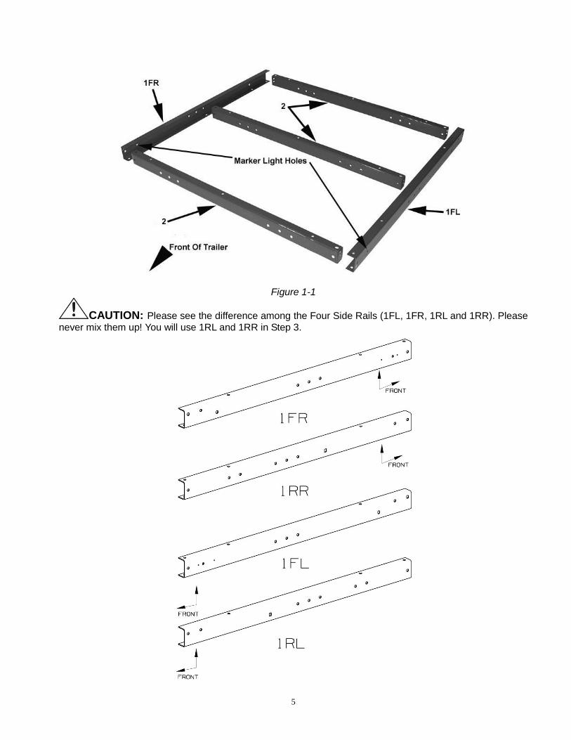
1. Lay out the front side rails (1FL and 1 FR), cross members (2) as shown. Note the location of the marker light holes in the front side rails (1FL and 1 FR). See figure 1-1.
5
Figure 1-1
CAUTION: Please see the difference among the Four Side Rails (1FL, 1FR, 1RL and 1RR). Please never mix them up! You will use 1RL and 1RR in Step 3.
6
2. Connect front cross member (2) to left frame rail (1FL) with M10 x 20 bolt (D) and M10 nylon lock nut (G). See figure1-2.
Figure 1-2 3. Position stake pocket (25) and connect the center cross member (2) to left frame rail (1FL) with M10 x 20 bolt (D), M10 x 30 bolt (C) and M10 nylon lock nuts (G). The center cross member goes in the rear of the three holes on left frame rail. See figure 1-3.
Figure 1-3 4. Verify that the rear cross member (2) is positioned with the opening the channel facing the hitch. See figure1-4. 5. Position rotation bracket (25) as shown and connect rear cross member (2) to left frame rail (1FL) with M10 x 20 bolt (D), M10 x 30 bolt (C) and M10 nylon lock nuts (G). See figure 1-4.
7
Figure 1-4 6. Connect right frame rail (1FR) to the three cross members (2) using steps 2-5 above.
STEP 2
1. Turn assembled frame over. 2. Install M10 x 20 bolts (D) and M10 nylon lock nuts (G) to connect the side frame rails to front cross member. 3. Position left connecting rail (3L) and right connecting rail (3R) on trailer frame as shown. 4. Connect left and right connecting rails to front cross member with M10 x 20 bolts (D) and M10 nylon lock nuts (G). 5. At the rear of the connecting rails, install M10 x 30 bolts (C) down through connecting rails, side frame rails and center cross member. Install M10 nylon locknuts (G) on bolts. See figure 2-1 .
Figure 2-1
8
6. Position left tow bar bracket (4L) and right tow bar bracket (4R) on cross members (2) and connect with M10 x 20 bolt (D) and M10 nylon locknuts (G). See figure 2-2.
Figure 2-2
7. Install tow bar (4) with the opening facing up as shown between tow bar brackets. See figure 2-3. 8. Install tow bar pin (9) and lock pin (M). 9. Install M12 x 90 bolt (P) and M12 nylon lock nut (O). 10. Turn assembled frame over.
Figure 2-3 11. Install “T” plate (5) onto tow bar and install wing nut (N). Connect “T” plate (5) to connecting rails (3L) and
(3R) with M10 x 20 bolts (D) and M10 nylon lock nuts (G). See figure 2-4.
9
Figure 2-4
STEP 3
1. Lay out the rear side rails (1RL and 1RR) and three cross members (2) as shown. See figure 3-1.
Figure 3-1
10
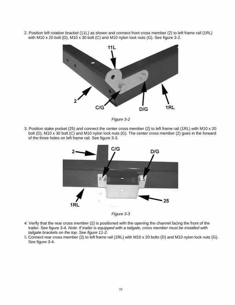
2. Position left rotation bracket (11L) as shown and connect front cross member (2) to left frame rail (1RL)
with M10 x 20 bolt (D), M10 x 30 bolt (C) and M10 nylon lock nuts (G). See figure 3-2.
Figure 3-2
3. Position stake pocket (25) and connect the center cross member (2) to left frame rail (1RL) with M10 x 20
bolt (D), M10 x 30 bolt (C) and M10 nylon lock nuts (G). The center cross member (2) goes in the forward of the three holes on left frame rail. See figure 3-3.
Figure 3-3 4. Verify that the rear cross member (2) is positioned with the opening the channel facing the front of the
trailer. See figure 3-4. Note: If trailer is equipped with a tailgate, cross member must be installed with tailgate brackets on the top. See figure 11-2.
5. Connect rear cross member (2) to left frame rail (1RL) with M10 x 20 bolts (D) and M10 nylon lock nuts (G). See figure 3-4.
11
Figure 3-4
6. Connect right frame rail (1RR) to the three cross members (2) using steps 2-5 above. 7. Connect front and rear frame rotational brackets together with M10 x 20 bolts (D) and M10 nylon lock nuts
(G). See figure 3-5.
Figure 3-5 8. Fold rear frame over onto front frame. 9. Install four M10 x 20 bolts (D) and M10 nylon lock nuts (G) as shown through the rear frame rails and cross members. See figure 3-6.
12
Figure 3-6
10. Unfold trailer, and then fold front frame onto rear frame. The tow bar will now be on top.
STEP 4
1. Install left spring hanger (12L) and right spring hanger (12R) to rear frame rails with M10 x 30 bolts (C), M10 x 20 bolts (D) and M10 nylon lock nuts (G) as shown. See figure 4-1.
Figure 4-1 2. Connect left caster base (30L) and right caster base (30R) to left (12L) and right (12R) spring hangers with M10 x 20 bolts (D) and M10 nylon lock nuts (G). See figure 4-2.
Right Rear Side Figure 4-2 Left Rear Side
13
STEP 5
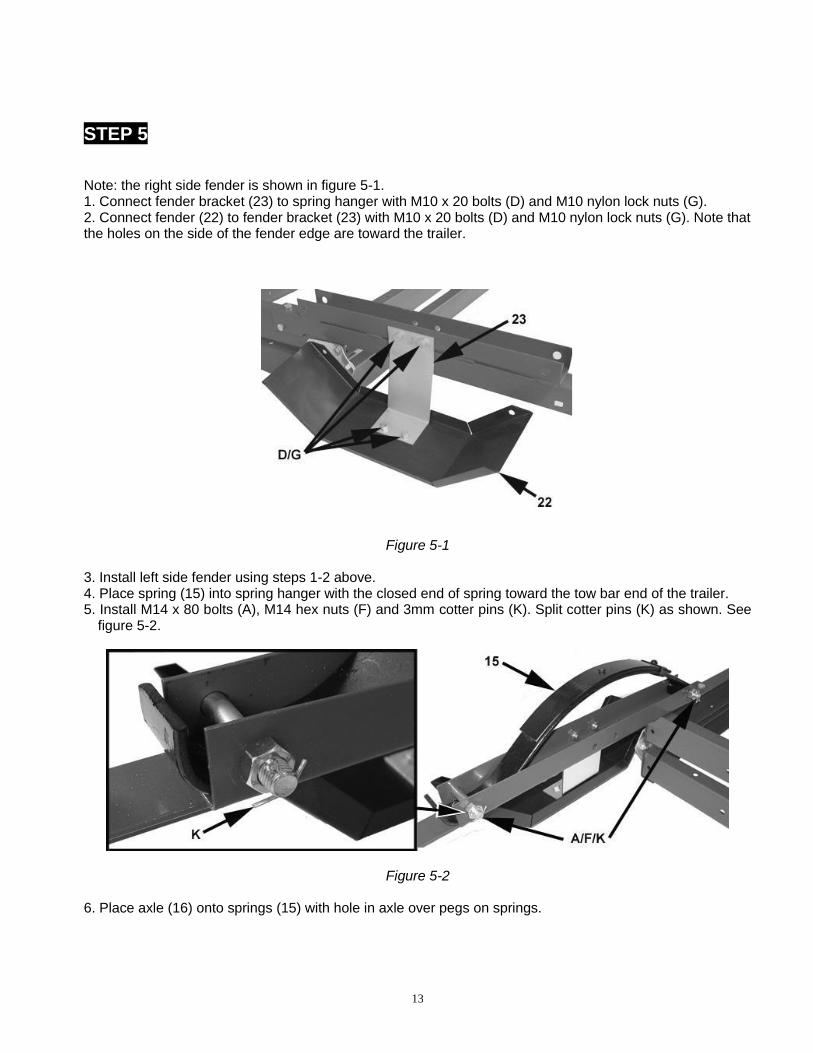
Note: the right side fender is shown in figure 5-1. 1. Connect fender bracket (23) to spring hanger with M10 x 20 bolts (D) and M10 nylon lock nuts (G). 2. Connect fender (22) to fender bracket (23) with M10 x 20 bolts (D) and M10 nylon lock nuts (G). Note that the holes on the side of the fender edge are toward the trailer.
Figure 5-1 3. Install left side fender using steps 1-2 above. 4. Place spring (15) into spring hanger with the closed end of spring toward the tow bar end of the trailer. 5. Install M14 x 80 bolts (A), M14 hex nuts (F) and 3mm cotter pins (K). Split cotter pins (K) as shown. See
figure 5-2.
Figure 5-2 6. Place axle (16) onto springs (15) with hole in axle over pegs on springs.
14
Figure 5-3 7. Fasten axle to springs with two U-bolts (17), spring plate (14) four M10 nylon lock nuts (G). 8. Repeat step 7 for other side of trailer.
Figure 5-4
STEP 6
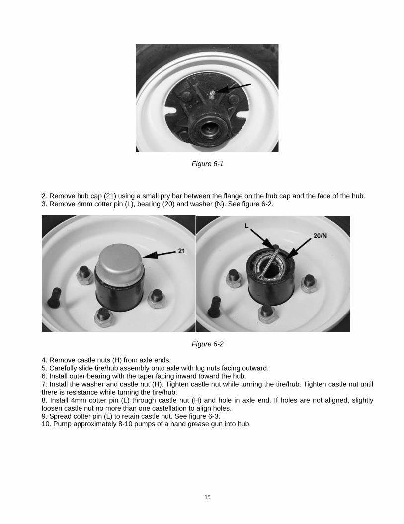
1. Locate both tire/hub assemblies. For easy access, be certain that grease fittings are facing out away from the hub as shown in figure 6-1.
15
Figure 6-1 2. Remove hub cap (21) using a small pry bar between the flange on the hub cap and the face of the hub. 3. Remove 4mm cotter pin (L), bearing (20) and washer (N). See figure 6-2.
Figure 6-2 4. Remove castle nuts (H) from axle ends. 5. Carefully slide tire/hub assembly onto axle with lug nuts facing outward. 6. Install outer bearing with the taper facing inward toward the hub. 7. Install the washer and castle nut (H). Tighten castle nut while turning the tire/hub. Tighten castle nut until there is resistance while turning the tire/hub. 8. Install 4mm cotter pin (L) through castle nut (H) and hole in axle end. If holes are not aligned, slightly loosen castle nut no more than one castellation to align holes. 9. Spread cotter pin (L) to retain castle nut. See figure 6-3. 10. Pump approximately 8-10 pumps of a hand grease gun into hub.
16
Figure 6-3 11. Install hub cap (21) firmly on hub with rubber mallet. See figure 6-4.
Figure 6-4 12. Repeat steps 2-10 for the other tire/hub. 13. Unfold trailer. Trailer will now be setting on the tires. 14. Even though the wheels are mounted to the hubs, you must tighten all the lug nuts (I) to 85-90 lb/ft of torque.
STEP 7
1. Install coupler (7) to tow bar with M10 x 90 bolts (B) and M10 nylon lock nuts. The rear M10 x 90 bolt (B) goes through center link of safety chain (8).
17
Figure 7-1
WARNING:
Risk of trailer uncoupling. The coupler provided with your trailer requires a 1-7/8 inch hitch ball. Use only a 1-7/8 inch hitch ball on the tow vehicle towing this trailer. NOTE: To reduce friction between the ball hitch and coupler, apply a layer of multipurpose lithium grease
over ball hitch. Wipe off excess grease when not in use to avoid staining clothes.
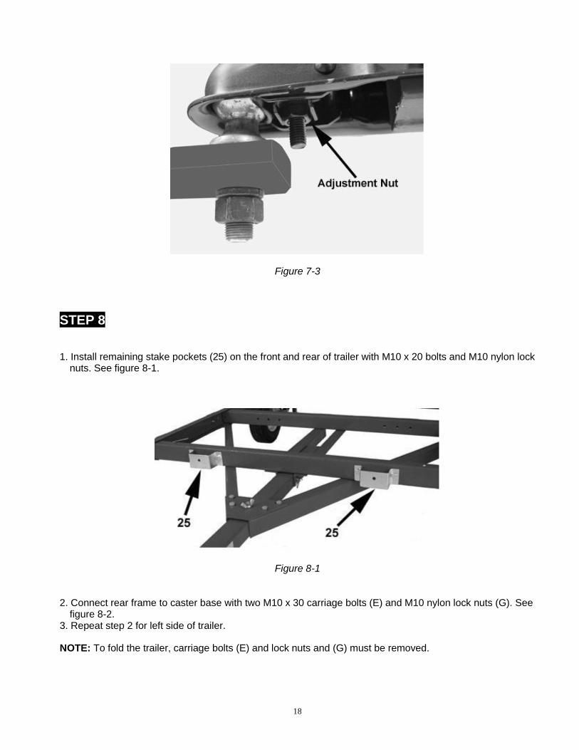
Figure 7-2 Pull up and down on the coupler to see if the coupler is fitting snug on the ball. There must not be play between the ball and coupler. If there is play, tighten the adjustment nut until no play is present. If the nut is too tight, the handle will not lock. See figure 7-3.
18
Figure 7-3
STEP 8
1. Install remaining stake pockets (25) on the front and rear of trailer with M10 x 20 bolts and M10 nylon lock nuts. See figure 8-1.
Figure 8-1 2. Connect rear frame to caster base with two M10 x 30 carriage bolts (E) and M10 nylon lock nuts (G). See
figure 8-2. 3. Repeat step 2 for left side of trailer.
NOTE: To fold the trailer, carriage bolts (E) and lock nuts and (G) must be removed.
19
Figure 8-2 4. Check alignment and securely tighten all hardware. 5. Verify that you have tightened wheel lug nuts to 85-90 lb/ft of torque.
STEP 9
1. Install left and right tail light brackets (26) with M10 x 20 bolts (D) and M10 nylon lock nuts (G). 2. Install license plate bracket (27) and left tail light (with clear lens on bottom) on left side bracket. See figure 9-1. 3. Install right side tail light.
Figure 9-1 4. Insert light wire through small hole in frame rail and install side marker lights (24) to front corner of frame
rails with M4 self tapping screws. There is one light on each side of the trailer. See figure 9-2.
20
Figure 9-2
5. Unroll the wiring harness. 6. Position harness so that the harness connector is approximately 18 inches beyond the coupler. 7. Route the harness through the tow bar. See figure 9-3. 8. Route the green/brown wires down the right side frame rail. See figure 9-3. 9. Route the yellow/brown wires down the left side frame rail. See figure 9-3. 10. Be sure to leave 4 inches of excess wire at the end of the tow bar and 16 inches of excess at the fold points.
Figure 9-3
11. Attach the white ground wire to the small hole on the left side of tow bar with a 4mm self-tapping screw
(J). See figure 9-4.
21
Figure 9-4 12. Connect front corner running lights to the brown harness wires with plastic wire connectors. Use pliers to
squeeze connectors closed. See figure 9-5.
Figure 9-5
13. Use push on wire clips to fasten wires to the lower flange of the rails and cross members of the trailer.
Verify that there is adequate harness to fold the trailer and tow bar. 14. Cut the yellow/brown and green/brown wires to the appropriate lengths and strip wire ends back ¾ inch. 15. On the right side of the trailer, connect the green wires together and the brown wires together with wire
nuts. See figure 9-6. 16. On the left side of the trailer, connect the yellow wires together and the brown wires together with wire
nuts. See figure 9-6.
Right Side Figure 9-6 Left Side
STEP 10
The 3/4 inch plywood and hardware for the trailer floor are not included with your trailer. This step indicates the drilling locations for the hardware. Drill all holes with a high speed drill bit. Use 3/8in. flat washers, lock washers and hex nuts to mount floor tight to trailer frame. See figure 10-1.
22
Figure 10-1
23
SAFE USE AND OPERATION RULES
1. TOWING VEHICLE
• Make sure vehicle is capable of towing the load.
• Excess speed is the second most important cause of car-trailer accidents. Recommended maximum speed for all passenger cars towing trailers is 45 mph.
2. HITCH, BALL, COUPLER
• Check that the hitch on the towing vehicle is capable of towing the trailer. The capability of the hitch is normally stamped on the hitch bar and the capacity of the ball is stamped on the ball.
• Make sure the coupler and the ball the same size and are rated equal to or greater than the load.
• Never attach anything other than the proper size coupler to the ball for towing.
3. SAFETY CHAINS
• Always cross the chains under the coupler and connect the safety chains to the tow vehicle frame.
• Check that safety chains are attached to towing vehicle with the same length for each side.
• Do not allow chains to drag on ground.
4. LOADING
• Never overload trailer. Maximum load is 956 pounds.
• Load trailer evenly from side to side with 60% of the load forward of the axle. It is important that the tongue be pressing down on the hitch, but not exceeding a downward force of 90 pounds.
• Reduce weight in car trunk and rear seat areas by amount of tongue weight of your trailer.
• It is unsafe and also against the law to carry passengers on or in any trailer.
• Always lock tail gate in the travel position before towing trailer.
24
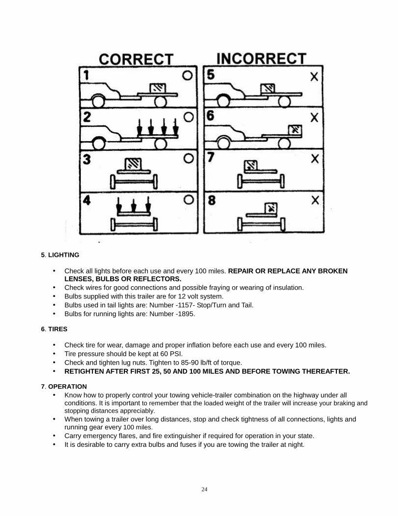
5. LIGHTING
• Check all lights before each use and every 100 miles. REPAIR OR REPLACE ANY BROKEN LENSES, BULBS OR REFLECTORS.
• Check wires for good connections and possible fraying or wearing of insulation.
• Bulbs supplied with this trailer are for 12 volt system.
• Bulbs used in tail lights are: Number -1157- Stop/Turn and Tail.
• Bulbs for running lights are: Number -1895.
6. TIRES
• Check tire for wear, damage and proper inflation before each use and every 100 miles.
• Tire pressure should be kept at 60 PSI.
• Check and tighten lug nuts. Tighten to 85-90 lb/ft of torque.
• RETIGHTEN AFTER FIRST 25, 50 AND 100 MILES AND BEFORE TOWING THEREAFTER. 7. OPERATION
• Know how to properly control your towing vehicle-trailer combination on the highway under all conditions. It is important to remember that the loaded weight of the trailer will increase your braking and stopping distances appreciably.
• When towing a trailer over long distances, stop and check tightness of all connections, lights and running gear every 100 miles.
• Carry emergency flares, and fire extinguisher if required for operation in your state.
• It is desirable to carry extra bulbs and fuses if you are towing the trailer at night.
25
8. MAINTENANCE
• Check and maintain the trailer, coupler, ball and hitch before each use and every 200 miles.
• Inspect coupler, hitch and ball for damage before each use.
• Ball or hitch can be damaged in parking, hitting curbs, dragging when crossing ditches or railroad tracks.
• Check safety chains and hooks for wear and do not allow safety chains to drag on ground.
• To prevent bearing damage, disassemble and repack wheel bearing with a good grade of wheel bearing grease every 2000-3000 miles or yearly.
• If you do not know how to repack wheel bearing, take your trailer to a qualified technician. IMPORTANT: The purpose of the following notices is to give you tips on safe use and operation of your utility trailer. 1. Please read the instructions carefully and follow them step-by-step for easy assembly. Please keep this
instruction. 2. Please double check the assembling step-by-step to be sure each is followed. 3. Before using, please inspect your trailer. 4. Do not remove the VIN sticker from the tow bar. NOTICE:
• Re-pack wheel bearings after every 3000 miles of use.
• Keep tire pressure at 60 PSI with tires at ambient temperature.
• Please insure you comply with the following before using your trailer.
1) Tighten U-bolts 2) Tighten wheel lug nuts. 3) Coupler is secured to the ball and is properly adjusted. 4) Cross and connect safety chains. 5) Trailer load must not exceed its 1000 lbs capacity and must be properly secured. 6) Trailer load size must not exceed trailers bed board size. TRAILER LICENSING NOTICE: Some states may consider that this trailer kit is and specially constructed or a homemade vehicle for registration, licensing and/or titling purposes. The M.C.O. (Manufacturer’s Certificate of Origin) supplied with your trailer must be filled out and signed by the dealer transferring ownership to you. When licensing your trailer, you will need the signed M.C.O., a purchase invoice, cash register receipt, or bill of sale showing the purchase and retail sales tax or use tax collection by the retailer. Take these to your local Department of Motor Vehicles and upon payment of the appropriate State fees, you will be issued a title, registration and license plate (if required). Some states will require inspection of the assembled and finished trailer kit before issuing a title registration/license. If you require additional information or guidance on licensing or titling, please consult your State Department of Motor Vehicles.
26
DIAGRAM AND PARTS LIST
4FT. x 8FT. FLODING TRAILER PARTS LIST
Part Description Qty. Part Description Qty.
1FL Front Left Side Rail 1 14 Spring Plate 2
1FR Front Right Side Rail 1 15 Spring 2
1RL Rear Left Side Rail 1 16 Axle 1
1RR Rear Right Side Rail 1 17 U-Bolt 4
2 Cross Member 6 18 Hub 2
3L Left Connecting Rail 1 19 Tire / Rim Assembly 2
3R Right Connecting Rail 1 20 Bearing 2
4 Tow Bar 1 21 Dust Cap 2
4L Tow Bar Left Bracket 1 22 Fender 2
4R Tow Bar Right Bracket 1 23 Fender Bracket 2
5 "T" Plate 1 24 Side Running Light 2
7 Coupler 1 25 Stake Pocket 8
8 Safety Chain 1 26 Tail Light Bracket 2
27
9 Tow Bar Pin 1 27 License Plate Bracket 1
10 Rotation Plate (Flat) 2 28L Left Tail Light 1
11L Left Rotation Plate 1 28R Right Tail Light 1
11R Right Rotation Plate 1 29 Safety Pin 1
12L Left Spring Hanger 1 30L Left Caster Base 1
12R Right Spring Hanger 1 30R Right Caster Base 1
13 Caster 4 31 Grease Fitting 2
4FT. x 8FT. FOLDING TRAILER HARDWARE LIST
Letter Description Qty. Letter Description Qty.
A M14 x 80 Bolt 4 I Wheel Lug Nut 8
B M10 x 90 Bolt 2 J 4mm Self Tapping Screws 5
C M10 x 30 Bolt 12 K 3mm Cotter Pin 4
D M10 x 20 Bolt 62 L 4mm Cotter Pin 2
E M10 x 30 Carriage Bolt 4 M Pin 1
F M14 Hex Nut 4 N Wing Nut (Not Shown) 1
G M10 Nylon Lock Nut 88 O M12 Nylon Lock Nut 1
H Castle Nut 2 P M12 x 90 Bolt 1
28
Note: Some parts and hardware are listed for illustration purposes only, and are not available individually as replacement parts.
Reporting Safety Defects If you believe that your vehicle has a defect which could cause a crash or could cause injury or death, you should immediately inform the National Highway Traffic Safety Administration (NHTSA) in addition to notifying Northern Tool & Equipment Company, Inc. If NHTSA receives similar complaints, it may open an investigation, and if it finds that a safety defect exists in a group of vehicles, it may order a recall and remedy campaign. However, NHTSA cannot become involved
in individual problems between you, your dealer, or Northern Tool & Equipment Company, Inc. To contact NHTSA, you may call the Vehicle Safety Hotline toll-free at 1–888–327–4236 (TTY: 1–800–424–9153); go to http://www.safercar.gov; or write to: Administrator, NHTSA 1200 New Jersey Avenue SE. Washington, DC 20590. You can also obtain other information about motor vehicle safety from http://www.safercar.gov.
WARRANTY
One-Year Limited Warranty
Distributed by
Northern Tool + Equipment Company, Inc. Burnsville, Minnesota 55306-6936