TECHNIP REQUISITION NUMBER 6957M-041-SR-4151-01 DOCUMENT CODE (see part II of SR 4151-01) A3501 TECHNIP ITEM NUMBER W-2701 A/B RESERVED TO TECHNIP FOR THE COMMENTS 18 Chemin du Fond du Chêne 78620 l'Etang La Ville – France Tel. : + 33 1 30 08 82 82 Fax. : + 33 1 30 08 82 20 E-mail : [email protected]Web Site : weirtechna.com DOCUMENT TITLE : CONTROL SYSTEM DESCRIPTION / CONTROL PHILOSOPHY VENDOR DOCUMENT REF. : 04042E-PS-00-000-0030-000 03 26/01/05 Mistake tag spraying pressure E1 JM BARDET M. GILLOT M. GILLOT 02 13/12/04 Update JM BARDET M. GILLOT M. GILLOT 01 11/10/04 Update after comments JM BARDET M. GILLOT M. GILLOT 00 29/09/04 Issued for Information M GILLOT Rev Date DD/MM/YY STATUS WRITTEN BY (name & visa) CHECKED BY (name & visa) APPROVED BY (name & visa) DOCUMENT REVISIONS Sections changed in last revision are identified by a revision number in the right column
Transcript
TECHNIP REQUISITION NUMBER
6957M-041-SR-4151-01
DOCUMENT CODE (see part II of SR 4151-01)
A3501
TECHNIP ITEM NUMBER
W-2701 A/B
RESERVED TO TECHNIP FOR THE COMMENTS
18 Chemin du Fond du Chêne 78620 l'Etang La Ville – France Tel. : + 33 1 30 08 82 82 Fax. : + 33 1 30 08 82 20 E-mail : [email protected] Web Site : weirtechna.com
DOCUMENT TITLE : CONTROL SYSTEM DESCRIPTION / CONTROL PHILOSOPHY VENDOR DOCUMENT REF. :
04042E-PS-00-000-0030-000
03 26/01/05 Mistake tag spraying pressure E1 JM BARDET M. GILLOT M. GILLOT
02 13/12/04 Update JM BARDET M. GILLOT M. GILLOT
01 11/10/04 Update after comments JM BARDET M. GILLOT M. GILLOT
00 29/09/04 Issued for Information M GILLOT
Rev Date DD/MM/YY
STATUS WRITTEN BY (name & visa)
CHECKED BY (name & visa)
APPROVED BY (name & visa)
DOCUMENT REVISIONS
Sections changed in last revision are identified by a revision number in the right column
Vendor Document Number 04042E-PS-00-000-0030-000
Rev
01 Page
2 /
CONTROL PHILOSOPHY Doc. Title:
TECHNIP ITEM NUMBER W-2701 A / B
WEIR ENTROPIE
CONTENTS
1. SUBJECT 2. GENERAL DESCRIPTION
3. OPERATING MODES 4. FUNCTIONNAL DESCRIPTION
5. SEQUENCES DESCRIPTION
Vendor Document Number 04042E-PS-00-000-0030-000
Rev
03 Page
3 / 29292
CONTROL PHILOSOPHY Doc. Title:
TECHNIP ITEM NUMBER W-2701 A / B
WEIR ENTROPIE
CONTROL SYSTEM DESCRIPTION
1. SUBJECT
This document describes the control of the chilled water units n° W-2701A and W-2701B. PID: doc. Ref. : 04042E-PD-00-000-0001-000 and 04042E-PD-00-000-0010-000 Logic Analysis: doc. Ref 04042E-DS-00-000-0017-000 Notes: 2 chilled water units are supplied by Weir Entropie. They are tagged W-2701-A and W-2701-B. Instruments inside unit package are notably tagged with sequential number 272xx followed by a "A" or "B" suffix, depending if they are installed on unit A or unit B. To simplify this document, suffix will be replaced by symbol " * " in place of A and B. Instruments installed out of package (even if they are supplied by Weir Entropie) are tagged with sequential number 271xx, which is different from a unit to an other (there is no suffix). In this document, tags concerning unit A will be used, tag for unit B will be put in brackets.
2. GENERAL DESCRIPTION
Units are operated by a DCS . The DCS controls two other cabinets containing pumps VSDS.
For some major safeties, interlocks or orders, a STS is used as interface between DCS, field equipments and VSDS cubicles.
STS is supplied by Technip.
2.1. CONTROL CABINET (DCS)
DCS is supplied by Technip.
2.2. ELECTRICAL PANELS FOR VSDS
2.2.1. General description
Two electrical cabinets, containing each 6 VSDS are supplied by Weir Entropie. Each cabinet is dedicated to one unit. These cabinets are installed indoors, in a safe area.
− Cooling system: Air forced cooling with 100 % fan redundancy − Lighting inside panel: Yes − Cable arrival and cable glands will be at the bottom of the panel.
Vendor Document Number 04042E-PS-00-000-0030-000
Rev
03 Page
4 / 29292
CONTROL PHILOSOPHY Doc. Title:
TECHNIP ITEM NUMBER W-2701 A / B
WEIR ENTROPIE
2.2.2. Electrical characteristics
− The electrical panel is supplied with a main power switch gear, most probably at side of the cabinet. Power is supplied by contractor to the cabinet.
− Inside cabinet, power is dispatched to each VSDS. − Each VSDS is protected by its own circuit breaker, so that each pump can be separately
isolated without stopping all other pumps (padlocking circuit beaker). This means that cabinet can be opened and yet still be energised.
− No control is provided on this panel. All controls are done in DCS provided by Contractor, except the internal speed control.
− Electrical cabinets are provided without emergency stop button. − One "Fault Reset" push-button is installed for each VSDS. − 2 alarm LEDs will show an eventual trip of the 2 cooling fans. − 4 status LED per VSDS are visible on the front door:
− One "Lamp test" push-button is installed for each VSDS.
* Running status is sent to DCS as MS 27xxx with a normally open contact. * Trip status is sent to DCS as MA 27xxx with a normally close contact. This signal is a
combination of "Alarm" and "Trip" status. Start and Stop orders come directly from the STS as a 2 seconds pulsed signal, pulse ON
for Start, and pulse OFF for Stop.
2.3. OPERATOR STATIONS (at DCS)
They are supplied by contractor (Technip)
The operator station allows : − To select the automatic or maintenance mode for unit. (cancelled) − To start / stop pumps and to open / close the valves while unit is in maintenance mode. − To start / stop unit in the automatic mode. − To select controllers mode (by authorized staff) and display their status. − To display various informations about the chiller : § Pumps status. § Valves status. § Chiller status (starting, running, stopping, stopped, dilution) § Controllers status. § Measures. § Active alarms § Active faults
2.4. INTERFACES FROM / TO DCS AND STS
All interfaces are hard wired. See input output list 04042E-DL-00-000-0088-000. They consist of digital inputs/outputs, and analog inputs/outputs.
Vendor Document Number 04042E-PS-00-000-0030-000
Rev
03 Page
5 / 29292
CONTROL PHILOSOPHY Doc. Title:
TECHNIP ITEM NUMBER W-2701 A / B
WEIR ENTROPIE
3. OPERATING MODES
3.1. MAINTENANCE MODE
The maintenance mode is only available when the unit is stopped and the maintenance soft-key is switched on (one maintenance soft-key per unit). When this mode is selected, all equipments are set to Manual mode, individual Automatic mode is not available except for controllers. It allows :
− To start and stop each pump individually − To open or close each pilot valve individually with a minimum of automatic safeties.
In addition to this, for test purposes, each pump can be driven from field by using local
Start/Stop push-buttons ( Technip scope). A switch "Local/Remote" is dedicated for each pump. Local and Remote mode are not known by DCS. Switching a pump to LOCAL mode will lead
to generate a "pump tripped" alarm. Even in this mode, the "Permissive to Start" signal from STS is active.
3.2. AUTOMATIC MODE
In this mode, the unit is working fully automatically, this mode is the normal operating mode.
Start and stop sequences are ordered by the operator from the Operator station. Then, the unit is driven and monitored by the DCS and by STS.
In order to avoid any problem, during "Start" and "Stop" sequences, equipments mode will be re-initialised to Auto mode.
Permissive to start is checked by the DCS. Informations concerning the unit (run / stop, faults and alarms) are displayed on operator
stations. In this mode, it is possible neither to start/stop motors manually nor to open/close shut-off
valves manually. Only controllers may be switched over from Automatic to Manual mode during operation.
3.2.1. Normal start
The normal start sequence is given by the functional tree as described in the logic diagram. Unit cannot be started in case of: § No "Permissive to Start" (PTS) signal § Remaining Fault (major alarm) § Both pumps of a same stream not available ( both tripped )
3.2.2. Unit running
Since the unit is in progress, all necessary pumps are running, as per the cold water temperature control loop 41-TIC-27112 (41-TIC-27113).
During this time, many parameters are checked and could produce automatically events without stopping the unit.
Vendor Document Number 04042E-PS-00-000-0030-000
Rev
03 Page
6 / 29292
CONTROL PHILOSOPHY Doc. Title:
TECHNIP ITEM NUMBER W-2701 A / B
WEIR ENTROPIE
These events are :
− Check the concentration of Lithium Bromide solution at generator W-2701*/E3 outlet, given by 41-TDI-27215* : by calculating the temperature difference (41_TIT_27208* - 41_TIT_27212*). If the delta-T reaches a setpoint, a controller TDIC-27215* will limit hot water valve opening. If delta-T is reaching a preset value, an automatic dilution sequence is started. In case of this delta-Temperature continues to increase, a decrystallization sequence is implemented. These sequences are described in the logic diagram.
− Check the temperature in evaporator TI-27202*, if this temperature decreases too much, a controller TIC-27202* limits opening of hot water control valve.
− Motor pump trip (MA-27201*, 27203*, 27204*, 27205*, 27206*). In normal operation, both pumps are running at reduced speed. If one of the running pump is on fault, or if its stator temperature switch trips, the other pump increases automatically its speed, so that to compensate and to keep the whole unit running.
3.2.3. Stop sequence
The stop sequence is described in the logic diagram.
It is started at one of the three following conditions :
− Stop required by the operator (by stop button on DCS station) − At least one fault (or trip) is active (common fault is active) − Reset of "Permissive to start" signal
The common fault signal is generated when at least one fault is active.
The stop sequence is the highest priority in the program : § The stop sequence will start in any case, even during start sequence and will also stop
and initialise all starting sequences . § Stop sequence cannot be interrupted except when no fault or alarm is active and start
is required by the operator (with permissive to start).
3.2.4. Alarm (pre-alarm)
Contrary to a fault, an alarm is an abnormal event which doesn't cause a unit shutdown. It is detected by the DCS, and is displayed on operator station. Nevertheless, a combination of 2 alarms can generate a fault which will shutdown the unit. It is used to warn operator that something goes wrong or an equipment failed (for example: a pump trip). It is also used to warn operator about normal maintenance required on unit, for example the alarm LAL-27204* requires to operator to go on the field and to proceed to a special sequence. The common alarm signal is generated when at least one alarm is active.
3.3. SAFETIES
On the PARS LDPE project, the plant shutdown and interlocks systems consists of: − The STS (Safety Trip System) to perform automatic safeguards
Vendor Document Number 04042E-PS-00-000-0030-000
Rev
03 Page
7 / 29292
CONTROL PHILOSOPHY Doc. Title:
TECHNIP ITEM NUMBER W-2701 A / B
WEIR ENTROPIE
− The DCS (Distributed Control System) to perform operational sequences and controls.
All these systems are supplied by Technip. Assignment and wiring of each instrument to either system will be defined by Weir Entropie and Technip. Safety interlocks in the STS are: § Closing of hot water regulating valve in case of condenser W-2701*/E4 high-high
pressure PAHH-27218* ( 2 out of 3 voting ). § Stops pump in case of stator high-high temperature.
3.4. EMERGENCY STOP No ESD is required by Weir for their unit, the main safeties one are ensured by STS. Warning :
The unit is no more under DCS control (crystallisation can potentially appear) in case of power blackout. The unit shall be set back in service as soon as possible in automatic, so that Lithium Bromide solution is automatically diluted. If not possible in automatic, these pumps shall be started in manual mode to perform dilution manually.
3.5. DISPLAYS
Chillers operation is monitored on operators station. Screens will display notably: § Chiller synoptic diagram § Chiller mode and status, § Equipments status (running, tripped, locked…) § Equipments mode § Measures § Alarms and faults § Soft buttons for equipments command (when authorized) § Soft buttons for acknowledgement and reset of alarms § Sequences steps, Etc…
Programming is a Technip scope.
For some orders, a confirmation will be required, this concerns: - Chiller start and stop - Dilution sequence by operator.
Vendor Document Number 04042E-PS-00-000-0030-000
Rev
03 Page
8 / 29292
CONTROL PHILOSOPHY Doc. Title:
TECHNIP ITEM NUMBER W-2701 A / B
WEIR ENTROPIE
4. FUNCTIONNAL DESCRIPTION
Weir Entropie supplies 2 chilled water packages based on "absorption" technology. Each unit is capable of producing 700 m3/h of water at 20 °C ( 6000 kW ), with the following
guaranteed points : - Chilled water flow rate : 574 m3/h - Temperature drop : 6.9 °C - Chilled water outlet temperature : 20 °C
One unit has enough capacity to produce chilled water for the LDPE plant user, except in the
case of a "DEWAX" sequence where both units have to be in operation. In order to limit disturbance for LDPE production in case of one unit trips, it is scheduled that
both unit will be in operation.
4.1. BASIC PROCESS DESCRIPTION
Note: values given are only for information, to make the process description easier to understand, these values depends of chiller load.
Chiller uses the "absorption" technology, more particularly the "Water / Lithium Bromide"
absorption process ( To simplify, Lithium Bromide will be replaced by LiBr ). Water / Lithium bromide absorption uses the principle of water vapour affinity for an aqueous
solution of lithium bromide. When water vapour, at temperature T, comes in contact with a concentrated solution of LiBr (concentration about 57%), it is absorbed in this solution by condensation at a higher temperature T + ∆T (about 40°C depending on the concentration of LiBr solution). To allow the water vapour to condense, the corresponding amount of heat is extracted in an exchanger called absorber.
The lithium bromide (LiBr) that has been diluted in the absorber has to be re-concentrated : re-
concentration is performed by the generator with hot water (166°C). The vapour, then produced, is condensed in the condenser and the heat liberated goes to cooling circuit. The condensates available feed the evaporator in order to work in a closed circuit.
Chilled water at 20°C is produced by water evaporation at 18°C at a pressure of about 20.5
mbar-abs. The vapour produced is absorbed by the lithium bromide solution in the absorber at a higher temperature, the heat resulting from condensation can thus be rejected into the cooling water circuit CWS.
As it is indicated here above, process is done under low vacuum. This high quality vacuum is
important to be able to vaporize water at ~18 °C, but mainly to increase efficiency of absorption phenomenon.
For this purpose, a mobile vacuum pump is provided to put under vacuum the chiller for commissioning, or after maintenance. Then during normal operation, a vacuum system is in charge to remove air due to micro-leakages.
As for many salted solutions, there is a limit in the solution concentration which, then this value
is reached and if there is a temperature drop, may create a crystallization. Some safeties and controller will prevent to reach this point.
Vendor Document Number 04042E-PS-00-000-0030-000
Rev
03 Page
9 / 29292
CONTROL PHILOSOPHY Doc. Title:
TECHNIP ITEM NUMBER W-2701 A / B
WEIR ENTROPIE
Simplified process diagram
For this project, tags for each part are: - Evaporator: W-2701*/E1 - Absorber: : W-2701*/E2 - Generator: W-2701*/E3 - Condenser: W-2701*/E4
They are all installed in the same shell.
Concentrated LiBr solution
Cooling circuit
Vapor
85 °C
Hot Water
166 °C
GENERATOR CONDENSER
46 °C
20 °C
Chilled water
26.9 °C
42 °C
38 °C
Diluted LiBr solution
ABSORBER EVAPORATOR
Cooling circuit
Vendor Document Number 04042E-PS-00-000-0030-000
Rev
03 Page
10 / 29292
CONTROL PHILOSOPHY Doc. Title:
TECHNIP ITEM NUMBER W-2701 A / B
WEIR ENTROPIE
4.2. INTERNAL CIRCUITS DESCRIPTION
4.2.1. Light LiBr solution circuit
This circuit goes from absorber to generator and to vacuum system. Light LiBr solution ( Lithium Bromide solution at low concentration) is taken by absorber
pumps W-2701*/P2A and P2B. In normal operation, both pumps are running, each pump is able to carry LiBr solution if the other is not available.
§ At the suction of these pumps, a level switch 41-LSL-27202* is installed to protect pumps against a low level. When the low level is detected ( switch opened ), pumps stop.
- In manual mode, restart order is given by operator only if level is OK
- In automatic mode, a sequence will give a start order when level is OK and after a delay. 5 start-up are allowed, a counter checks start-up number and will generate a fault causing a unit stop sequence if counter is over. If after a re-start, pumps run enough time, counter is re-initialised to 5.
§ Absorber pumps (centrifugal) are special design with canned motor (motor cooled by the
solution).
- A thermo-switch ( 41-TSHH-27223* and 41-TSHH-27224*) inside each stator protects the motor against very high temperature. Each switch is connected to the STS. It generate an alarm in case of failure, and stop the concerned pump.
- Pumps are driven by a variable speed drive system (VSDS): 41-SY-27203* and 41-SY-
27204*. Speed is controlled by a controller PIC-27212* in order to maintain a sufficient spraying pressure ( spraying flow ) in the generator. Drive signal is a 4-20 mA, which will adjust pump speed between a minimum and maximum speed. These limits are configured directly on the VSDS.
- Start order ( MXSH 27203* / MXSH 27204*) and Stop order ( MXSL 27203* / MXSL 27204* ) come from the DCS via STS.
- Running status ( MS 27203* / MS 27204* ) and trip status ( MA 27203* / MA 27204* ) are connected to the DCS. Reset of VSDS alarm is done on VSDS panel and not directly from DCS.
- For each pump, an alarm (run discrepancy alarm) is generated if a pump is required
ON and status not confirmed by signal MS-272xx* after a delay.
- While chiller is running in automatic mode, it is possible to switch only one pump in manual mode and only if the other pump is not tripped. If a pump is in manual mode, selection of automatic mode will cause an auto-start of this pump or will be kept running if it was already running in manual mode.
- Unavailability of the 2 pumps will cause a unit stop sequence.
§ At absorber pumps discharge, LiBr light solution is divided in 2. A small part is used to
feed the vacuum system, the main flow continues to generator. § Vacuum system contains 2 sets of 2 hydro-ejectors. The first set, with the hydroejectors
W-2701*/J1 and W-2701*/J2, extracts air from absorber/evaporator part, and carries it to generator to be degassed. The second set, with the hydroejectors W-2701*/J3 and W-
Vendor Document Number 04042E-PS-00-000-0030-000
Rev
03 Page
11 / 29292
CONTROL PHILOSOPHY Doc. Title:
TECHNIP ITEM NUMBER W-2701 A / B
WEIR ENTROPIE
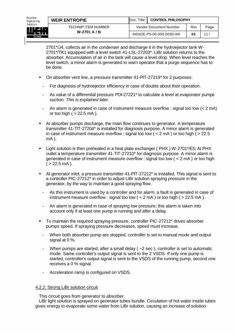
2701*/J4, collects air in the condenser and discharge it in the hydroejector tank W-2701*/TK1 equipped with a level switch 41-LSL-27203*. LiBr solution returns to the absorber. Accumulation of air in the tank will cause a level drop. When level reaches the level switch, a minor alarm is generated to warn operator that a purge sequence has to be done.
§ On absorber vent line, a pressure transmitter 41-PIT-27219* for 2 purposes:
- For diagnosis of hydroejector efficiency in case of doubts about their operation.
- As value of a differential pressure PDI-27221* to calculate a level at evaporator pumps
suction. This is explained later.
- An alarm is generated in case of instrument measure overflow : signal too low (< 2 mA) or too high ( > 22.5 mA ).
§ At absorber pumps discharge, the main flow continues to generator. A temperature
transmitter 41-TIT-27204* is installed for diagnosis purpose. A minor alarm is generated in case of instrument measure overflow : signal too low ( < 2 mA ) or too high ( > 22.5 mA ).
§ Light solution is then preheated in a heat plate exchanger ( PHX ) W-2701*/E5; At PHX
outlet a temperature transmitter 41-TIT-27210* for diagnosis purpose. A minor alarm is generated in case of instrument measure overflow : signal too low ( < 2 mA ) or too high ( > 22.5 mA ).
§ At generator inlet, a pressure transmitter 41-PIT-27212* is installed. This signal is sent to
a controller PIC-27212* in order to adjust LiBr solution spraying pressure in the generator, by the way to maintain a good spraying flow.
- As this instrument is used by a controller and for alarm, a fault is generated in case of
instrument measure overflow : signal too low ( < 2 mA ) or too high ( > 22.5 mA ).
- An alarm is generated in case of spraying low pressure; this alarm is taken into account only if at least one pump is running and after a delay.
§ To maintain the required spraying pressure, controller PIC-27212* drives absorber
pumps speed. If spraying pressure decreases, speed must increase.
- When both absorber pump are stopped, controller is set to manual mode and output signal at 0 %.
- When pumps are started, after a small delay ( ~2 sec ), controller is set to automatic
mode. Same controller's output signal is sent to the 2 VSDS. If only one pump is started, controller's output signal is sent to the VSDS of the running pump, second one receives a 0 % signal.
- Acceleration ramp is configured on VSDS.
4.2.2. Strong LiBr solution circuit
This circuit goes from generator to absorber. LiBr light solution is sprayed on generator tubes bundle. Circulation of hot water inside tubes
gives energy to evaporate some water from LiBr solution, causing an increase of solution
Vendor Document Number 04042E-PS-00-000-0030-000
Rev
03 Page
12 / 29292
CONTROL PHILOSOPHY Doc. Title:
TECHNIP ITEM NUMBER W-2701 A / B
WEIR ENTROPIE
concentration; LiBr solution becomes strong solution. Vapor resulting from evaporation goes to condenser.
Strong LiBr solution ( Lithium Bromide solution at higher concentration) is taken by generator
pumps W-2701*/P3A and P3B. In normal operation, both pumps are running, each pump is able to carry LiBr solution if the other is not available.
§ At the suction of these pumps, a level transmitter 41-LIT-27203* is installed to drive
pumps speed by controller LIC-27203*, and to protect against a low level.
- As this instrument is used by a controller and for alarm, a fault is generated in case of instrument measure overflow : signal too low ( < 2 mA ) or too high ( > 22.5 mA ).
§ When the low level is detected, pumps stop.
- In manual mode, restart order is given by operator only if level is OK
- In automatic mode, a sequence will give a start order when level is OK ( LI-27203*
above a threshold ) and after a delay. 5 start-up are allowed, a counter checks start-up number and will generate a fault causing a unit stop sequence if counter is over. If after a re-start, pumps run enough time, counter is re-initialised to 5.
§ At generator outlet, the level transmitter 41-LIT-27203* is installed. This signal is sent to
a controller LIC-27203* in order to adjust a sufficient LiBr strong solution level at pumps suction.
- As this instrument is used by a controller and for alarm, a fault is generated in case of
instrument measure overflow : signal too low ( < 2 mA ) or too high ( > 22.5 mA ). § To maintain the required suction level, controller LIC-27203* drives generator pumps
speed. If level decreases, speed must decrease.
- When both generator pumps are stopped, controller is set to manual mode and output signal at 0 %.
- When pumps are started, after a small delay ( ~2 sec ), controller is set to automatic
mode. Same controller's output signal is sent to the 2 VSDS. If only one pump is started, controller's output signal is sent to the VSDS of the running pump, second one receives a 0 % signal.
- Acceleration ramp is configured on VSDS. § generator pumps (centrifugal) are special design with canned motor (motor cooled by the
solution).
- A thermo-switch ( 41-TSHH-27225* and 41-TSHH-27226*) inside each stator protects the motor against very high temperature. Each switch is connected to the STS. It generate an alarm in case of failure, and stop the concerned pump.
- Pumps are driven by a variable speed drive system (VSDS): 41-SY-27205* and 41-SY-
27206*. Speed is controlled by a controller LIC-27203* in order to maintain a sufficient level at pump suction. Drive signal is a 4-20 mA, which will adjust pump speed between a minimum and maximum speed. These limits are configured directly on the VSDS.
Vendor Document Number 04042E-PS-00-000-0030-000
Rev
03 Page
13 / 29292
CONTROL PHILOSOPHY Doc. Title:
TECHNIP ITEM NUMBER W-2701 A / B
WEIR ENTROPIE
- Start order ( MXSH 27205* / MXSH 27206*) and Stop order ( MXSL 27205* / MXSL 27206* ) come from the DCS via STS.
- Running status ( MS 27205* / MS 27206* ) and trip status ( MA 27205* / MA 27206* )
are connected to the DCS. Reset of VSDS alarm is done on VSDS panel and not directly from DCS.
- For each pump, an alarm (run discrepancy alarm) is generated if a pump is required
ON and status not confirmed by signal MS-272xx* after a delay.
- Unavailability of the 2 pumps will cause a unit stop sequence.
- While chiller is running in automatic mode, it is possible to switch only one pump in manual mode and only if the other pump is not tripped. If a pump is in manual mode, selection of automatic mode will cause an auto-start of this pump or will be kept running if it was already running in manual mode.
§ At generator pumps discharge, a temperature transmitter 41-TIT-27208* is installed for
many purposes, notably for alarms and a controller.
- As this instrument is used by a controller and for alarm, a fault is generated in case of instrument measure overflow : signal too low ( < 2 mA ) or too high ( > 22.5 mA ).
- After subtracting to 41-TIT-27208* the value of condensate temperature 41-TIT-
27212*, the result TDI-27215*, characterizing strong solution concentration, is used by special sequences and controller TDIC-27215*; Function of this controller is described later, as it is used for chiller capacity control.
§ Strong solution is then cooled down in the heat plate exchanger ( PHX ) W-2701*/E5, in
order to spray the strong solution in the absorber at a temperature near its equilibrium temperature.
§ At PHX outlet a temperature transmitter 41-TIT-27206* for diagnosis purpose. A minor
alarm is generated in case of instrument measure overflow : signal too low ( < 2 mA ) or too high ( > 22.5 mA ).
§ At absorber inlet, a pressure transmitter 41-PIT-27207* is installed to monitor spraying
pressure.
- An alarm is generated in case of instrument measure overflow : signal too low (< 2 mA) or too high ( > 22.5 mA ).
- An alarm is generated in case of absorber spraying low pressure; this alarm is taken
into account only if at least one generator pump is running and after a delay.
§ Between generator and absorber is existing a U-tube, used by LiBr light solution when only vacuum system is in operation ( absorber pumps only in operation ), and also in case of problem on strong solution circuit, this U-tube is for generator overflow.
- A temperature transmitter 41-TIT-27218* is installed. An alarm is generated if TI-
27218* goes above a threshold.
- A minor alarm is generated in case of instrument measure overflow : signal too low (< 2 mA) or too high ( > 22.5 mA ).
Vendor Document Number 04042E-PS-00-000-0030-000
Rev
03 Page
14 / 29292
CONTROL PHILOSOPHY Doc. Title:
TECHNIP ITEM NUMBER W-2701 A / B
WEIR ENTROPIE
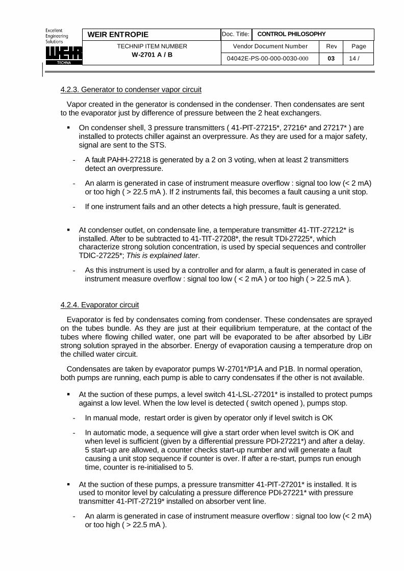
4.2.3. Generator to condenser vapor circuit
Vapor created in the generator is condensed in the condenser. Then condensates are sent
to the evaporator just by difference of pressure between the 2 heat exchangers. § On condenser shell, 3 pressure transmitters ( 41-PIT-27215*, 27216* and 27217* ) are
installed to protects chiller against an overpressure. As they are used for a major safety, signal are sent to the STS.
- A fault PAHH-27218 is generated by a 2 on 3 voting, when at least 2 transmitters
detect an overpressure.
- An alarm is generated in case of instrument measure overflow : signal too low (< 2 mA) or too high ( > 22.5 mA ). If 2 instruments fail, this becomes a fault causing a unit stop.
- If one instrument fails and an other detects a high pressure, fault is generated.
§ At condenser outlet, on condensate line, a temperature transmitter 41-TIT-27212* is installed. After to be subtracted to 41-TIT-27208*, the result TDI-27225*, which characterize strong solution concentration, is used by special sequences and controller TDIC-27225*; This is explained later.
- As this instrument is used by a controller and for alarm, a fault is generated in case of
instrument measure overflow : signal too low ( < 2 mA ) or too high ( > 22.5 mA ).
4.2.4. Evaporator circuit Evaporator is fed by condensates coming from condenser. These condensates are sprayed
on the tubes bundle. As they are just at their equilibrium temperature, at the contact of the tubes where flowing chilled water, one part will be evaporated to be after absorbed by LiBr strong solution sprayed in the absorber. Energy of evaporation causing a temperature drop on the chilled water circuit.
Condensates are taken by evaporator pumps W-2701*/P1A and P1B. In normal operation, both pumps are running, each pump is able to carry condensates if the other is not available.
§ At the suction of these pumps, a level switch 41-LSL-27201* is installed to protect pumps
against a low level. When the low level is detected ( switch opened ), pumps stop.
- In manual mode, restart order is given by operator only if level switch is OK
- In automatic mode, a sequence will give a start order when level switch is OK and when level is sufficient (given by a differential pressure PDI-27221*) and after a delay. 5 start-up are allowed, a counter checks start-up number and will generate a fault causing a unit stop sequence if counter is over. If after a re-start, pumps run enough time, counter is re-initialised to 5.
§ At the suction of these pumps, a pressure transmitter 41-PIT-27201* is installed. It is
used to monitor level by calculating a pressure difference PDI-27221* with pressure transmitter 41-PIT-27219* installed on absorber vent line.
- An alarm is generated in case of instrument measure overflow : signal too low (< 2 mA)
or too high ( > 22.5 mA ).
Vendor Document Number 04042E-PS-00-000-0030-000
Rev
03 Page
15 / 29292
CONTROL PHILOSOPHY Doc. Title:
TECHNIP ITEM NUMBER W-2701 A / B
WEIR ENTROPIE
- In automatic mode, when PDI-27221* is above a threshold, evaporator pump are
authorized to start (and if some other conditions are OK).
§ Evaporator pumps (centrifugal) are special design with canned motor (motor cooled by the solution).
- A thermo-switch ( 41-TSHH-27221* and 41-TSHH-27222*) inside each stator protects
the motor against very high temperature. Each switch is connected to the STS. It generates an alarm in case of failure, and stops the concerned pump.
- Pumps are driven by a variable speed drive system (VSDS): 41-SY-27201* and 41-SY-27202*. Speed is controlled by a controller PIC-27207* in order to maintain a sufficient spraying pressure ( spraying flow ) in the evaporator. Drive signal is a 4-20 mA, which will adjust pump speed between a minimum and maximum speed. These limits are configured directly on the VSDS.
- Start order ( MXSH 27201* / MXSH 27202*) and Stop order ( MXSL 27201* / MXSL
27202* ) come from the DCS via STS.
- Running status ( MS 27201* / MS 27202* ) and trip status ( MA 27201* / MA 27202* ) are connected to the DCS. Reset of VSDS alarm is done on VSDS panel and not directly from DCS.
- For each pump, an alarm (run discrepancy alarm) is generated if a pump is required
ON and status not confirmed by signal MS-272xx* after a delay.
- While chiller is running in automatic mode, it is possible to switch only one pump in manual mode and only if the other pump is not tripped. If a pump is in manual mode, selection of automatic mode will cause an auto-start of this pump or will be kept running if it was already running in manual mode.
- Unavailability of the 2 pumps will cause a unit stop sequence.
§ At evaporator pumps discharge, a main pipe send condensate to the evaporator
spraying system. Condensates, for dilution purpose, may also be sent to the absorber through a smaller pipe, where is installed a dilution shut-off valve 41-XV-27215* .
- Dilution shut-off valve 41-XV-27215* is equipped with 2 limit switches for close and
open positions.
- An alarm ( closing discrepancy ) is generated if the valve is required closed 41-XY-27215* de-energized and, after a delay, limit switch 41-XZSL-27215* is not activated (contact not closed).
- An alarm ( opening discrepancy ) is generated if the valve is required open 41-XY-
27215* energized and, after a delay, limit switch 41-XZSH-27215* is not activated (contact not closed).
- Solenoid valve 41-XY-27215* operates in the same mode of the whole unit, it is not
possible to put the solenoid in manual mode while unit is in automatic mode. If operator wants to open this valve during operation of the unit in automatic mode, he must launch a "dilution sequence" by clicking on the dedicated soft button on operator station.
Vendor Document Number 04042E-PS-00-000-0030-000
Rev
03 Page
16 / 29292
CONTROL PHILOSOPHY Doc. Title:
TECHNIP ITEM NUMBER W-2701 A / B
WEIR ENTROPIE
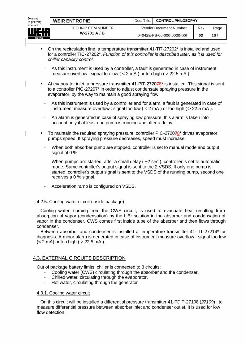
§ On the recirculation line, a temperature transmitter 41-TIT-27202* is installed and used for a controller TIC-27202*. Function of this controller is described later, as it is used for chiller capacity control.
- As this instrument is used by a controller, a fault is generated in case of instrument
measure overflow : signal too low ( < 2 mA ) or too high ( > 22.5 mA ).
§ At evaporator inlet, a pressure transmitter 41-PIT-272078* is installed. This signal is sent to a controller PIC-27207* in order to adjust condensate spraying pressure in the evaporator, by the way to maintain a good spraying flow.
- As this instrument is used by a controller and for alarm, a fault is generated in case of
instrument measure overflow : signal too low ( < 2 mA ) or too high ( > 22.5 mA ).
- An alarm is generated in case of spraying low pressure; this alarm is taken into account only if at least one pump is running and after a delay.
§ To maintain the required spraying pressure, controller PIC-272078* drives evaporator
pumps speed. If spraying pressure decreases, speed must increase.
- When both absorber pump are stopped, controller is set to manual mode and output signal at 0 %.
- When pumps are started, after a small delay ( ~2 sec ), controller is set to automatic
mode. Same controller's output signal is sent to the 2 VSDS. If only one pump is started, controller's output signal is sent to the VSDS of the running pump, second one receives a 0 % signal.
- Acceleration ramp is configured on VSDS.
4.2.5. Cooling water circuit (inside package)
Cooling water, coming from the CWS circuit, is used to evacuate heat resulting from
absorption of vapor (condensation) by the LiBr solution in the absorber and condensation of vapor in the condenser. CWS comes first inside tube of the absorber and then flows through condenser.
Between absorber and condenser is installed a temperature transmitter 41-TIT-27214* for diagnosis. A minor alarm is generated in case of instrument measure overflow : signal too low (< 2 mA) or too high ( > 22.5 mA ).
4.3. EXTERNAL CIRCUITS DESCRIPTION
Out of package battery limits, chiller is connected to 3 circuits: - Cooling water (CWS) circulating through the absorber and the condenser, - Chilled water, circulating through the evaporator, - Hot water, circulating through the generator
4.3.1. Cooling water circuit
On this circuit will be installed a differential pressure transmitter 41-PDIT-27108 (27109) , to measure differential pressure between absorber inlet and condenser outlet. It is used for low flow detection.
Vendor Document Number 04042E-PS-00-000-0030-000
Rev
03 Page
17 / 29292
CONTROL PHILOSOPHY Doc. Title:
TECHNIP ITEM NUMBER W-2701 A / B
WEIR ENTROPIE
§ When PDI-27108 (27109) is below a threshold, a fault is generated, causing a unit stop sequence.
§ As this instrument is used by a controller, a fault is generated in case of instrument
measure overflow : signal too low ( < 2 mA ) or too high ( > 22.5 mA ).
4.3.2. Chilled water circuit At evaporator inlet, a flow control valve 41-TV-27103 / 41-TV-27104 is installed to adjust
chilled water flow. Control philosophy is a Technip scope. At evaporator outlet, a temperature transmitter ( 41-TIT-27112 / 41-TIT-27113 ) is installed.
This temperature is used by a controller TIC-27112 (27113) to adjust chiller capacity, and to generate alarm and fault. Controller is explained later.
§ When value TI-27112 is below a first threshold, a low temperature alarm is generated.
§ When value TI-27112 is below a second threshold, a very low temperature fault is
generated, causing a unit stop sequence. § As this instrument is used by a controller, a fault is generated in case of instrument
measure overflow : signal too low ( < 2 mA ) or too high ( > 22.5 mA ).
4.3.3. Hot water circuit At generator inlet, a temperature control valve 41-TV-27112 / 41-TV-27113 is installed to
control hot water flow through the generator and by the way to adjust chiller capacity. This valve is driven by controller TIC-27112 / TIC-27113 .
§ This valve is equipped with a close position limit switch 41-TZSL-27112 (41-TZSL-
27113).
- An alarm ( closing discrepancy ) is generated if valve is required closed (solenoid 41-TY-27112 de-energized or positioning signal = 0 %) and, after a delay, limit switch not activated (contact not closed).
§ Solenoid valve 41-TY-27112 (27113) is driven from STS. Valve operates in the same
mode of the whole unit, it is not possible to put the solenoid in manual mode while unit is in automatic mode.
§ Solenoid valve 41-TY-27112 (27113) is de-energized (safety interlock) in case of
condenser very high pressure PAHH-27218*. 4.4. LiBr STRONG SOLUTION CONCENTRATION CONTROL
As mentioned in paragraph 4.2.2 and 4.2.3, LiBr strong solution concentration can be characterized by the temperature difference TDI-27215*. This value is used by a controller TDIC-27215* which is a part of chiller capacity control (see § 5.5), and also for some sequences.
Vendor Document Number 04042E-PS-00-000-0030-000
Rev
03 Page
18 / 29292
CONTROL PHILOSOPHY Doc. Title:
TECHNIP ITEM NUMBER W-2701 A / B
WEIR ENTROPIE
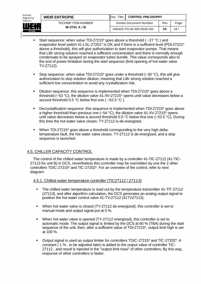
§ Start sequence: when value TDI-27215* goes above a threshold ( ~27 °C ) and evaporator level switch 41-LSL-27201* is OK and if there is a sufficient level (PDI-27221* above a threshold), this will give authorization to start evaporator pumps. That means that LiBr strong solution reached a sufficient concentration and there is normally enough condensate to be sprayed on evaporator tubes bundle. This value corresponds also to the end of power limitation during the start sequence (limit opening of hot water valve TV-27112).
§ Stop sequence: when value TDI-27215* goes under a threshold (~30 °C), this will give
authorization to stop solution dilution, meaning that LiBr strong solution reached a sufficient low concentration to avoid any crystallization risk.
§ Dilution sequence: this sequence is implemented when TDI-27215* goes above a
threshold (~53 °C), the dilution valve 41-XV-27215* opens until value decreases below a second threshold 0.5 °C below first one ( ~52.5 °C ).
§ Decrystallization sequence: this sequence is implemented when TDI-27215* goes above
a higher threshold than previous one (~54 °C), the dilution valve 41-XV-27215* opens until value decreases below a second threshold 0.5 °C below first one (~53.5 °C). During this time the hot water valve closes: TY-27112 is de-energized.
§ When TDI-27215* goes above a threshold corresponding to the very high delta-
temperature fault, the hot water valve closes: TY-27112 is de-energized, and a stop sequence is launched.
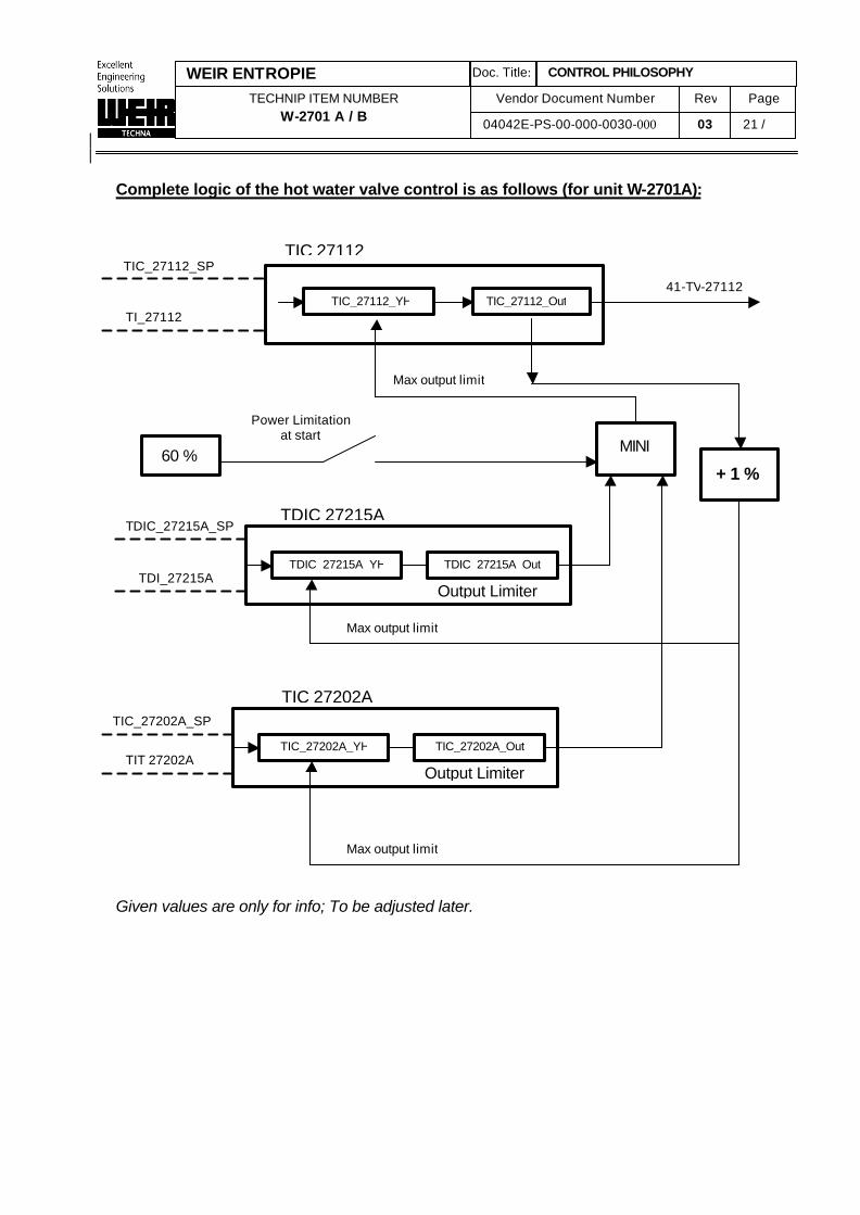
4.5. CHILLER CAPACITY CONTROL
The control of the chilled water temperature is made by a controller 41-TIC-27112 (41-TIC-27113 for unit B) in DCS, nevertheless this controller may be overridden by one the 2 other controllers TDIC-27215* and TIC-27202*. For an overview of the control, refer to next diagram.
4.5.1. Chilled water temperature controller (TIC27112 / 27113)
§ The chilled water temperature is read out by the temperature transmitter 41-TIT-27112
(27113), and after algorithm calculation, the DCS generates an analog output signal to position the hot water control valve 41-TV-27112 (41TV27113).
§ When hot water valve is closed (TY-27112 de-energized), this controller is set to
manual mode and output signal put at 0 %. § When hot water valve is opened (TY-27112 energized), this controller is set to
automatic mode. The output signal is limited by the DCS at 60 % (TBA) during the start sequence of the unit, then, after a sufficient value of TDI-27215*, output limit high is set at 100 %.
§ Output signal is used as output limiter for controllers TDIC-27215* and TIC-27202*. A
constant ( 1 % , to be adjusted later) is added to the output value of controller TIC-27112 , and result is injected in the "output limit maxi" of other controllers; By this way, response of other controllers is faster.
Vendor Document Number 04042E-PS-00-000-0030-000
Rev
03 Page
19 / 29292
CONTROL PHILOSOPHY Doc. Title:
TECHNIP ITEM NUMBER W-2701 A / B
WEIR ENTROPIE
§ Conversely, the 2 other controllers TDIC-27215* and TIC-27202* may do the same in case of their parameter's drift. Output signals of these controllers are compared, and the minimum value is used as output limiter for the main controller TIC-27112.
§ If chilled water temperature increases, output signal increase.
§ The actual chilled water temperature and the temperature set point and the valve
position are displayed on Operator station.
§ This controller may be equally switched to automatic or manual mode.
Delta-Temperature TDI-27215* between condenser W-2701*/E4 and generator W-2701*/E3 is controlled by a temperature differential control system 41-TDIC-27215*, preventing from crystallisation due to too high concentration caused by a unit overload or bad absorption efficiency (too much air inside chiller ).
§ This controller is an output limiter for TIC-27112.
§ The temperature differenceTDI-27215* is equal to : TIT27208* - TIT27212* . All values
are displayed on operator station. § When hot water valve is closed (TY-27112 de-energized), this controller is set to
manual mode and output signal put at 0 %. § If differential temperature TDI-27215* increases, output signal decreases.
§ Output signal of this controller is compared to output signal of controller TIC 27202*,
and the minimum value is used as output limiter for the main controller TIC-27112.
§ Maximum output limit is taken from actual signal output of TIC-27112 added of a constant ( refer § 4.5.1 ).
§ This controller may be equally switched to automatic or manual mode.
4.5.3. Evaporator Temperature Controller TIC-27202*
Temperature in evaporator is controlled by a temperature controller TIC 27202*. This controller is mainly useful for transitional phenomenon such as sudden drop of chilled
water requirement. § This controller is an output limiter for TIC-27112.
§ When hot water valve is closed (TY-27112 de-energized), this controller is set to manual mode and output signal put at 0 %.
§ If temperature TI-27202* decreases, output signal decreases.
§ Output signal of this controller is compared to output signal of controller TDIC 27215*, and the minimum value is used as output limiter for the main controller TIC-27112.
Vendor Document Number 04042E-PS-00-000-0030-000
Rev
03 Page
20 / 29292
CONTROL PHILOSOPHY Doc. Title:
TECHNIP ITEM NUMBER W-2701 A / B
WEIR ENTROPIE
§ Maximum output limit is taken from actual signal output of TIC-27112 added of a constant ( refer § 4.5.1 ).
§ This controller may be equally switched to automatic or manual mode.
Vendor Document Number 04042E-PS-00-000-0030-000
Rev
03 Page
21 / 29292
CONTROL PHILOSOPHY Doc. Title:
TECHNIP ITEM NUMBER W-2701 A / B
WEIR ENTROPIE
Output Limiter
Output Limiter
Complete logic of the hot water valve control is as follows (for unit W-2701A):
Given values are only for info; To be adjusted later.
TI_27112
TIC 27112
TIC_27112_YH
Max output limit
TDIC_27215A_SP
TDI_27215A
TIC_27112_SP
TDIC 27215A
TIC_27202A_SP
TIT 27202A
TIC 27202A
TIC_27112_Out
TDIC_27215A_YH
TIC_27202A_YH TIC_27202A_Out
TDIC_27215A_Out
MINI
+ 1 %
41-TV-27112
Max output limit
Max output limit
60 %
Power Limitation at start
Vendor Document Number 04042E-PS-00-000-0030-000
Rev
03 Page
22 / 29292
CONTROL PHILOSOPHY Doc. Title:
TECHNIP ITEM NUMBER W-2701 A / B
WEIR ENTROPIE
5. SEQUENCES DESCRIPTION
7 sequences are implemented when unit is in automatic mode: § Start sequence § Stop sequence § Decrystallization sequence § Dilution sequence § Evaporator pump sequence § Absorber pump sequence § Generator pump sequence
5.1. START SEQUENCE
This sequence is OFF (no step active) if unit is in manual mode, or in case a fault is active, or if stop sequence is in progress. q Step 1 : is the initial step, waiting for start order
q Transition 1: conditions to go to step 2
- start is required and - - at least one pump available on each circuit (1 evaporator pump, 1 absorber pump and
1 generator pump) and - permissive to start is OK
q Step 2:
- Equipment are re-initialised to automatic mode - Timer 2 seconds
q Transition 2: conditions to go to step 3
- Time over
q Step 3: - Authorize absorber pumps sequence ( start pumps W-2701*/P2 A/B ) - Start generator spraying controller PIC-27212* ( set to auto mode ) - Status unit starting - Timer 60 seconds
q Transition 3: conditions to go to step 4
- Time over and - Sufficient level in generator and - Sufficient generator spraying pressure and - At least one absorber pump running
q Step 4:
- Authorize generator pumps sequence ( start pumps W-2701*/P3 A/B ) - Start generator level controller LIC-27203* ( set to auto mode ) - Timer 60 seconds
q Transition 4: conditions to go to step 5
- Time over and - Sufficient absorber spraying pressure and
Vendor Document Number 04042E-PS-00-000-0030-000
Rev
03 Page
23 / 29292
CONTROL PHILOSOPHY Doc. Title:
TECHNIP ITEM NUMBER W-2701 A / B
WEIR ENTROPIE
- At least one generator pump running
q Step 5: - Power limitation active: max opening for TV-27112 = 60 % - Timer 1 seconds
q Transition 5: conditions to go to step 6
- Time over and
q Step 6: - Open hot water control valve (Controllers TIC-27112, TDIC-27215* and TIC-27202* set
to automatic mode) - .
q Transition 6: conditions to go to step 7
- Delta-temperature TDI-27215* sufficient and - Evaporator level switch 41-LSL-27201* OK and - Sufficient level at evaporator pump suction : PDI-27221* OK