5" Bookshelf Speaker Kit Instructions Congratulations on the purchase of your new 5" Bookshelf Speaker Kit! It contains the audio components necessary to wire two speakers. Just build your own custom speaker boxes and enjoy quality sound! Please read these instructions fully before building your boxes or wiring your speakers.
Transcript
5" Bookshelf Speaker Kit Instructions
Congratulations on the purchase of your new 5" Bookshelf Speaker Kit! It contains the audio components necessary to wire two speakers. Just build your own custom speaker boxes and enjoy quality sound! Please read these instructions fully before building your boxes or wiring your speakers.
2
Make Speaker Boxes1. Build your speaker boxes out of MDF, particleboard, hardwood plywood or solid wood. For 3/4" material, the outside dimensions of the box should be 111⁄4" H x 71⁄4" W x 81⁄2" D. Whatever the thickness of your material, the interior dimensions of the speaker box should be 93⁄4" H x 53⁄4" W x 7" D.
2. For each box, follow the Drilling Diagram carefully to locate and cut the openings for the Woofer (1), Tweeter (2), Terminal Cup (3) and air tube.
3. Apply the finish of your choice.
4. Using the Woofers (1), Tweeters(2) and Terminal Cups (3) as guides in their holes, mark and drill pilot holes for the #6 x 5/8" Mounting Screws (9). (Use a 3/32" bit for hardwoods and a 1/16" bit for softwoods.)
5. Divide the Poly Fill (10) and secure half to the inside back face of each speaker box with glue or another adhesive. Spread the fill to avoid obstructing the openings in the back of the box.
Quantity
1 5" USA Woofer 2 2 1" Silk Dome Tweeter 2 3 Terminal Cup 2 4 4' Speaker Wire 2 5 Capacitor 2 6 Butt Connector 2 7 Small Terminal Clip 2 8 Large Terminal Clip 10 9 #6x5/8" Mounting Screws (Not Shown) 2210 Poly Fill 1
PARTS LIST - 5" BOOKCASE SPEAKER KIT
10
11
3 24
5
7
8 62
3
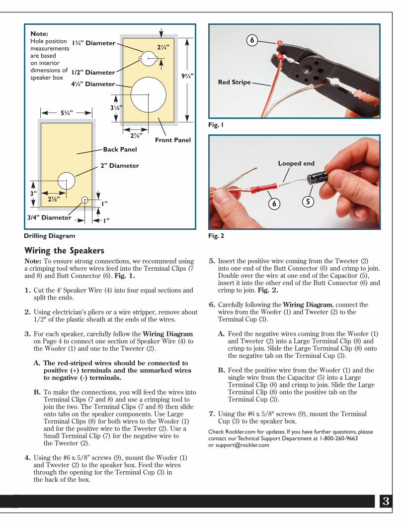
Wiring the SpeakersNote: To ensure strong connections, we recommend using a crimping tool where wires feed into the Terminal Clips (7 and 8) and Butt Connector (6). Fig. 1.
1. Cut the 4' Speaker Wire (4) into four equal sections and split the ends.
2. Using electrician’s pliers or a wire stripper, remove about 1/2" of the plastic sheath at the ends of the wires.
3. For each speaker, carefully follow the Wiring Diagram on Page 4 to connect one section of Speaker Wire (4) to the Woofer (1) and one to the Tweeter (2).
A. The red-striped wires should be connected to positive (+) terminals and the unmarked wires to negative (-) terminals.
B. To make the connections, you will feed the wires into Terminal Clips (7 and 8) and use a crimping tool to join the two. The Terminal Clips (7 and 8) then slide onto tabs on the speaker components. Use Large Terminal Clips (8) for both wires to the Woofer (1) and for the positive wire to the Tweeter (2). Use a Small Terminal Clip (7) for the negative wire to the Tweeter (2).
4. Using the #6 x 5/8” screws (9), mount the Woofer (1) and Tweeter (2) to the speaker box. Feed the wires through the opening for the Terminal Cup (3) in the back of the box.
Check Rockler.com for updates. If you have further questions, pleasecontact our Technical Support Department at 1-800-260-9663 or [email protected]
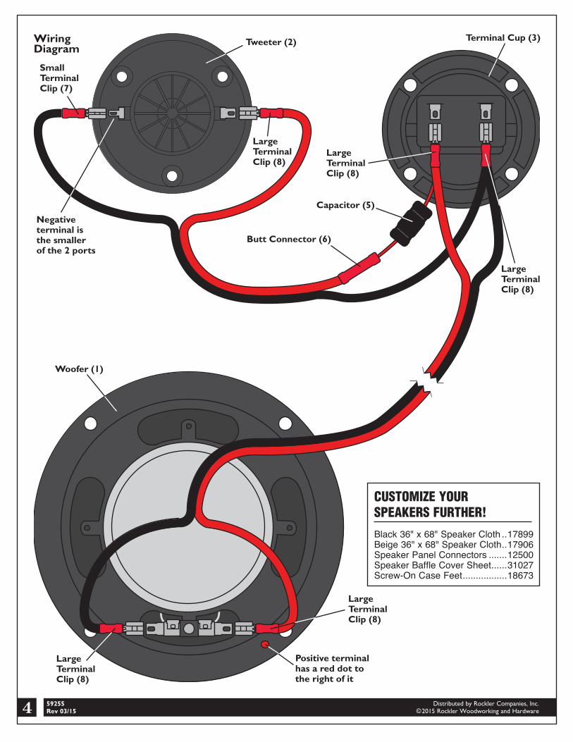
Fig. 2
Fig. 1
5. Insert the positive wire coming from the Tweeter (2) into one end of the Butt Connector (6) and crimp to join. Double over the wire at one end of the Capacitor (5), insert it into the other end of the Butt Connector (6) and crimp to join. Fig. 2.
6. Carefully following the Wiring Diagram, connect the wires from the Woofer (1) and Tweeter (2) to the Terminal Cup (3).
A. Feed the negative wires coming from the Woofer (1) and Tweeter (2) into a Large Terminal Clip (8) and crimp to join. Slide the Large Terminal Clip (8) onto the negative tab on the Terminal Cup (3).
B. Feed the positive wire from the Woofer (1) and the single wire from the Capacitor (5) into a Large Terminal Clip (8) and crimp to join. Slide the Large Terminal Clip (8) onto the positive tab on the Terminal Cup (3).
7. Using the #6 x 5/8" screws (9), mount the Terminal Cup (3) to the speaker box.
6 5
Looped end
6
1"
1"
27⁄8"3"
53⁄4"31⁄8"
27⁄8"
21⁄4"
93⁄4"1/2" Diameter
13⁄4" Diameter
41⁄4" Diameter
2" Diameter
3/4" Diameter
Front PanelBack Panel
Note: Hole position measurements are based on interior dimensions of speaker box