Chemicals Tutorial 5-1 5-1 5 Chemicals Tutorial In this Tutorial, a flowsheet for the production of propylene glycol is presented. Propylene oxide is combined with water to produce propylene glycol in a continuously-stirred-tank reactor (CSTR). The reactor outlet stream is then fed to a distillation tower, where essentially all the glycol is recovered in the tower bottoms. A flowsheet for this process is shown below. The following pages will guide you through building a HYSYS case for modelling this process. This example will illustrate the complete construction of the simulation, from selecting a property package and components, defining the reaction, to installing streams and unit operations, through to examining the final results. The tools available in HYSYS interface will be utilized to illustrate the flexibility available to you. At this point, your Session Preferences view should be open. If not, select Preferences from the Tools menu. Then move to the Units page on the Variables tab by clicking on it. tutorial has been pre-built and is located in the file TUTOR3.HSC in your HYSYS\SAMPLES directory. Figure 5.1 Before proceeding, you should have read Chapter 1 - Introduction which precedes the Tutorials in this manual.
Transcript
Chemicals Tutorial 5-1
5-1
5 Chemicals Tutorial
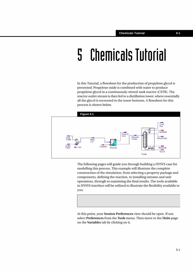
In this Tutorial, a flowsheet for the production of propylene glycol is presented. Propylene oxide is combined with water to produce propylene glycol in a continuously-stirred-tank reactor (CSTR). The reactor outlet stream is then fed to a distillation tower, where essentially all the glycol is recovered in the tower bottoms. A flowsheet for this process is shown below.
The following pages will guide you through building a HYSYS case for modelling this process. This example will illustrate the complete construction of the simulation, from selecting a property package and components, defining the reaction, to installing streams and unit operations, through to examining the final results. The tools available in HYSYS interface will be utilized to illustrate the flexibility available to you.
At this point, your Session Preferences view should be open. If not, select Preferences from the Tools menu. Then move to the Units page on the Variables tab by clicking on it.
The complete case for this tutorial has been pre-built and is located in the file TUTOR3.HSC in your HYSYS\SAMPLES directory.
Figure 5.1
Before proceeding, you should have read Chapter 1 - Introduction which precedes the Tutorials in this manual.
5-2 Chemicals Tutorial
5-2
Creating a New Unit Set
The first step in building the simulation case is choosing a unit set. HYSYS will not allow you to change any of the three default unit sets listed. However, you can create a new unit set by cloning an existing one. For this example, a new unit set will be made based on the HYSYS Field set, then customize the new set:
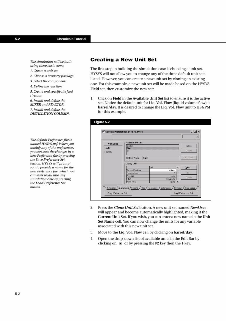
1. Click on Field in the Available Unit Set list to ensure it is the active set. Notice the default unit for Liq. Vol. Flow (liquid volume flow) is barrel/day. It is desired to change the Liq. Vol. Flow unit to USGPM for this example.
2. Press the Clone Unit Set button. A new unit set named NewUser will appear and become automatically highlighted, making it the Current Unit Set. If you wish, you can enter a new name in the Unit Set Name cell. You can now change the units for any variable associated with this new unit set.
3. Move to the Liq. Vol. Flow cell by clicking on barrel/day.
4. Open the drop-down list of available units in the Edit Bar by clicking on or by pressing the F2 key then the ���� key.
Figure 5.2
The simulation will be built using these basic steps:
1. Create a unit set.
2. Choose a property package.
3. Select the components.
4. Define the reaction.
5. Create and specify the feed streams.
6. Install and define the MIXER and REACTOR.
7. Install and define the DISTILLATION COLUMN.
The default Preference file is named HYSYS.prf. When you modify any of the preferences, you can save the changes in a new Preference file by pressing the Save Preference Set button. HYSYS will prompt you to provide a name for the new Preference file, which you can later recall into any simulation case by pressing the Load Preference Set button.
Chemicals Tutorial 5-3
5-3
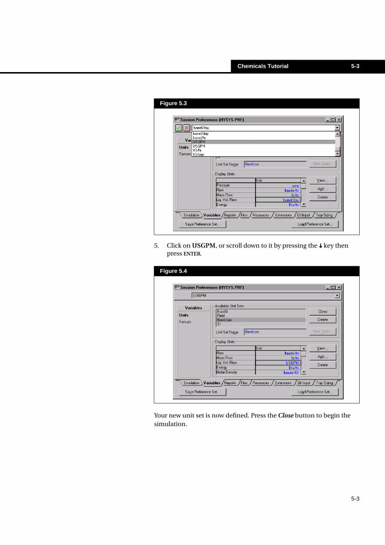
5. Click on USGPM, or scroll down to it by pressing the ���� key then press ENTER.
Your new unit set is now defined. Press the Close button to begin the simulation.
Figure 5.3
Figure 5.4
5-4 Chemicals Tutorial
5-4
Beginning the Simulation
To start a new simulation case, do one of the following:
• Select New Case from the File menu.• Press the New Case button.
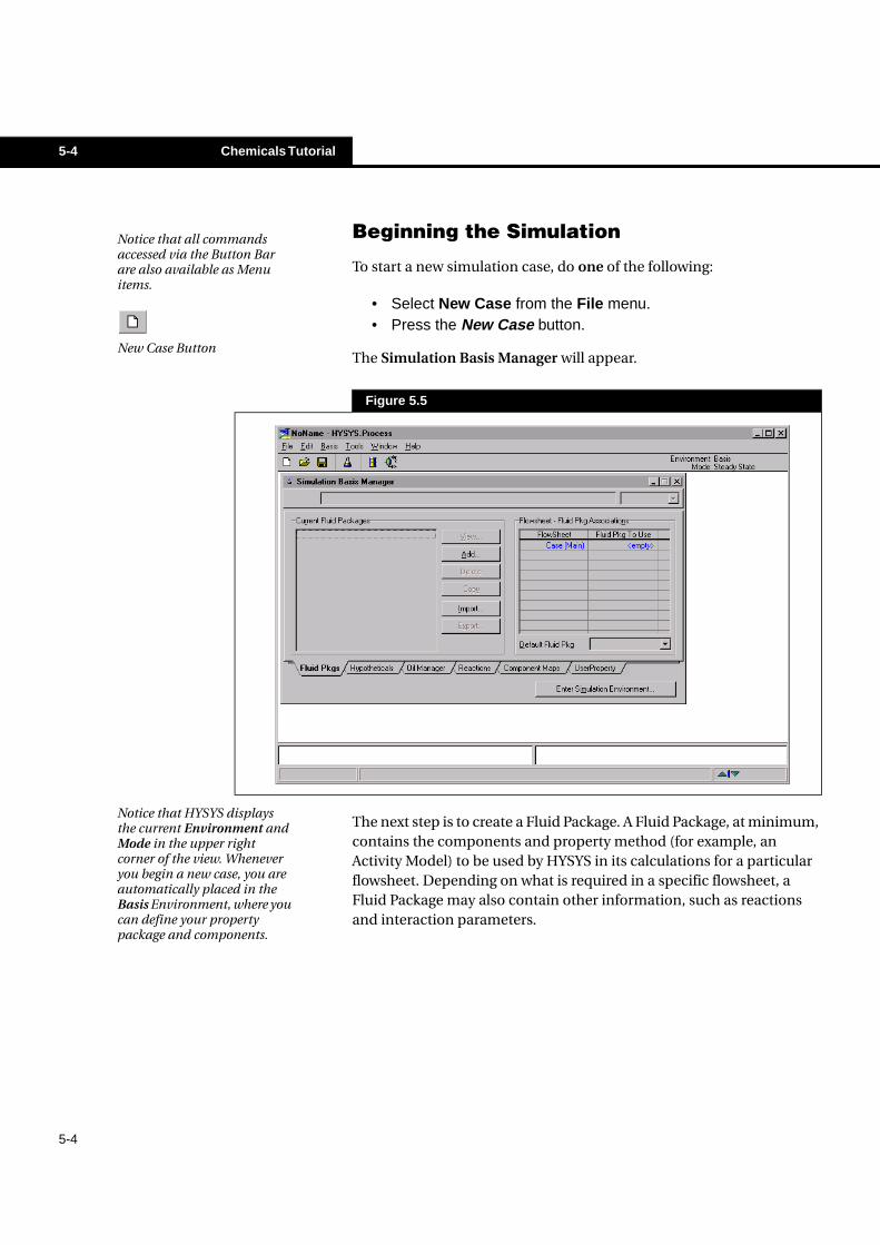
The Simulation Basis Manager will appear.
The next step is to create a Fluid Package. A Fluid Package, at minimum, contains the components and property method (for example, an Activity Model) to be used by HYSYS in its calculations for a particular flowsheet. Depending on what is required in a specific flowsheet, a Fluid Package may also contain other information, such as reactions and interaction parameters.
Notice that all commands accessed via the Button Bar are also available as Menu items.
New Case Button
Figure 5.5
Notice that HYSYS displays the current Environment and Mode in the upper right corner of the view. Whenever you begin a new case, you are automatically placed in the Basis Environment, where you can define your property package and components.
Chemicals Tutorial 5-5
5-5
Creating a Fluid Package
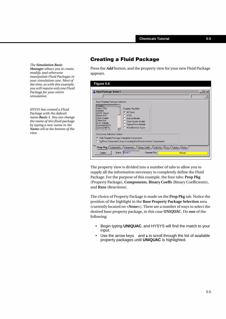
Press the Add button, and the property view for your new Fluid Package appears.
The property view is divided into a number of tabs to allow you to supply all the information necessary to completely define the Fluid Package. For the purpose of this example, the four tabs: Prop Pkg (Property Package), Components, Binary Coeffs (Binary Coefficients), and Rxns (Reactions).
The choice of Property Package is made on the Prop Pkg tab. Notice the position of the highlight in the Base Property Package Selection area (currently located on <None>). There are a number of ways to select the desired base property package, in this case UNIQUAC. Do one of the following:
• Begin typing UNIQUAC, and HYSYS will find the match to yourinput.
• Use the arrow keys and ���� to scroll through the list of availableproperty packages until UNIQUAC is highlighted.
Figure 5.6
The Simulation Basis Manager allows you to create, modify, and otherwise manipulate Fluid Packages in your simulation case. Most of the time, as with this example, you will require only one Fluid Package for your entire simulation.
HYSYS has created a Fluid Package with the default name Basis-1. You can change the name of this fluid package by typing a new name in the Name cell at the bottom of the view.
5-6 Chemicals Tutorial
5-6
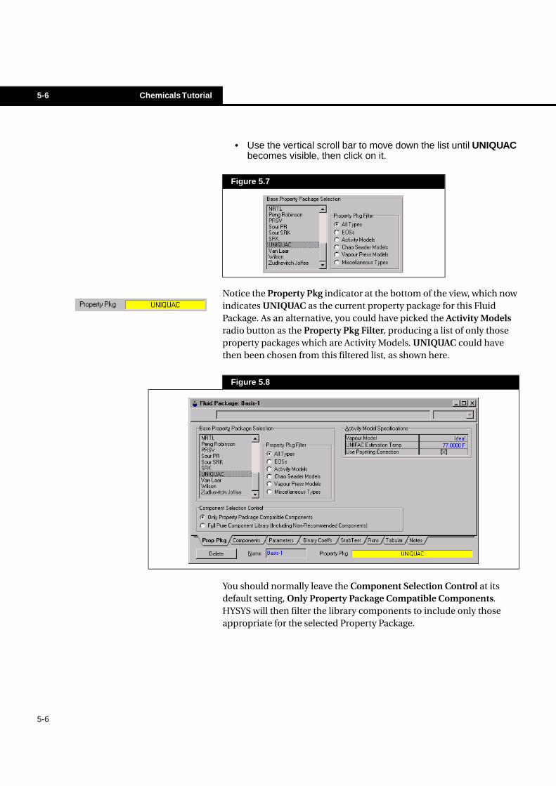
• Use the vertical scroll bar to move down the list until UNIQUACbecomes visible, then click on it.
Notice the Property Pkg indicator at the bottom of the view, which now indicates UNIQUAC as the current property package for this Fluid Package. As an alternative, you could have picked the Activity Models radio button as the Property Pkg Filter, producing a list of only those property packages which are Activity Models. UNIQUAC could have then been chosen from this filtered list, as shown here.
You should normally leave the Component Selection Control at its default setting, Only Property Package Compatible Components. HYSYS will then filter the library components to include only those appropriate for the selected Property Package.
Figure 5.7
Figure 5.8
Chemicals Tutorial 5-7
5-7
Selecting Components
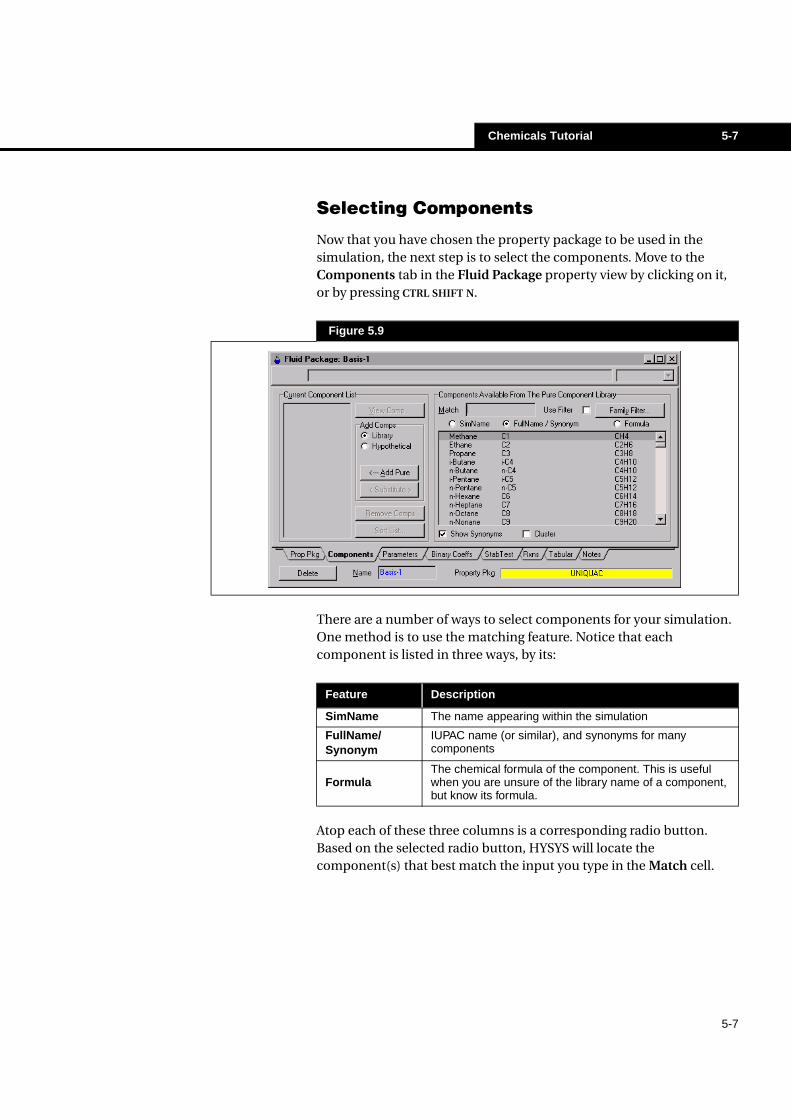
Now that you have chosen the property package to be used in the simulation, the next step is to select the components. Move to the Components tab in the Fluid Package property view by clicking on it, or by pressing CTRL SHIFT N.
There are a number of ways to select components for your simulation. One method is to use the matching feature. Notice that each component is listed in three ways, by its:
Atop each of these three columns is a corresponding radio button. Based on the selected radio button, HYSYS will locate the component(s) that best match the input you type in the Match cell.
Figure 5.9
Feature Description
SimName The name appearing within the simulation
FullName/Synonym
IUPAC name (or similar), and synonyms for manycomponents
FormulaThe chemical formula of the component. This is usefulwhen you are unsure of the library name of a component,but know its formula.
5-8 Chemicals Tutorial
5-8
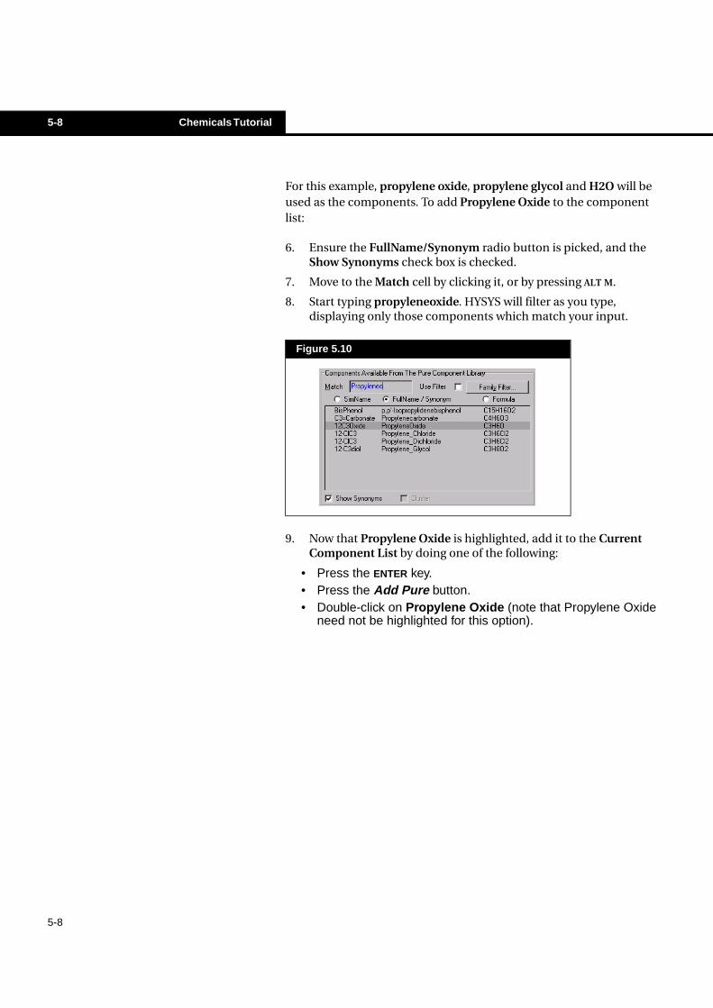
For this example, propylene oxide, propylene glycol and H2O will be used as the components. To add Propylene Oxide to the component list:
6. Ensure the FullName/Synonym radio button is picked, and the Show Synonyms check box is checked.
7. Move to the Match cell by clicking it, or by pressing ALT M.
8. Start typing propyleneoxide. HYSYS will filter as you type, displaying only those components which match your input.
9. Now that Propylene Oxide is highlighted, add it to the Current Component List by doing one of the following:
• Press the ENTER key.• Press the Add Pure button.• Double-click on Propylene Oxide (note that Propylene Oxide
need not be highlighted for this option).
Figure 5.10
Chemicals Tutorial 5-9
5-9
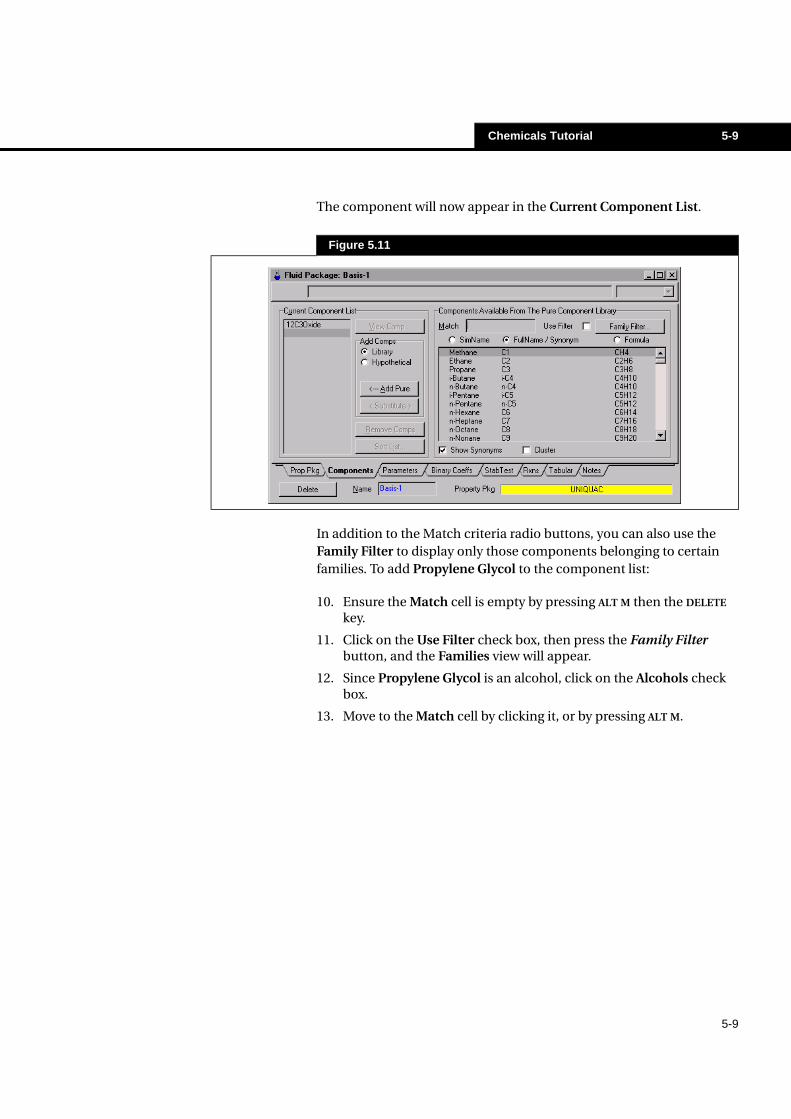
The component will now appear in the Current Component List.
In addition to the Match criteria radio buttons, you can also use the Family Filter to display only those components belonging to certain families. To add Propylene Glycol to the component list:
10. Ensure the Match cell is empty by pressing ALT M then the DELETE key.
11. Click on the Use Filter check box, then press the Family Filter button, and the Families view will appear.
12. Since Propylene Glycol is an alcohol, click on the Alcohols check box.
13. Move to the Match cell by clicking it, or by pressing ALT M.
Figure 5.11
5-10 Chemicals Tutorial
5-10
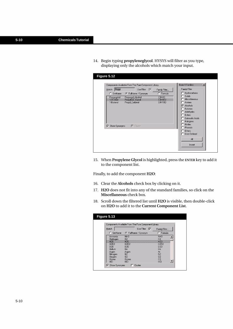
14. Begin typing propyleneglycol. HYSYS will filter as you type, displaying only the alcohols which match your input.
15. When Propylene Glycol is highlighted, press the ENTER key to add it to the component list.
Finally, to add the component H2O:
16. Clear the Alcohols check box by clicking on it.
17. H2O does not fit into any of the standard families, so click on the Miscellaneous check box.
18. Scroll down the filtered list until H2O is visible, then double-click on H2O to add it to the Current Component List.
Figure 5.12
Figure 5.13
Chemicals Tutorial 5-11
5-11
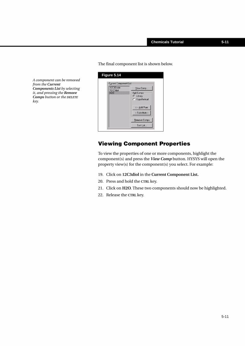
The final component list is shown below.
Viewing Component Properties
To view the properties of one or more components, highlight the component(s) and press the View Comp button. HYSYS will open the property view(s) for the component(s) you select. For example:
19. Click on 12C3diol in the Current Component List.
20. Press and hold the CTRL key.
21. Click on H2O. These two components should now be highlighted.
22. Release the CTRL key.
Figure 5.14A component can be removed from the Current Components List by selecting it, and pressing the Remove Comps button or the DELETE key.
5-12 Chemicals Tutorial
5-12
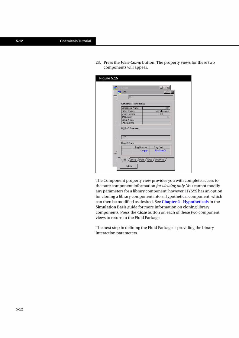
23. Press the View Comp button. The property views for these two components will appear.
The Component property view provides you with complete access to the pure component information for viewing only. You cannot modify any parameters for a library component; however, HYSYS has an option for cloning a library component into a Hypothetical component, which can then be modified as desired. See Chapter 2 - Hypotheticals in the Simulation Basis guide for more information on cloning library components. Press the Close button on each of these two component views to return to the Fluid Package.
The next step in defining the Fluid Package is providing the binary interaction parameters.
Figure 5.15
Chemicals Tutorial 5-13
5-13
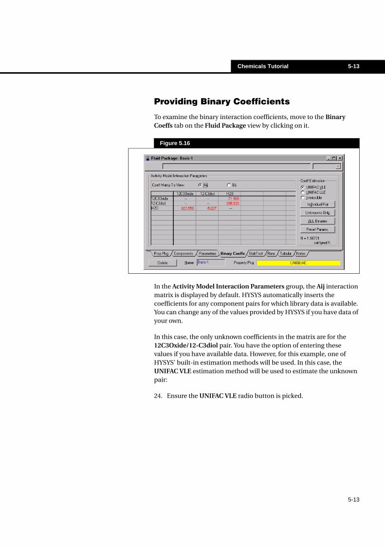
Providing Binary Coefficients
To examine the binary interaction coefficients, move to the Binary Coeffs tab on the Fluid Package view by clicking on it.
In the Activity Model Interaction Parameters group, the Aij interaction matrix is displayed by default. HYSYS automatically inserts the coefficients for any component pairs for which library data is available. You can change any of the values provided by HYSYS if you have data of your own.
In this case, the only unknown coefficients in the matrix are for the 12C3Oxide/12-C3diol pair. You have the option of entering these values if you have available data. However, for this example, one of HYSYS' built-in estimation methods will be used. In this case, the UNIFAC VLE estimation method will be used to estimate the unknown pair:
24. Ensure the UNIFAC VLE radio button is picked.
Figure 5.16
5-14 Chemicals Tutorial
5-14
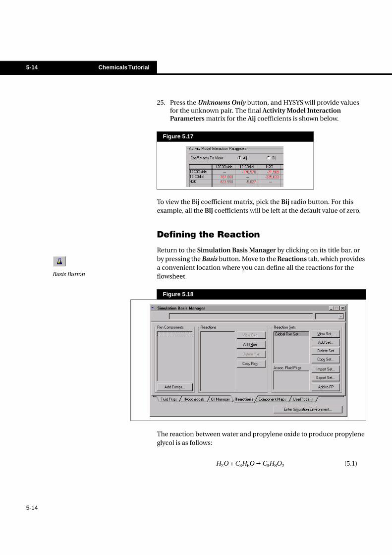
25. Press the Unknowns Only button, and HYSYS will provide values for the unknown pair. The final Activity Model Interaction Parameters matrix for the Aij coefficients is shown below.
To view the Bij coefficient matrix, pick the Bij radio button. For this example, all the Bij coefficients will be left at the default value of zero.
Defining the Reaction
Return to the Simulation Basis Manager by clicking on its title bar, or by pressing the Basis button. Move to the Reactions tab, which provides a convenient location where you can define all the reactions for the flowsheet.
The reaction between water and propylene oxide to produce propylene glycol is as follows:
Figure 5.17
Figure 5.18
Basis Button
H2O + C3H6O � C3H8O2 (5.1)
Chemicals Tutorial 5-15
5-15
Selecting the Reaction Components
The first step in defining the reaction is choosing the components that will be participating in the reaction. In this Tutorial, all the components which were selected in the Fluid Package are also participating in the reaction, so the easiest way to add the reaction components is to simply add all of the Fluid Package components.
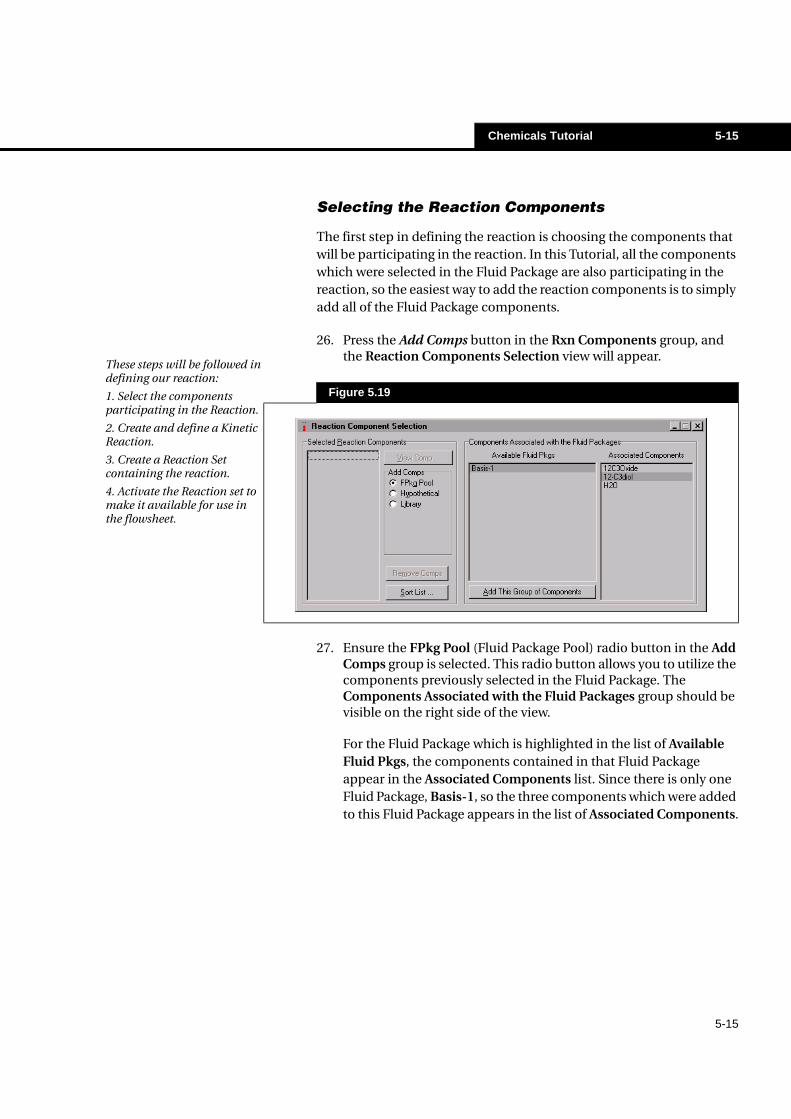
26. Press the Add Comps button in the Rxn Components group, and the Reaction Components Selection view will appear.
27. Ensure the FPkg Pool (Fluid Package Pool) radio button in the Add Comps group is selected. This radio button allows you to utilize the components previously selected in the Fluid Package. The Components Associated with the Fluid Packages group should be visible on the right side of the view.
For the Fluid Package which is highlighted in the list of Available Fluid Pkgs, the components contained in that Fluid Package appear in the Associated Components list. Since there is only one Fluid Package, Basis-1, so the three components which were added to this Fluid Package appears in the list of Associated Components.
Figure 5.19
These steps will be followed in defining our reaction:
1. Select the components participating in the Reaction.
2. Create and define a Kinetic Reaction.
3. Create a Reaction Set containing the reaction.
4. Activate the Reaction set to make it available for use in the flowsheet.
5-16 Chemicals Tutorial
5-16
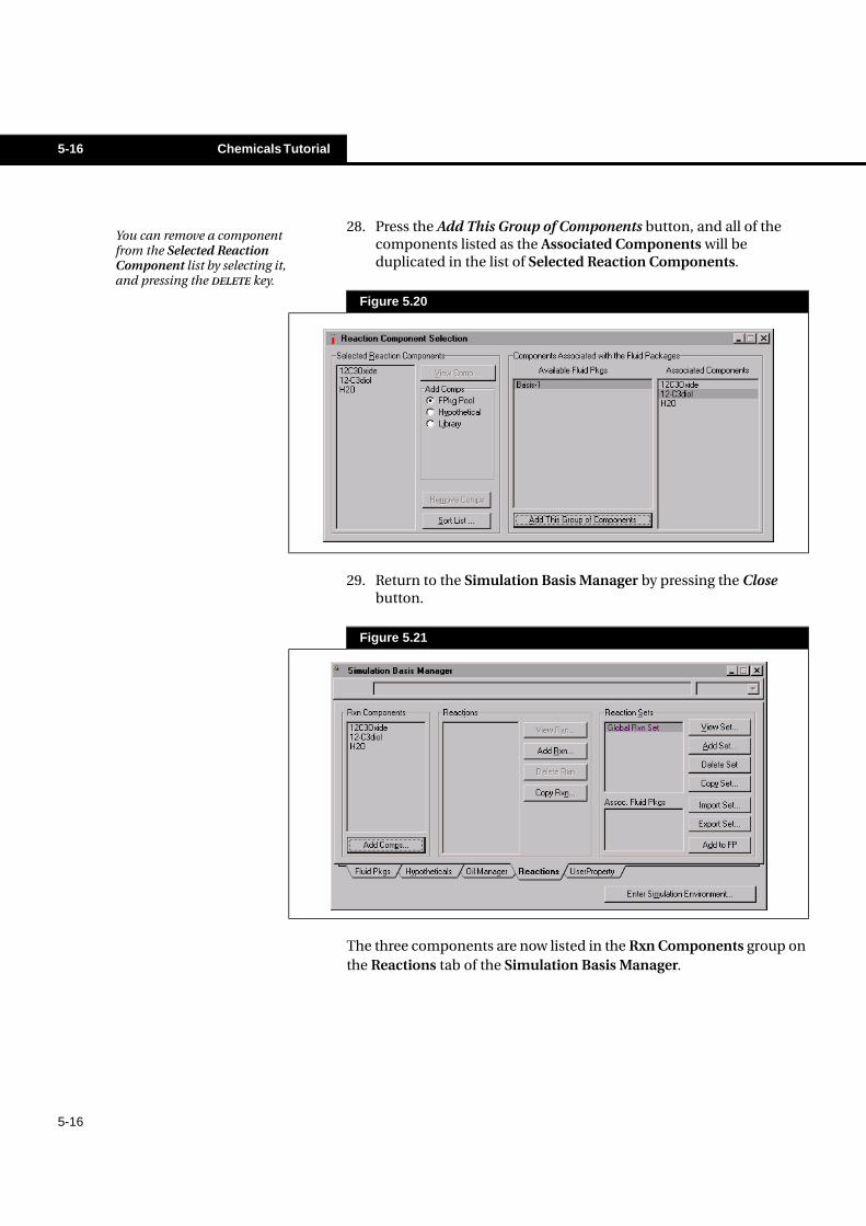
28. Press the Add This Group of Components button, and all of the components listed as the Associated Components will be duplicated in the list of Selected Reaction Components.
29. Return to the Simulation Basis Manager by pressing the Close button.
The three components are now listed in the Rxn Components group on the Reactions tab of the Simulation Basis Manager.
Figure 5.20
Figure 5.21
You can remove a component from the Selected Reaction Component list by selecting it, and pressing the DELETE key.
Chemicals Tutorial 5-17
5-17
Creating the Reaction
Now that the reaction components have been chosen, the next task is to create the reaction:
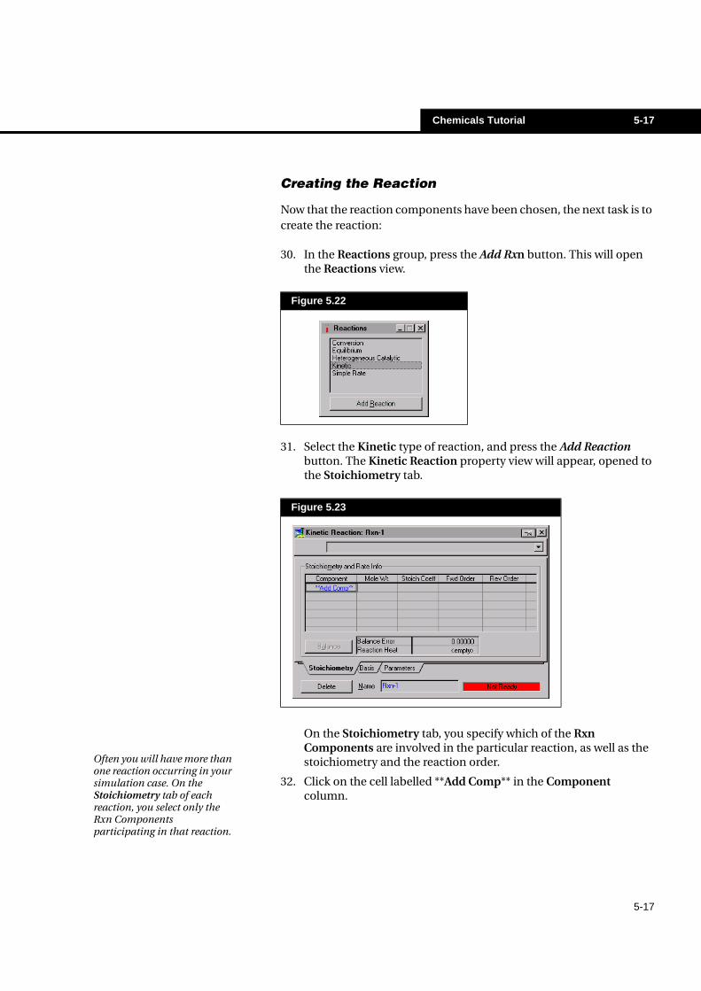
30. In the Reactions group, press the Add Rxn button. This will open the Reactions view.
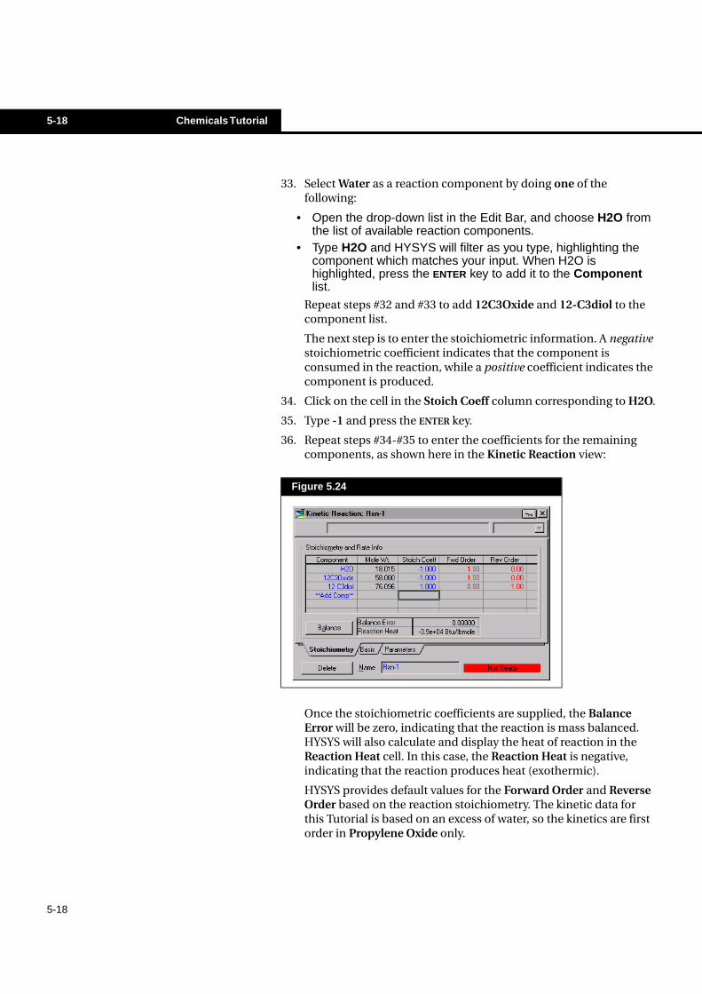
31. Select the Kinetic type of reaction, and press the Add Reaction button. The Kinetic Reaction property view will appear, opened to the Stoichiometry tab.
On the Stoichiometry tab, you specify which of the Rxn Components are involved in the particular reaction, as well as the stoichiometry and the reaction order.
32. Click on the cell labelled **Add Comp** in the Component column.
Figure 5.22
Figure 5.23
Often you will have more than one reaction occurring in your simulation case. On the Stoichiometry tab of each reaction, you select only the Rxn Components participating in that reaction.
5-18 Chemicals Tutorial
5-18
33. Select Water as a reaction component by doing one of the following:
• Open the drop-down list in the Edit Bar, and choose H2O fromthe list of available reaction components.
• Type H2O and HYSYS will filter as you type, highlighting thecomponent which matches your input. When H2O ishighlighted, press the ENTER key to add it to the Componentlist.
Repeat steps #32 and #33 to add 12C3Oxide and 12-C3diol to the component list.
The next step is to enter the stoichiometric information. A negative stoichiometric coefficient indicates that the component is consumed in the reaction, while a positive coefficient indicates the component is produced.
34. Click on the cell in the Stoich Coeff column corresponding to H2O.
35. Type -1 and press the ENTER key.
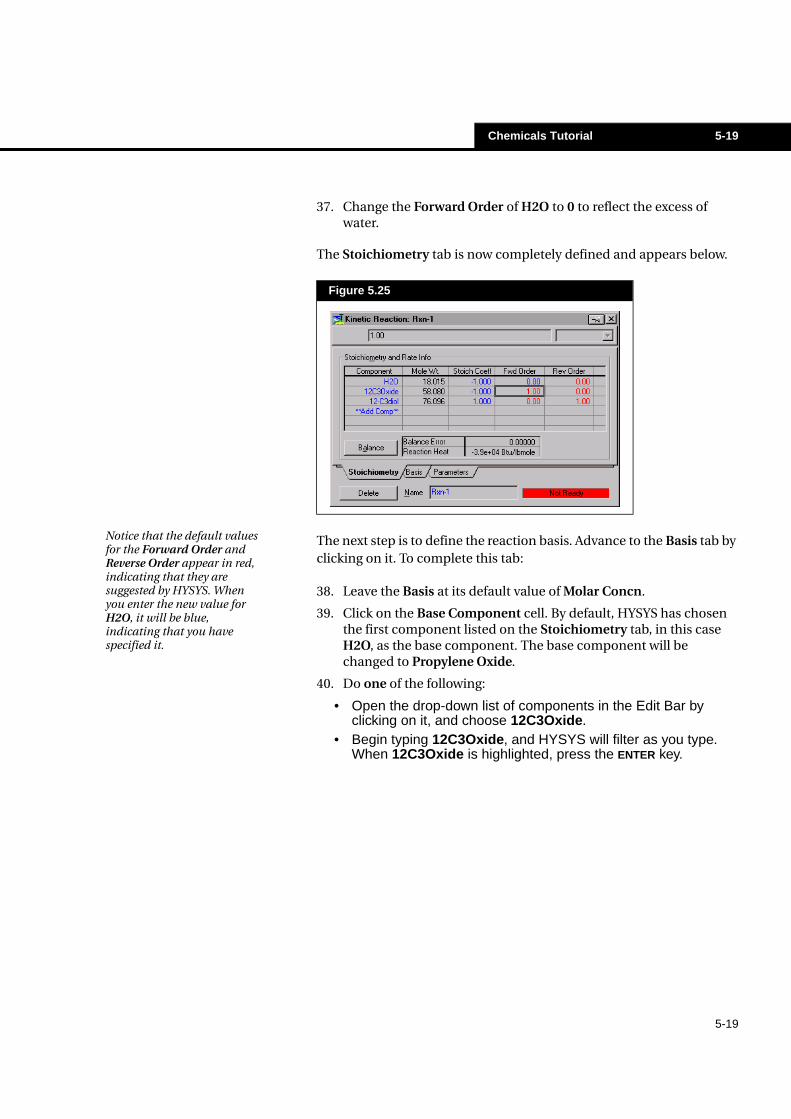
36. Repeat steps #34-#35 to enter the coefficients for the remaining components, as shown here in the Kinetic Reaction view:
Once the stoichiometric coefficients are supplied, the Balance Error will be zero, indicating that the reaction is mass balanced. HYSYS will also calculate and display the heat of reaction in the Reaction Heat cell. In this case, the Reaction Heat is negative, indicating that the reaction produces heat (exothermic).
HYSYS provides default values for the Forward Order and Reverse Order based on the reaction stoichiometry. The kinetic data for this Tutorial is based on an excess of water, so the kinetics are first order in Propylene Oxide only.
Figure 5.24
Chemicals Tutorial 5-19
5-19
37. Change the Forward Order of H2O to 0 to reflect the excess of water.
The Stoichiometry tab is now completely defined and appears below.
The next step is to define the reaction basis. Advance to the Basis tab by clicking on it. To complete this tab:
38. Leave the Basis at its default value of Molar Concn.
39. Click on the Base Component cell. By default, HYSYS has chosen the first component listed on the Stoichiometry tab, in this case H2O, as the base component. The base component will be changed to Propylene Oxide.
40. Do one of the following:
• Open the drop-down list of components in the Edit Bar byclicking on it, and choose 12C3Oxide.
• Begin typing 12C3Oxide, and HYSYS will filter as you type.When 12C3Oxide is highlighted, press the ENTER key.
Figure 5.25
Notice that the default values for the Forward Order and Reverse Order appear in red, indicating that they are suggested by HYSYS. When you enter the new value for H2O, it will be blue, indicating that you have specified it.
5-20 Chemicals Tutorial
5-20
41. Select CombinedLiquid for the Rxn Phase using the drop-down list in the Edit Bar. The completed Basis tab is shown below.
The Min. Temperature, Max. Temperature, Basis Units and Rate Units are acceptable at their default values.
To complete the reaction, advance to the Parameters tab in the Kinetic Reaction property view. On this tab you provide the Arrhenius parameters for the kinetic reaction. In this case, there is no Reverse Reaction occurring, so you only need to supply the Forward Reaction parameters:
42. Enter 1.7e13 for the pre-exponential factor A.
43. Enter 3.24e4 (Btu/lbmole) for the activation energy E.
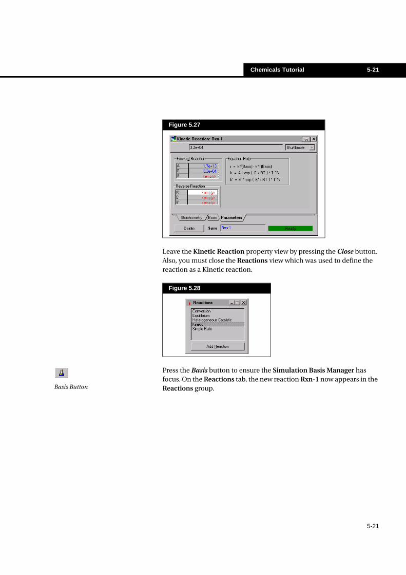
The status indicator at the bottom of the Kinetic Reaction property view changes from Not Ready to Ready, indicating that the reaction is completely defined. The final Parameters tab is shown in Figure 5.27.
Figure 5.26
You can have the same reaction occurring in different phases with different kinetics and have both calculated in the same REACTOR.
Chemicals Tutorial 5-21
5-21
Leave the Kinetic Reaction property view by pressing the Close button. Also, you must close the Reactions view which was used to define the reaction as a Kinetic reaction.
Press the Basis button to ensure the Simulation Basis Manager has focus. On the Reactions tab, the new reaction Rxn-1 now appears in the Reactions group.
Figure 5.27
Figure 5.28
Basis Button
5-22 Chemicals Tutorial
5-22
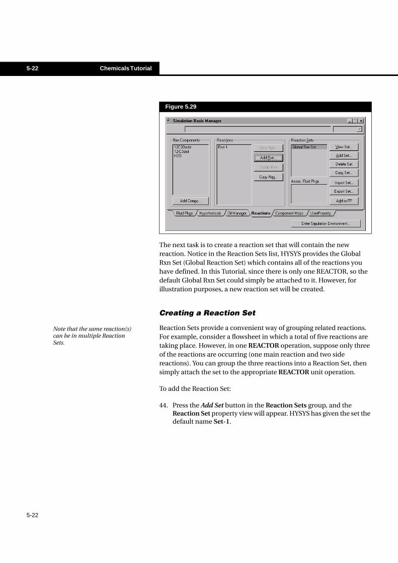
The next task is to create a reaction set that will contain the new reaction. Notice in the Reaction Sets list, HYSYS provides the Global Rxn Set (Global Reaction Set) which contains all of the reactions you have defined. In this Tutorial, since there is only one REACTOR, so the default Global Rxn Set could simply be attached to it. However, for illustration purposes, a new reaction set will be created.
Creating a Reaction Set
Reaction Sets provide a convenient way of grouping related reactions. For example, consider a flowsheet in which a total of five reactions are taking place. However, in one REACTOR operation, suppose only three of the reactions are occurring (one main reaction and two side reactions). You can group the three reactions into a Reaction Set, then simply attach the set to the appropriate REACTOR unit operation.
To add the Reaction Set:
44. Press the Add Set button in the Reaction Sets group, and the Reaction Set property view will appear. HYSYS has given the set the default name Set-1.
Figure 5.29
Note that the same reaction(s) can be in multiple Reaction Sets.
Chemicals Tutorial 5-23
5-23
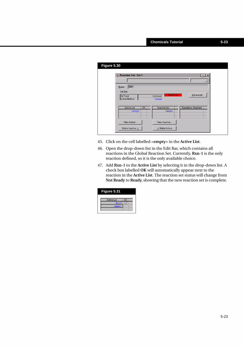
45. Click on the cell labelled <empty> in the Active List.
46. Open the drop-down list in the Edit Bar, which contains all reactions in the Global Reaction Set. Currently, Rxn-1 is the only reaction defined, so it is the only available choice.
47. Add Rxn-1 to the Active List by selecting it in the drop-down list. A check box labelled OK will automatically appear next to the reaction in the Active List. The reaction set status will change from Not Ready to Ready, showing that the new reaction set is complete.
Figure 5.30
Figure 5.31
5-24 Chemicals Tutorial
5-24
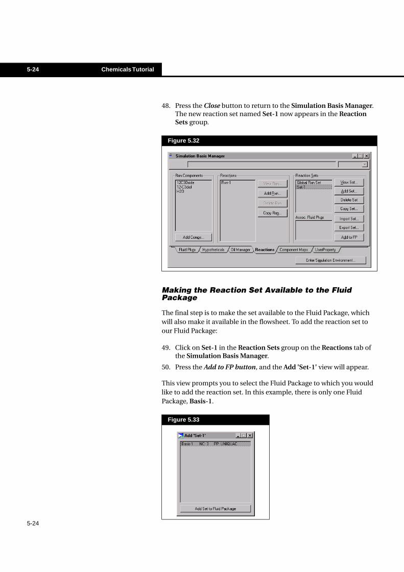
48. Press the Close button to return to the Simulation Basis Manager. The new reaction set named Set-1 now appears in the Reaction Sets group.
Making the Reaction Set Available to the Fluid Package
The final step is to make the set available to the Fluid Package, which will also make it available in the flowsheet. To add the reaction set to our Fluid Package:
49. Click on Set-1 in the Reaction Sets group on the Reactions tab of the Simulation Basis Manager.
50. Press the Add to FP button, and the Add 'Set-1' view will appear.
This view prompts you to select the Fluid Package to which you would like to add the reaction set. In this example, there is only one Fluid Package, Basis-1.
Figure 5.32
Figure 5.33
Chemicals Tutorial 5-25
5-25
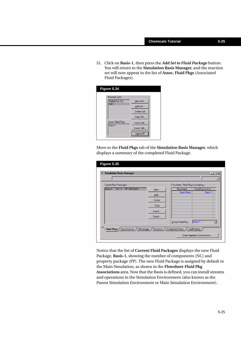
51. Click on Basis-1, then press the Add Set to Fluid Package button. You will return to the Simulation Basis Manager, and the reaction set will now appear in the list of Assoc. Fluid Pkgs (Associated Fluid Packages).
Move to the Fluid Pkgs tab of the Simulation Basis Manager, which displays a summary of the completed Fluid Package.
Notice that the list of Current Fluid Packages displays the new Fluid Package, Basis-1, showing the number of components (NC) and property package (PP). The new Fluid Package is assigned by default to the Main Simulation, as shown in the Flowsheet-Fluid Pkg Associations area. Now that the Basis is defined, you can install streams and operations in the Simulation Environment (also known as the Parent Simulation Environment or Main Simulation Environment).
Figure 5.34
Figure 5.35
5-26 Chemicals Tutorial
5-26
To enter this environment and leave the Basis environment, do one of the following:
• Press the Enter Simulation Environment button on theSimulation Basis Manager.
• Press the Enter Simulation Environment button in the buttonbar.
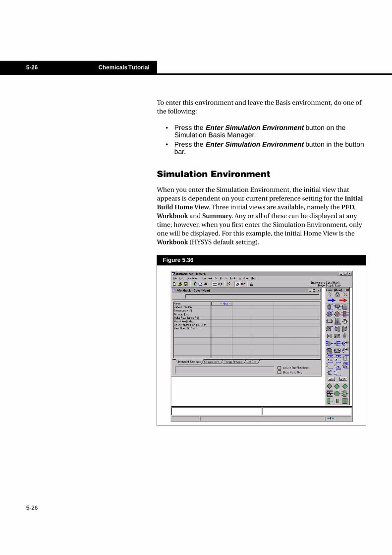
Simulation Environment
When you enter the Simulation Environment, the initial view that appears is dependent on your current preference setting for the Initial Build Home View. Three initial views are available, namely the PFD, Workbook and Summary. Any or all of these can be displayed at any time; however, when you first enter the Simulation Environment, only one will be displayed. For this example, the initial Home View is the Workbook (HYSYS default setting).
Figure 5.36
Chemicals Tutorial 5-27
5-27
You will notice several things about the Main Simulation Environment. In the upper right corner, the Environment has changed from Basis to Case (Main). A number of new items are now available on the Menu and Button Bar, and the Workbook and Object Palette are open on the Desktop. These two latter objects are described below.
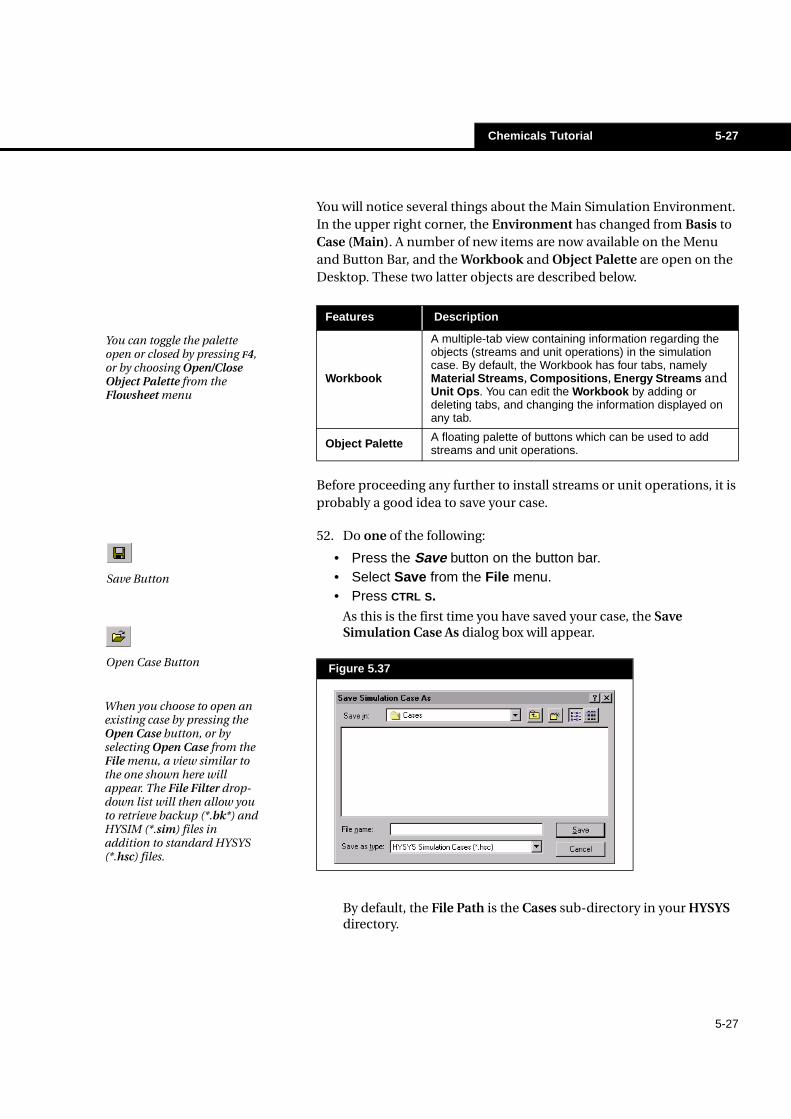
Before proceeding any further to install streams or unit operations, it is probably a good idea to save your case.
52. Do one of the following:
• Press the Save button on the button bar.• Select Save from the File menu.• Press CTRL S.
As this is the first time you have saved your case, the Save Simulation Case As dialog box will appear.
By default, the File Path is the Cases sub-directory in your HYSYS directory.
Features Description
Workbook
A multiple-tab view containing information regarding theobjects (streams and unit operations) in the simulationcase. By default, the Workbook has four tabs, namelyMaterial Streams, Compositions, Energy Streams andUnit Ops. You can edit the Workbook by adding ordeleting tabs, and changing the information displayed onany tab.
Object Palette A floating palette of buttons which can be used to addstreams and unit operations.
You can toggle the palette open or closed by pressing F4, or by choosing Open/Close Object Palette from the Flowsheet menu
Figure 5.37
Save Button
Open Case Button
When you choose to open an existing case by pressing the Open Case button, or by selecting Open Case from the File menu, a view similar to the one shown here will appear. The File Filter drop-down list will then allow you to retrieve backup (*.bk*) and HYSIM (*.sim) files in addition to standard HYSYS (*.hsc) files.
5-28 Chemicals Tutorial
5-28
53. In the File Name cell type a name for the case, for example GLYCOL. You do not have to enter the .hsc extension; HYSYS will automatically add it for you.
54. Once you have entered a file name, press the ENTER key or the OK button. HYSYS will now save the case under the name you have given it when you Save in the future. The Save As dialog box will not appear again unless you choose to give it a new name using the Save As command.
Before any streams or operations are installed, the simulated process will be summarized.
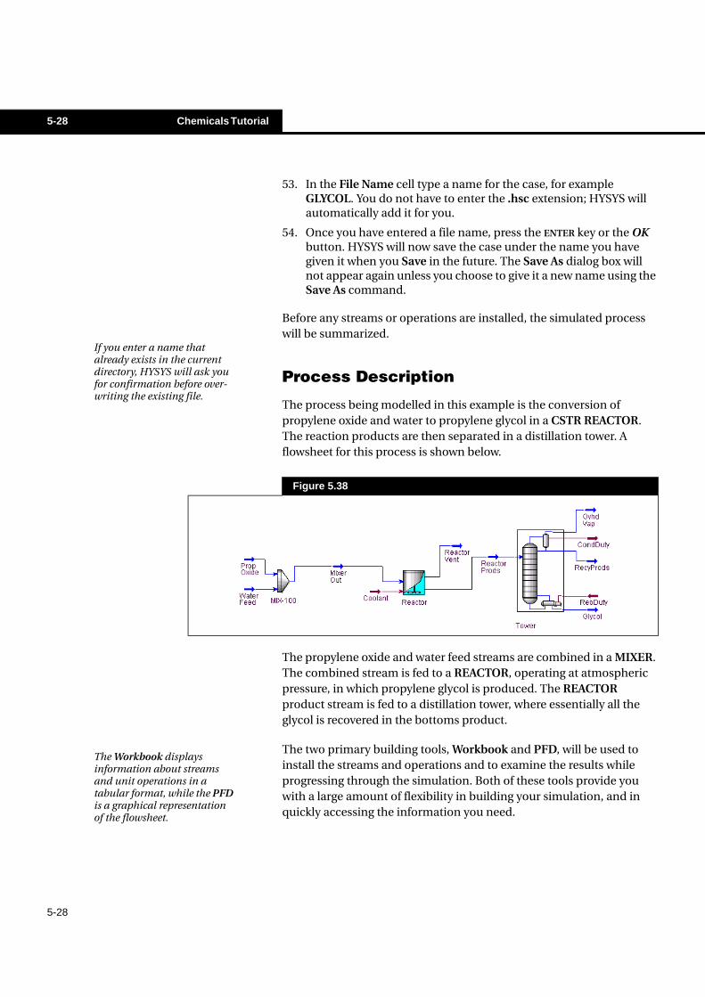
Process Description
The process being modelled in this example is the conversion of propylene oxide and water to propylene glycol in a CSTR REACTOR. The reaction products are then separated in a distillation tower. A flowsheet for this process is shown below.
The propylene oxide and water feed streams are combined in a MIXER. The combined stream is fed to a REACTOR, operating at atmospheric pressure, in which propylene glycol is produced. The REACTOR product stream is fed to a distillation tower, where essentially all the glycol is recovered in the bottoms product.
The two primary building tools, Workbook and PFD, will be used to install the streams and operations and to examine the results while progressing through the simulation. Both of these tools provide you with a large amount of flexibility in building your simulation, and in quickly accessing the information you need.
If you enter a name that already exists in the current directory, HYSYS will ask you for confirmation before over-writing the existing file.
Figure 5.38
The Workbook displays information about streams and unit operations in a tabular format, while the PFD is a graphical representation of the flowsheet.
Chemicals Tutorial 5-29
5-29
The Workbook will be used to build the first part of the flowsheet, including the feed streams and the mixer. The PFD will then be used to install the reactor, and a special sequence of views called the Input Expert to install the distillation column.
Using the Workbook
Press the Workbook button on the button bar to ensure the Workbook has focus.
Installing the Feed Streams
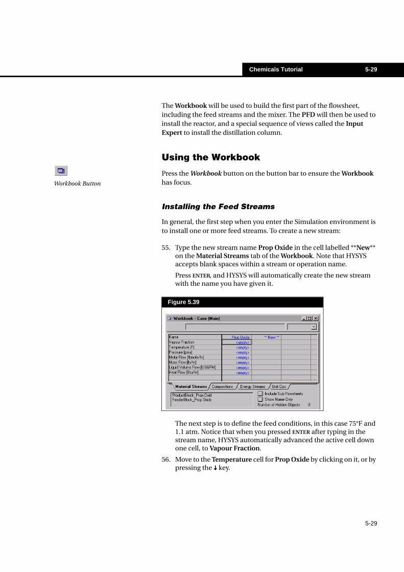
In general, the first step when you enter the Simulation environment is to install one or more feed streams. To create a new stream:
55. Type the new stream name Prop Oxide in the cell labelled **New** on the Material Streams tab of the Workbook. Note that HYSYS accepts blank spaces within a stream or operation name.
Press ENTER, and HYSYS will automatically create the new stream with the name you have given it.
The next step is to define the feed conditions, in this case 75°F and 1.1 atm. Notice that when you pressed ENTER after typing in the stream name, HYSYS automatically advanced the active cell down one cell, to Vapour Fraction.
56. Move to the Temperature cell for Prop Oxide by clicking on it, or by pressing the ���� key.
Figure 5.39
Workbook Button
5-30 Chemicals Tutorial
5-30
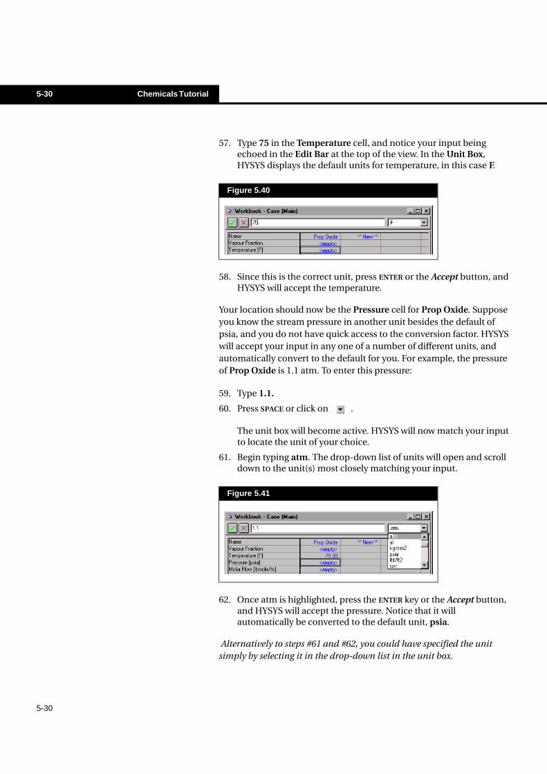
57. Type 75 in the Temperature cell, and notice your input being echoed in the Edit Bar at the top of the view. In the Unit Box, HYSYS displays the default units for temperature, in this case F.
58. Since this is the correct unit, press ENTER or the Accept button, and HYSYS will accept the temperature.
Your location should now be the Pressure cell for Prop Oxide. Suppose you know the stream pressure in another unit besides the default of psia, and you do not have quick access to the conversion factor. HYSYS will accept your input in any one of a number of different units, and automatically convert to the default for you. For example, the pressure of Prop Oxide is 1.1 atm. To enter this pressure:
59. Type 1.1.
60. Press SPACE or click on .
The unit box will become active. HYSYS will now match your input to locate the unit of your choice.
61. Begin typing atm. The drop-down list of units will open and scroll down to the unit(s) most closely matching your input.
62. Once atm is highlighted, press the ENTER key or the Accept button, and HYSYS will accept the pressure. Notice that it will automatically be converted to the default unit, psia.
Alternatively to steps #61 and #62, you could have specified the unit simply by selecting it in the drop-down list in the unit box.
Figure 5.40
Figure 5.41
Chemicals Tutorial 5-31
5-31
The Molar Flow cell for Prop Oxide should now be your active Workbook location. The next step is to enter the stream flow rate, 150 lbmole/hr. Since the default Molar Flow unit for our unit set is lbmole/hr., simply type 150 followed by ENTER.
Providing Compositional Input
Now that the stream conditions have been specified, the next step is to input the composition:
63. Move to the Compositions tab in the Workbook by clicking on it, or by pressing CTRL SHIFT N.
The components are listed in Mole Fraction by default.
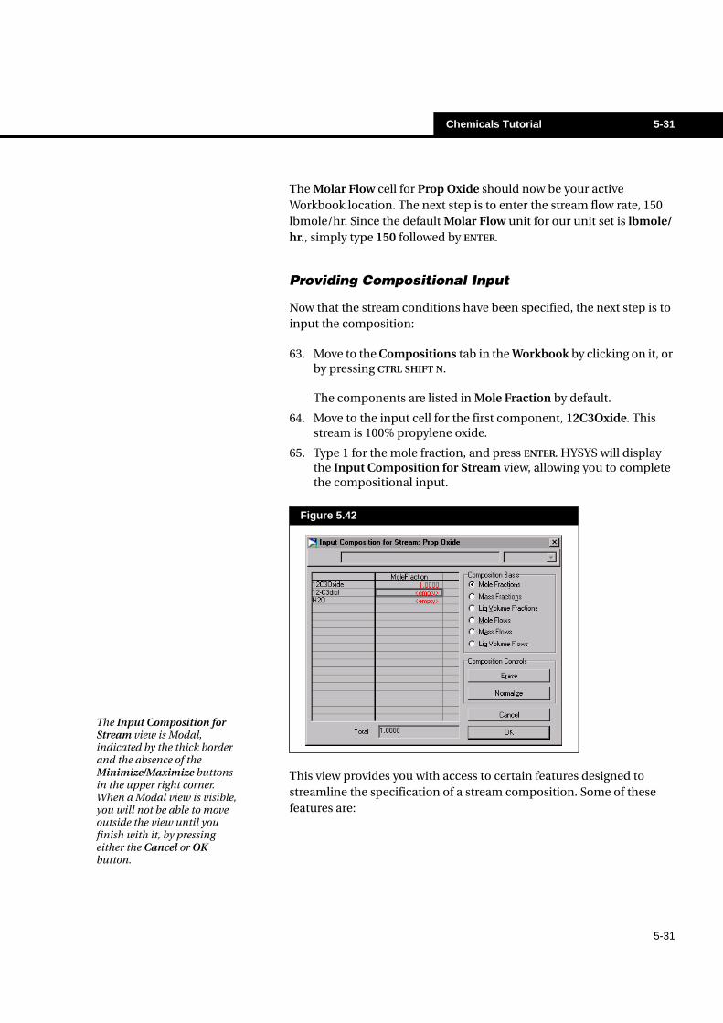
64. Move to the input cell for the first component, 12C3Oxide. This stream is 100% propylene oxide.
65. Type 1 for the mole fraction, and press ENTER. HYSYS will display the Input Composition for Stream view, allowing you to complete the compositional input.
This view provides you with access to certain features designed to streamline the specification of a stream composition. Some of these features are:
Figure 5.42
The Input Composition for Stream view is Modal, indicated by the thick border and the absence of the Minimize/Maximize buttons in the upper right corner. When a Modal view is visible, you will not be able to move outside the view until you finish with it, by pressing either the Cancel or OK button.
5-32 Chemicals Tutorial
5-32
In this case, 12C3Oxide is the only component in the stream.
Features Description
CompositionalBasis RadioButtons
You can input the stream composition in some fractionalbasis other than Mole Fraction, or by component flows, bypicking the appropriate radio button before providing yourinput.
Normalizing
The Normalizing feature is useful when you know therelative ratios of components; for example, 2 parts N2, 2parts CO2, 120 parts C1, etc. Rather than manuallyconverting these ratios to fractions summing to one,simply enter the individual numbers of parts and press theNormalize button. HYSYS will compute the individualfractions totalling 1.0.
Normalizing is also useful when you have a streamconsisting of only a few components. Instead of specifyingzero fractions (or flows) for the other components, simplyenter the fractions (or the actual flows) for the non-zerocomponents, leaving the others <empty>. Then press theNormalize button, and HYSYS will force the othercomponent fractions to zero.
Calculationstatus/colour
As you input the composition, the component fractions (orflows) initially appear in red, indicating the finalcomposition is unknown. These values will become bluewhen the stream composition has been calculated. Threescenarios will result in the stream composition beingcalculated:
• Input the fractions of all components, including anyzero components, such that their total is exactly1.0000. Then press the OK button.
• Input the fractions (totalling 1.000), flows or relativenumber of parts of all non-zero components. Thenpress the Normalize button then the OK button.
• Input the flows or relative number of parts of allcomponents, including any zero components, thenpress the OK button.
Note that these are the default colours; yours may appear differently depending on your settings on the Colours page of the Session Preferences.
Chemicals Tutorial 5-33
5-33
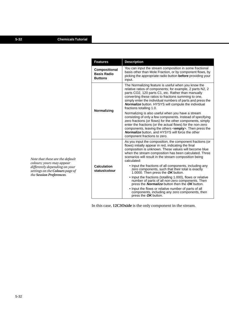
66. Press the Normalize button to force the other values to zero. The composition is now defined.
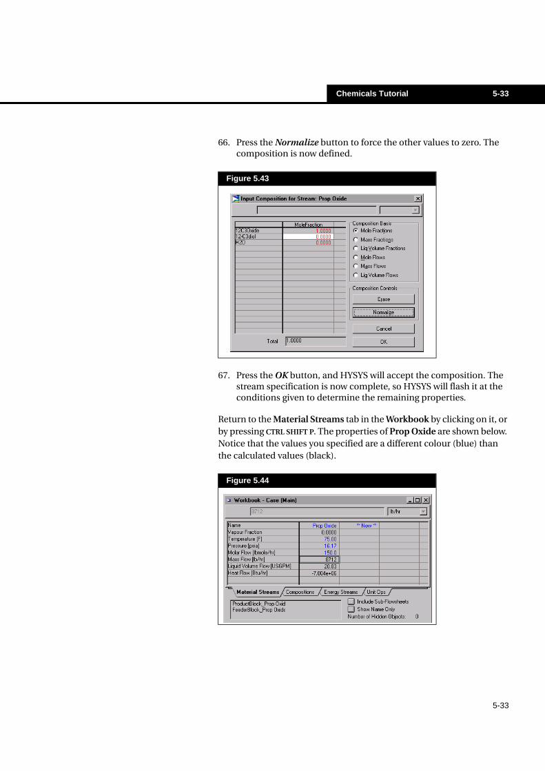
67. Press the OK button, and HYSYS will accept the composition. The stream specification is now complete, so HYSYS will flash it at the conditions given to determine the remaining properties.
Return to the Material Streams tab in the Workbook by clicking on it, or by pressing CTRL SHIFT P. The properties of Prop Oxide are shown below. Notice that the values you specified are a different colour (blue) than the calculated values (black).
Figure 5.43
Figure 5.44
5-34 Chemicals Tutorial
5-34
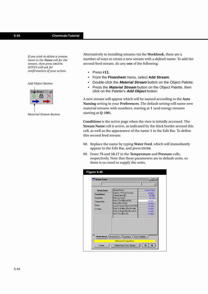
Alternatively to installing streams via the Workbook, there are a number of ways to create a new stream with a default name. To add the second feed stream, do any one of the following:
• Press F11.• From the Flowsheet menu, select Add Stream.• Double-click the Material Stream button on the Object Palette.• Press the Material Stream button on the Object Palette, then
click on the Palette's Add Object button.
A new stream will appear which will be named according to the Auto Naming setting in your Preferences. The default setting will name new material streams with numbers, starting at 1 (and energy streams starting at Q-100).
Conditions is the active page when the view is initially accessed. The Stream Name cell is active, as indicated by the thick border around this cell, as well as the appearance of the name 1 in the Edit Bar. To define this second feed stream:
68. Replace the name by typing Water Feed, which will immediately appear in the Edit Bar, and press ENTER.
69. Enter 75 and 16.17 in the Temperature and Pressure cells, respectively. Note that these parameters are in default units, so there is no need to supply the units.
Figure 5.45
If you wish to delete a stream, move to the Name cell for the stream, then press DELETE. HYSYS will ask for confirmation of your action.
Add Object Button
Material Stream Button
Chemicals Tutorial 5-35
5-35
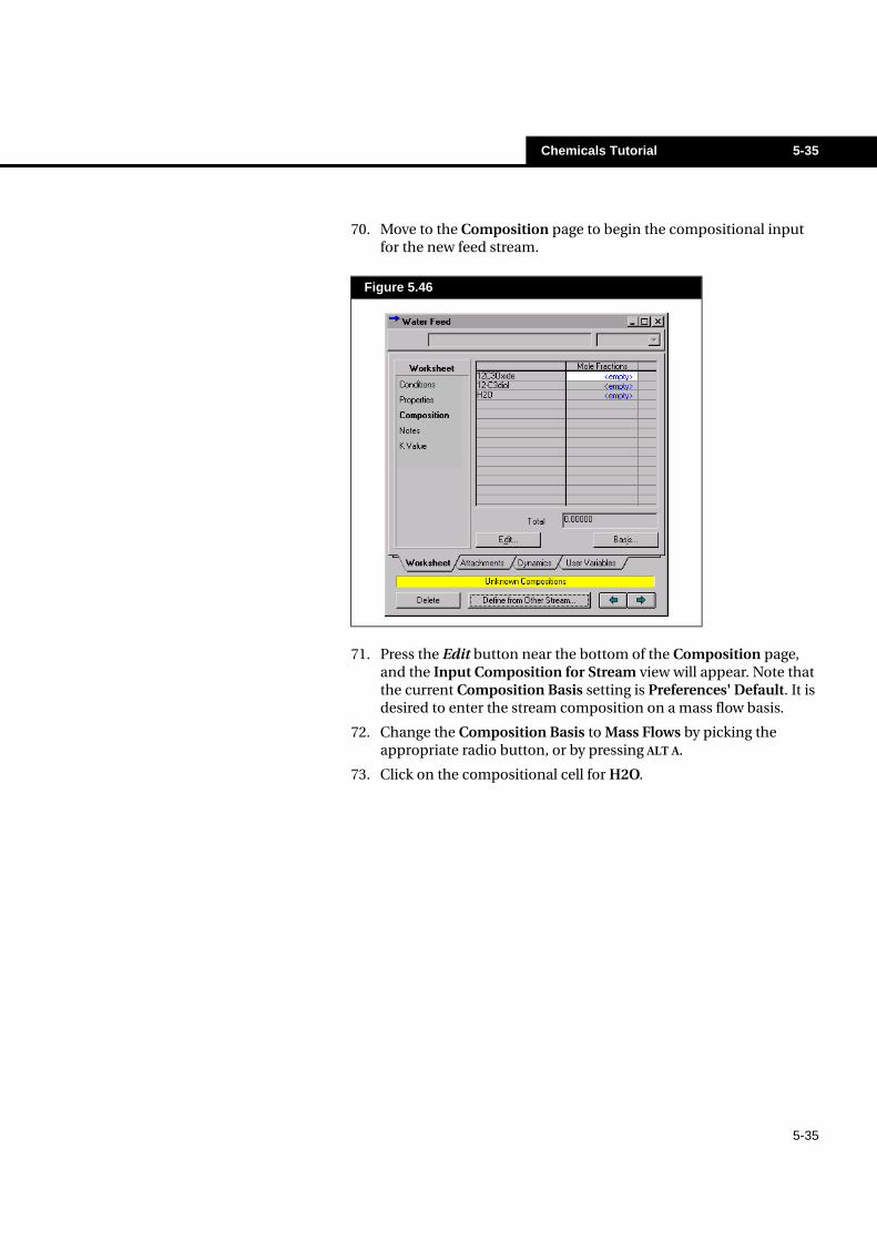
70. Move to the Composition page to begin the compositional input for the new feed stream.
71. Press the Edit button near the bottom of the Composition page, and the Input Composition for Stream view will appear. Note that the current Composition Basis setting is Preferences' Default. It is desired to enter the stream composition on a mass flow basis.
72. Change the Composition Basis to Mass Flows by picking the appropriate radio button, or by pressing ALT A.
73. Click on the compositional cell for H2O.
Figure 5.46
5-36 Chemicals Tutorial
5-36
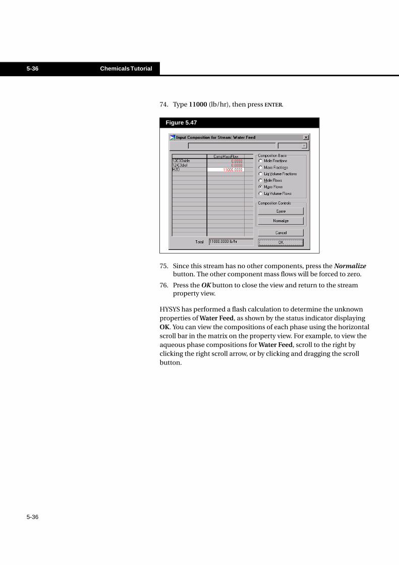
74. Type 11000 (lb/hr), then press ENTER.
75. Since this stream has no other components, press the Normalize button. The other component mass flows will be forced to zero.
76. Press the OK button to close the view and return to the stream property view.
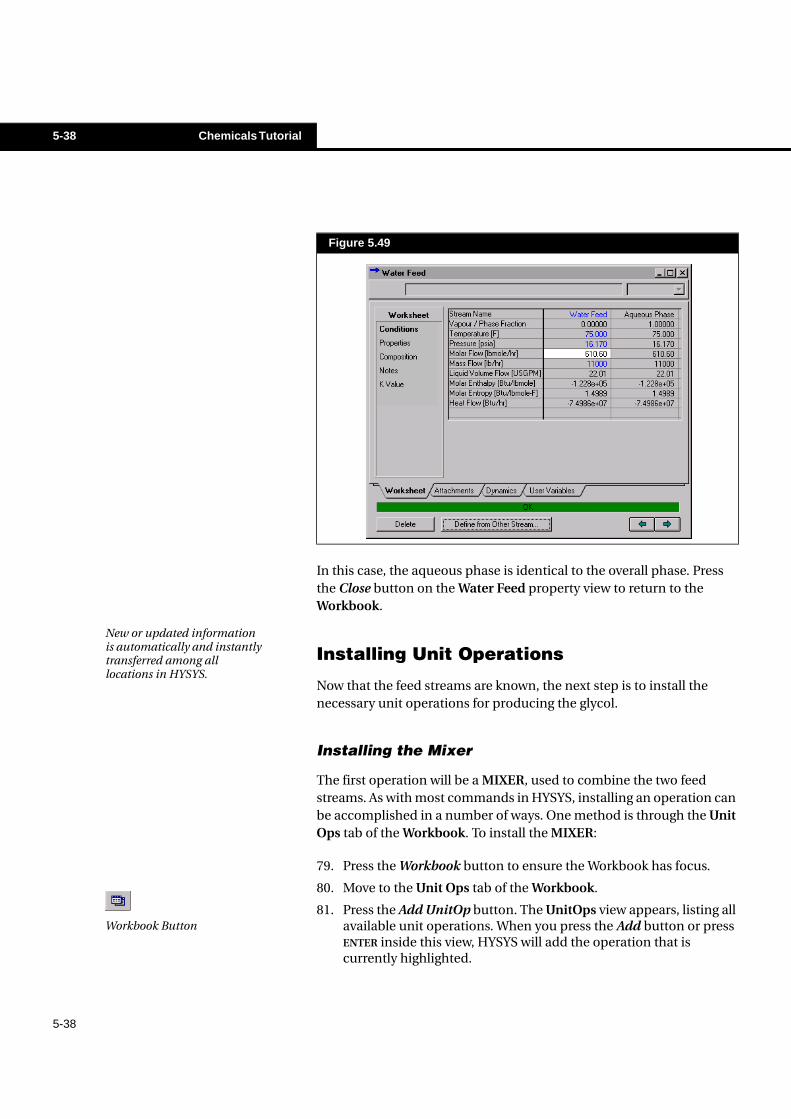
HYSYS has performed a flash calculation to determine the unknown properties of Water Feed, as shown by the status indicator displaying OK. You can view the compositions of each phase using the horizontal scroll bar in the matrix on the property view. For example, to view the aqueous phase compositions for Water Feed, scroll to the right by clicking the right scroll arrow, or by clicking and dragging the scroll button.
Figure 5.47
Chemicals Tutorial 5-37
5-37
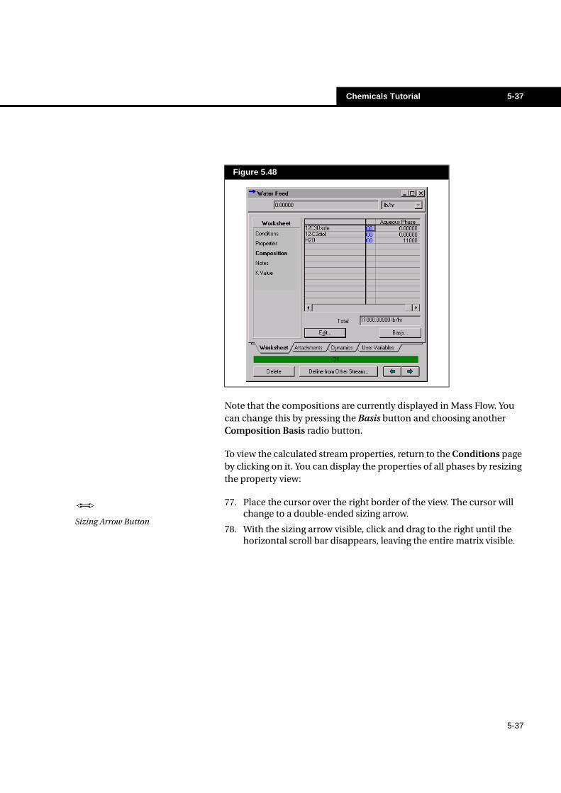
Note that the compositions are currently displayed in Mass Flow. You can change this by pressing the Basis button and choosing another Composition Basis radio button.
To view the calculated stream properties, return to the Conditions page by clicking on it. You can display the properties of all phases by resizing the property view:
77. Place the cursor over the right border of the view. The cursor will change to a double-ended sizing arrow.
78. With the sizing arrow visible, click and drag to the right until the horizontal scroll bar disappears, leaving the entire matrix visible.
Figure 5.48
Sizing Arrow Button
5-38 Chemicals Tutorial
5-38
In this case, the aqueous phase is identical to the overall phase. Press the Close button on the Water Feed property view to return to the Workbook.
Installing Unit Operations
Now that the feed streams are known, the next step is to install the necessary unit operations for producing the glycol.
Installing the Mixer
The first operation will be a MIXER, used to combine the two feed streams. As with most commands in HYSYS, installing an operation can be accomplished in a number of ways. One method is through the Unit Ops tab of the Workbook. To install the MIXER:
79. Press the Workbook button to ensure the Workbook has focus.
80. Move to the Unit Ops tab of the Workbook.
81. Press the Add UnitOp button. The UnitOps view appears, listing all available unit operations. When you press the Add button or press ENTER inside this view, HYSYS will add the operation that is currently highlighted.
Figure 5.49
New or updated information is automatically and instantly transferred among all locations in HYSYS.
Workbook Button
Chemicals Tutorial 5-39
5-39
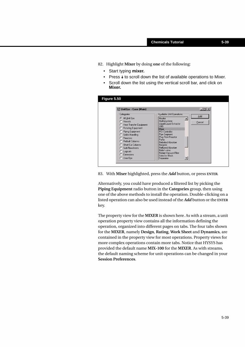
82. Highlight Mixer by doing one of the following:
• Start typing mixer.• Press ���� to scroll down the list of available operations to Mixer.• Scroll down the list using the vertical scroll bar, and click on
Mixer.
83. With Mixer highlighted, press the Add button, or press ENTER.
Alternatively, you could have produced a filtered list by picking the Piping Equipment radio button in the Categories group, then using one of the above methods to install the operation. Double-clicking on a listed operation can also be used instead of the Add button or the ENTER key.
The property view for the MIXER is shown here. As with a stream, a unit operation property view contains all the information defining the operation, organized into different pages on tabs. The four tabs shown for the MIXER, namely Design, Rating, Work Sheet and Dynamics, are contained in the property view for most operations. Property views for more complex operations contain more tabs. Notice that HYSYS has provided the default name MIX-100 for the MIXER. As with streams, the default naming scheme for unit operations can be changed in your Session Preferences.
Figure 5.50
5-40 Chemicals Tutorial
5-40
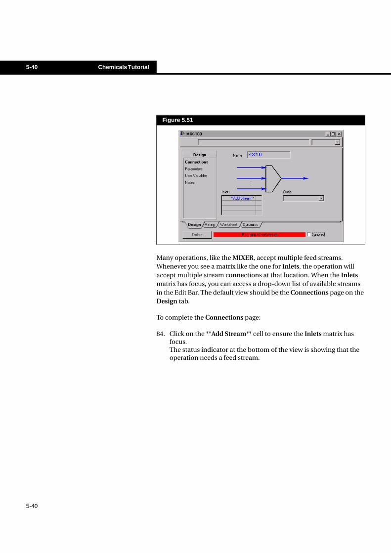
Many operations, like the MIXER, accept multiple feed streams. Whenever you see a matrix like the one for Inlets, the operation will accept multiple stream connections at that location. When the Inlets matrix has focus, you can access a drop-down list of available streams in the Edit Bar. The default view should be the Connections page on the Design tab.
To complete the Connections page:
84. Click on the **Add Stream** cell to ensure the Inlets matrix has focus.The status indicator at the bottom of the view is showing that the operation needs a feed stream.
Figure 5.51
Chemicals Tutorial 5-41
5-41
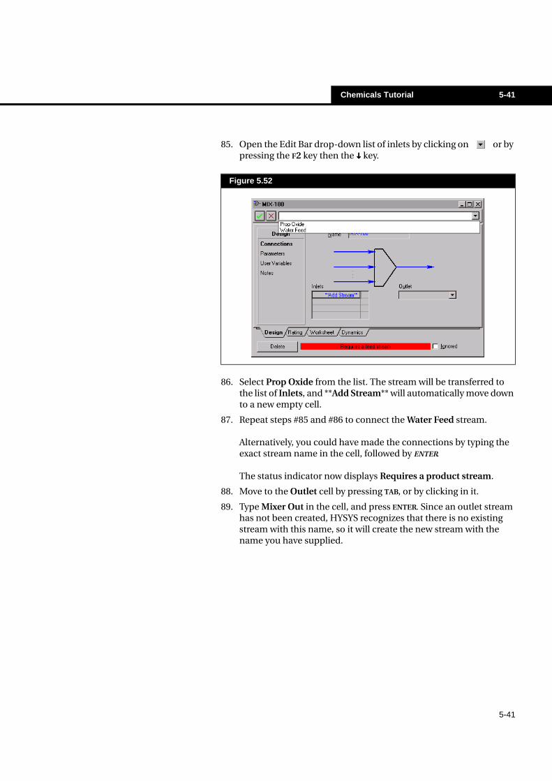
85. Open the Edit Bar drop-down list of inlets by clicking on or by pressing the F2 key then the ���� key.
86. Select Prop Oxide from the list. The stream will be transferred to the list of Inlets, and **Add Stream** will automatically move down to a new empty cell.
87. Repeat steps #85 and #86 to connect the Water Feed stream.
Alternatively, you could have made the connections by typing the exact stream name in the cell, followed by ENTER.
The status indicator now displays Requires a product stream.
88. Move to the Outlet cell by pressing TAB, or by clicking in it.
89. Type Mixer Out in the cell, and press ENTER. Since an outlet stream has not been created, HYSYS recognizes that there is no existing stream with this name, so it will create the new stream with the name you have supplied.
Figure 5.52
5-42 Chemicals Tutorial
5-42
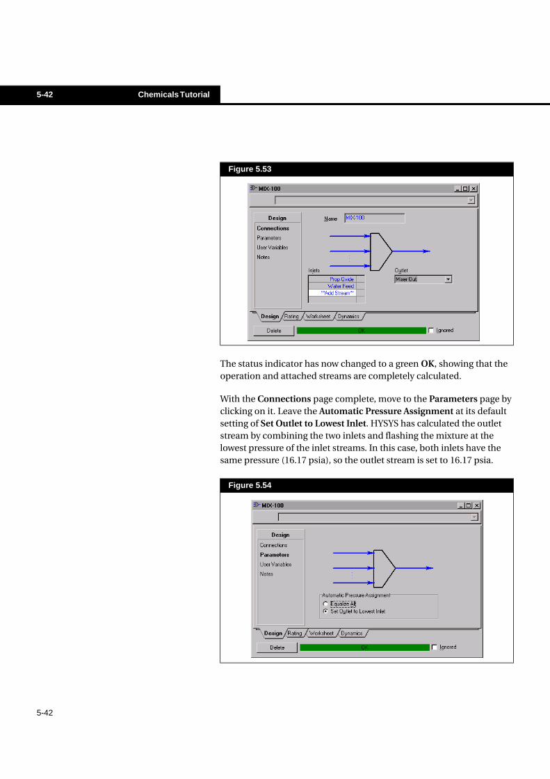
The status indicator has now changed to a green OK, showing that the operation and attached streams are completely calculated.
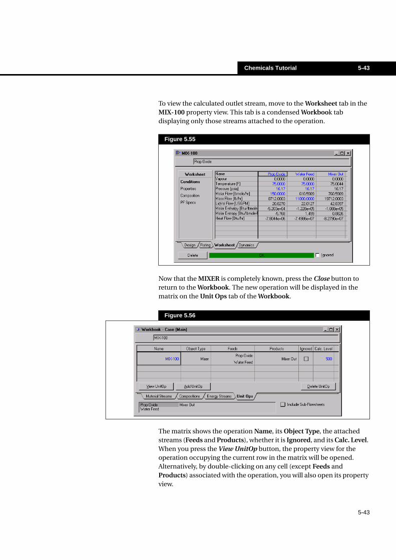
With the Connections page complete, move to the Parameters page by clicking on it. Leave the Automatic Pressure Assignment at its default setting of Set Outlet to Lowest Inlet. HYSYS has calculated the outlet stream by combining the two inlets and flashing the mixture at the lowest pressure of the inlet streams. In this case, both inlets have the same pressure (16.17 psia), so the outlet stream is set to 16.17 psia.
Figure 5.53
Figure 5.54
Chemicals Tutorial 5-43
5-43
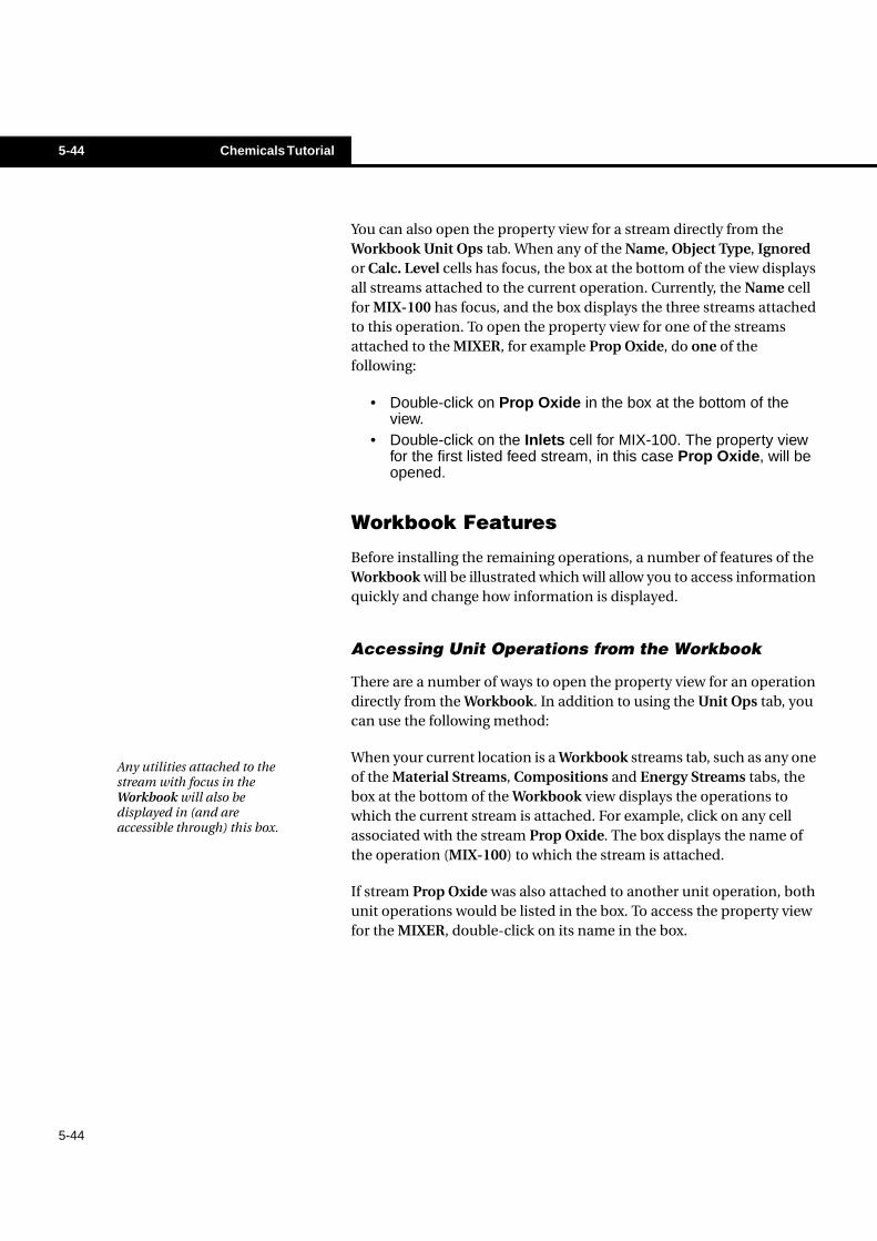
To view the calculated outlet stream, move to the Worksheet tab in the MIX-100 property view. This tab is a condensed Workbook tab displaying only those streams attached to the operation.
Now that the MIXER is completely known, press the Close button to return to the Workbook. The new operation will be displayed in the matrix on the Unit Ops tab of the Workbook.
The matrix shows the operation Name, its Object Type, the attached streams (Feeds and Products), whether it is Ignored, and its Calc. Level. When you press the View UnitOp button, the property view for the operation occupying the current row in the matrix will be opened. Alternatively, by double-clicking on any cell (except Feeds and Products) associated with the operation, you will also open its property view.
Figure 5.55
Figure 5.56
5-44 Chemicals Tutorial
5-44
You can also open the property view for a stream directly from the Workbook Unit Ops tab. When any of the Name, Object Type, Ignored or Calc. Level cells has focus, the box at the bottom of the view displays all streams attached to the current operation. Currently, the Name cell for MIX-100 has focus, and the box displays the three streams attached to this operation. To open the property view for one of the streams attached to the MIXER, for example Prop Oxide, do one of the following:
• Double-click on Prop Oxide in the box at the bottom of theview.
• Double-click on the Inlets cell for MIX-100. The property viewfor the first listed feed stream, in this case Prop Oxide, will beopened.
Workbook Features
Before installing the remaining operations, a number of features of the Workbook will be illustrated which will allow you to access information quickly and change how information is displayed.
Accessing Unit Operations from the Workbook
There are a number of ways to open the property view for an operation directly from the Workbook. In addition to using the Unit Ops tab, you can use the following method:
When your current location is a Workbook streams tab, such as any one of the Material Streams, Compositions and Energy Streams tabs, the box at the bottom of the Workbook view displays the operations to which the current stream is attached. For example, click on any cell associated with the stream Prop Oxide. The box displays the name of the operation (MIX-100) to which the stream is attached.
If stream Prop Oxide was also attached to another unit operation, both unit operations would be listed in the box. To access the property view for the MIXER, double-click on its name in the box.
Any utilities attached to the stream with focus in the Workbook will also be displayed in (and are accessible through) this box.
Chemicals Tutorial 5-45
5-45
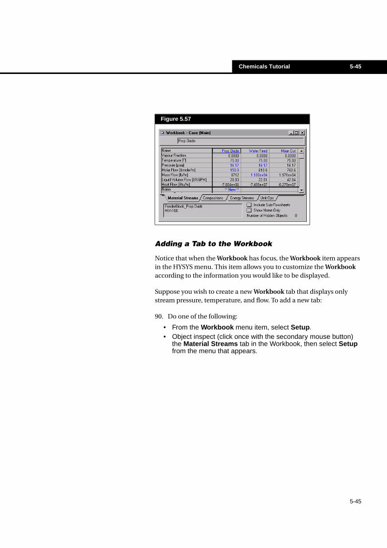
Adding a Tab to the Workbook
Notice that when the Workbook has focus, the Workbook item appears in the HYSYS menu. This item allows you to customize the Workbook according to the information you would like to be displayed.
Suppose you wish to create a new Workbook tab that displays only stream pressure, temperature, and flow. To add a new tab:
90. Do one of the following:
• From the Workbook menu item, select Setup.• Object inspect (click once with the secondary mouse button)
the Material Streams tab in the Workbook, then select Setupfrom the menu that appears.
Figure 5.57
5-46 Chemicals Tutorial
5-46
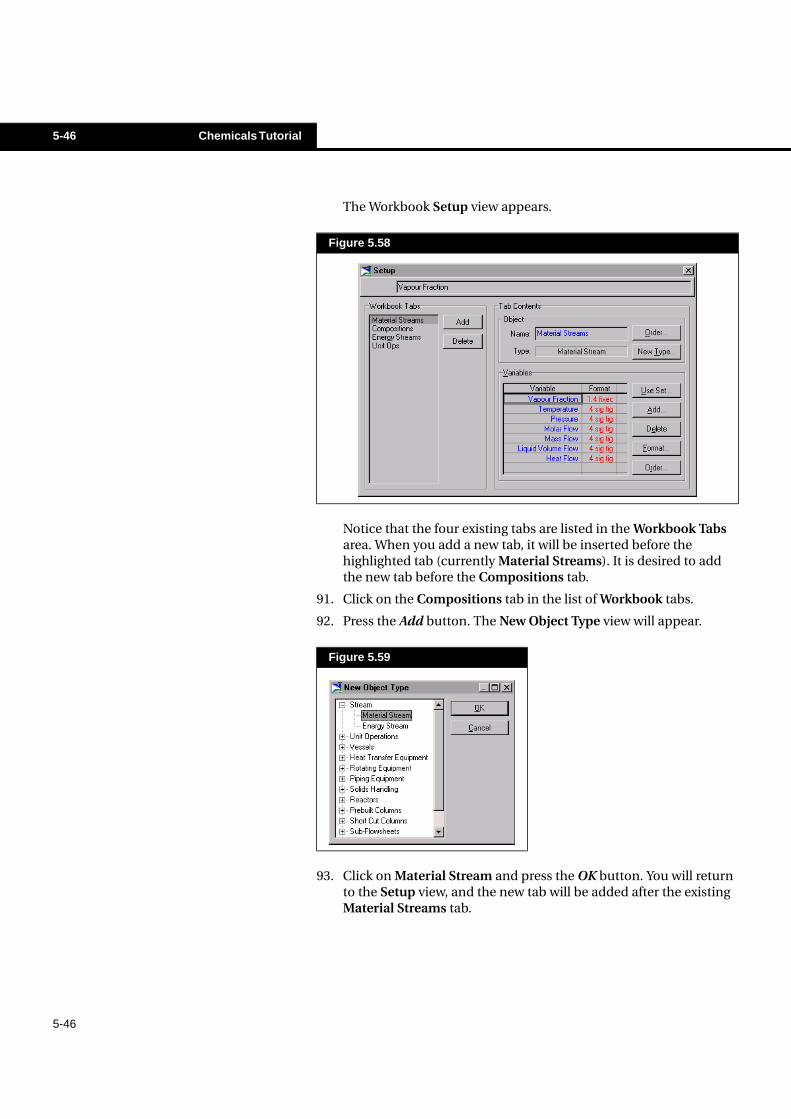
The Workbook Setup view appears.
Notice that the four existing tabs are listed in the Workbook Tabs area. When you add a new tab, it will be inserted before the highlighted tab (currently Material Streams). It is desired to add the new tab before the Compositions tab.
91. Click on the Compositions tab in the list of Workbook tabs.
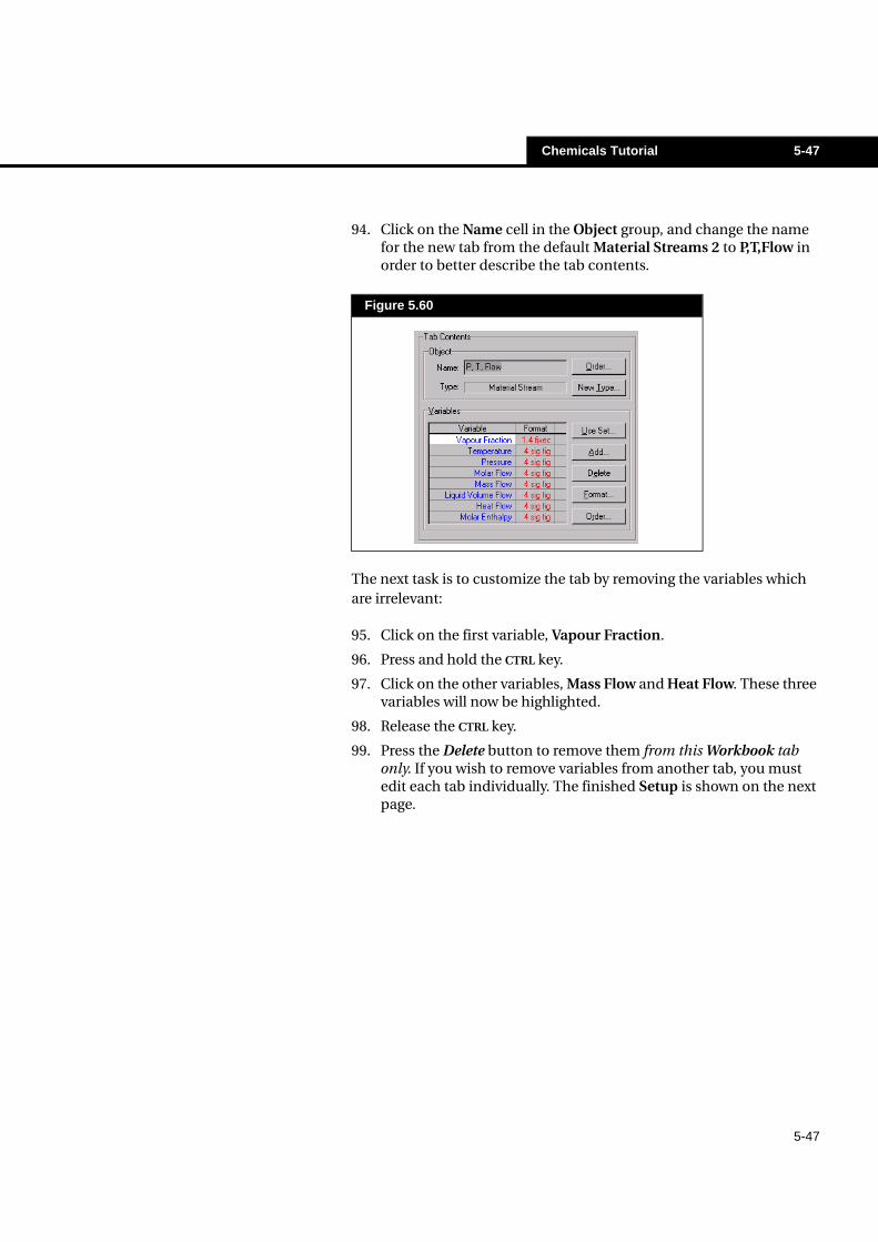
92. Press the Add button. The New Object Type view will appear.
93. Click on Material Stream and press the OK button. You will return to the Setup view, and the new tab will be added after the existing Material Streams tab.
Figure 5.58
Figure 5.59
Chemicals Tutorial 5-47
5-47
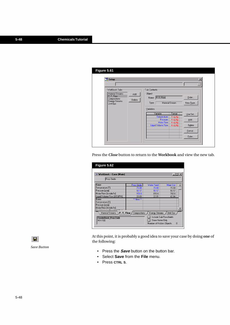
94. Click on the Name cell in the Object group, and change the name for the new tab from the default Material Streams 2 to P,T,Flow in order to better describe the tab contents.
The next task is to customize the tab by removing the variables which are irrelevant:
95. Click on the first variable, Vapour Fraction.
96. Press and hold the CTRL key.
97. Click on the other variables, Mass Flow and Heat Flow. These three variables will now be highlighted.
98. Release the CTRL key.
99. Press the Delete button to remove them from this Workbook tab only. If you wish to remove variables from another tab, you must edit each tab individually. The finished Setup is shown on the next page.
Figure 5.60
5-48 Chemicals Tutorial
5-48
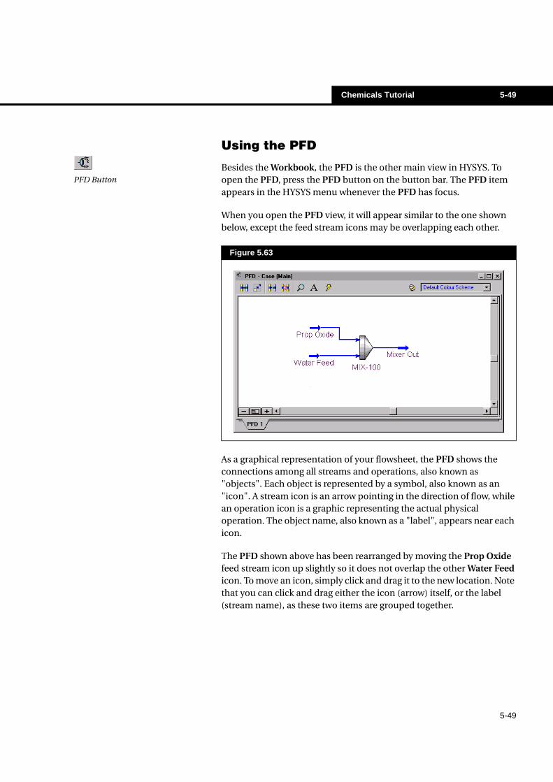
Press the Close button to return to the Workbook and view the new tab.
At this point, it is probably a good idea to save your case by doing one of the following:
• Press the Save button on the button bar.• Select Save from the File menu.• Press CTRL S.
Figure 5.61
Figure 5.62
Save Button
Chemicals Tutorial 5-49
5-49
Using the PFD
Besides the Workbook, the PFD is the other main view in HYSYS. To open the PFD, press the PFD button on the button bar. The PFD item appears in the HYSYS menu whenever the PFD has focus.
When you open the PFD view, it will appear similar to the one shown below, except the feed stream icons may be overlapping each other.
As a graphical representation of your flowsheet, the PFD shows the connections among all streams and operations, also known as "objects". Each object is represented by a symbol, also known as an "icon". A stream icon is an arrow pointing in the direction of flow, while an operation icon is a graphic representing the actual physical operation. The object name, also known as a "label", appears near each icon.
The PFD shown above has been rearranged by moving the Prop Oxide feed stream icon up slightly so it does not overlap the other Water Feed icon. To move an icon, simply click and drag it to the new location. Note that you can click and drag either the icon (arrow) itself, or the label (stream name), as these two items are grouped together.
Figure 5.63
PFD Button
5-50 Chemicals Tutorial
5-50
Like any other non-modal view, the PFD view can be re-sized by clicking and dragging anywhere on the outside border. Among other functions that can be performed while the PFD is active, you can:
• Access commands and features through the PFD Button Bar.• Open the property view for an object by double-clicking on its
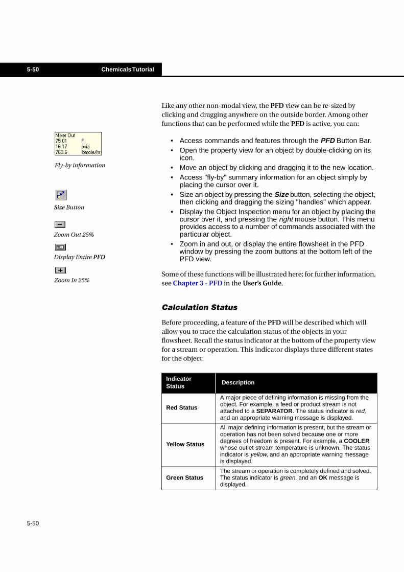
icon.• Move an object by clicking and dragging it to the new location.• Access "fly-by" summary information for an object simply by
placing the cursor over it.• Size an object by pressing the Size button, selecting the object,
then clicking and dragging the sizing "handles" which appear.• Display the Object Inspection menu for an object by placing the
cursor over it, and pressing the right mouse button. This menuprovides access to a number of commands associated with theparticular object.
• Zoom in and out, or display the entire flowsheet in the PFDwindow by pressing the zoom buttons at the bottom left of thePFD view.
Some of these functions will be illustrated here; for further information, see Chapter 3 - PFD in the User’s Guide.
Calculation Status
Before proceeding, a feature of the PFD will be described which will allow you to trace the calculation status of the objects in your flowsheet. Recall the status indicator at the bottom of the property view for a stream or operation. This indicator displays three different states for the object:
Fly-by information
Size Button
Zoom Out 25%
Display Entire PFD
Zoom In 25%
IndicatorStatus
Description
Red Status
A major piece of defining information is missing from theobject. For example, a feed or product stream is notattached to a SEPARATOR. The status indicator is red,and an appropriate warning message is displayed.
Yellow Status
All major defining information is present, but the stream oroperation has not been solved because one or moredegrees of freedom is present. For example, a COOLERwhose outlet stream temperature is unknown. The statusindicator is yellow, and an appropriate warning messageis displayed.
Green StatusThe stream or operation is completely defined and solved.The status indicator is green, and an OK message isdisplayed.
Chemicals Tutorial 5-51
5-51
When you are in the PFD, the streams and operations are "colour-coded" to indicate their calculation status. The MIXER is completely calculated, so its normal colours are displayed. However, if the conditions of an attached stream were not entirely known, the MIXER would have a yellow outline indicating its current status.
A similar colour scheme is used to indicate the status of streams. For material streams, a dark blue icon indicates the stream has been flashed and is entirely known. A light blue icon indicates the stream cannot be flashed until some additional information is supplied. Similarly, a dark red icon is for an energy stream with a known duty, while a light red icon indicates an unknown duty.
Installing the Reactor
For this example, a continuously-stirred-tank reactor operation (CSTR) will be used. You can install streams or operations by dropping them from the Object Palette onto the PFD. Make sure the Object Palette is displayed; if it is not, press F4. The CSTR will be added to the right of the MIXER, so if you need to make some empty space available, scroll to the right using the horizontal scroll bar. To install and connect the CSTR:
100. Press the CSTR Reactor button. If you press the wrong button, press the Cancel button.
Keep in mind that these are the HYSYS default colours; you may change the colours in the Session Preferences.
Notice that the icons for all streams installed to this point are dark blue.
CSTR Button
Cancel Button
5-52 Chemicals Tutorial
5-52
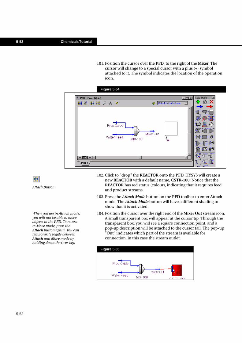
101. Position the cursor over the PFD, to the right of the Mixer. The cursor will change to a special cursor with a plus (+) symbol attached to it. The symbol indicates the location of the operation icon.
102. Click to "drop" the REACTOR onto the PFD. HYSYS will create a new REACTOR with a default name, CSTR-100. Notice that the REACTOR has red status (colour), indicating that it requires feed and product streams.
103. Press the Attach Mode button on the PFD toolbar to enter Attach mode. The Attach Mode button will have a different shading to show that it is activated.
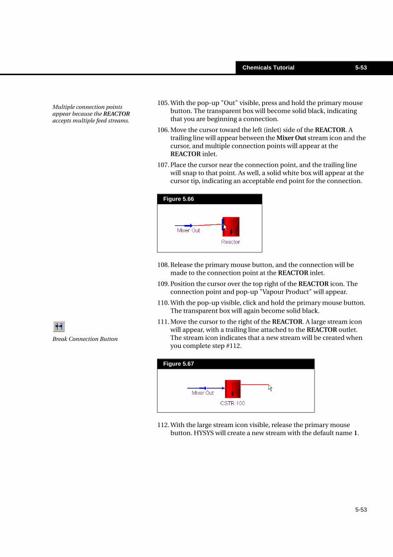
104. Position the cursor over the right end of the Mixer Out stream icon. A small transparent box will appear at the cursor tip. Through the transparent box, you will see a square connection point, and a pop-up description will be attached to the cursor tail. The pop-up "Out" indicates which part of the stream is available for connection, in this case the stream outlet.
Figure 5.64
Figure 5.65
Attach Button
When you are in Attach mode, you will not be able to move objects in the PFD. To return to Move mode, press the Attach button again. You can temporarily toggle between Attach and Move mode by holding down the CTRL key.
Chemicals Tutorial 5-53
5-53
105. With the pop-up "Out" visible, press and hold the primary mouse button. The transparent box will become solid black, indicating that you are beginning a connection.
106. Move the cursor toward the left (inlet) side of the REACTOR. A trailing line will appear between the Mixer Out stream icon and the cursor, and multiple connection points will appear at the REACTOR inlet.
107. Place the cursor near the connection point, and the trailing line will snap to that point. As well, a solid white box will appear at the cursor tip, indicating an acceptable end point for the connection.
108. Release the primary mouse button, and the connection will be made to the connection point at the REACTOR inlet.
109. Position the cursor over the top right of the REACTOR icon. The connection point and pop-up "Vapour Product" will appear.
110. With the pop-up visible, click and hold the primary mouse button. The transparent box will again become solid black.
111. Move the cursor to the right of the REACTOR. A large stream icon will appear, with a trailing line attached to the REACTOR outlet. The stream icon indicates that a new stream will be created when you complete step #112.
112. With the large stream icon visible, release the primary mouse button. HYSYS will create a new stream with the default name 1.
Figure 5.66
Figure 5.67
Multiple connection points appear because the REACTOR accepts multiple feed streams.
Break Connection Button
5-54 Chemicals Tutorial
5-54
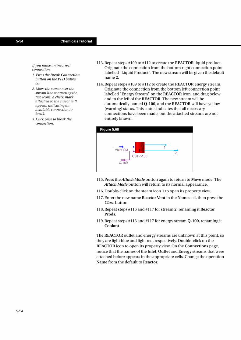
113. Repeat steps #109 to #112 to create the REACTOR liquid product. Originate the connection from the bottom right connection point labelled "Liquid Product". The new stream will be given the default name 2.
114. Repeat steps #109 to #112 to create the REACTOR energy stream. Originate the connection from the bottom left connection point labelled "Energy Stream" on the REACTOR icon, and drag below and to the left of the REACTOR. The new stream will be automatically named Q-100, and the REACTOR will have yellow (warning) status. This status indicates that all necessary connections have been made, but the attached streams are not entirely known.
115. Press the Attach Mode button again to return to Move mode. The Attach Mode button will return to its normal appearance.
116. Double-click on the steam icon 1 to open its property view.
117. Enter the new name Reactor Vent in the Name cell, then press the Close button.
118. Repeat steps #116 and #117 for stream 2, renaming it Reactor Prods.
119. Repeat steps #116 and #117 for energy stream Q-100, renaming it Coolant.
The REACTOR outlet and energy streams are unknown at this point, so they are light blue and light red, respectively. Double-click on the REACTOR icon to open its property view. On the Connections page, notice that the names of the Inlet, Outlet and Energy streams that were attached before appears in the appropriate cells. Change the operation Name from the default to Reactor.
Figure 5.68
If you make an incorrect connection,
1. Press the Break Connection button on the PFD button bar
2. Move the cursor over the stream line connecting the two icons. A check mark attached to the cursor will appear, indicating an available connection to break.
3. Click once to break the connection.
Chemicals Tutorial 5-55
5-55
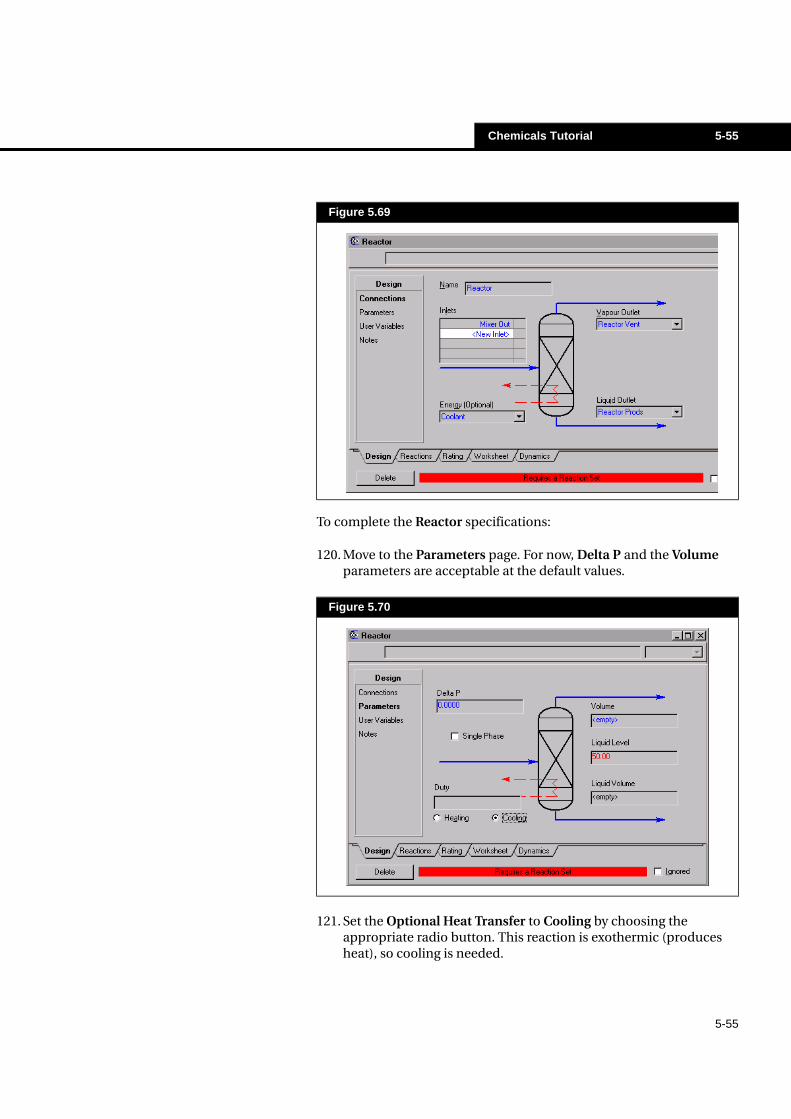
To complete the Reactor specifications:
120. Move to the Parameters page. For now, Delta P and the Volume parameters are acceptable at the default values.
121. Set the Optional Heat Transfer to Cooling by choosing the appropriate radio button. This reaction is exothermic (produces heat), so cooling is needed.
Figure 5.69
Figure 5.70
5-56 Chemicals Tutorial
5-56
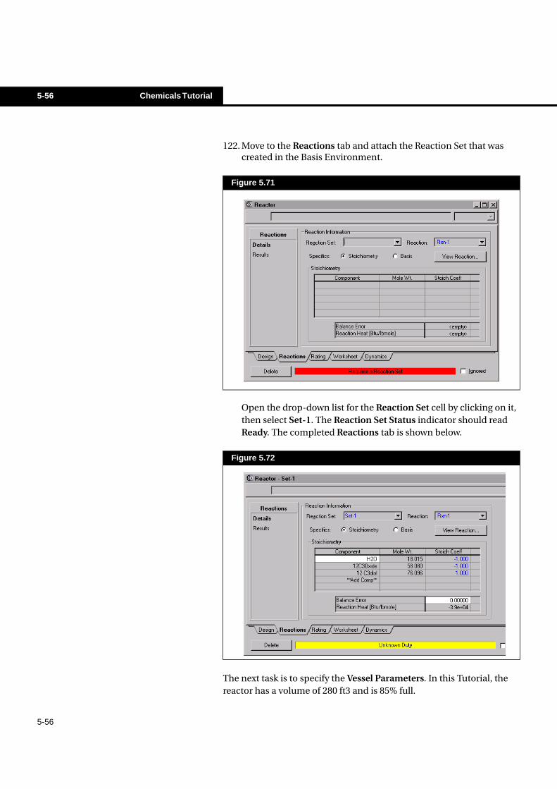
122. Move to the Reactions tab and attach the Reaction Set that was created in the Basis Environment.
Open the drop-down list for the Reaction Set cell by clicking on it, then select Set-1. The Reaction Set Status indicator should read Ready. The completed Reactions tab is shown below.
The next task is to specify the Vessel Parameters. In this Tutorial, the reactor has a volume of 280 ft3 and is 85% full.
Figure 5.71
Figure 5.72
Chemicals Tutorial 5-57
5-57
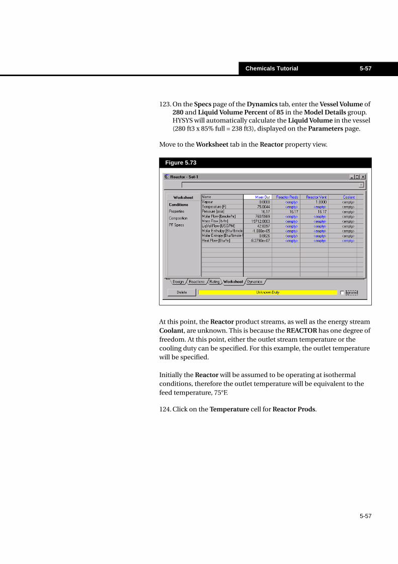
123. On the Specs page of the Dynamics tab, enter the Vessel Volume of 280 and Liquid Volume Percent of 85 in the Model Details group. HYSYS will automatically calculate the Liquid Volume in the vessel (280 ft3 x 85% full = 238 ft3), displayed on the Parameters page.
Move to the Worksheet tab in the Reactor property view.
At this point, the Reactor product streams, as well as the energy stream Coolant, are unknown. This is because the REACTOR has one degree of freedom. At this point, either the outlet stream temperature or the cooling duty can be specified. For this example, the outlet temperature will be specified.
Initially the Reactor will be assumed to be operating at isothermal conditions, therefore the outlet temperature will be equivalent to the feed temperature, 75°F.
124. Click on the Temperature cell for Reactor Prods.
Figure 5.73
5-58 Chemicals Tutorial
5-58
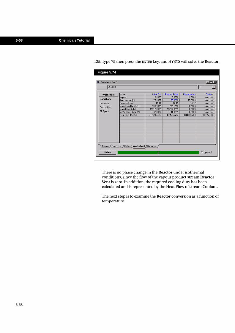
125. Type 75 then press the ENTER key, and HYSYS will solve the Reactor.
There is no phase change in the Reactor under isothermal conditions, since the flow of the vapour product stream Reactor Vent is zero. In addition, the required cooling duty has been calculated and is represented by the Heat Flow of stream Coolant.
The next step is to examine the Reactor conversion as a function of temperature.
Figure 5.74
Chemicals Tutorial 5-59
5-59
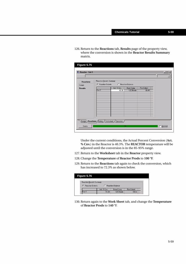
126. Return to the Reactions tab, Results page of the property view, where the conversion is shown in the Reactor Results Summary matrix.
Under the current conditions, the Actual Percent Conversion (Act. % Cnv.) in the Reactor is 40.3%. The REACTOR temperature will be adjusted until the conversion is in the 85-95% range.
127. Return to the Worksheet tab in the Reactor property view.
128. Change the Temperature of Reactor Prods to 100 °F.
129. Return to the Reactions tab again to check the conversion, which has increased to 72.3% as shown below.
130. Return again to the Work Sheet tab, and change the Temperature of Reactor Prods to 140 °F.
Figure 5.75
Figure 5.76
5-60 Chemicals Tutorial
5-60
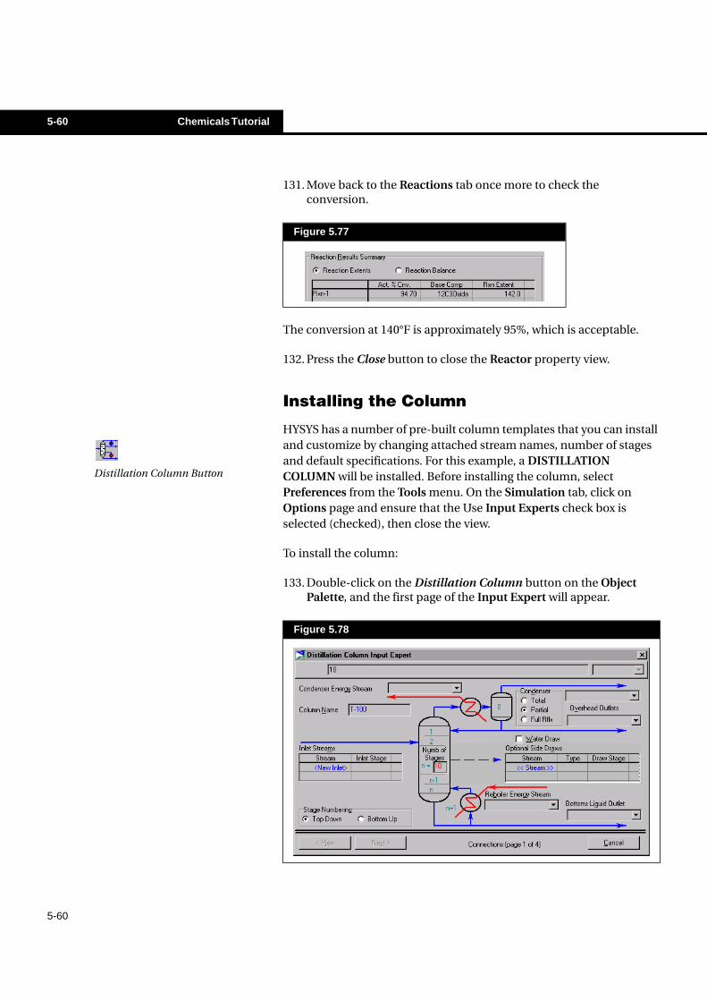
131. Move back to the Reactions tab once more to check the conversion.
The conversion at 140°F is approximately 95%, which is acceptable.
132. Press the Close button to close the Reactor property view.
Installing the Column
HYSYS has a number of pre-built column templates that you can install and customize by changing attached stream names, number of stages and default specifications. For this example, a DISTILLATION COLUMN will be installed. Before installing the column, select Preferences from the Tools menu. On the Simulation tab, click on Options page and ensure that the Use Input Experts check box is selected (checked), then close the view.
To install the column:
133. Double-click on the Distillation Column button on the Object Palette, and the first page of the Input Expert will appear.
Figure 5.77
Figure 5.78
Distillation Column Button
Chemicals Tutorial 5-61
5-61
134. When you install a column using a pre-built template, HYSYS supplies certain default information, such as the number of stages. The current active cell is Numb of Stages, indicated by the thick border around this cell, and the presence of 10 (default number of stages) in the Edit Bar at the top of the view. Some points worth noting are:
• These are theoretical stages, as the HYSYS default stageefficiency is one.
• The Condenser and Reboiler are considered separate from theother stages, and are not included in the Num of Stages field.
For this example, 10 theoretical stages will be used, so leave the Numb of Stages at its default value.
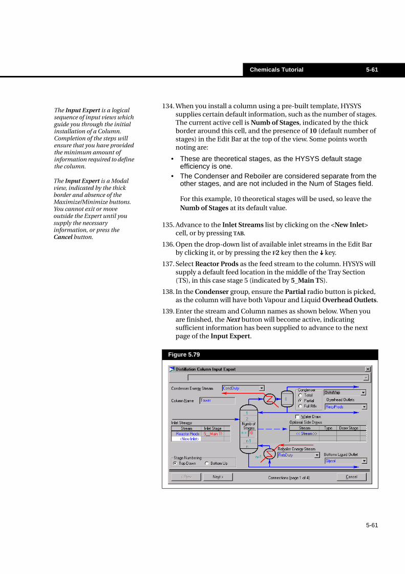
135. Advance to the Inlet Streams list by clicking on the <New Inlet> cell, or by pressing TAB.
136. Open the drop-down list of available inlet streams in the Edit Bar by clicking it, or by pressing the F2 key then the ���� key.
137. Select Reactor Prods as the feed stream to the column. HYSYS will supply a default feed location in the middle of the Tray Section (TS), in this case stage 5 (indicated by 5_Main TS).
138. In the Condenser group, ensure the Partial radio button is picked, as the column will have both Vapour and Liquid Overhead Outlets.
139. Enter the stream and Column names as shown below. When you are finished, the Next button will become active, indicating sufficient information has been supplied to advance to the next page of the Input Expert.
Figure 5.79
The Input Expert is a logical sequence of input views which guide you through the initial installation of a Column. Completion of the steps will ensure that you have provided the minimum amount of information required to define the column.
The Input Expert is a Modal view, indicated by the thick border and absence of the Maximize/Minimize buttons. You cannot exit or move outside the Expert until you supply the necessary information, or press the Cancel button.
5-62 Chemicals Tutorial
5-62
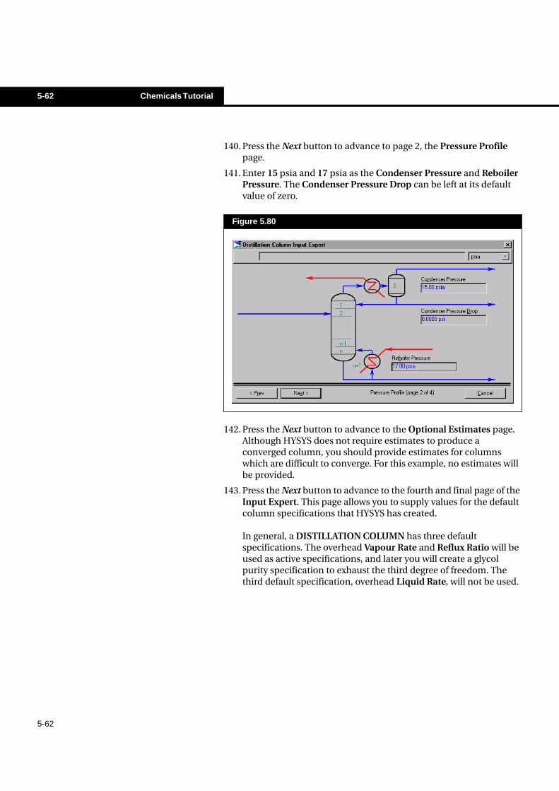
140. Press the Next button to advance to page 2, the Pressure Profile page.
141. Enter 15 psia and 17 psia as the Condenser Pressure and Reboiler Pressure. The Condenser Pressure Drop can be left at its default value of zero.
142. Press the Next button to advance to the Optional Estimates page. Although HYSYS does not require estimates to produce a converged column, you should provide estimates for columns which are difficult to converge. For this example, no estimates will be provided.
143. Press the Next button to advance to the fourth and final page of the Input Expert. This page allows you to supply values for the default column specifications that HYSYS has created.
In general, a DISTILLATION COLUMN has three default specifications. The overhead Vapour Rate and Reflux Ratio will be used as active specifications, and later you will create a glycol purity specification to exhaust the third degree of freedom. The third default specification, overhead Liquid Rate, will not be used.
Figure 5.80
Chemicals Tutorial 5-63
5-63
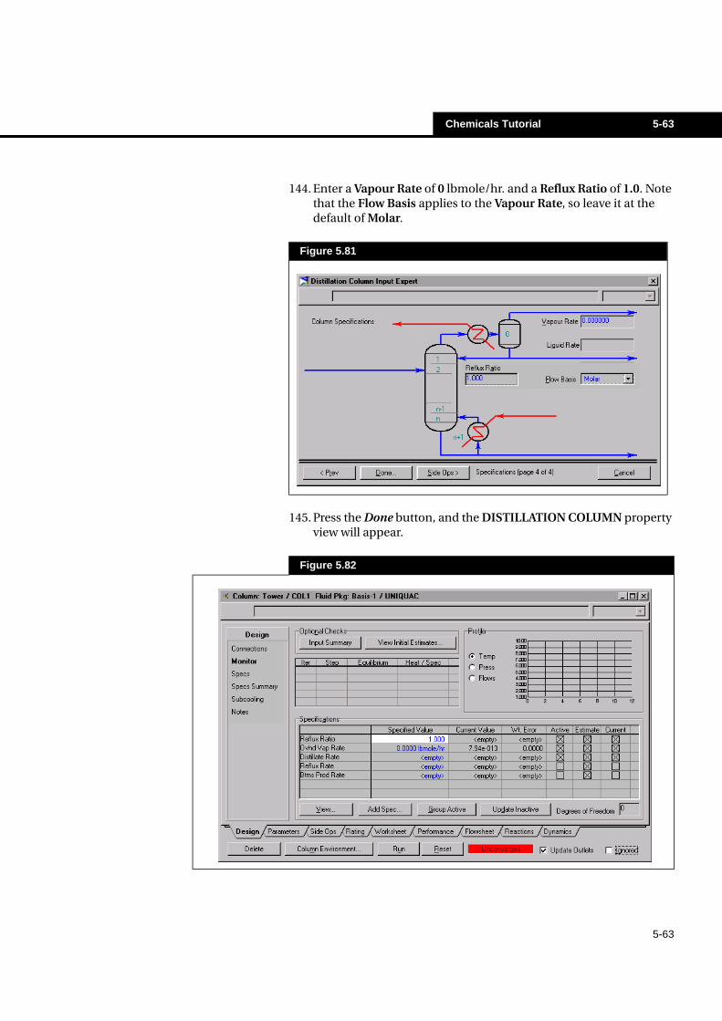
144. Enter a Vapour Rate of 0 lbmole/hr. and a Reflux Ratio of 1.0. Note that the Flow Basis applies to the Vapour Rate, so leave it at the default of Molar.
145. Press the Done button, and the DISTILLATION COLUMN property view will appear.
Figure 5.81
Figure 5.82
5-64 Chemicals Tutorial
5-64
You are automatically placed on the Monitor page of the Column property view. The main feature of this page is that it displays the status of your column as it is being calculated, updating information with each iteration. You can also change specification values, and activate or de-activate specifications used by the Column solver, directly from this page.
Adding a Column Specification
Notice that the current Degrees of Freedom is zero, indicating the column is ready to be Run. However, the Distillate Rate (Overhead Liquid Rate for which no value was provided in the Input Expert) is currently an Active specification, and has a Specified Value of <empty>. Since it is not desired to use this specification, click the Active check box for the Distillate Rate to clear it. The Degrees of Freedom will increase to 1, indicating that another active specification is required. For this example, a water mole fraction of 0.005 will be specified in the glycol product stream. To add the new specification:
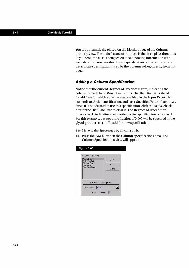
146. Move to the Specs page by clicking on it.
147. Press the Add button in the Column Specifications area. The Column Specifications view will appear.
Figure 5.83
Chemicals Tutorial 5-65
5-65
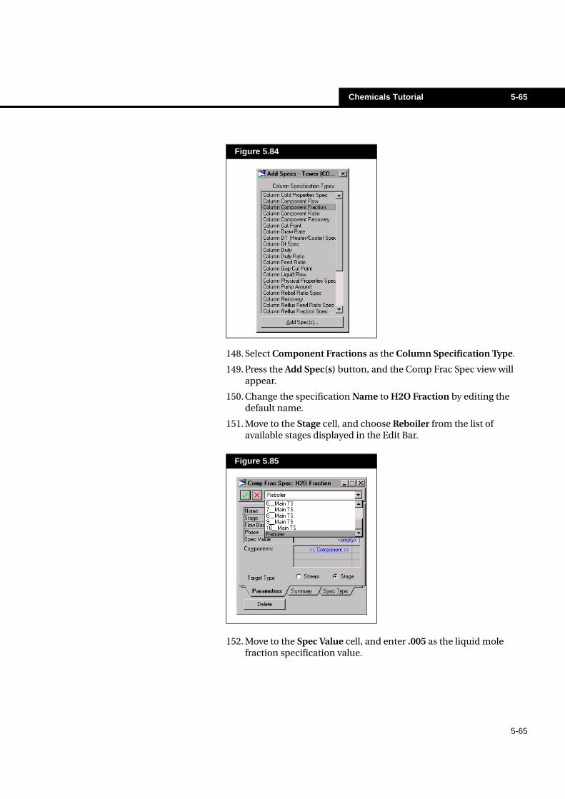
148. Select Component Fractions as the Column Specification Type.
149. Press the Add Spec(s) button, and the Comp Frac Spec view will appear.
150. Change the specification Name to H2O Fraction by editing the default name.
151. Move to the Stage cell, and choose Reboiler from the list of available stages displayed in the Edit Bar.
152. Move to the Spec Value cell, and enter .005 as the liquid mole fraction specification value.
Figure 5.84
Figure 5.85
5-66 Chemicals Tutorial
5-66
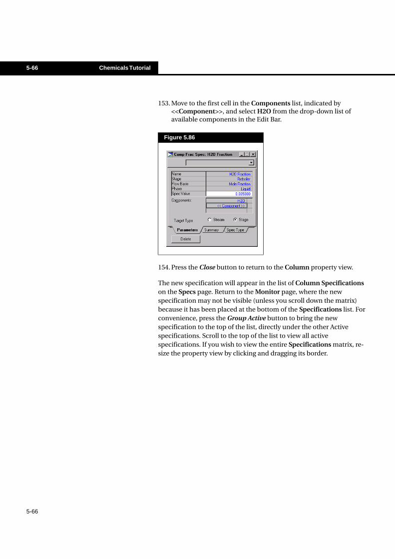
153. Move to the first cell in the Components list, indicated by <<Component>>, and select H2O from the drop-down list of available components in the Edit Bar.
154. Press the Close button to return to the Column property view.
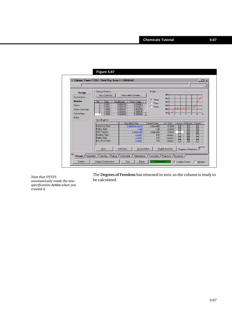
The new specification will appear in the list of Column Specifications on the Specs page. Return to the Monitor page, where the new specification may not be visible (unless you scroll down the matrix) because it has been placed at the bottom of the Specifications list. For convenience, press the Group Active button to bring the new specification to the top of the list, directly under the other Active specifications. Scroll to the top of the list to view all active specifications. If you wish to view the entire Specifications matrix, re-size the property view by clicking and dragging its border.
Figure 5.86
Chemicals Tutorial 5-67
5-67
The Degrees of Freedom has returned to zero, so the column is ready to be calculated.
Figure 5.87
Note that HYSYS automatically made the new specification Active when you created it.
5-68 Chemicals Tutorial
5-68
Running the Column
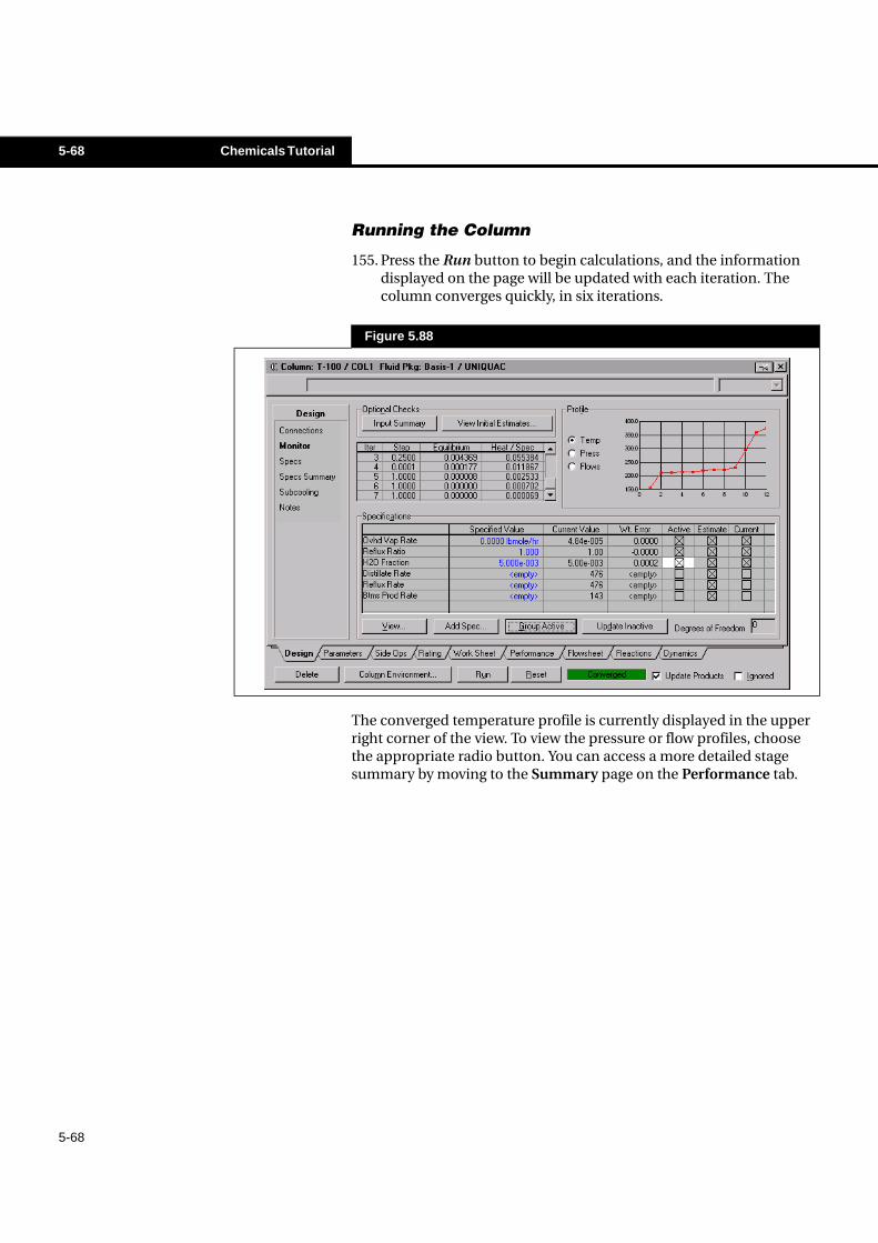
155. Press the Run button to begin calculations, and the information displayed on the page will be updated with each iteration. The column converges quickly, in six iterations.
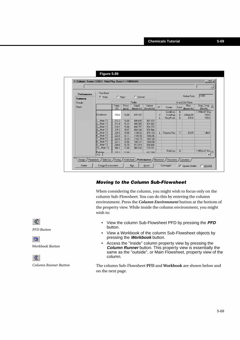
The converged temperature profile is currently displayed in the upper right corner of the view. To view the pressure or flow profiles, choose the appropriate radio button. You can access a more detailed stage summary by moving to the Summary page on the Performance tab.
Figure 5.88
Chemicals Tutorial 5-69
5-69
Moving to the Column Sub-Flowsheet
When considering the column, you might wish to focus only on the column Sub-Flowsheet. You can do this by entering the column environment. Press the Column Environment button at the bottom of the property view. While inside the column environment, you might wish to:
• View the column Sub-Flowsheet PFD by pressing the PFDbutton.
• View a Workbook of the column Sub-Flowsheet objects bypressing the Workbook button.
• Access the "inside" column property view by pressing theColumn Runner button. This property view is essentially thesame as the "outside", or Main Flowsheet, property view of thecolumn.
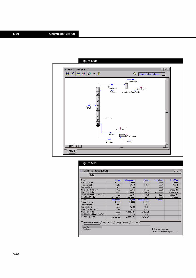
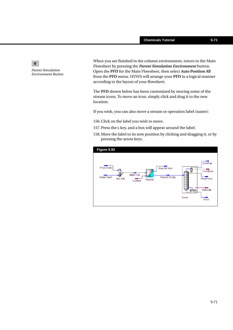
The column Sub-Flowsheet PFD and Workbook are shown below and on the next page.
Figure 5.89
PFD Button
Column Runner Button
Workbook Button
5-70 Chemicals Tutorial
5-70
Figure 5.90
Figure 5.91
Chemicals Tutorial 5-71
5-71
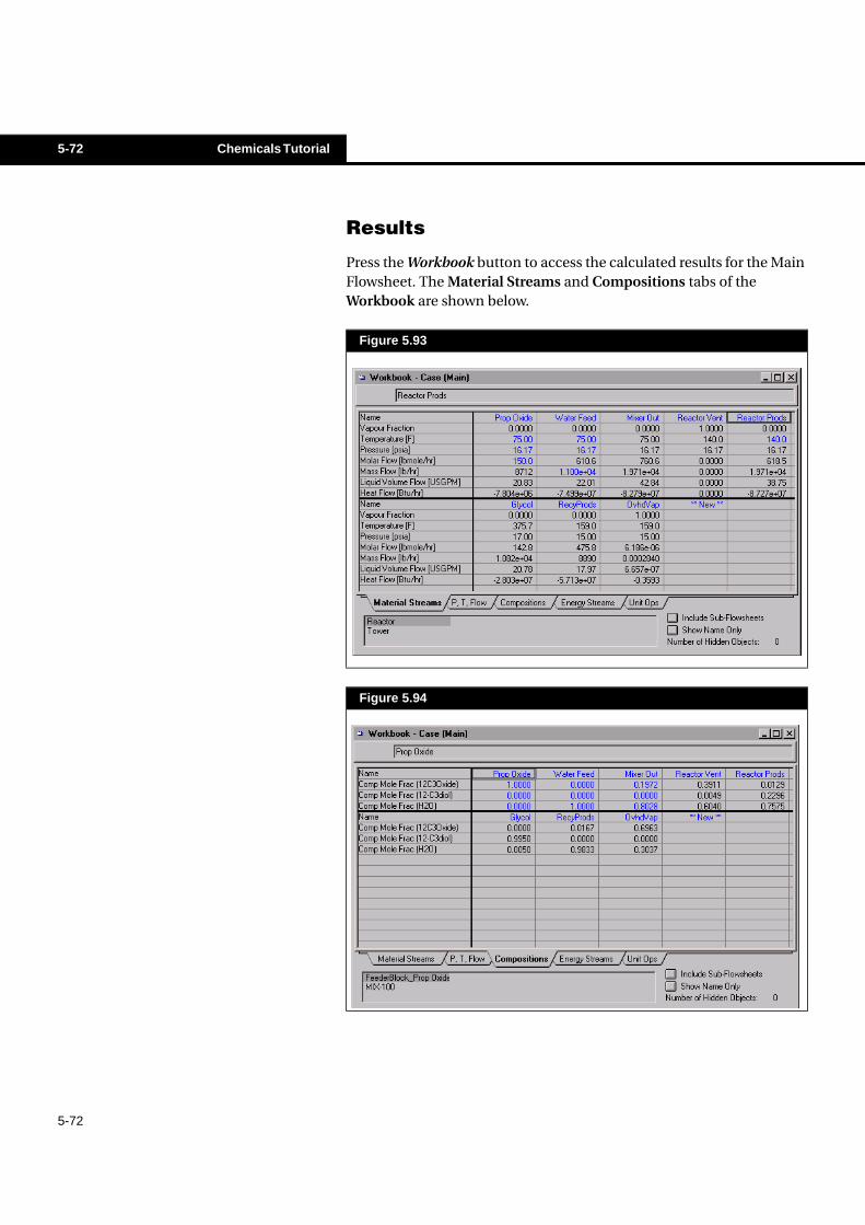
When you are finished in the column environment, return to the Main Flowsheet by pressing the Parent Simulation Environment button. Open the PFD for the Main Flowsheet, then select Auto Position All from the PFD menu. HYSYS will arrange your PFD in a logical manner according to the layout of your flowsheet.
The PFD shown below has been customized by moving some of the stream icons. To move an icon, simply click and drag it to the new location.
If you wish, you can also move a stream or operation label (name):
156. Click on the label you wish to move.
157. Press the L key, and a box will appear around the label.
158. Move the label to its new position by clicking and dragging it, or by pressing the arrow keys.
Figure 5.92
Parent Simulation Environment Button
5-72 Chemicals Tutorial
5-72
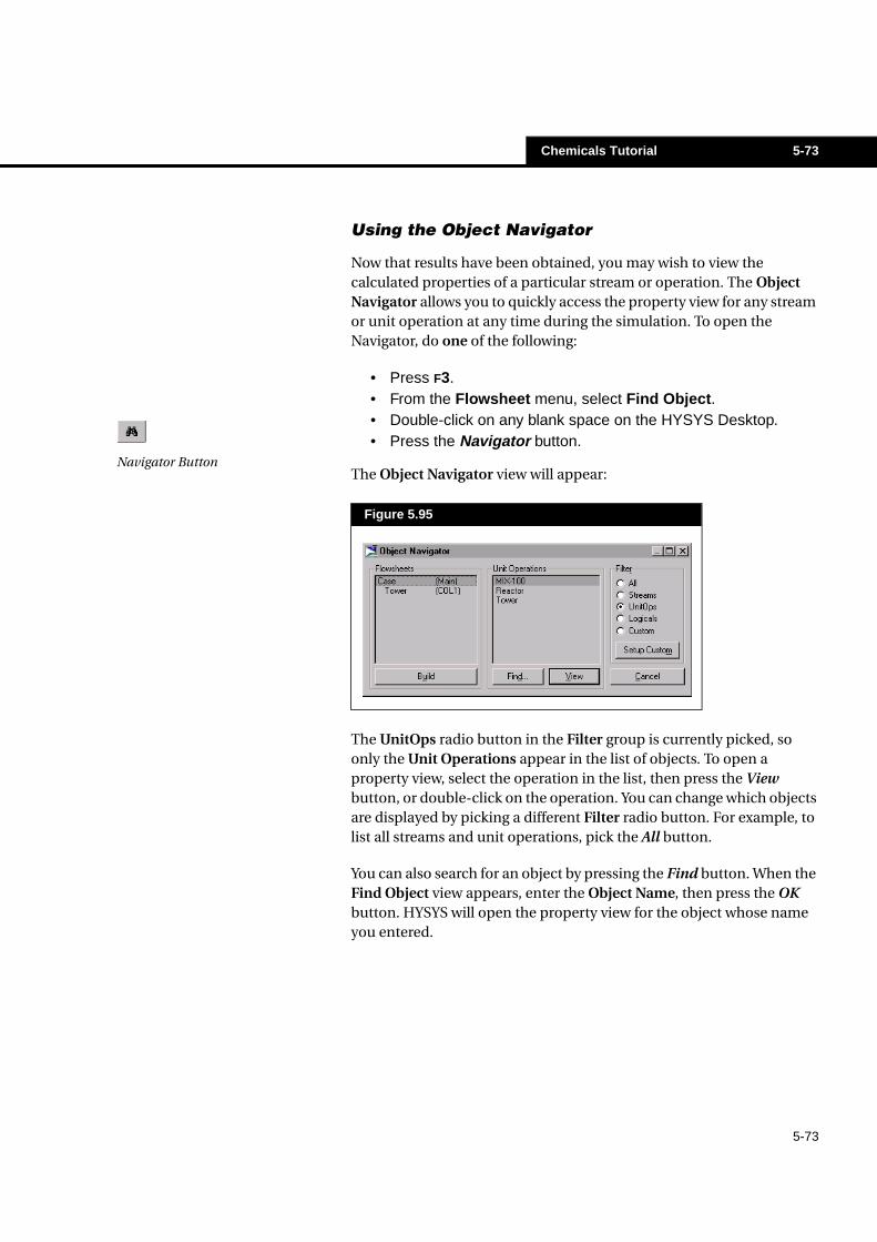
Results
Press the Workbook button to access the calculated results for the Main Flowsheet. The Material Streams and Compositions tabs of the Workbook are shown below.
Figure 5.93
Figure 5.94
Chemicals Tutorial 5-73
5-73
Using the Object Navigator
Now that results have been obtained, you may wish to view the calculated properties of a particular stream or operation. The Object Navigator allows you to quickly access the property view for any stream or unit operation at any time during the simulation. To open the Navigator, do one of the following:
• Press F3.• From the Flowsheet menu, select Find Object.• Double-click on any blank space on the HYSYS Desktop.• Press the Navigator button.
The Object Navigator view will appear:
The UnitOps radio button in the Filter group is currently picked, so only the Unit Operations appear in the list of objects. To open a property view, select the operation in the list, then press the View button, or double-click on the operation. You can change which objects are displayed by picking a different Filter radio button. For example, to list all streams and unit operations, pick the All button.
You can also search for an object by pressing the Find button. When the Find Object view appears, enter the Object Name, then press the OK button. HYSYS will open the property view for the object whose name you entered.
Figure 5.95
Navigator Button
5-74 Chemicals Tutorial
5-74
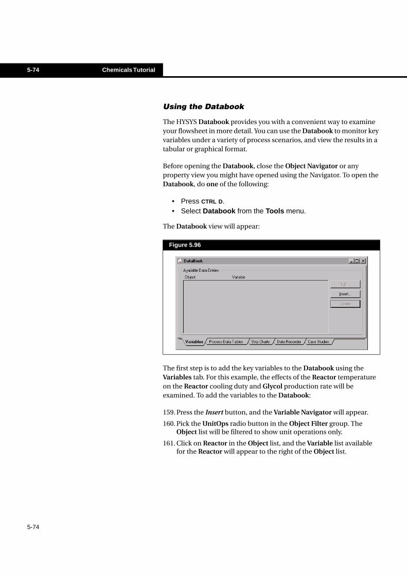
Using the Databook
The HYSYS Databook provides you with a convenient way to examine your flowsheet in more detail. You can use the Databook to monitor key variables under a variety of process scenarios, and view the results in a tabular or graphical format.
Before opening the Databook, close the Object Navigator or any property view you might have opened using the Navigator. To open the Databook, do one of the following:
• Press CTRL D.• Select Databook from the Tools menu.
The Databook view will appear:
The first step is to add the key variables to the Databook using the Variables tab. For this example, the effects of the Reactor temperature on the Reactor cooling duty and Glycol production rate will be examined. To add the variables to the Databook:
159. Press the Insert button, and the Variable Navigator will appear.
160. Pick the UnitOps radio button in the Object Filter group. The Object list will be filtered to show unit operations only.
161. Click on Reactor in the Object list, and the Variable list available for the Reactor will appear to the right of the Object list.
Figure 5.96
Chemicals Tutorial 5-75
5-75
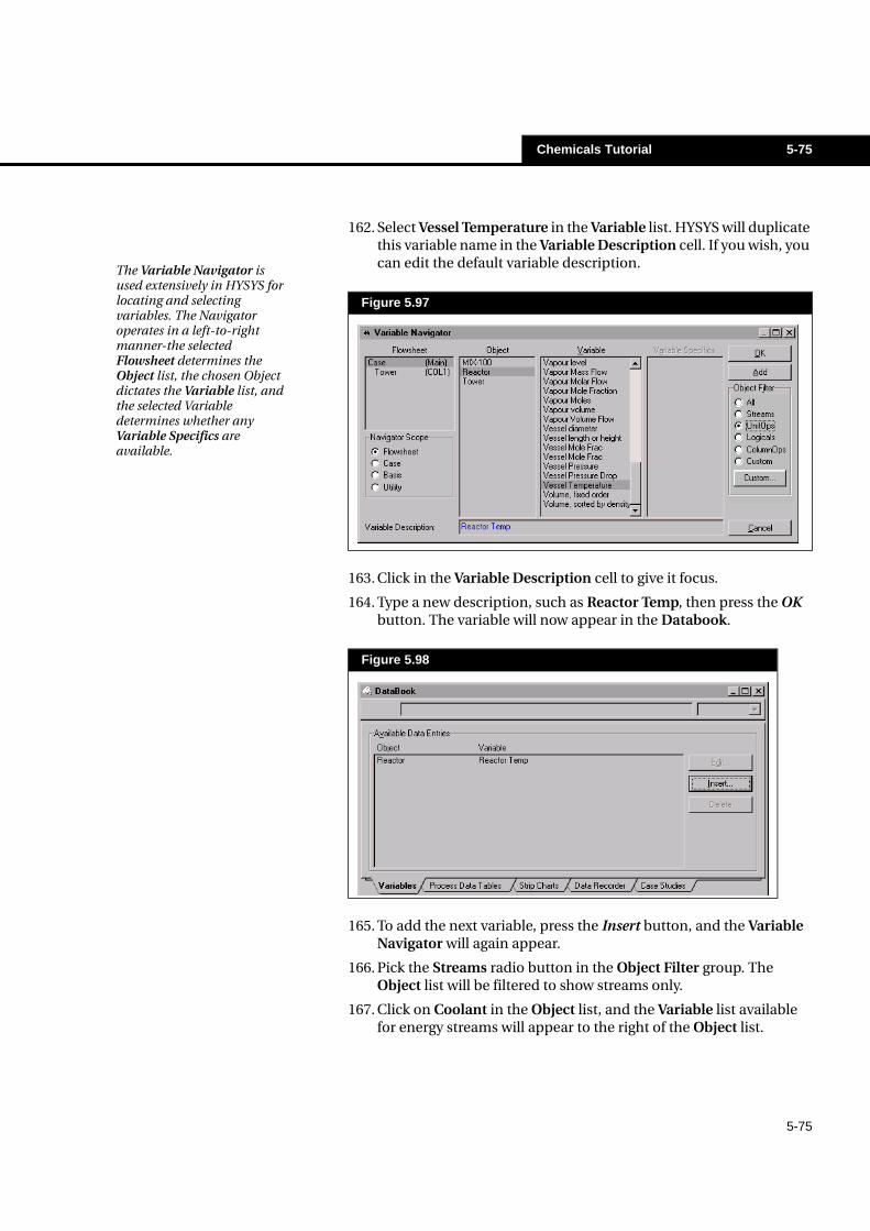
162. Select Vessel Temperature in the Variable list. HYSYS will duplicate this variable name in the Variable Description cell. If you wish, you can edit the default variable description.
163. Click in the Variable Description cell to give it focus.
164. Type a new description, such as Reactor Temp, then press the OK button. The variable will now appear in the Databook.
165. To add the next variable, press the Insert button, and the Variable Navigator will again appear.
166. Pick the Streams radio button in the Object Filter group. The Object list will be filtered to show streams only.
167. Click on Coolant in the Object list, and the Variable list available for energy streams will appear to the right of the Object list.
Figure 5.97
Figure 5.98
The Variable Navigator is used extensively in HYSYS for locating and selecting variables. The Navigator operates in a left-to-right manner-the selected Flowsheet determines the Object list, the chosen Object dictates the Variable list, and the selected Variable determines whether any Variable Specifics are available.
5-76 Chemicals Tutorial
5-76
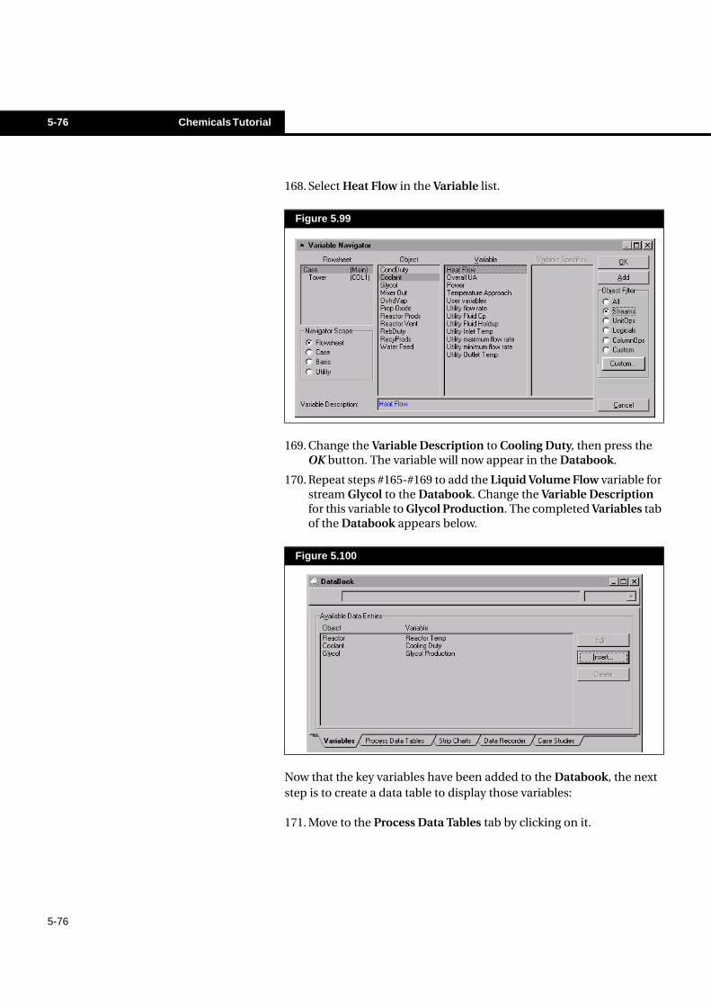
168. Select Heat Flow in the Variable list.
169. Change the Variable Description to Cooling Duty, then press the OK button. The variable will now appear in the Databook.
170. Repeat steps #165-#169 to add the Liquid Volume Flow variable for stream Glycol to the Databook. Change the Variable Description for this variable to Glycol Production. The completed Variables tab of the Databook appears below.
Now that the key variables have been added to the Databook, the next step is to create a data table to display those variables:
171. Move to the Process Data Tables tab by clicking on it.
Figure 5.99
Figure 5.100
Chemicals Tutorial 5-77
5-77
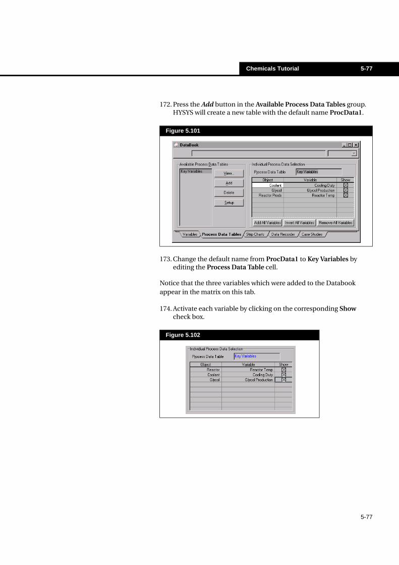
172. Press the Add button in the Available Process Data Tables group. HYSYS will create a new table with the default name ProcData1.
173. Change the default name from ProcData1 to Key Variables by editing the Process Data Table cell.
Notice that the three variables which were added to the Databook appear in the matrix on this tab.
174. Activate each variable by clicking on the corresponding Show check box.
Figure 5.101
Figure 5.102
5-78 Chemicals Tutorial
5-78
175. Press the View button to view the new data table, which is shown below.
This table will be accessed again later to demonstrate how its results are updated whenever a flowsheet change is made. For now, press the Minimize button in the upper right corner of the Key Variables Data view. HYSYS will reduce the view to an icon and place it at the bottom of the Desktop.
Suppose you now wish to make changes to the flowsheet, but you would like to record the current values of the key variables before making any changes. Instead of manually recording the variables, you can use the Data Recorder to automatically record them for you. To record the current values:
176. Move to the Data Recorder tab in the Databook by clicking on it. This page appears below.
Figure 5.103
Figure 5.104
Chemicals Tutorial 5-79
5-79
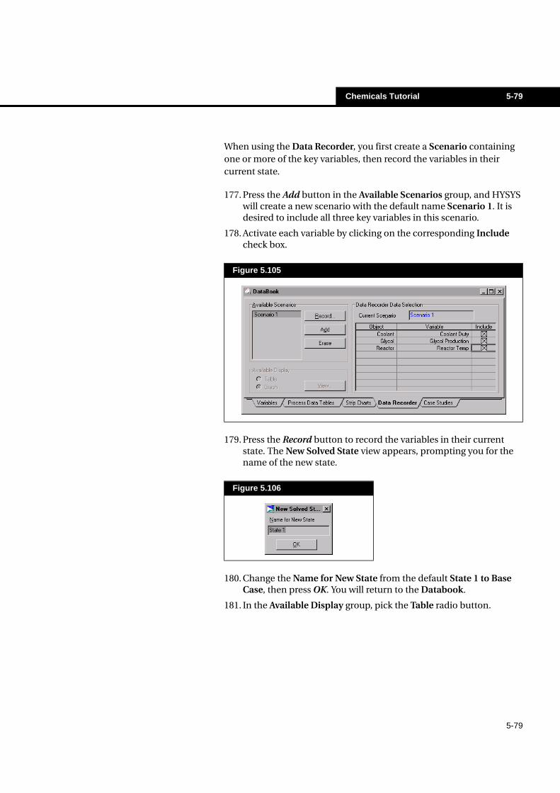
When using the Data Recorder, you first create a Scenario containing one or more of the key variables, then record the variables in their current state.
177. Press the Add button in the Available Scenarios group, and HYSYS will create a new scenario with the default name Scenario 1. It is desired to include all three key variables in this scenario.
178. Activate each variable by clicking on the corresponding Include check box.
179. Press the Record button to record the variables in their current state. The New Solved State view appears, prompting you for the name of the new state.
180. Change the Name for New State from the default State 1 to Base Case, then press OK. You will return to the Databook.
181. In the Available Display group, pick the Table radio button.
Figure 5.105
Figure 5.106
5-80 Chemicals Tutorial
5-80
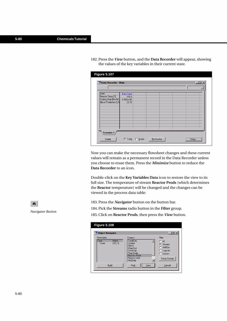
182. Press the View button, and the Data Recorder will appear, showing the values of the key variables in their current state.
Now you can make the necessary flowsheet changes and these current values will remain as a permanent record in the Data Recorder unless you choose to erase them. Press the Minimize button to reduce the Data Recorder to an icon.
Double-click on the Key Variables Data icon to restore the view to its full size. The temperature of stream Reactor Prods (which determines the Reactor temperature) will be changed and the changes can be viewed in the process data table:
183. Press the Navigator button on the button bar.
184. Pick the Streams radio button in the Filter group.
185. Click on Reactor Prods, then press the View button.
Figure 5.107
Figure 5.108
Navigator Button
Chemicals Tutorial 5-81
5-81
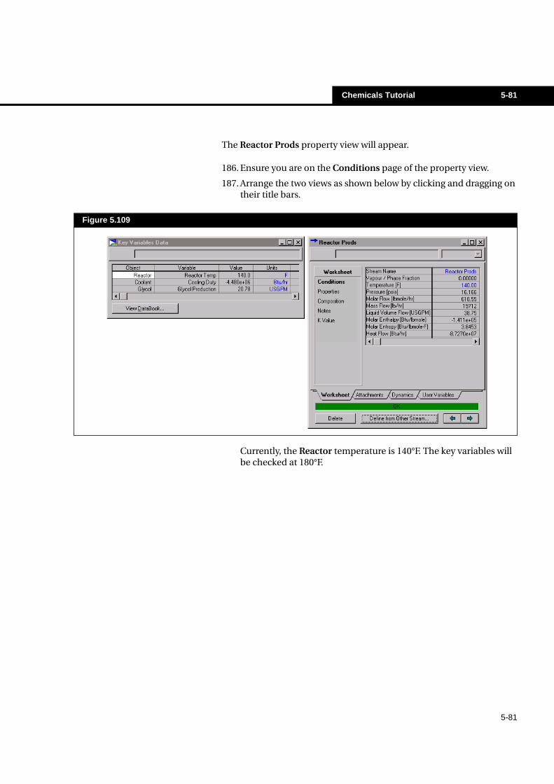
The Reactor Prods property view will appear.
186. Ensure you are on the Conditions page of the property view.
187. Arrange the two views as shown below by clicking and dragging on their title bars.
Currently, the Reactor temperature is 140°F. The key variables will be checked at 180°F.
Figure 5.109
5-82 Chemicals Tutorial
5-82
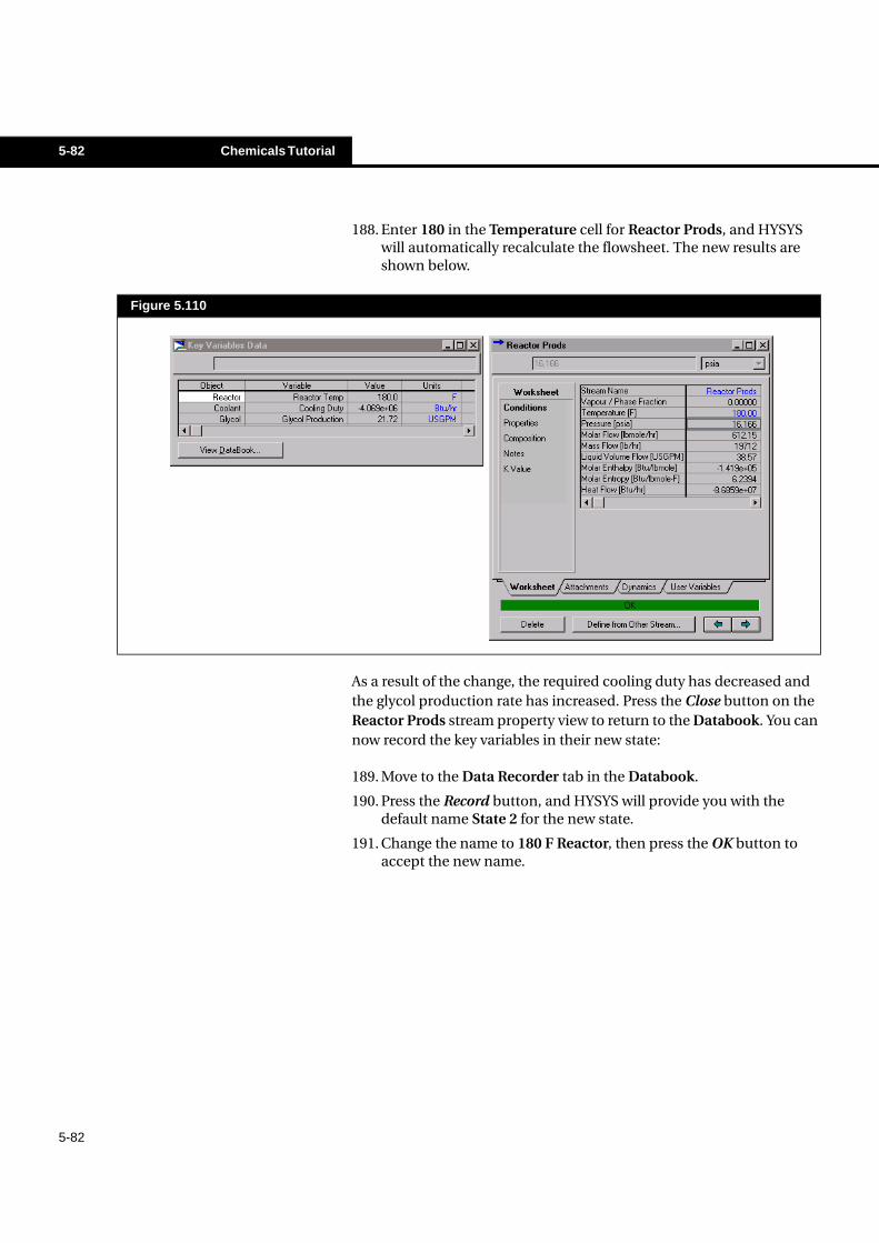
188. Enter 180 in the Temperature cell for Reactor Prods, and HYSYS will automatically recalculate the flowsheet. The new results are shown below.
As a result of the change, the required cooling duty has decreased and the glycol production rate has increased. Press the Close button on the Reactor Prods stream property view to return to the Databook. You can now record the key variables in their new state:
189. Move to the Data Recorder tab in the Databook.
190. Press the Record button, and HYSYS will provide you with the default name State 2 for the new state.
191. Change the name to 180 F Reactor, then press the OK button to accept the new name.
Figure 5.110
Chemicals Tutorial 5-83
5-83
192. Press the View button and the Data Recorder will appear, displaying the new values of the variables.
Press the Close button on the Data Recorder, then on the Databook and finally on the Process Data Table.
This completes the HYSYS Chemicals tutorial. If there are any aspects of this case that you would like to explore further, feel free to continue working on this simulation on your own.
Further Study
For other chemical case examples, see the Applications binder. Applications named beginning with “C” explore some of the types of chemical simulations that can be built using HYSYS.
Figure 5.111
Peter Styring
Details of the practical class requirements are given on the printed sheet.