49
Kenosha Wastewater Treatment Plant Energy Optimized Resource Recovery Project Presented By: Curtis Czarnecki, P.E. Kenosha Water Utility March 22, 2016
Kenosha Wastewater Treatment Plant
Energy Optimized Resource Recovery Project
Presented By:
Curtis Czarnecki, P.E.
Kenosha Water UtilityMarch 22, 2016
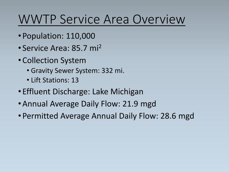
WWTP Service Area Overview•Population: 110,000
•Service Area: 85.7 mi2
•Collection System• Gravity Sewer System: 332 mi.• Lift Stations: 13
•Effluent Discharge: Lake Michigan
•Annual Average Daily Flow: 21.9 mgd
•Permitted Average Annual Daily Flow: 28.6 mgd
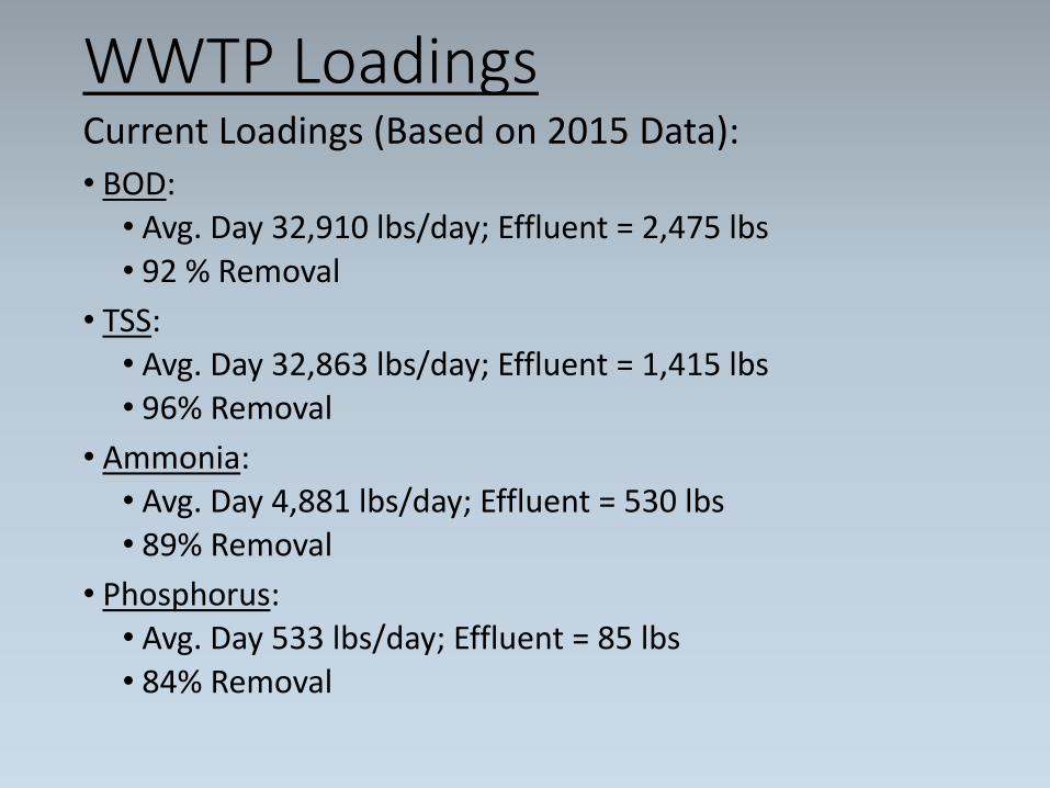
WWTP LoadingsCurrent Loadings (Based on 2015 Data):
• BOD:• Avg. Day 32,910 lbs/day; Effluent = 2,475 lbs• 92 % Removal
• TSS:• Avg. Day 32,863 lbs/day; Effluent = 1,415 lbs• 96% Removal
• Ammonia:• Avg. Day 4,881 lbs/day; Effluent = 530 lbs• 89% Removal
• Phosphorus:• Avg. Day 533 lbs/day; Effluent = 85 lbs• 84% Removal
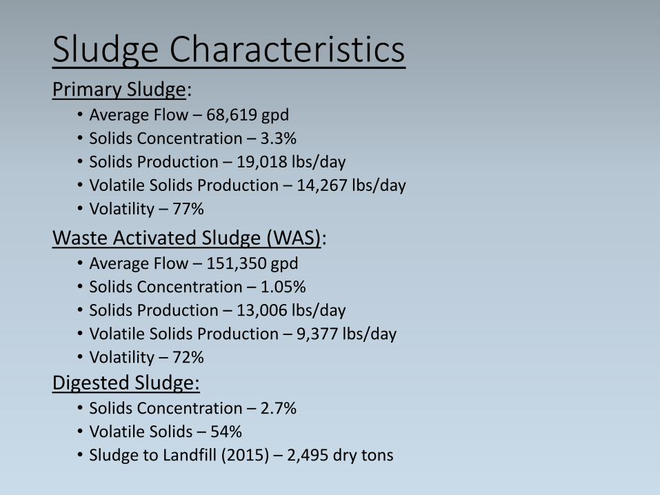
Sludge CharacteristicsPrimary Sludge:
• Average Flow – 68,619 gpd
• Solids Concentration – 3.3%
• Solids Production – 19,018 lbs/day
• Volatile Solids Production – 14,267 lbs/day
• Volatility – 77%
Waste Activated Sludge (WAS):• Average Flow – 151,350 gpd
• Solids Concentration – 1.05%
• Solids Production – 13,006 lbs/day
• Volatile Solids Production – 9,377 lbs/day
• Volatility – 72%
Digested Sludge:• Solids Concentration – 2.7%
• Volatile Solids – 54%
• Sludge to Landfill (2015) – 2,495 dry tons
Motivation Behind Project
•Aging WWTP infrastructure
•An effort to combat ever rising utility costs:•Natural Gas•Electricity
•Reduce or eliminate landfill disposal fees
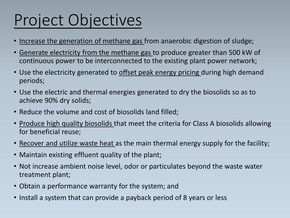
Project Objectives• Increase the generation of methane gas from anaerobic digestion of sludge;
• Generate electricity from the methane gas to produce greater than 500 kW of continuous power to be interconnected to the existing plant power network;
• Use the electricity generated to offset peak energy pricing during high demand periods;
• Use the electric and thermal energies generated to dry the biosolids so as to achieve 90% dry solids;
• Reduce the volume and cost of biosolids land filled;
• Produce high quality biosolids that meet the criteria for Class A biosolids allowing for beneficial reuse;
• Recover and utilize waste heat as the main thermal energy supply for the facility;
• Maintain existing effluent quality of the plant;
• Not increase ambient noise level, odor or particulates beyond the waste water treatment plant;
• Obtain a performance warranty for the system; and
• Install a system that can provide a payback period of 8 years or less
Design Approach• Design/build approach was utilized
• Wisconsin allows for design/build on resource recovery projects
• In the RFP the design/builder was tasked with the following:• Preparation of the design
• Assisting the Kenosha Water Utility (KWU) in obtaining all necessary permits
• Procuring, constructing and installing all components
• Integrating the new system with the existing plant supervisory control and data acquisition (SCADA) network
• Startup and commissioning
• Preparation of operations and maintenance manuals
• Warrantying the system
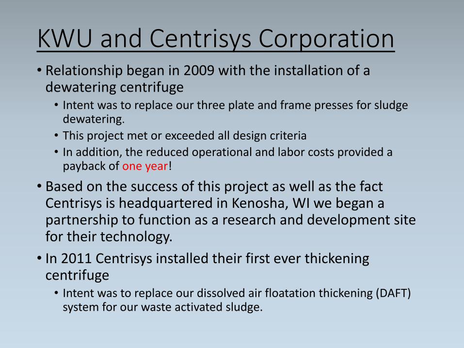
KWU and Centrisys Corporation• Relationship began in 2009 with the installation of a
dewatering centrifuge• Intent was to replace our three plate and frame presses for sludge
dewatering.
• This project met or exceeded all design criteria
• In addition, the reduced operational and labor costs provided a payback of one year!
• Based on the success of this project as well as the fact Centrisys is headquartered in Kenosha, WI we began a partnership to function as a research and development site for their technology.
• In 2011 Centrisys installed their first ever thickening centrifuge • Intent was to replace our dissolved air floatation thickening (DAFT)
system for our waste activated sludge.
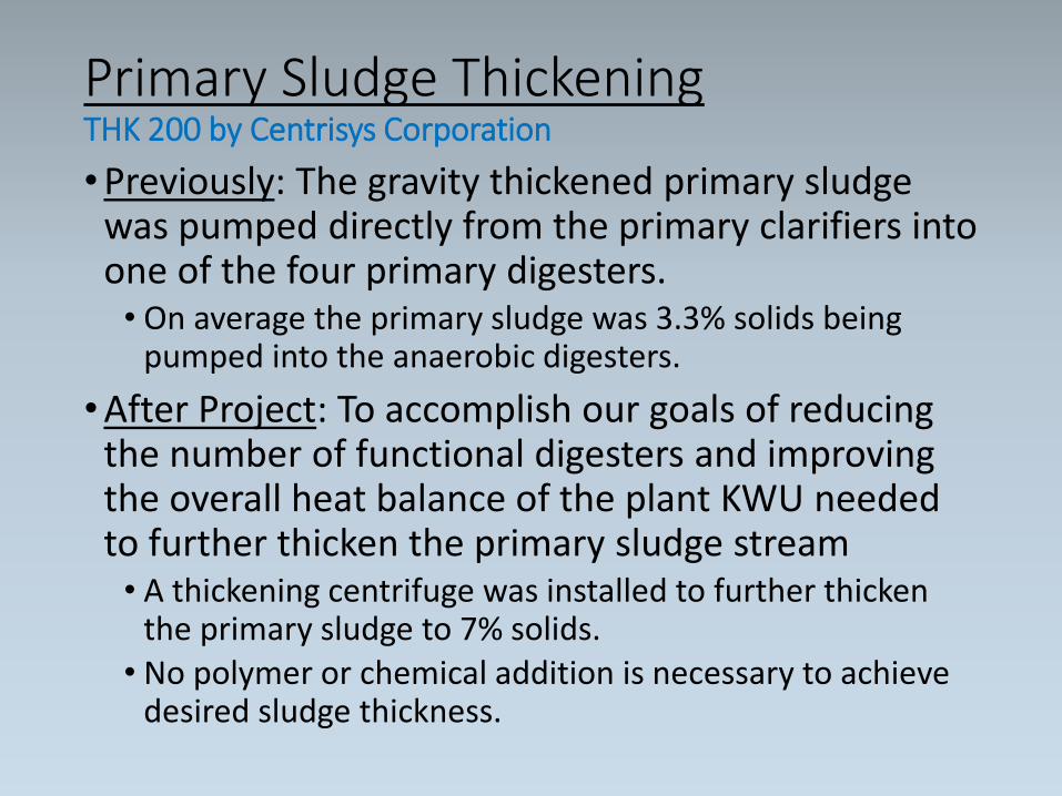
Primary Sludge Thickening THK 200 by Centrisys Corporation
•Previously: The gravity thickened primary sludge was pumped directly from the primary clarifiers into one of the four primary digesters. • On average the primary sludge was 3.3% solids being
pumped into the anaerobic digesters.
•After Project: To accomplish our goals of reducing the number of functional digesters and improving the overall heat balance of the plant KWU needed to further thicken the primary sludge stream• A thickening centrifuge was installed to further thicken
the primary sludge to 7% solids. • No polymer or chemical addition is necessary to achieve
desired sludge thickness.
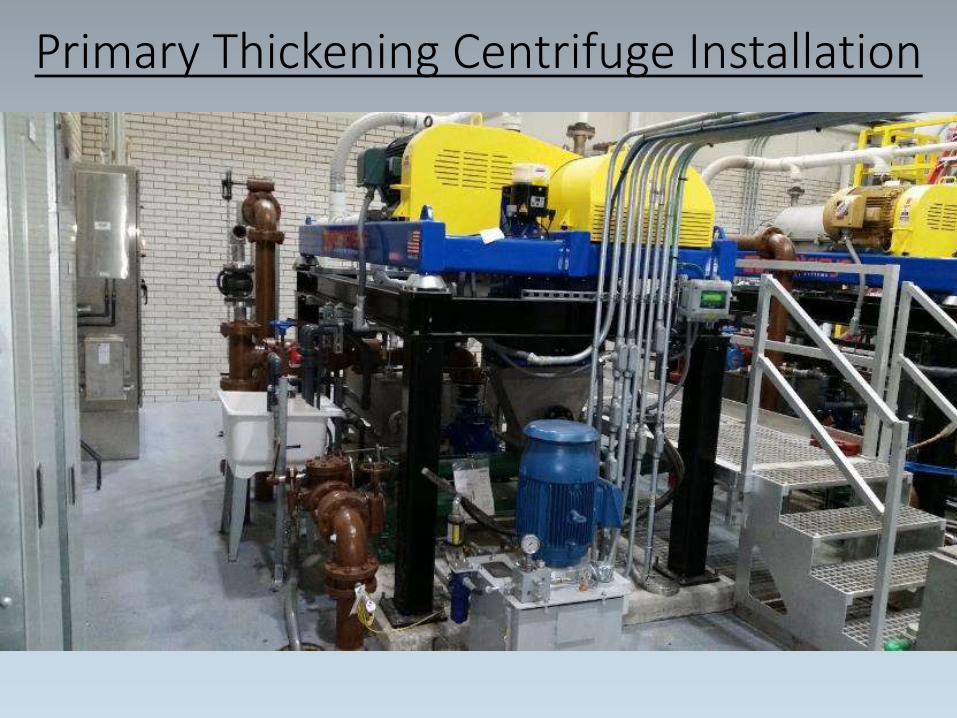
Primary Thickening Centrifuge Installation
WAS Thickening CentrifugeTHK 200 by Centrisys Corporation
•Prior to our partnership: A DAFT system was utilized to thicken the WAS flow stream• The DAFT system thickened the WAS from 1% to 3.5%-
4.0% solids before being pumped into one of the four primary digesters.
•A WAS thickening centrifuge was previously pilot tested and installed in 2011 • Due to downstream limitations the WAS flow stream was
thickened to roughly 5% solids with the thickening centrifuge
• This project allowed us to further thicken the WAS flow stream to 7% solids
• Once again, no polymer or chemical addition is necessary to achieve desired sludge thickness
• The thickened WAS flow is discharged into a thermo-chemical hydrolysis process for further processing.
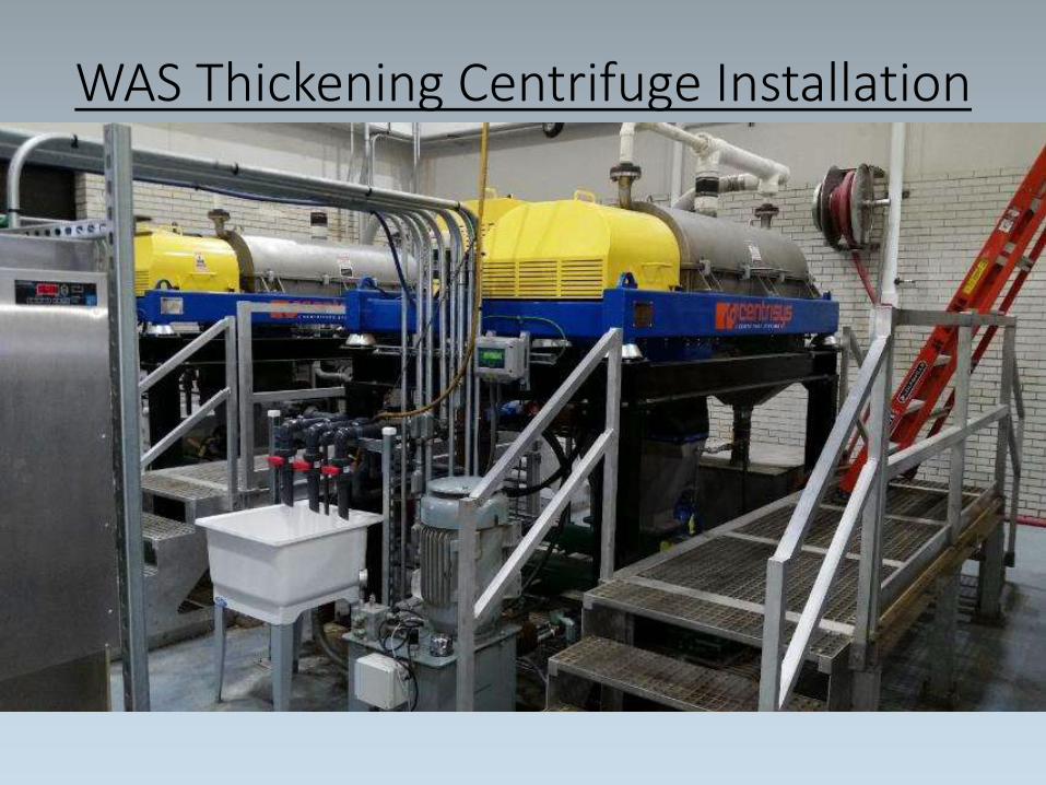
WAS Thickening Centrifuge Installation
Thermo-Chemical Hydrolysis PONDUS by CNP-Technology Water and Biosolids Corporation
Components of Hydrolysis Process:
• “Thermo” – TWAS is heated to 65-70oC (150-160oF)
• “Chemical” – Two liters of caustic soda (50% concentration) is injected per 1 m3 of TWAS
•Detention Time – After the addition of caustic soda and heat, the thickened WAS stream circulates through the reactor for 2 to 2.5 hours.
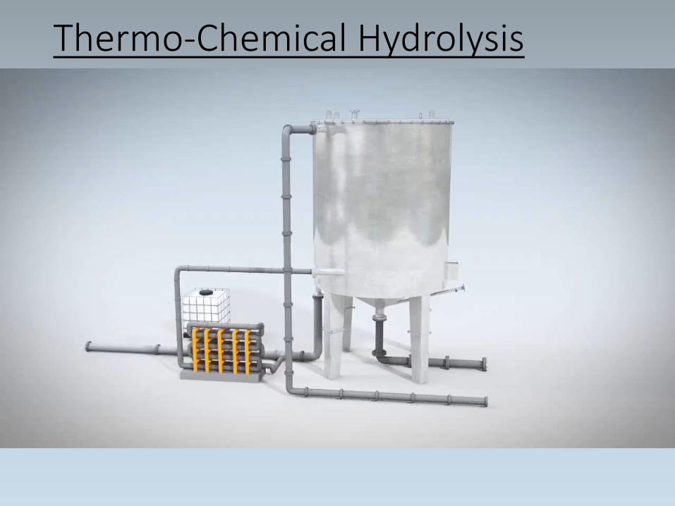
Thermo-Chemical Hydrolysis
Thermo-Chemical Hydrolysis
pH:
•Upon addition of caustic soda pH = 11
•Following hydrolysis process pH = 6.8 to 7.0
•Hydrolysis process breaks down the cell walls and releases internal organic acids which brings the pH of the flow stream back to neutral.
•“Hydrolysis” causes the pH adjustment and therefore no additional chemical addition is necessary.
Thermo-Chemical Hydrolysis
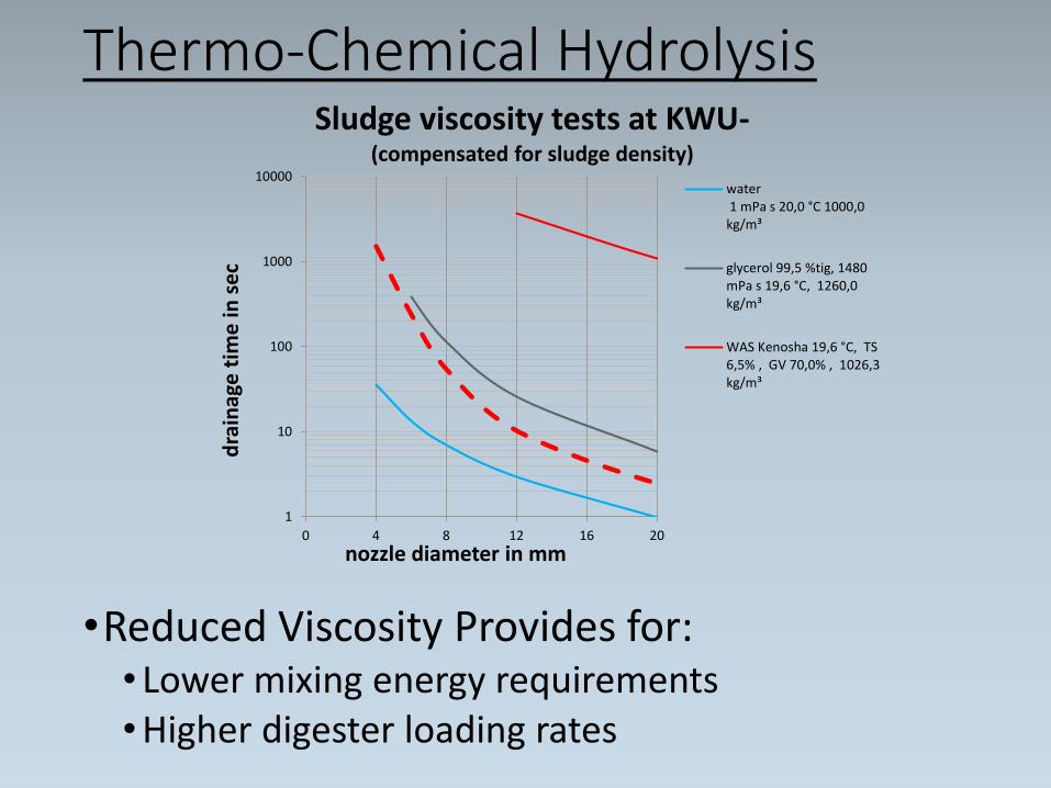
•Reduced Viscosity Provides for:• Lower mixing energy requirements•Higher digester loading rates
1
10
100
1000
10000
0 4 8 12 16 20
dra
inag
e t
ime
in s
ec
nozzle diameter in mm
Sludge viscosity tests at KWU-(compensated for sludge density)
water 1 mPa s 20,0 °C 1000,0kg/m³
glycerol 99,5 %tig, 1480mPa s 19,6 °C, 1260,0kg/m³
WAS Kenosha 19,6 °C, TS6,5% , GV 70,0% , 1026,3kg/m³
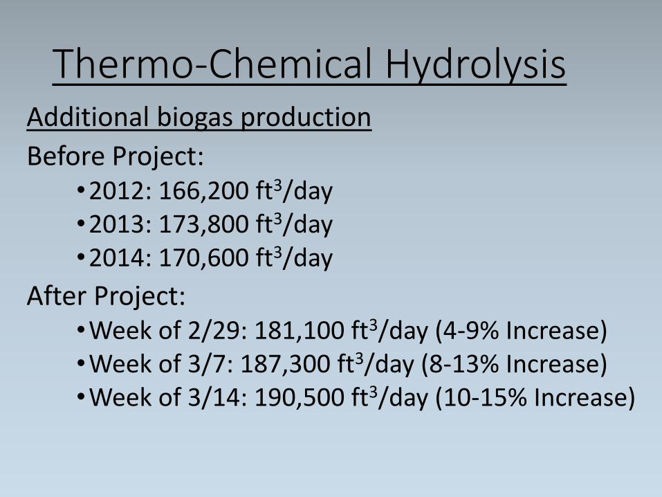
Thermo-Chemical Hydrolysis Additional biogas production
Before Project:•2012: 166,200 ft3/day•2013: 173,800 ft3/day•2014: 170,600 ft3/day
After Project:•Week of 2/29: 181,100 ft3/day (4-9% Increase)•Week of 3/7: 187,300 ft3/day (8-13% Increase)•Week of 3/14: 190,500 ft3/day (10-15% Increase)
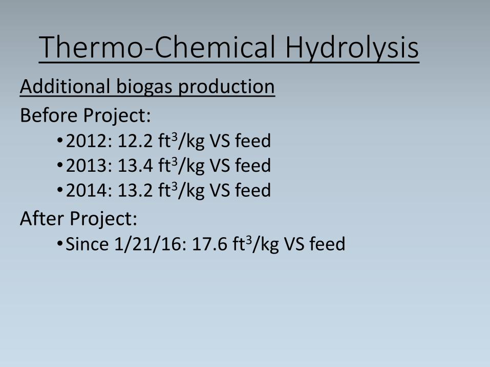
Thermo-Chemical Hydrolysis Additional biogas production
Before Project:•2012: 12.2 ft3/kg VS feed•2013: 13.4 ft3/kg VS feed•2014: 13.2 ft3/kg VS feed
After Project:•Since 1/21/16: 17.6 ft3/kg VS feed
Thermo-Chemical Hydrolysis
Thermal Efficiency
•The blending of hydrolyzed TWAS and unheated thickened primary sludge results in a final temperature of roughly 40oC (100oF) which is ideal for the anaerobic digestion process
•All thermal energy required for the hydrolysis process is transferred into the digesters.
Atmospheric Pressure
•The entire hydrolysis process is completed at atmospheric pressure
Additional Volatile Solids Reduction
Increased Dewaterability of Digested Sludge
Thermo-Chemical Hydrolysis
Reactor:
•Two stage reactor with an outer and inner chamber• Outer Chamber – Recirculates the heated thickened WAS
and caustic soda mixture• Inner Chamber – Acts as a buffer tank from which the
transfer pump draws out of
•Volume - 516 ft3 (3,860 gal)
•Diameter:• Outer chamber – 8.2 ft• Inner chamber – 6.1 ft
•Height - 15.85 ft
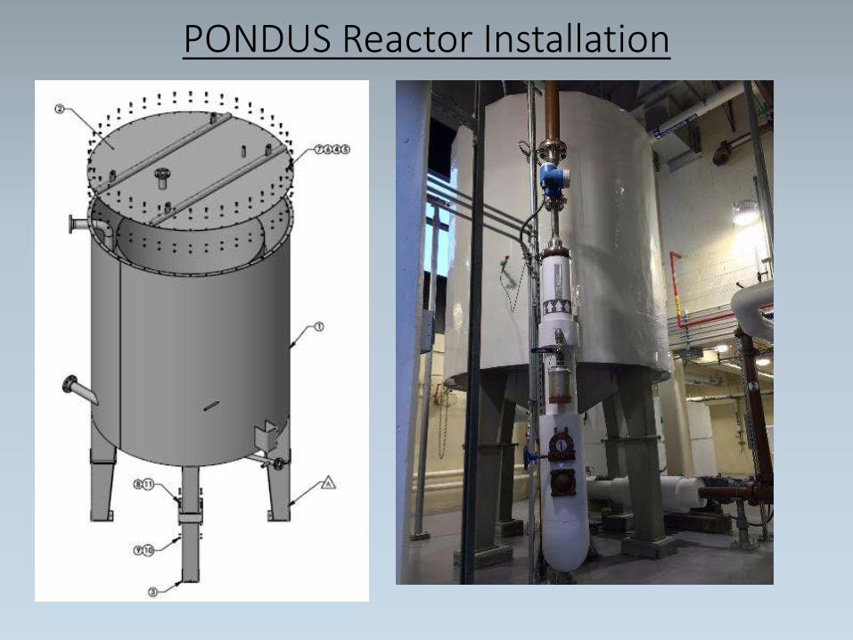
PONDUS Reactor Installation
Thermo-Chemical Hydrolysis
Heat Exchanger:
•Corrugated tube in tube heat exchanger which creates turbulent flow resulting in:• Greater heat transfer capabilities• Reduced fouling of surface area
•Removable ends for easy inspection and maintenance• Thumb screws allow ends to be easily removed for
internal inspection and cleaning.
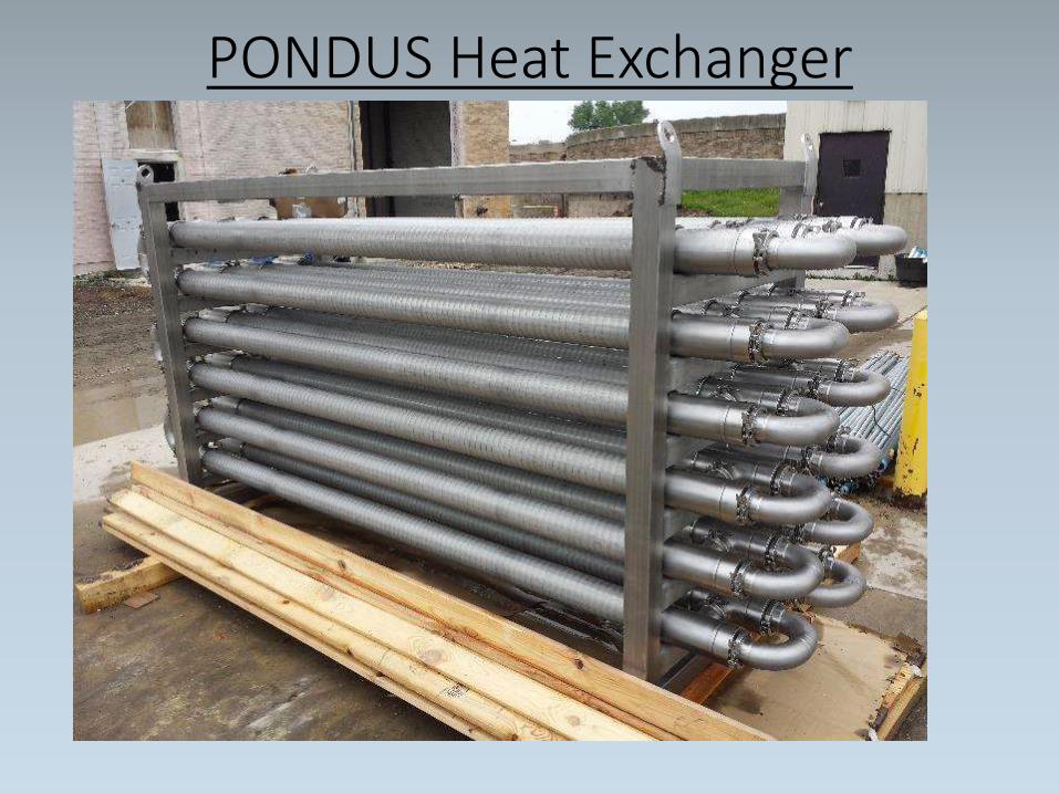
PONDUS Heat Exchanger
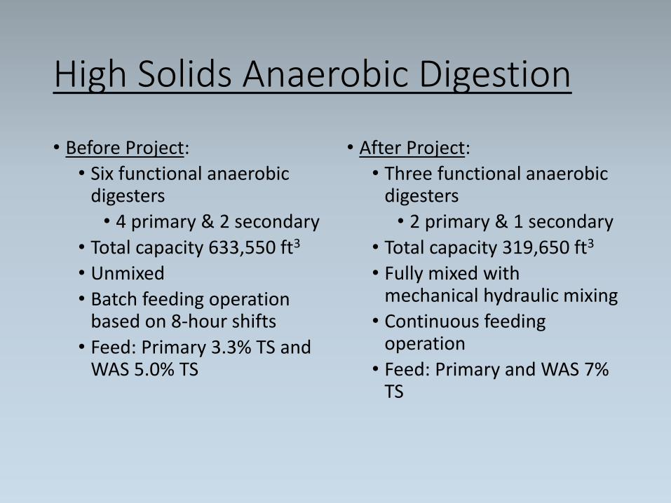
High Solids Anaerobic Digestion
• Before Project:
• Six functional anaerobic digesters
• 4 primary & 2 secondary
• Total capacity 633,550 ft3
• Unmixed
• Batch feeding operation based on 8-hour shifts
• Feed: Primary 3.3% TS and WAS 5.0% TS
• After Project:
• Three functional anaerobic digesters
• 2 primary & 1 secondary
• Total capacity 319,650 ft3
• Fully mixed with mechanical hydraulic mixing
• Continuous feeding operation
• Feed: Primary and WAS 7% TS
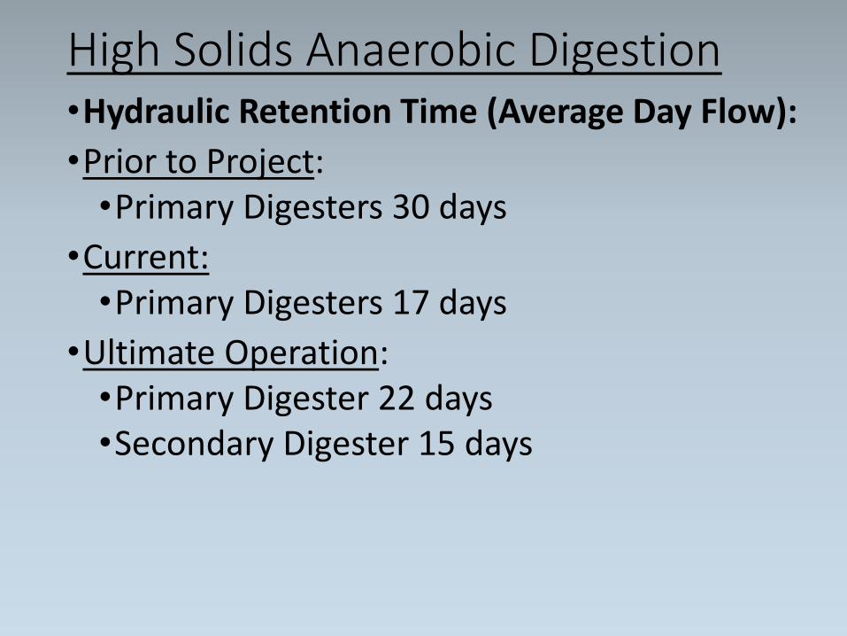
High Solids Anaerobic Digestion•Hydraulic Retention Time (Average Day Flow):
•Prior to Project:•Primary Digesters 30 days
•Current:•Primary Digesters 17 days
•Ultimate Operation:•Primary Digester 22 days•Secondary Digester 15 days
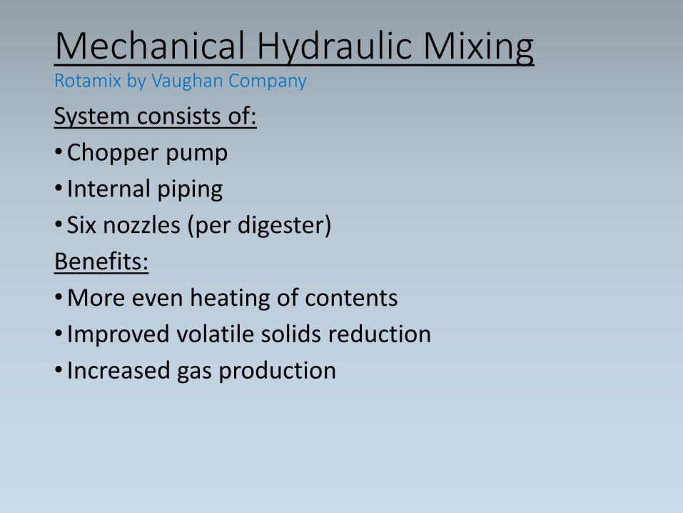
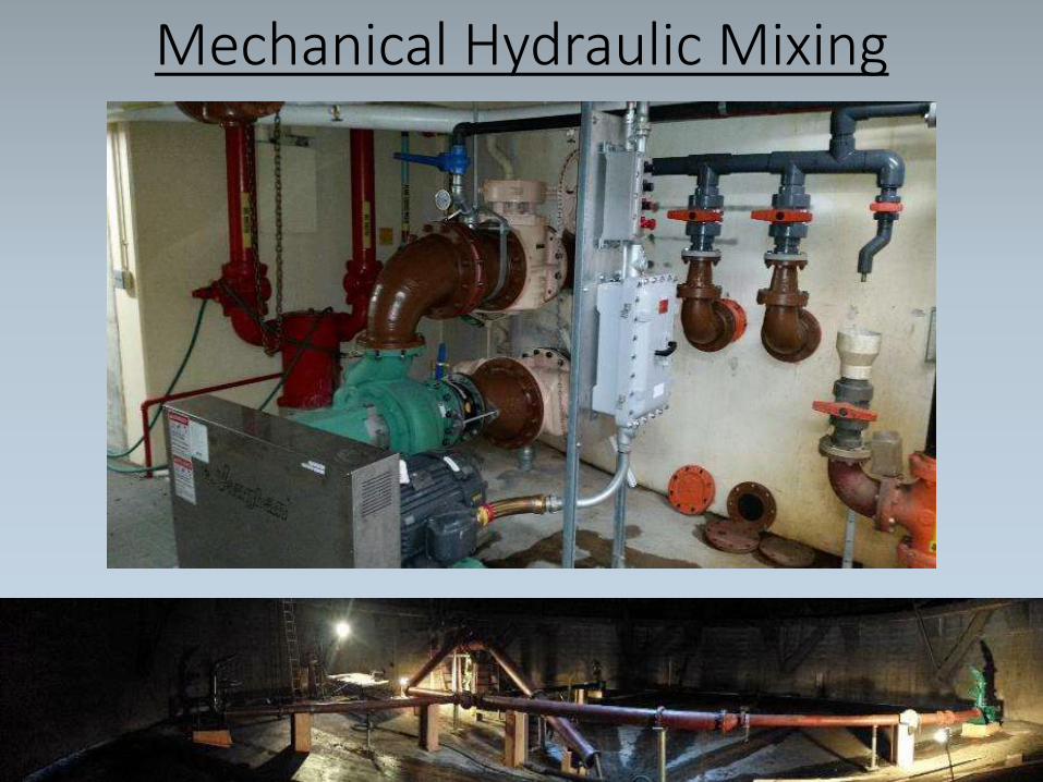
Mechanical Hydraulic Mixing Rotamix by Vaughan Company
System consists of:
•Chopper pump
• Internal piping
•Six nozzles (per digester)
Benefits:
•More even heating of contents
• Improved volatile solids reduction
• Increased gas production
Mechanical Hydraulic Mixing
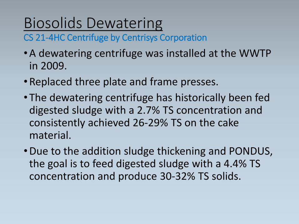
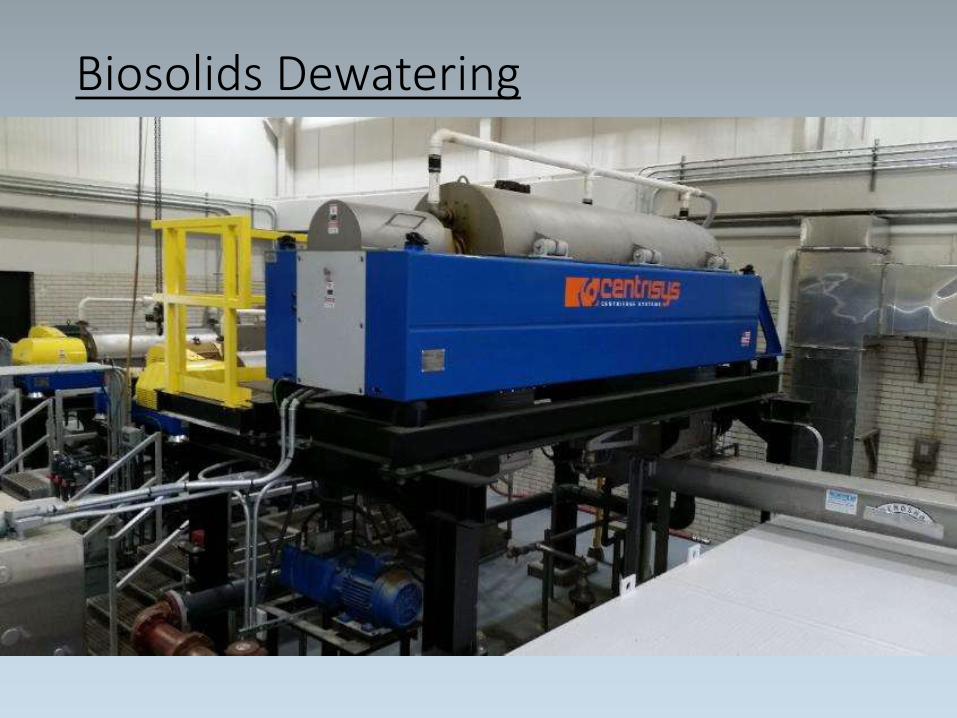
Biosolids Dewatering CS 21-4HC Centrifuge by Centrisys Corporation
•A dewatering centrifuge was installed at the WWTP in 2009.
•Replaced three plate and frame presses.
•The dewatering centrifuge has historically been fed digested sludge with a 2.7% TS concentration and consistently achieved 26-29% TS on the cake material.
•Due to the addition sludge thickening and PONDUS, the goal is to feed digested sludge with a 4.4% TS concentration and produce 30-32% TS solids.
Biosolids Dewatering
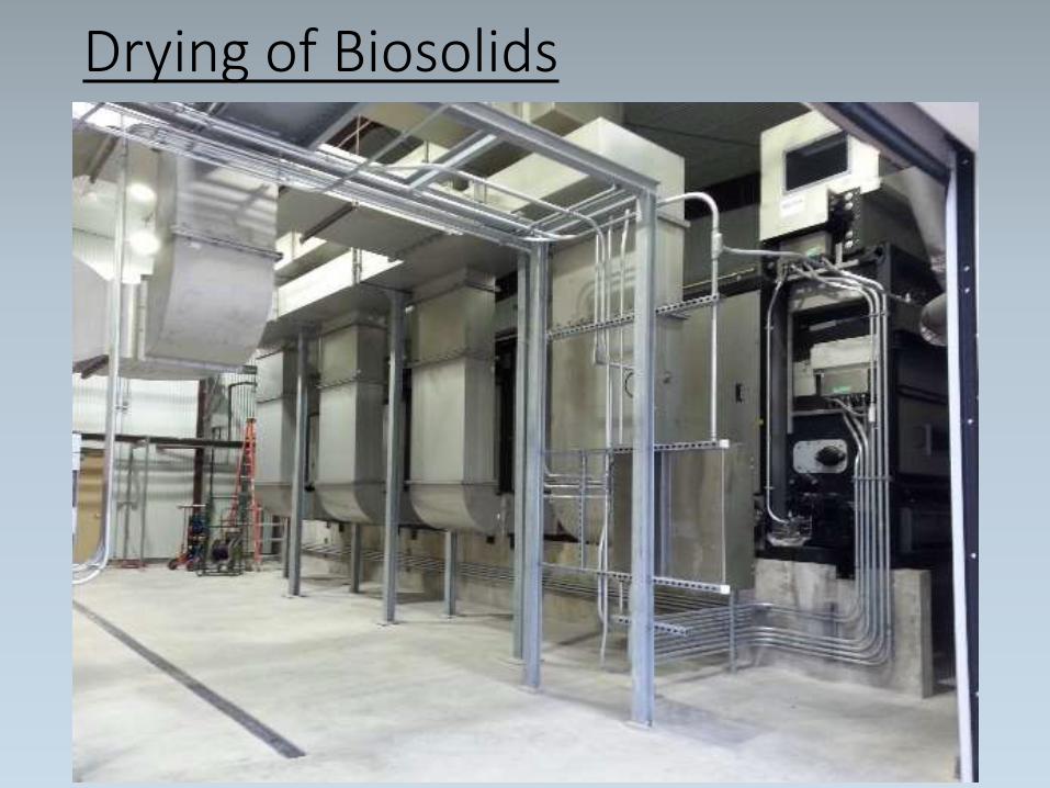
Drying of Biosolids Compact belt dryer by Sulzle-Klein
• Prior to this project the dewatered biosolids were manually loaded into a truck and disposed of at a local landfill.
• After the installation of the new System, the dewatered material leaving the dewatering centrifuge is dried using the recovered heat from the co-generation units as the thermal supply.
• The compact belt dryer achieves all the requirements of Class-A material (temperature, duration, and moisture content) and KWU is currently in the process of getting our final biosolids product re-classified with the Wisconsin Department of Natural Resources.
• The dried product is discharged into a conveyor system and automatically deposited into the bed of a dump truck.
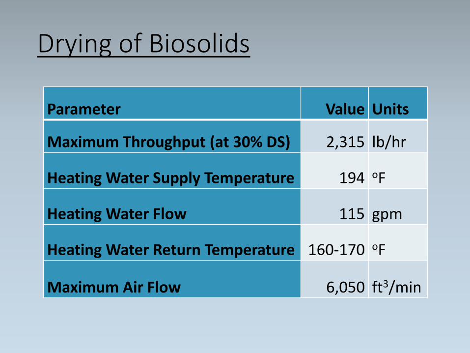
Drying of Biosolids
Parameter Value Units
Maximum Throughput (at 30% DS) 2,315 lb/hr
Heating Water Supply Temperature 194 oF
Heating Water Flow 115 gpm
Heating Water Return Temperature 160-170 oF
Maximum Air Flow 6,050 ft3/min
Drying of Biosolids
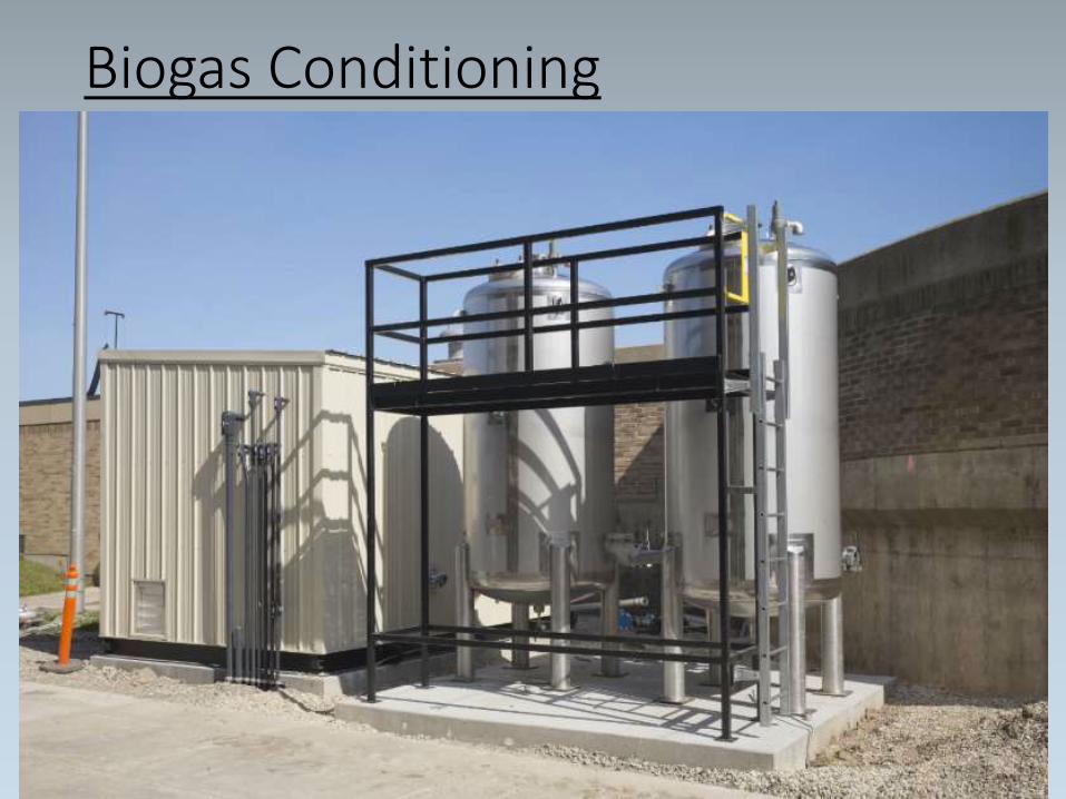
Biogas ConditioningGas conditioning and siloxane removal by Unison Solutions
•Prior to this project the raw biogas produced from the anaerobic digestion process was used as a fuel for our raw water pump engines, hot water boilers or flared to the atmosphere.
•Knowing a more efficient utilization of our biogas would be critical to an effective energy optimization project, a package system capable of removing moisture, particulates and siloxane was incorporated to condition and compress the biogas prior to use as a fuel source in the combined heat and power (CHP) generators.
Biogas Conditioning
Electric & Thermal Energy GenerationCHP Generators by Kraft Power
•Prior to this project the electricity needed to run the equipment at the WWTP was purchased exclusively from the local utility.
• In addition, any heat needed for our operations were provided by our boilers using either natural gas or biogas as their fuel source.
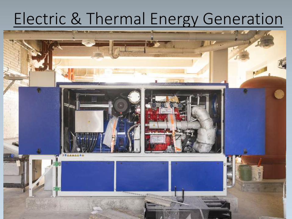
•To better utilize the biogas produced during the digestion process we installed two combined heat and power (CHP) generators.
•These generators utilize the methane produced in the anaerobic digestion process as a fuel source to generate electricity as well as thermal energy.
Electric & Thermal Energy Generation
•The CHP units are each capable of producing:• 330 kW of electrical energy• 422 kW of thermal energy.
•The electricity produced will power the new system as well as supply the excess electricity to the main plant power network for beneficial use elsewhere throughout the plant.
•The thermal energy will be utilized by the PONDUS system, the compact belt dryer and the central WWTP heating loop.
Electric & Thermal Energy Generation
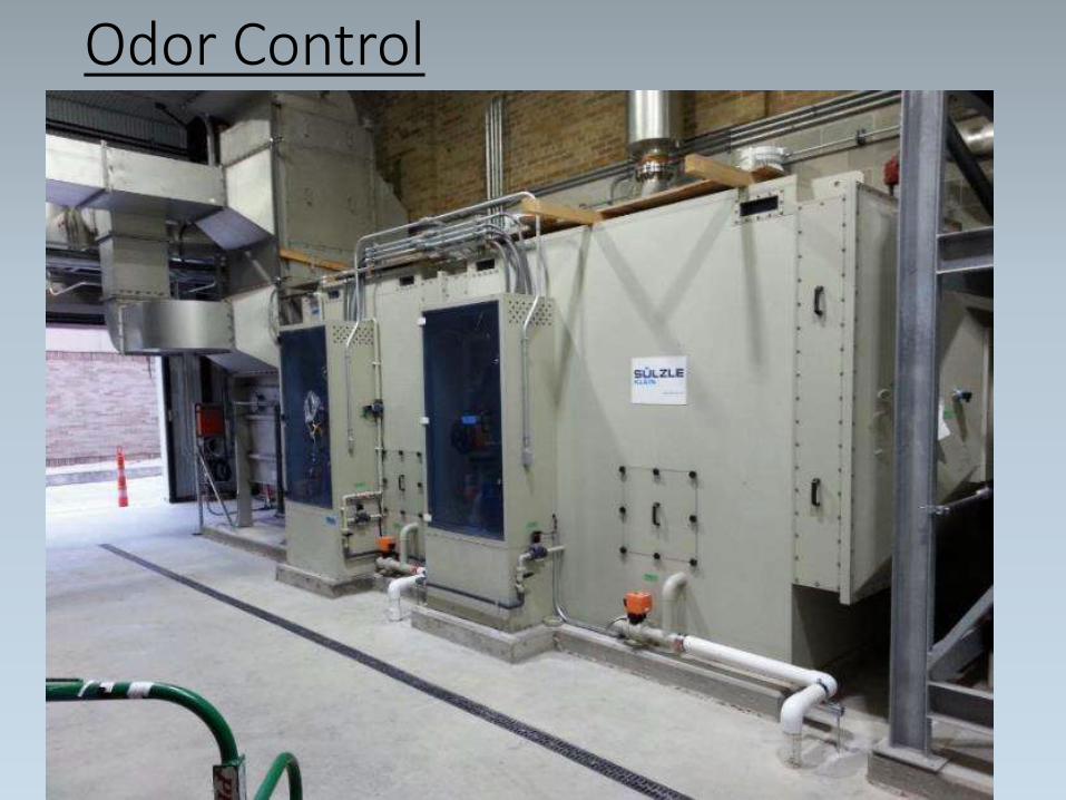
Odor Control KWT 1000/1300 by Sulzle-Klein
• Due to the wastewater plant being located adjacent to a residential neighborhood odor control was also incorporated into the design.
• A robust odor control system which utilizes water, sulfuric acid and caustic soda was installed to treat the exhaust air from the belt dryer as well as the aspiration air from the primary sludge mix tank, blended sludge mix tank, PONDUS reactor, primary sludge thickening centrifuge, WAS thickening centrifuge, dewatering centrifuge and dryer feed pump.
• Water is utilized to cool the exhaust and remove particulates from the air.
• The sulfuric acid is used to reduce or eliminate the ammonia odors from the biosolids process.
• Caustic soda is used to reduce or eliminate the odors from sulfur compounds such as mercaptans in the exhaust stream
Odor Control
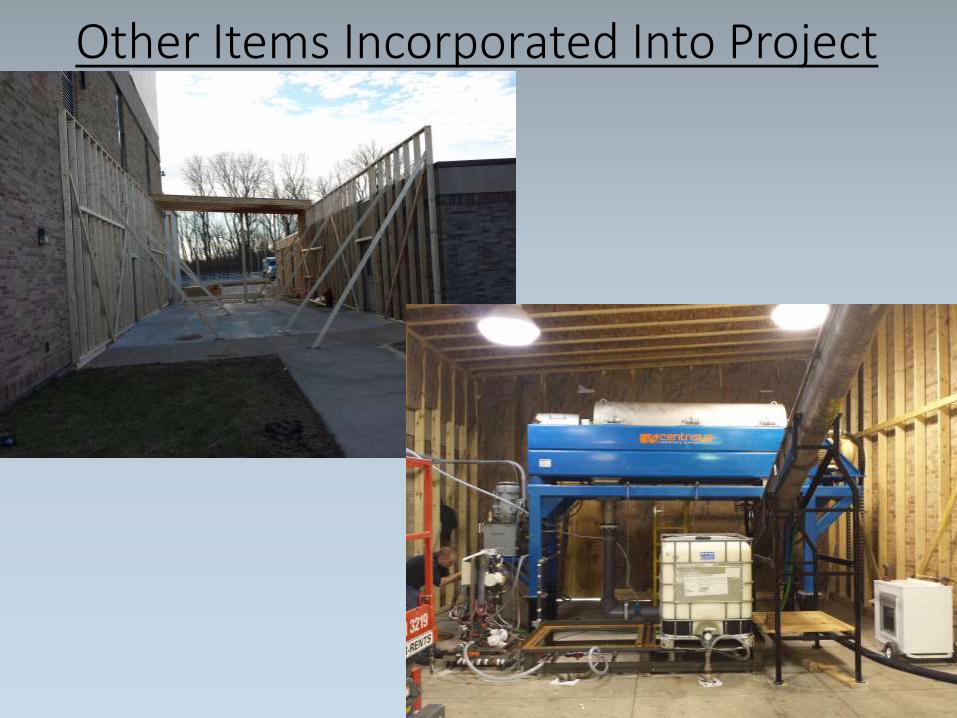
Other Items Incorporated Into Project
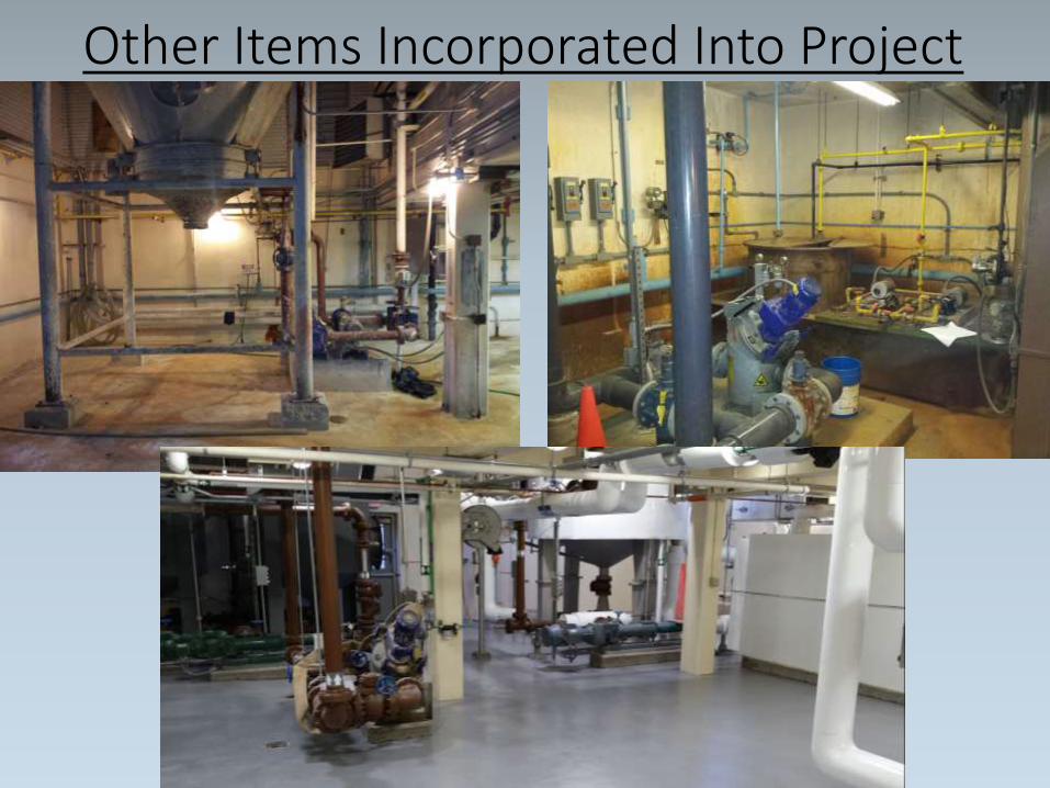
Other Items Incorporated Into Project
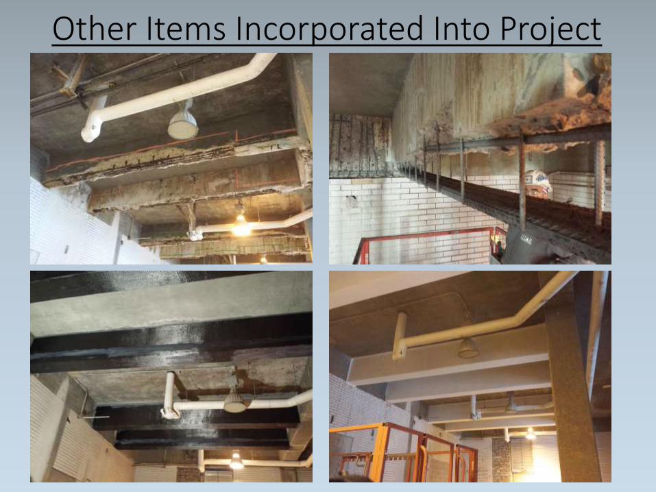
Other Items Incorporated Into Project
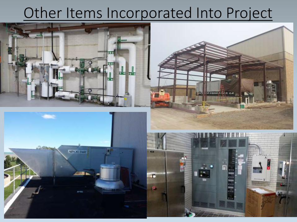
Other Items Incorporated Into Project

Estimated Added Value
Criteria Daily Annual Unit Cost Unit Annual Savings
On-Peak Electricity (kWh) 4,536 1,655,640 $0.07660 per kWh $126,822
Off-Peak Electricity (kWh) 8,064 2,943,360 $0.05238 per kWh $154,173
Electric Demand (kW) 525 6,300 $12.65 per kW $79,695
Electrical Total $360,690
Cake Sludge (wet tons) 25 9,249 $38.01 per ton $351,554
Disposal Total $351,554
TOTAL Savings $712,244
Grant from Local Utility
•Due to the nature of the project KWU was awarded over $500,000 in grants for implementing the new biosolids process from Focus on Energy.
•The installation of the thermo-chemical hydrolysis system, co-generation units, and LED lighting all qualified for the largest grant this organization can award for a single project.
Conclusion
Through innovative thinking KWU was able to:•Become more energy efficient•Less reliant on purchased electrical and thermal energy•Reduce operating costs

Questions?Curtis Czarnecki, P.E.
Director of Engineering Services
Kenosha Water Utility
4401 Green Bay Road
Kenosha, WI 53144
Phone (262)653-4306
Email: [email protected]


