Chapter 5 Impact Craters Impacts are one of the most important processes in controlling planetary evolution. In addition to shaping the surfaces of the terrestrial planets, they also constituted an important source of heat in the early stages of planetary evolution. Impacts also may have catastrophic consequences on geological, atmospheric and even biological evolution. The importance of impacts had long been overlooked in part because of the tendency of geologic thought to favor slow change rather than short term catastrophic events as significant contributors to evolution. On the Moon, the impact origin of nearly all craters was not established until the Apollo era. A long-held myth was that lunar craters could not be due to impact because they were circular. In fact we shall see from the mechanics of shock wave propagation that this is to be expected in most instances. To place the impact process in the proper context, we begin with a physical description via the physics of propagation of stress waves and the partitioning of energy between a projectile and target. We then discuss crater morphology as it relates to the mechanics of the impact process and the character and evolution of the impacted substrate. Finally we discuss the use of crater statistics as a means of determining the relative ages of planetary surfaces. 5.1 Impact Mechanics 5–1
Transcript
Chapter
5 Impact Craters
Impacts are one of the most important processes in controlling planetary evolution.In addition to shaping the surfaces of the terrestrial planets, they also constituted animportant source of heat in the early stages of planetary evolution. Impacts also mayhave catastrophic consequences on geological, atmospheric and even biological evolution.The importance of impacts had long been overlooked in part because of the tendencyof geologic thought to favor slow change rather than short term catastrophic events assignificant contributors to evolution. On the Moon, the impact origin of nearly all craterswas not established until the Apollo era. A long-held myth was that lunar craters couldnot be due to impact because they were circular. In fact we shall see from the mechanicsof shock wave propagation that this is to be expected in most instances.
To place the impact process in the proper context, we begin with a physical descriptionvia the physics of propagation of stress waves and the partitioning of energy between aprojectile and target. We then discuss crater morphology as it relates to the mechanics ofthe impact process and the character and evolution of the impacted substrate. Finally wediscuss the use of crater statistics as a means of determining the relative ages of planetarysurfaces.
5.1 Impact Mechanics
5–1
The clearest exposition of the physics of the impact processes is presented in H.J.Melosh’s fine book Impact Cratering: A Geological Process. The following discussionfollows the conventions in that text and the reader is encouraged to follow up with thatreference for further details.
We pursue a first principles approach beginning with pressure waves in fluids, stresswaves in elastic solids, stress waves in which permanent deformation of the target mediumoccurs, and finally shock waves.
5.1.1 Waves in a Fluid Medium
An impact on a surface compresses the surface and energy is distributed in the mediumvia waves with energies that are proportional to the impactor speed and energy, and onthe material properties of the target medium. An exact treatment can’t be done, but it istractable to look at an impact into a semi-infinite medium with an initial particle velocityequal to zero. The simplest useful physical description of the process is a one-dimensionalpressure or acoustic wave in a strengthless fluid. This wave equation has both temporaland spatial dependences and the solutions describe the propagation of wave trains thattravel at constant speed. The expression can be written
∂2P
∂t2= c2ω
∂2P
∂x2(1)
where P is pressure, x is the distance along the direction of propagation, t is time and
cω =
√Ko
ρo(2)
is the wave speed, for which Ko is the bulk modulus measured at the zero pressureisentrope (= 1/compressibility) and ρo is the uncompressed density. In this arrangementpressure relates to particle velocity ul by
P = ρoulcω. (3)
The PDEs that describe the wave propagation are linear, and so pressure waves can besuperposed. The stress state in the medium is fully characterized by the pressure and thereare no differential stresses.
The energy density in the wave is
E =12u2l − P
dρ
ρ2o
, (4)
where the first term is the kinetic energy per unit mass and the second is the work perunit mass (=PdV where V is volume) done in compressing the medium integrated overthe wave propagation time. For this simple situation the two contributions are equal.
5.1.2 Stress Waves in an Elastic Medium
5–2
Stress waves that propagate through a homogeneous elastic medium are more com-plicated than pressure waves in a fluid because elastic materials can support differentialstresses. There are two types of stress waves in homogeneous elastic media – longitudi-nal and transverse. Longitudinal waves are equivalent to the pressure waves in a fluid.Transverse waves have no analog in fluids and arise because solids, in addition to resist-ing compression, also resist changes in shape (i.e., distortion). Resistance is related to theshear modulus (µ), which is always smaller than the bulk modulus, so the transverse wavespropagate more slowly than the longitudinal waves. The transverse waves propagate in adirection perpendicular to that of the longitudinal waves.
Elastic waves are also described by linear PDEs, however, unlike the case of pressurewaves in a fluid, the pressure alone does not fully describe the stress state. In one dimensionthe equations of motion for longitudinal and transverse waves can be written
∂2ul∂t2
= c2l∂2ul∂x2
(5a)
and∂2ut∂t2
= c2t∂2ut∂x2
, (5b)
where ul is the particle velocity in a longitudinal wave that propagates at speed cl = [(Ko+4/3µ)/ρo]1/2, ut represents either component of orthogonal transverse particle velocitycomponents that both propagate at speed ct = (µ/ρo)1/2. The propagation velocitiesdepend on the bulk and shear moduli. Longitudinal waves travel faster than pressure wavesin a fluid because the elastic materials resistance to distortion augments the resistance tocompression, which is controlled by Ko. The transverse wave speed depends only on theshear modulus because the transverse wave motion does not cause a change in the volumeof the material that it passes through.
Unlike the situation for a fluid, the stress state in a solid must be described by all ofthe stress components and not just the pressure. The full stress tensor with both normaland shear components is relevant. The stresses can be written
σl = ρoulcl (6a)
and
σp =(
ν
1− ν
)σl, (6b)
where σl is the longitudinal stress, and σp is the stress component perpendicular to thedirection of propagation. (We use engineering convention where tension is positive). Theparameter ν is Poisson’s ratio which indicates the amount of lateral contraction thatoccurs for a given longitudinal extension. The stress in a transverse wave is pure shear,with the only non-zero components of the stress tensor being in the off-diagonal. The shearstress τ is
τ = ρoutct. (7)
Stresses associated with transverse waves are lower than in longitudinal waves because theparticle velocities are lower. Like pressure waves in a fluid, the energy density in either
5–3
wave type is related to the sum of the mean kinetic and distortional energies integratedover the time of wave propagation. Transverse waves are probably not too important inthe cratering process because the strength of these waves is limited by the shear strengthof the target. In contrast the longitudinal wave strength has no limit.
5.1.3 The Importance of the Free Surface and Internal Interfaces
Impacts on planetary surfaces and their stress waves will propagate into the subsurfacewhich in many circumstances may contain interfaces between layers with differing mechan-ical properties. The interaction of impact-generated stress waves with free surfaces andinternal interfaces generates new waves, and the interactions can be described exactly in aphysical sense for linear waves such as discussed so far. Interactions of waves at interfacesare easy to describe. Layers of different materials may have different material properties,indicating that waves will propagate at different speeds and experience different levels ofstress. However, velocities and stresses at the interfaces of materials must be continuous.To conserve energy more waves must be generated.
At a free surface, however, normal and shear stresses cannot be supported. When awave strikes it, another wave must be generated that maintains the normal stress at thezero level. If a compressional wave impinges on a free surface, it must therefore generatea corresponding tensional wave such that the sum of the longitudinal stresses (Equation(6a)) vanish at the free surface. The compressional and tensional waves overlap for ashort period of time resulting in a complex near-surface stress field. But while the stressesvanish at the surface, the velocities do not. Because the waves are linear we may addtheir velocities during the time during which they overlap. Because the tensional wave isopposite in sign and moves in the opposite direction of the compressional wave, there is adouble negative and the wave speed at the free surface equals 2ul. This is known as thevelocity doubling rule.
Velocity doubling is responsible for producing spalling of the surface. Spalls are targetfragments that break off at the free surface and have a velocity of twice that of the particlevelocity in the compressed medium. Spalls do not remove a large amount of material in animpact but they have the capability to eject some material at speeds that exceed a planetsescape velocity. Hence may samples of planetary surfaces perhaps be ejected into space.
5.1.4 The Hugoniot Elastic Limit
The stress and particle velocities in elastic waves increase as the intensity of the sourceincreases. Eventually the stresses will exceed the strength of the material and plastic orirreversible work will be done in the target medium. Solids can resist almost arbitrarilylarge compressive stresses, however, their ability to resist stress differences is limited. Thesestress differences occur because waves generate both longitudinal and transverse stresses.The longitudinal stress is a factor (1 − ν)/ν greater than the stress generated by thetransverse wave. So as the strength of the wave increases the absolute difference betweenthe stresses also increases. Eventually the stress difference will reach a yield stress inwhich permanent deformation of the medium will occur. The medium deforms by plasticflow and there is little subsequent increase in the stress difference as the medium cannotsupport it.
5–4
Consider the failure of a typical rock. At (relatively) low stresses (<2 GPa) the shearstress
τ = −σl − σp2
(8)
and mean pressure
P = −σl + 2σp3
(9)
follow a linear relationship defined by a Coulomb friction law. At higher pressuresstrength is nearly constant and failure is characterized by plastic distortion or ductile flow.The slope of the failure envelope in the Coulomb portion of the curve (30◦ − 45◦ for mostrocks) rises more steeply than the line representing the stress in a longitudinal elastic wave,which begins at the origin and is 3(1 − 2ν)/2(1 − ν), approximately 30◦ for ν = 0.25, atypical value for rocks. So failure doesn’t occur at low stresses. But the failure envelopeeventually flattens out and the elastic stress trajectory intersects it at τ = Y/2. Thelongitudinal stress at this point is
σl = −σHEL = − 1− ν(1− 2ν)Y
(10)
where σHEL is the Hugoniot Elastic Limit or HEL. Beyond this limit the maximumshear stress τ remains constant at Y/2 as P increases. Both longitudinal and transversewaves propagate in a manner such that −(σl − σp)/2 always equals Y/2. For very strongwaves this stress difference is miniscule compared to the mean stress and can be neglected.The wave can be approximated as a strong pressure wave. The propagation speed of awave after the HEL has been exceeded drops significantly. For an elastic wave below theHEL both shear and bulk moduli contribute to cl. Beyond the HEL, however, only thebulk modulus contributes significantly and the speed drops to nearly the bulk wave speed.The bulk modulus increases with pressure, and so the wave speed begins to rise againin high pressure waves. In extremely strong stress waves, called shock waves, the wavepropagation speed may exceed cl.
5.1.5 The Rankine-Hugoniot Equations
Shock waves travel faster than elastic waves in an uncompressed medium and aretherefore supersonic. They ’outrun’ elastic waves and add the energy of the elastic wavesto their own. Shock fronts tend to be abrupt, and they are most often represented in amathematical sense as discontinuities in pressure, particle velocity, density and pressure,which is convenient though not strictly true. The basic equations that describe abruptshock fronts were first derived by R.P. Hugoniot in 1887 and involve the pressures Po andP in front of and behind a shock front, the particle velocity u behind the shock front, theshock velocity U , the compressed and uncompressed densities ρ and ρo and the internalenergies or energies per unit mass Eo and E on either side of the shock front. The equationsderive from the conservation of mass, momentum and energy across the discontinuity.
Consider a block of material through which a shock wave passes. At time t the blockcan be divided into a part, with length ls through which the shock wave has passed andanother, lu through which it hasn’t. At a later time t′ the shock wave has propagated a
5–5
distance U(t′ − t) and the particle velocity has progressed u(t′ − t). The lengths of theunshocked (l′u) and shocked (l′s) regions are
l′u = lu − U(t′ − t) (11a)
andl′s = ls + U(t′ − t)− u(t′ − t). (11b)
The mass contained in the unshocked part of the block at time t is the product of its volumeand density ρoluA, where A is area, while the mass in the shocked section is similarly ρlsA.Mass conservation dictates that we equate these quantities:
ρlsA+ ρoluA = ρl′sA+ ρol′uA (12)
By canceling A and substituting (11) yields
ρ(U − u)(t′ − t)− ρoU(t′ − t) = 0 (13)
which, with further canceling, yields the first Hugoniot equation:
ρ(U − u) = ρoU, (14)
which relates the shock and particle velocities to the densities in the medium before andafter shock wave passage.
The second equation comes from momentum conservation. Because the pressure P onthe shocked end of the block is greater than the pressure Po on the unshocked end thereis a net force F = (P − Po)A that acts in the direction of shock wave propagation. Themomentum in the material at time t is ρlsupA, which differs from that in the materialat time t′ (ρl′supA) at the applied force over the time interval F (t′ − t). The momentumbalance requires
ρl′suA− ρlsu = (P − Po)A(t′ − t). (15)
By canceling and substituting (11b) we obtain
ρ(U − u)u = (P − Po) (16)
Using (14) we arrange to get the second Hugoniot equation
P − Po = ρoUu, (17)
which relates velocities to the pressures ahead of and behind the shock wave.The final expression that we seek derives from conservation of energy and describes
the internal energy of shocked material. As for momentum, the energy in the systemchanges between times t and t′ because the passage of the shock wave does work on thesystem. Because the end of the unshocked block has a zero displacement the increase inenergy during the time interval is
PAu(t′ − t) (18)
5–6
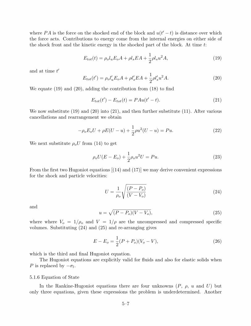
where PA is the force on the shocked end of the block and u(t′ − t) is distance over whichthe force acts. Contributions to energy come from the internal energies on either side ofthe shock front and the kinetic energy in the shocked part of the block. At time t:
Etot(t) = ρoluEoA+ ρlsEA+12ρlsu
2A, (19)
and at time t′
Etot(t′) = ρol′uEoA+ ρl′sEA+
12ρl′su
2A. (20)
We equate (19) and (20), adding the contribution from (18) to find
Etot(t′)− Etot(t) = PAu(t′ − t). (21)
We now substitute (19) and (20) into (21), and then further substitute (11). After variouscancellations and rearrangement we obtain
−ρoEoU + ρE(U − u) +12ρu2(U − u) = Pu. (22)
We next substitute ρoU from (14) to get
ρoU(E − Eo) +12ρou
2U = Pu. (23)
From the first two Hugoniot equations [(14) and (17)] we may derive convenient expressionsfor the shock and particle velocities:
U =1ρo
√(P − Po)(V − Vo)
(24)
andu =
√(P − Po)(V − Vo), (25)
where where Vo = 1/ρo and V = 1/ρ are the uncompressed and compressed specificvolumes. Substituting (24) and (25) and re-arranging gives
E − Eo =12
(P + Po)(Vo − V ), (26)
which is the third and final Hugoniot equation.The Hugoniot equations are explicitly valid for fluids and also for elastic solids when
P is replaced by −σl.
5.1.6 Equation of State
In the Rankine-Hugoniot equations there are four unknowns (P , ρ, u and U) butonly three equations, given these expressions the problem is underdetermined. Another
5–7
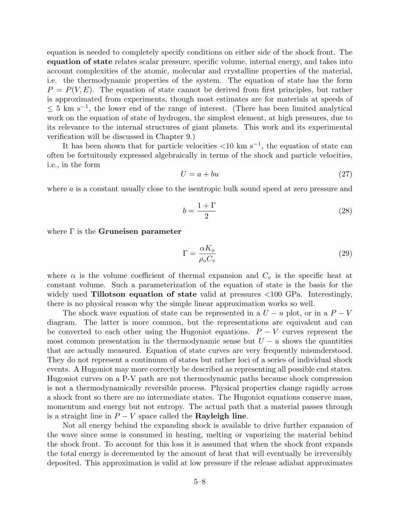
equation is needed to completely specify conditions on either side of the shock front. Theequation of state relates scalar pressure, specific volume, internal energy, and takes intoaccount complexities of the atomic, molecular and crystalline properties of the material,i.e. the thermodynamic properties of the system. The equation of state has the formP = P (V,E). The equation of state cannot be derived from first principles, but ratheris approximated from experiments, though most estimates are for materials at speeds of≤ 5 km s−1, the lower end of the range of interest. (There has been limited analyticalwork on the equation of state of hydrogen, the simplest element, at high pressures, due toits relevance to the internal structures of giant planets. This work and its experimentalverification will be discussed in Chapter 9.)
It has been shown that for particle velocities <10 km s−1, the equation of state canoften be fortuitously expressed algebraically in terms of the shock and particle velocities,i.e., in the form
U = a+ bu (27)
where a is a constant usually close to the isentropic bulk sound speed at zero pressure and
b =1 + Γ
2(28)
where Γ is the Gruneisen parameter
Γ =αKo
ρoCv(29)
where α is the volume coefficient of thermal expansion and Cv is the specific heat atconstant volume. Such a parameterization of the equation of state is the basis for thewidely used Tillotson equation of state valid at pressures <100 GPa. Interestingly,there is no physical reason why the simple linear approximation works so well.
The shock wave equation of state can be represented in a U − u plot, or in a P − Vdiagram. The latter is more common, but the representations are equivalent and canbe converted to each other using the Hugoniot equations. P − V curves represent themost common presentation in the thermodynamic sense but U − u shows the quantitiesthat are actually measured. Equation of state curves are very frequently misunderstood.They do not represent a continuum of states but rather loci of a series of individual shockevents. A Hugoniot may more correctly be described as representing all possible end states.Hugoniot curves on a P-V path are not thermodynamic paths because shock compressionis not a thermodynamically reversible process. Physical properties change rapidly acrossa shock front so there are no intermediate states. The Hugoniot equations conserve mass,momentum and energy but not entropy. The actual path that a material passes throughis a straight line in P − V space called the Rayleigh line.
Not all energy behind the expanding shock is available to drive further expansion ofthe wave since some is consumed in heating, melting or vaporizing the material behindthe shock front. To account for this loss it is assumed that when the shock front expandsthe total energy is decremented by the amount of heat that will eventually be irreversiblydeposited. This approximation is valid at low pressure if the release adiabat approximates
5–8
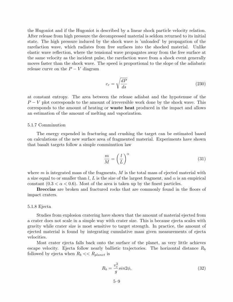
the Hugoniot and if the Hugoniot is described by a linear shock particle velocity relation.After release from high pressure the decompressed material is seldom returned to its initialstate. The high pressure induced by the shock wave is ’unloaded’ by propagation of therarefaction wave, which radiates from free surfaces into the shocked material. Unlikeelastic wave reflection, where the tensional wave propagates away from the free surface atthe same velocity as the incident pulse, the rarefaction wave from a shock event generallymoves faster than the shock wave. The speed is proportional to the slope of the adiabaticrelease curve on the P − V diagram
cr =
√dP
ds(230)
at constant entropy. The area between the release adiabat and the hypotenuse of theP − V plot corresponds to the amount of irreversible work done by the shock wave. Thiscorresponds to the amount of heating or waste heat produced in the impact and allowsan estimation of the amount of melting and vaporization.
5.1.7 Comminution
The energy expended in fracturing and crushing the target can be estimated basedon calculations of the new surface area of fragmented material. Experiments have shownthat basalt targets follow a simple comminution law
m
M=(l
L
)α(31)
where m is integrated mass of the fragments, M is the total mass of ejected material witha size equal to or smaller than l, L is the size of the largest fragment, and α is an empiricalconstant (0.3 < α < 0.6). Most of the area is taken up by the finest particles.
Breccias are broken and fractured rocks that are commonly found in the floors ofimpact craters.
5.1.8 Ejecta
Studies from explosion cratering have shown that the amount of material ejected froma crater does not scale in a simple way with crater size. This is because ejecta scales withgravity while crater size is most sensitive to target strength. In practice, the amount ofejected material is found by integrating cumulative mass given measurements of ejectavelocities.
Most crater ejecta falls back onto the surface of the planet, as very little achievesescape velocity. Ejecta follow nearly ballistic trajectories. The horizontal distance Rbfollowed by ejecta when Rb << Rplanet is
Rb =v2e
gsin2φ, (32)
5–9
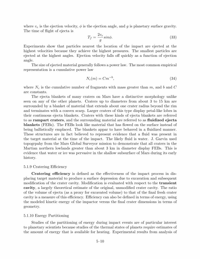
where ve is the ejection velocity, φ is the ejection angle, and g is planetary surface gravity.The time of flight of ejecta is
Tf =2vegsinφ. (33)
Experiments show that particles nearest the location of the impact are ejected at thehighest velocities because they achieve the highest pressures. The smallest particles areejected at the highest angles. Ejection velocity falls off quickly as a function of ejectionangle.
The size of ejected material generally follows a power law. The most common empiricalrepresentation is a cumulative power law
Nc(m) = Cm−b, (34)
where Nc is the cumulative number of fragments with mass greater than m, and b and Care constants.
The ejecta blankets of many craters on Mars have a distinctive morphology unlikeseen on any of the other planets. Craters up to diameters from about 3 to 15 km aresurrounded by a blanket of material that extends about one crater radius beyond the rimand terminates with a convex scarp. Larger craters of this type display petal-like lobes intheir continuous ejecta blankets. Craters with these kinds of ejecta blankets are referredto as rampart craters, and the surrounding material are referred to as fluidized ejectablankets (FEBs). The FEBs look like material that has flowed on the surface instead ofbeing ballistically emplaced. The blankets appar to have behaved in a fluidized manner.These structures are in fact believed to represent evidence that a fluid was present inthe target material at the time of the impact. The likely fluid is water. J. Garvin usedtopogrpahy from the Mars Global Surveyor mission to demonstrate that all craters in theMartian northern lowlands greater than about 3 km in diameter display FEBs. This isevidence that water or ice was pervasive in the shallow subsurface of Mars during its earlyhistory.
5.1.9 Cratering Efficiency
Cratering efficiency is defined as the effectiveness of the impact process in dis-placing target material to produce a surface depression due to excavation and subsequentmodification of the crater cavity. Modification is evaluated with respect to the transientcavity, a largely theoretical estimate of the original, unmodified crater cavity. The ratioof the volume of ejecta (as a proxy for excavated volume) to that of the final fresh cratercavity is a measure of this efficiency. Efficiency can also be defined in terms of energy, usingthe modeled kinetic energy of the impactor versus the final crater dimensions in terms ofgeometry.
5.1.10 Energy Partitioning
Studies of the partitioning of energy during impact events are of particular interestto planetary scientists because studies of the thermal states of planets require estimates ofthe amount of energy that is available for heating. Experimental results from analysis of
5–10
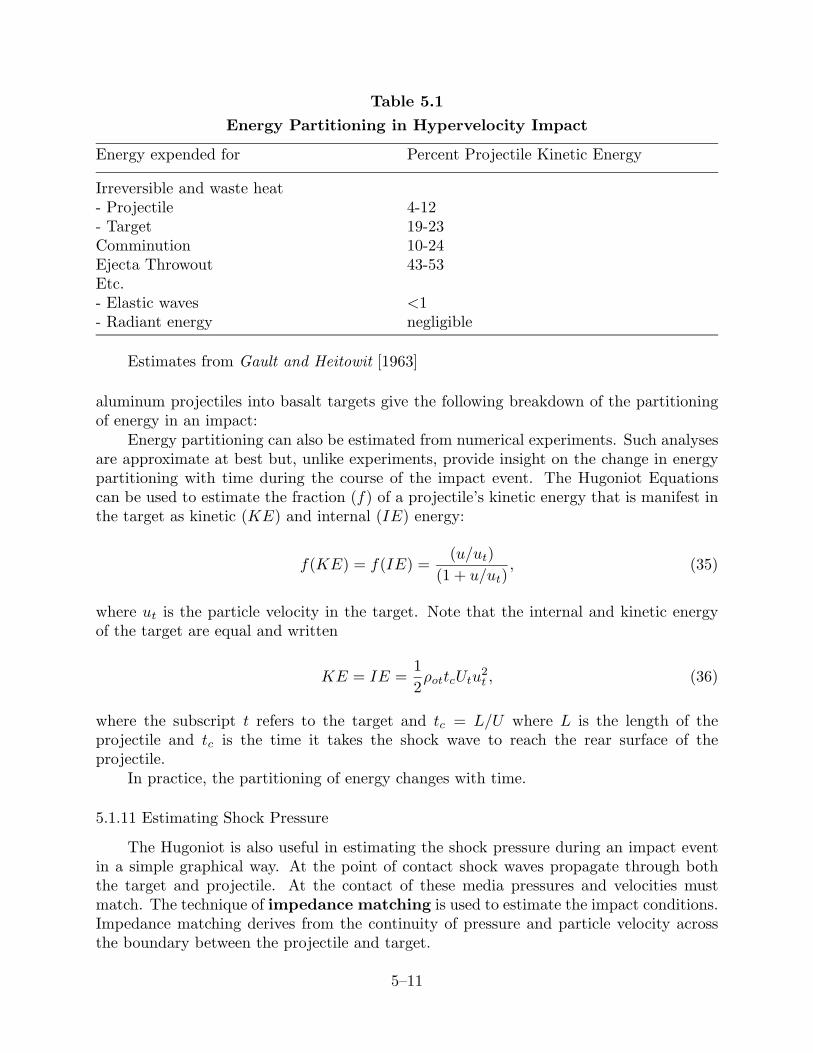
Table 5.1
Energy Partitioning in Hypervelocity Impact
Energy expended for Percent Projectile Kinetic Energy
Irreversible and waste heat- Projectile 4-12- Target 19-23Comminution 10-24Ejecta Throwout 43-53Etc.- Elastic waves <1- Radiant energy negligible
Estimates from Gault and Heitowit [1963]
aluminum projectiles into basalt targets give the following breakdown of the partitioningof energy in an impact:
Energy partitioning can also be estimated from numerical experiments. Such analysesare approximate at best but, unlike experiments, provide insight on the change in energypartitioning with time during the course of the impact event. The Hugoniot Equationscan be used to estimate the fraction (f) of a projectile’s kinetic energy that is manifest inthe target as kinetic (KE) and internal (IE) energy:
f(KE) = f(IE) =(u/ut)
(1 + u/ut), (35)
where ut is the particle velocity in the target. Note that the internal and kinetic energyof the target are equal and written
KE = IE =12ρottcUtu
2t , (36)
where the subscript t refers to the target and tc = L/U where L is the length of theprojectile and tc is the time it takes the shock wave to reach the rear surface of theprojectile.
In practice, the partitioning of energy changes with time.
5.1.11 Estimating Shock Pressure
The Hugoniot is also useful in estimating the shock pressure during an impact eventin a simple graphical way. At the point of contact shock waves propagate through boththe target and projectile. At the contact of these media pressures and velocities mustmatch. The technique of impedance matching is used to estimate the impact conditions.Impedance matching derives from the continuity of pressure and particle velocity acrossthe boundary between the projectile and target.
5–11
To perform impedance matching, the Hugoniot must be plotted in terms of pressureand particle velocity. Usually Hugoniots are given in terms of pressure-volume (P − V )or shock and particle velocity (U − u), but in either case the conversion can be simplyaccomplished using the Rankine-Hugoniot equations. The Hugoniot of the target is plottednormally. The Hugoniot of the projectile must be plotted ’backwards’, starting at theparticle velocity equal to the impact velocity. The intersection of the Hugoniots yields anestimate of the pressure behind the shock waves in both the target and projectile. From(3), the peak pressure associated with a projectile (subscript p) hitting a target (subscriptt) can be written
ρoP (ui − up)Up = ρotutUt (37)
where ui is the impact velocity. Note that in addition, the particle velocity of the targetand projectile can be read off from the x-axis corresponding to the intersection point.
In terrestrial impact craters, impact pressures and temperatures can be constrainedfrom field work. Low P/T minerals that are shocked will achieve higher P/T phases. Forexample, at increasingly higher pressures there will be a transition from quartz to coesiteto stishovite to amorphous silica glass. Plagioclase feldspar undergoes a transition tothe higher pressure phase maskelynite.
5.2 Stages of the Impact Process
The cratering process is a rapid process, but one which contains a distinct sequenceof events. As first proposed by D.E. Gault, impact events are divided into the contact andcompression, excavation, and modification stages.
5.2.1 Contact and Compression Stage
The first state of impact occurs when the projectile comes into contact with the targetsurface. The fast-moving projectile pushes target material out of its path, compressingit and accelerating it to a significant fraction of the impact velocity. Concurrently, thetarget’s resistance to penetration decelerates the projectile. Material in the contact zoneof the target and projectile are strongly compressed. Shock pressures developed duringhypervelocity impacts generally reach several hundreds of GPa and thus far exceed theHugoniot Elastic Limit of the target and impactor. The contact and compression stateends after the projectile has been unloaded from high pressure by the rarefaction wavegenerated when the shock wave impinges on the trailing end of theprojectile. This is theshortest stage of the cratering process, with a duration of contact
τ =L
vi(38)
where L is the projectile diameter and vi is the impact velocity. Contact and compressionlasts for less than a second for all but the largest impacts. In planetary-scale impact eventsmost of the projectile is vaporized.
The highest velocity material is ejected when the projectile first impinges on the target.The non-planar impingement of the projectile on the target generates localized zones ofhigh pressure near the edges of the projectile. Oblique contact angles are responsible for
5–12
increased peak pressures and particle velocities. From the highest pressure zones jets ofhighly shocked material are ”sprayed out”, at a velocity that may be a few times impactvelocity. This process is referred to as jetting. Jetting occurs very rapidly and usuallyfinishes within about half the time of the contact stage (Equation (38)). Jets include minoramounts of material in vertical impacts but may be more important in low angle impacts.
5.2.2 Excavation Stage
Excavation of the target initiates as the contact/compression stage ends. During thistime an approximately hemispheric shock wave propagates through the target material,weakening it severely. Because the shock wave is nearly hemispherical craters are usuallycircular and do not so deviate unless impact angles are less than 10◦ or so. The shockwave and rarefaction wave set target material in motion, initiating excavation that formsthe crater. Decompression by the rarefaction wave converts much of the internal energygained in compression into mechanical work. The energy converted is equal to the areabetween the release adiabat and the lines parallel to the axes on the P − V plot.
The peak pressure of the shock wave decays in an exponential fashion as
P (r) = Po
(ror
)b(39)
where 1.5 ≤ b ≤ 3, Po is the initial peak pressure, ro is the length of the isobaric core, andr is the penetration distance.
The crater that produced in the excavation event is many times larger than the pro-jectile, unlike low velocity impacts. The crater is formed by a combination of compressionand ejection of material from the crater. The ejecta blanket covers the surrounding ter-rain. The targets material strength and gravity become important. Excavation producesa bowl-shaped transient cavity that will later collapse under gravity. The shape of thecrater cavity is determined by the depth attained by material that is displaced downwardby compression beneath the crater. The excavation stage of a crater can take seconds tominutes to reach completion. Near the end of the excavation stage the target’s materialstrength and gravity become important in determining crater shape.
5.2.3 Modification Processes
During the ensuing modification stage, loose material slides down the steep interiorsof the walls of small craters and pools on the crater floor. Larger craters collapse moredramatically – slump terraces form on the walls and central peaks rise in the interior.At progressively larger diameters peak rings and rings will develop. At much longer timescales, diameters isostatic rebound may follow collapse, eventually flattening out craters.
On the long term, planetary surfaces, even those made of rock, behave to some extentlike a fluid. All substances will flow or creep on a characteristic time scale. The creeprate is strongly temperature dependent. The process of long-term flow of topography isreferred to as viscous relaxation, and is a consequence of the release of potential energyof topography due to the force of gravity; topography will seek to flatten out to minimizethe energy in the system.
5–13
Viscous relaxation of impact craters represents a means of probing the time-integratedthermal evolution of the shallow planetary subsurface. It is possible to quantify in a simpleway the process of relaxation. For a viscoelastic material the strain rate (ε̇) is a functionof the differential stress associated with topography (σ) as
ε̇ = AσneQ/RT , (40)
where A is the pre-exponential frequency factor, n is an experimentally-derived constantthat equals unity for linear or bf Newtonian flow is greater than one for nonlinear or non-Newtonian flow, Q is the activation energy, R is the gas constant, and T is temperature.In a viscolastic material the resistance to flow is commonly expressed by the Maxwelltime, tM , which can be expressed in terms of the strain rate as
tM =ε
ε̇=η
µ, (41)
where ε is the elastic strain, eta is the viscosity and µ is the shear modulus of the substrate.The viscosty is a resistance to shear and is a ratio of the shear stress over strain rate as
η =τ
2ε̇. (42)
Because even solid rock behaves as a fluid over geological time scales (hundreds of millionsto billions of years), crater topography will relax away over time, depending on the viscosityof the substrate. The rate at which a crater with depth d and diameter D will change canbe simply estimated to first order, as noted by Melosh [1989]. Stress is a force per unitarea so we take the negative buoyancy force associated with the crater cavity π/8ρgdD2
and divide by the area of the crater cavity π/2D2. This gives the shear stress (τ) beneaththe crater
τ ≈ 14ρgd, (43)
where ρ is substrate density and g is gravitational acceleration. From Equations (42) and(43), we find the strain rate of material that flows inward towards the crater to be
ε̇ =ρgd
8η. (44)
The rate of uplift of the floor is approximately the crater diameter times the strain rate,so
−dddt
= Dε̇ = d(t)ρgd
8η. (45)
Solving (44) as a function of time gives the temporal change of crater depth due to viscousrelaxation of crater topography
d(t) = d(0)e−ttR , (46)
where d(0) is the initial depth, and tr is the relaxation time of topography for a craterin a uniform viscous medium
tr ≈8ηρgD
. (47)
5–14
Equation (47) indicates that craters relax faster for higher gravity or density. In addition,craters relax faster for lower viscosities and large diameters. So large craters relax fasterthan small ones. Extending this, the long-wavelength characteristics of craters (e.g. di-ameters) relax fater than short-wavelength charactsterics (e.g. rims). This is true if thesubstrate viscosity is either uniform or decreases with depth (due to an increase of tem-perature with depth in the interior). To first order we know that is what the viscosity of ashallow planetary interior is like because some craters on the surfaces of the icy satellitesexhibit only short-wavelength structure such as rims; the broader crater cavities have re-laxed away. But sometimes even the rim of a crater on an icy satellite decays away andwhat is left is a quasi-circular albedo marking that is in essence the ”ghost” of a relaxedcrater. These ghost craters are referred to as palimpsests.
5.3 Crater Types
5.3.1 Simple Craters
Simple craters are the smallest hypervelocity impact structures. They are bowl-shaped in planform and have sharp rims, and over-turned stratigraphy in the ejecta blanket.The morphology of these structures is controlled mainly by the strength of the substrate.Simple craters have the largest depth/diameter ratio (d/D), where d ≈ 0.2− 0.33D.
5.3.2 Complex Craters
As impact energy increases, the target loses strength and there is a collapse of thewalls and an uplift of the crater interior. Complex craters are consequently formed ina regime where gravity is the dominant factor. Uplift is also associated wth unloadingasssociated with the rarefaction wave. Complex craters are characterized by terraced wallsthat are the surfical manifestation of subsurface faults, and they also show central peaksthat contain material brought up from deep beneath the crater. Complex craters havesmaller d/D ratios because the increased importance of gravity collapse results in moreuplift of floor. In these craters d ≈ 0.1D.
The transition from simple to complex craters depends on gravity according to
D ∝ g−1. (48)
The transition from simple to complex craters occurs at a higher diameter on planets withhigher gravity. For example, the transition occurs at a diameter of 3 km on the Earth andabout 18 km on the Moon.
5.3.3 Basins
The next morphological step up in the energy scale corresponds to basins, whichtransition from structures that have a central peak and rings (aka peak-ring basins) tono central peak and multiple rings (aka multi-ring basins). In the transition to a peakring basin the central peak collapses to form a small ring that increases with increasingimpact kinetic energy. In a multi-ring basin the number of rings scales with the impact
5–15
energy and the mechanical properties of the near-surface layer into which the impactoccurred.
Basins have even smaller d/D ratios than complex craters due to more central uplift.There have been arguments about whether basin penetration depth scales proportionallyor non-proportionally with respect to diameter in comparison to smaller craters. Themajority of researchers believe that the scaling is non-proportional with increasing basinsize, because if it was proportional then we should be sampling well into the mantle of thelargest impacts on some planets and there is no geochemical evidence to suggest that thisis the case. As for simple-complex craters, the diameter of the complex crater to basintransition also depends on gravity, but the morphology of large multi-ring basins cannotbe attributed to gravity alone.
5.3.4 Crater Size
How big will a crater be for a given impact? The answer depends on the materialproperties of the target, the velocity and angle of impact, whether the impact occurs in thestrength or gravity regime, and other things. A simplified scaling relationship for craterradius R can b e written
R
(ρtmp
)1/3
= f
(Y
ρpU2p
,grpU2p
), (49)
where ρt and Y are the density and yield stress of the target, mp, Up, ρp and rp are themass, velocity, density and radius of the impactor, and g is gravitational acceleration.
5.4 Crater Statistics and Relative Ages of Planetary Surfaces
5.4.1 Impactor Populations
Craters can be used as relative age markers by counting their numbers and size distri-butions on a planetary surface. To use craters in the dating of surfaces one must considerthe rate of crater production and obliteration. Estimates of crater production requirean estimate of the flux of impacting bodies and the effect of an atmosphere, if relevant,in ablating incoming projectiles. Obliteration represents the processes that remove cratersfrom surfaces and may include erosion, lava flows, overlapping impacts or ejecta from near-by impacts, subduction, and viscous relaxation. To assess the crater population, theprincipal piece of information is the measured number of craters as a function of diameterover planetary surfaces over all ages.
5.4.2 Crater Counting
By counting the number of craters on a planetary surface it is possible to derive anestimate of relative age. That is, one can tell how old one surface is compared to anotheron the same planet. The determination of an absolute age would require knowledge of theflux of impactors (asteroids, meteoroids and comets), which are generally poorly known.
5–16
The principal piece of information in crater counting is the number of craters perunit area as a function of diameter. Cumulative frequency distributions are usuallyemployed, where Ncum is the number of craters per unit area equal to or greater than agiven diameter. The number of craters of a given diameter that would be expected is aproduct of the flux rate and surface area. It has been shown in practice that the cumulativecrater distributions closely approximates a power law function of diameter:
Ncum = αD−β (50)
where β=1.8 for post-maria craters on the Moon. Equation (50) indicates that the bestconstraints on relative age come from small craters, which are more abundant that largecraters.
The fact that β ≈2 is interesting because when β=2, α is dimensionless because Ncumis the number of craters per unit area. This relationship corresponds to a situation wherecraters follow a fractal distribution and are therefore scale-invariant. A population ofcraters with a power law near two might arise from a formation process in which there isno length scale, or perhaps a series of independent processes that are so complex that nosingle length scale dominates.
The integral of the crater production rate over the age of the surface is a specialtheoretical crater population known as the production population. A production pop-ulation is the size-frequency distribution of all the craters (excluding secondary impacts– those that occur as ’offshoots’ of an impact) that have ever formed since craters beganaccumulating on the surface. The population is theoretical in the sense that it ignores allobliteration processes, and is hence never observed, though crater populations on lightlycratered surfaces may approximate a production population. The production populationis a useful concept for the study of the evolution of crater polulations. Such studies usuallybegin with an assumed or inferred production population and then postulate a model ofcrater obliteration that results in a predicted crater population that matches the observa-tions.
If cratering continues the case will arise that the number of craters cannot increasedespite the fact that impacts are still occurring. This is because there are so many craterson the surface that is in a state of saturation, and every new impact will remove existingcraters. A surface that has been saturated with craters is referred to as an equilibriumsurface. On equilibrium surfaces only a lower limit of the relative age can be obtained.
On Earth there are very few impact craters because there are so many processes thatremove craters such as erosion and subduction. The best studied planet from the pointof view of crater populations is the Moon. Crater counting has shown that the rate ofcratering has declined significantly over the past 4.5 BY. The Moon is the one planetarybody where absolute ages of surfaces have been derived in part from crater counts. Thisis because we have absolute ages of some areas from lunar samples, and this permits therelative age curve to be ’anchored’. Lunar crater counts indicate an exponential drop inthe flux at about 4 BY. Highland terrains have ages greater than 4 BY and the mariamostly have ages that span 3.8-4.0 BY. There are very few surfaces younger than 3 BY,and these are associated with localized volcanic events.
5.5 Case Studies
5–17
5.5.1 Meteor Crater
Meteor Crater, first recognized as an impact structure by Eugene Shoemaker, formed50,000 years ago by the passage of a 40-50 m iron projectile through Earth’s atmospherewith an impact velocity of 11 km s−1. The crater is 1.2 km (0.8 mi.) across and 200 m deep.The kinetic energy released is estimated to have been 15-20 megatons (1000 Hiroshimas orNagasakis, which were about 15 kilotons). Because of its excellent preservation state andeasy accessibility which enabled many years of detailed analysis, data from Meteor Craterhas provided the basis for much of our current understanding of planetary impacts.
5.5.2 Tunguska
The Tunguska impact event occurred in 1908 in a remote region of Siberia. Theimpact produced an area of devastation 1000 km2. While there was much evidence ofmassive destruction, no crater was produced. After many years of study, made difficutbecause of inaccessibility to the site, it was determined that the event was probaly a stonymeteor 80 m across that disintegrated in the atmosphere shortly before impact. The impactvelocity was estimated to be about 22 km s−1.
5.5.3 Cretaceous-Tertiary Event
In 1980 there was a paper published that changed the way that many people thoughtabout the evolution of the Earth. Before this paper it was a strongly held belief amonggeologists that the Earth evolved through a series of gradual changes. This included theformation of landforms and the evolution of life. For example, mass extinctions wereattributed to causes like gradual changes in climate. The paper by Walter Alvarez andcolleagues in Science magazine challenged this way of thinking.
Geologist Walter Alvarez of Berkeley had been analyzing clays in a thin layer at theCretaceous-Tertiary (K-T) boundary in an outcrop in Gubbio, Italy. Chemical analysis ofsediments in the immediate vicinity of the boundary layer showed them to be enriched inthe element iridium by a factor of ≈ 10 over what would be expected. The only rocks thatcontain iridium in that concentration are iron meteorites. Alvarez and colleagues (whichincluded his father Luis, the Nobel Prize-winning physicist) boldly hypothesized that theK-T extinction, which wiped out nearly half the species on Earth, was a consequence of theimpact of an asteroid ≈ 10 km in diameter. Others argued that elements like iridium werealso enriched in volcanic rocks (though none were present in the concentration observedat the K-T boundary) and they alternatively hypothesized massive volcanism at the timeof the boundary. (Interestingly, the massive Deccan traps in India have the same age asthe K-T.)
Alvarez’s paper inspired many workers to closely analyze K-T boundary sediments allover the Earth, including sediment cores from the ocean. The results were astounding.Iridum and other similar minerals were everywhere enriched in these layers. Results indi-cated that the K-T in many areas also displayed a distinctive ash layer. indicated that therewere wildfires large enough in scale to preserve a global signature. Ash was apparentlycarried up in the atmosphere and distributed over the Earth. It was hypothesized that somuch ash was thrown into the atmosphere that it blocked sunlight for several months to
5–18
a year. The estimate is that the atmosphere at that time contained ≈ 100 times as muchdust lofted by any volcano in the past 2 centuries.) Calculations based on ash abundanceand distribution suggested that the dusty atmosphere implied from the cores could havedepressed global temperatures from a few degrees to up to 10◦, which would sever thefood chain in many places. If this occurred, it was argued, many life forms, including thedinosaurs, could have have succumbed.
Further evidence came to light in the form of shocked quartz grains, that were onlyknown to be produced at impact pressures. The propagation of a shock wave throughcertain minerals produces changes in crystal structure that are observerable in microscopicthin sections and are diagnostic not only of the fact that shock has occurred but also ofthe magnitude. This evidence pointed strongly toward an impact, though the actual craterhad yet to be found. The problem was that impacts are not well preserved on Earth. Oddswere that the impact, if that was indeed the explanation for the iridium, carbon, and shockfeatures, occurred in the ocean, where the signature would be difficult to detect. Therewas even a finite probability that the crater had subducted back into the mantle. On thecontinents erosion, sedimentation and vegetation makes identification of impact structuresa challenge. There are only about 140 craters on Earth, and no known crater close to 65MY in age that was big enough to have produced the kind of ”event” implied by the K-Tevidence. Then in 1992 the smoking gun was found. Scientists doing field work in Haiti inthe Caribbean looking at K-T sediments and found abundant glass spherules representingmelted sediments. This indicated that this area was close to ’ground zero’. So the searchwas on. After some effort scientists obtained marine gravity maps and well cores in theGulf of Mexico. These data had existed some time but were mostly proprietary becausethe measurements were made by oil companies that were prospecting. Alan Hildebrand,then a graduate student at the University of Arizona, found evidence in seafloor gravityof a buried circular structure just off the Yucatan Peninsula of Mexico. Core samplesverified that indeed the structure was produced in an impact event. The crater is calledChicxulub, and with a diameter of 180 km it is the largest known terrestrial impactcrater. Energy scaling calculations suggest that the crater was produced by an ≈10-kmdiameter projectile. Its age was determined to be 64.98 MY, which placed it precisely atthe K-T boundary.
There is now no doubt of a catastrophic impact at the end of the Cretaceous. Butwhether or not the impact was directly responsible for the mass extinction is still hotlydebated. In any case, the Chixulub event provided the impetus to better understand thepotential links between impacts and biological processes.
5.5.5 South Pole-Aitken Basin
South Pole-Aitken is a 2200-km diameter impact basin on the far side of the Moon.It could have been produced by a 215-km diameter projectile with an impact velocity of20 km s−1 or a 900 km diameter projectile at 2.4 km s−1 (lunar escape velocity). Despitean age of more than 4.1 BY, the basin retains over 8 km of topographic relief. Spectralanalysis of the basin floor reveals materials with mafic composition that indicate thatthe impact penetrated into the deep upper crust (but not well into the mantle as wouldbe required by proportional scaling of d/D ratios). The azimuthal heterogeneity of the
5–19
structure suggests a slow, oblique impact.
5–20
Problems
5-1. The Galilean satellite Callisto is in synchronous rotation about Jupiter and thereforekeeps the same hemispheres at the apex (leading hemisphere) and antapex (trailing hemi-sphere) of orbital motion. The weighted mean impact velocities at the apex and antapexof Callisto are estimated to be vi−apex=23 km s−1 and vi−antapex=13 km s−1. Assumethe impact of a pure H2O ice comet into a pure H2O ice surface. Use the impedancematching technique and the attached Hugoniot curve in Figure ?? to estimate the ratioof the average peak pressures for impacts into the leading and trailing hemisphere. Alsoestimate the particle velocities of the projectile and target at the time of initial impact.
5-2. Figure ?? plots amount of melt and vapor produced by basaltic impactors of varioussizes and impact velocities into a granitic target (i.e. terrestrial continental crust). The plotindicates that for given impactor and target types and fixed impact kinetic energy, slowlarge bodies produce more melt than fast small bodies. However, the Rankine-Hugoniotequations indicate that the greater the impact velocity the greater the peak pressure andtherefore the greater amount of waste heat trapped in the area between the Rayleigh lineand the release adiabat (or Hugoniot). Why, then, does a small fast body produce lessmelt than an energetically equivalent large slow body?
5-3. Altimetry and radar imaging data from the Magellan spacecraft indicates that thetopography of impact craters on Venus is virtually unrelaxed. (a) Assume that the Venuslithosphere can be approximated by a halfspace of uniform viscosity. Also assumed thatmost 10-km diameter craters have shallowed by approximately 10same size. Given a surfacedensity of 300 kg m−3 and the gravitational acceleration of the Venus surface of 8.87 ms−2, estiamate the viscosity of lithosphere and the relaxation times of for craters with agesof 0.01, .1, 1 and 4 GA. Calculate the viscosity in units of Pa-s (kg m−1 s−1) and relaxationtimes in years. (b) A slightly more realistic structure for the Venusian lithosphere may bea halfspace in which viscosity decreases exponentially with depth. Assume that the depthof 10-km diameter craters is much less than the scale depth of the lithosphere. Wouldthe relaxation times determined in (a) increase, decrease or stay approximately the same?What about for a 100-km diameter crater whose depth is comparable to the scale depthof the lithosphere?
References
Gault, D.E., & E.D. Heitowit, 1963, The Partition of Energy for Hypervelocity ImpactCraters Formed in Rock, Proc. Sixth Hypervelocity Impact Symposium, 419-456.
Hartmann, W.K., R.G. Strom, R.A.F. Grieve, S.J. Weidenschilling, J. Diaz, K.R. Bla-sius, C.R. Chapman, A. Woronow, E.M. Shoemaker, M.R. Dence, & K.L. Jones,1981, Chronology of planetary volcanism by comparative studies of planetary crater-ing,Basaltic volcanism on the terrestrial planets, Pergamon Press, New York.
Melosh, H.J., 1989, Impact Cratering: A geological process, Oxford University Press, NewYork.