Endress+Hauser magazine www.ca.endress.com Issue 76 |07/16 talkline 22 E-direct products spotlight Check out the benefits of these eight featured products you can now order directly online 5 pH in practical terms Understand the theory of pH, how it is measured, the individual components, and more 4 Online product purchase E-direct
talkline22 E-direct products spotlight Check out the benefi ts of these eight featured products you can now order directly online
5 pH in practical terms Understand the theory of pH, how it is measured, the individual components, and more
4 Online product purchase
E-direct
2 talkline 76
Index
4 About E-directE-direct is a fast, eff ective direct purchase channel to 100% Endress+Hauser quality products at the best price.
5 Understanding pH in practical terms Understand the theory of pH, how it is measured, the individual components, plus learn how to care for pH sensors and more.
21 Process Automation Training• Certifi ed PROFIBUS training
for process automation • FOUNDATION Fieldbus training
for process automation
22 E-direct Products SpotlightCheck out the benefi ts of these eight featured products, then order directly online
/EndressHauserCanadaLtd
/Endress_CA
/company/endress-hauser-canada-ltd-
Connect with usFor the latest updates, events and process automation news, join us on our social media channels. Visit Endress+Hauser Canada Ltd on Facebook, Twitter and LinkedIn.
July 20–21 RAOTM Calgary, ABSeptember 18–21 ACWWA (Atlantic Canada), Moncton, NBSeptember 24–28 WEFTEC, New Orleans, USAOctober 4 Eastern Ontario Process & Automation Show, Nepean, ONOctober 18 CsHm Grande Prairie, ABOctober 22–23 NWOWWC, Thunder Bay, ON October 25–26 Eastern Ontario WWA, Ambassador Hotel, Kingston, ONOctober TBD Symposium sur la gestion de l’eau 2016, QCNovember 8 North Saskatchewan Process & Automation Show, Saskatoon, SK
Trade Shows 2016
3talkline 76
Welcome to the second issue of Talkline for 2016! In this issue we introduce E-direct. What is E-direct? It’s our online portal, where you can order the high-quality products we are known for, at highly competitive prices … and with fast delivery! Just another one of the ways we continuously work to help you to be as competitive and efficient as possible. More on E-direct can be found in the pages ahead. Do yourself a favour and check out E-direct. Kick the tires. Give it a test drive. I am confident you will find the E-direct portal of great value for ordering simple, high-quality products, with attractive pricing — and receiving them in very short delivery times. You can access the E-direct online portal via this link starting July 1: www.e-direct.endress.com
Also found in the pages ahead, we share a white paper on “Understanding pH in Practical Terms.” Dig into the theory of pH and how it is measured. Look in detail at the individual components and discover the proper methods for calibrating, cleaning and general care of the pH sensor. pH plays an integral part of almost everything we eat, drink and for the most part, touch. So in essence, we measure pH because we have to! Learn more in the pages that follow.
We have many exciting projects underway to improve our efficiency and effectiveness in serving our customers. We have started to optimize our internal cost structure by evaluating our supplier contracts (as our customers are doing with us !) and renegotiating contracts for everything from mobile communications to leases to lower our operating costs and freeing up capital to invest in the market.
We introduced a new component to our sales organization called Contact Sales. This team of three people (one in each region) is now responsible for providing a similar customer experience as our outside sales team does however they remain in the building and can speak with between 20 and 25 customers per day. This highly successful model is being rolled out by Endress+Hauser in various subsidiaries globally and Canada is the sixth Endress+Hauser company to adopt the model. We have already seen (and heard from our customers) the success of the program in reconnecting us with small or dormant customers.
At Endress+Hauser, we are committed to deliver meaningful and tangible ways to help you be the leader in your industries. Together, in a spirit of partnership, there’s nothing we can’t accomplish successfully together. Look to us to help you to be as efficient and competitive as possible.
Sincerely,
Anthony VargaPresident and CEO
Our valued friends, customers and business partners
4 talkline 76
What is E-direct?E-direct complements the traditional range of products from Endress+Hauser. Certain instruments do not require a vast amount of consultation in terms of application and price – that’s where E-direct can help. It’s a product portfolio that offers simple product selection and fast delivery at an affordable price.
Who is Endress+Hauser?Endress+Hauser is a global leader in high quality and innovative measurement instrumentation, services and solutions for industrial processes. With dedicated sales centers and a strong network of partners, Endress+Hauser guarantees competent worldwide support.
What does E-direct off er me?• Simple product selection• Value for money• Transparency thanks to quantity
discounts being displayed• Short delivery times• Exchange of defective instruments
How can I place an order?You can place your order with us online or by contacting our sales office at 1-800-668-3199
How can I pay?You can pay online using a credit card (MasterCard - Visa) or by purchase order number with pre-approved credit. Orders paid by Credit Card will be process immediately. Orders purchased on pre-approved credit will be invoiced with terms.
Invoicing for current customersIf you have an established account with Endress+Hauser and your account is in good standing, your order will be immediately processed and an order confirmation will be sent to you. An invoice will then be sent once the order is shipped. Endress+Hauser Canada Ltd Terms and Conditions of Sale apply.
Invoicing for new customersYou will be contacted by an Endress+Hauser representative to set up your account after you submit your order. This will include completing a credit application. Upon approved credit, an order confirmation will be sent to you once your account is established. An invoice will then be sent when the order is shipped. Please review Endress+Hauser Canada Ltd. Terms and Conditions of Sale for further details.
ConsultationOur technical experts are available during office hours to answer any questions you may have regarding our E-direct products and their application at 1-800-668-3199.
WarrantyOur standard warranty terms and conditions apply. Please refer to the Endress+Hauser Canada Ltd Terms and Conditions of Sale.
Dispatch timesPlacing your first order using a credit card will ensure prompt dispatch. If you opt to place your first order by purchase order number, the dispatch of your ordered items may be delayed whilst we organize your account and Proforma invoice.
PLEASE NOTE:• The dispatch time displayed
alongside each product is an indicator e.g. 48 hours or 5 working days (for three identical units) and will be confirmed in your order confirma tion. This dispatch time applies for orders placed before 09.00 a.m.
• Our dispatch times may sometimes be longer than 48 hours or 5 working days. Should this happen you will be advised by the dispatch time indicator.
= 48 hours (Your order will be dispatched on the second working day after order placement)
= the indicated number of working days
Shipment by Air Express is available at an additional cost.Shop now!
www.e-direct.endress.com
About E-direct
48h
5wd
5talkline 76
Why measure pH?In everyday life, pH plays an integral part of almost everything we eat, drink and for the most part, touch. The determination of pH in factories, water and wastewater plants and in research laboratories is one of the most common measurements made, and yet, it remains as somewhat of a magical or mystical measurement, if not a frustrating one. Talk to most plant operators or I&E technicians, and their most common complaint is one of keeping the pH sensors up and running.
The following text explains pH theory, practical determination, and proper care and feeding of the friendly beast we call pH.
In general, pH is used to determine whether:
• Municipal drinking water plants are producing quality drinking water
• Municipal wastewater plants are discharging clean water to their receiving bodies (lakes, rivers, streams etc.) and/or the water is not too corrosive and does not do damage to cement/cement lined pipes
• Factories, which vary from steel and automobile production to food and beverage, are producing product that meets both consistency and quality specifications
• The manufacture of electrical power is optimized for the processes for inlet water treatment, steam cycle, cooling tower water and any wastewater discharge
Understanding pH in practical termsBy Frederick Kohlmann, Analysis Product Business Manager, Endress+Hauser, Inc.
Understand the theory of pH and how it is measured, the individual components, the importance of specific items related to the measurement and the proper methods for calibrating, cleaning and general care of the pH sensor.
6 talkline 76
To sum it up, almost every process that contains water and undergoes a chemical reaction probably depends on pH and the more closely the reaction is held to the optimum pH, and the more accurate the pH measurement, the better the outcome of the process or product. Bottom line: We measure pH because we have to.
Defi nition of pH?Version one: The pH unit is a number set ranged from 0 to 14, where 7 indicates a neutral pH value. Increasing values from 7 to 14 pH indicate increasing alkalinity concentrations, and decreasing values from 7 to 0 pH indicate increasing acidic concentrations. Simply put, this pH numbering system is used as a unit of measurement relating to the acidity or alkalinity of a liquid. A specially formulated glass electrode supplies an ECP (electrochemical potential) in conjunction with a reference element and a voltage measurement device (pH analyzer/transmitter) to determine the pH value of a liquid.
Further, the ECP generated by the glass measuring electrode is dependent on H+ ions penetrating through the outer layer of the glass, through the hydrated glass layers, then through the internal gel layer of the glass, the electrolyte solution and then to the silver/silver chloride (Ag/AgCl) internal reference element.
Ultimately, this ionic pathway causes a voltage potential difference between the outer glass gel layer and the gel layer existing on the inside of the glass electrode. A voltage is produced from this reaction and subtracted from the voltage provided by the reference electrode to yield an overall voltage potential relative to pH. A transmitter measures this electrical potential and converts the measured voltage into a corresponding pH value based on the Nernst equation.
Version two: pH is defined as the negative log of the hydrogen ion concentration in mol/L: pH = -log H+
The pH unit of measure exactly quantifies the degree of acidity or alkalinity an aqueous solution possesses. pH
measurement is logarithmic, the voltage output of the sensor is linear in its output.
So why two versions? Well, each is correct — technically speaking — and each describes pH from a different yet accurate position. Version one describes how pH works and Version two describes what pH is.
Let us put this into practical terms. What if someone approached you and said “It is really cold outside”. Depending on where you are from, or what climatic conditions you are used to, cold has varying meanings. If you lived in Alaska all your life and just happened to be vacationing in Florida in mid-July and the thermometer showed 60°F, the locals might say that is cold. But to you, your Arctic blood still senses this as warm. So without actually feeling the temperature outside or knowing what the temperature was in specific degrees, you would never really know what the term cold meant.
pH holds the same analogy. Just saying something is acidic or alkaline, doesn’t give a good enough definition of what’s really going on. Some type of number system has to be in place to define the degree of acidity or alkalinity. Hence, the pH scale was developed to do just that. It relates a number to the ratio of hydrogen ion and hydroxide ion concentrations. This relationship is inversely related. That is to say that as the (H+) increases the (OH-) decreases.
The pH scale has a range of 0 to 14, where 7 pH is considered neutral. Anything from pH 7 to pH 0 is considered acidic and from 7 to 14 pH alkaline. The more acidic the solution, the more (H+) are present, and the less OH- present. This relationship is always constant, and so knowing one, we can determine the other.
H2O = H+ + OH-
In theoretically pure water (7 pH), at 77°F/25°C, the amounts of hydrogen and hydroxide ions are equal, and their product is always 10-14.
Dissociation constantAs long as we introduced the terms hydrogen ion (H+) and hydroxyl ion concentrations, let’s explain what these mean.
All solutions have compounds within them that form ions. Ions are charged particles that have either gained or lost
The logarithmic nature of pH Changing pH from 6 to 7 pH is a diff erence of only one pH unit
but a 10-fold change in concentration of ions. Changing from 5 to 7 pH is a diff erence of two pH units in value, but a 100-fold change in ion concentration.
Figure 1: pH values of common liquids
Note The pH electrode is temperature dependent. As the temperature of the solution
and ultimately, the pH measuring electrode changes, so does the output of the glass electrode.
7talkline 76
electrons. The rate at which these ions gain or lose electrons is determined by the compounds in solution. These ions allow electrical energy to be passed through the solution and so the ions act as a conductor.
In mathematical terms, the dissociation constant for water (KW) tells us that in aqueous solutions the product of (H+) and (OH-) (at 77°F/25°C) always equals 10-14.
KW = (H+) (OH-)
The Nernst equation and temperature compensationAs stated earlier, the pH sensor output is temperature dependent. As temperature changes, so does the pH sensor’s millivolt output. Specifically, the electrode produces more millivolts/pH as the temperature increases, and as the pH goes further in either direction from 7 pH. This change is predictable and linear, and can be compensated for in the pH analyzer by using the Nernst equation in the circuit design. The Nernst equation is a general mathematical equation that describes and predicts the pH electrode’s output based on a number of factors, all of which are constant, with then just one variable, temperature.
The Nernst equation is stated as:U = UO - 2.3RT • H+
nf
where:U = sensor voltageUO = voltage at 7 pHR = gas constantT = absolute temperature (Kelvin)n = load of the ion (H+ = 1)f = Faraday constantH+ = activity of the ion
Hydrogen ion concentration in moles/litre at 77°F (25°C)
Based on the Nernst formula, changes in temperature, when all other variables are known, will alter the output of the glass pH electrode. At 77°F (25°C), this output is calculated as 59.16 mV per pH unit. At 77°F (25°C) and pH 7, the electrode produces 0.0 mV output, the isopotential point, and no change with temperature. For every decade of pH change thereafter, the output changes by ± 59.16 mV. Since pH has a negative slope, as the pH increases, the mV potential decreases.
If the temperature effects of the glass electrode were left uncompensated for within the circuitry of the pH analyzer, temperature would cause large errors in the measurement as shown: @ 77°F (25°C) = 59 mV per pH change@ 32°F (0°C) = 52 mV per pH change@ 212°F (100°C) = 74 mV per pH change
Vertical shift of ISOPOTENTIAL ERROR in temperature compensation corrected by standardization
Figure 2: Theoretical mV output of a pH sensor @ 77°F (25°C)
8 talkline 76
In a 4 pH solution at 32°F (0°C), the indicated pH would be -21 mV in error and that equates to approximately 0.3 pH units for a reading of 4.3 pH. In a solution of 11 pH and 212°F (100°C), the indicated pH would be -45 mV in error and that equates to approximately 0.6 pH units for a reading of 10.6 pH.
Solution temperature compensationIt should be noted here that the Nernst compensation factor is for the effects of the pH glass responding differently to temperature changes as temperature effects the glass’s ability of ionic transfer. This is not the same principal as solution temperature compensation. Solution temperature compensation is based on the fact that as solutions are changing with temperature, their pH also changes (changes of the hydrogen ion (H+) activity). This change, usually in % / (°C) is solely based on the characteristics of the chemistry of the solution and not that of the glass’ response to temperature change.
pH sensor theoryWe can think of a pH sensor in similar fashion to that of a battery. A battery (also known as a galvanic cell) converts chemical energy to electrical energy via two half cells connected across a conductive electrolyte. The battery has a positive electrode (anode), and a negative electrode (cathode). These electrodes do not touch each other but are electrically connected via the electrolyte.
Each half cell produces an electromotive force (emf). The sum of these forces is the total voltage output of the
battery. As an example, a fresh AA battery produces about 1.55 volts DC.
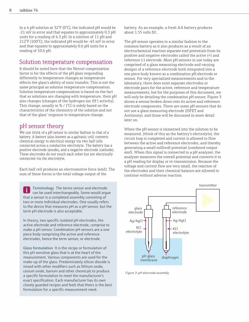
The pH sensor operates in a similar fashion to the common battery as it also produces as a result of an electrochemical reaction separate emf potentials from its positive and negative electrodes called the active (+) and reference (-) electrode. Most pH sensors in use today are comprised of a glass measuring electrode and varying designs of a reference electrode both integrated into a one piece body known as a combination pH electrode or sensor. For very specialized measurements and in the laboratory, there does exist separate electrodes or electrode pairs for the active, reference and temperature measurements, but for the purposes of this document, we will only be detailing the combination pH sensor. Figure 3 shows a sensor broken down into its active and reference electrode components. There are some pH sensors that do not use a glass measuring electrode (ISFET and Antimony), and those will be discussed in more detail later on.
When the pH sensor is immersed into the solution to be measured, (think of this as the battery’s electrolyte), the circuit loop is completed and current is allowed to flow between the active and reference electrodes, and thereby generating a small millivolt potential (combined output emf). When this signal is connected to a pH analyzer, the analyzer measures the overall potential and converts it to a pH reading for display or re-transmission. Because the voltage and current flow are very small, the reaction of the electrodes and their chemical balance are allowed to continue without adverse reaction.
transmitter
reference electrode
Ag/AgCI
KCI electrolyte
pH glass membrane
diaphragm
KCI electrolyte
Ag/AgCI
glass electrode
Terminology The terms sensor and electrode can be used interchangeably. Some would argue that a sensor is a completed assembly consisting of two or more individual electrodes. One usually refers to the device that measures pH as a pH sensor, but the term pH electrode is also acceptable.
In theory, two specifi c isolated pH electrodes, the active electrode and reference electrode, comprise to make a pH sensor. Combination pH sensors are a one piece body comprising the active and reference electrodes, hence the term sensor, or electrode.
Glass formulation It is the recipe or formulation of this pH sensitive glass that is at the heart of the measurement. Various components are used for the make-up of the glass. Predominately silicon dioxide is mixed with other modifi ers such as lithium oxide, cesium oxide, barium and other chemicals to produce a specifi c formulation to meet the manufacturer’s exact specifi cation. Each manufacturer has its own closely guarded recipes and feels that theirs is the best formulation for a specifi c measurement need.
Figure 3: pH electrode assembly
9talkline 76
Active electrodeA pH sensor’s active electrode, also known as the measuring electrode is the work horse of the total assembly called the pH sensor. It is this portion of the sensor that does the real measuring. Without it, the measurement could not take place, and even with it, the measurement is almost too fragile to be made.
The active electrode is usually constructed with the tip of the electrode being a pH sensitive glass (a bulb, dome or flattened surface) blown onto a stem of more or less, standard type laboratory glass.
Glass impedanceAt 77°F (25°C), a glass electrode has very high impedance, and varies by manufacturer, anywhere from 20 to 1000 megohms. Ranges between 200 and 800 megohms of impedance are typical. As mentioned, glass impedance changes with temperature. As a general rule of thumb, for every 14.4°F (8°C) change in temperature, the glass impedance doubles as the temperature decreases, and glass impedance halves as the temperature increases.
In terms of pH error on uncompensated temperature changes, the error is fairly consistent at 0.003 pH / (°C) / pH. This is to say that if the pH sensor were calibrated at 77°F (25°C) and the sample to be measured were at a pH of 4, and 73.4°F (23°C) and not compensated, the error would be 0.018 pH (0.003 x (2°C) x 3 pH units). At or near 7 pH, the error is fairly insignificant. Let’s examine the error with the following conditions:
• Calibrate the sensor in 7 buffer at 77°F (25°C) • Measure the process pH with active temperature
compensation (=3 pH)• Actual process temperature = 131°F (55°C)• In an uncompensated reading, we would see a fairly
significant error of 0.36 pH and a reading of 2.64 pH on the display (0.003 x (30°C) x 4 pH units) = .36 pH error
Active electrode gel layerWhen immersed into the solution to be measured, the active electrode starts its work. Because the pH electrode is specifically designed to measure hydrogen ion activity, immediately after immersion, a galvanic potential is formed, based on the Nernst equation, due to charge exchanges between a now formed hydrated outer gel layer surface on the glass electrode and its inner gel layer surface.
As the inner fill solution is at a pH of 7, any difference in the outer solution’s pH will generate an unequal potential of hydrogen ions. The hydrogen ions (charges) move through the glass layers until they come to equilibrium). It is this potential that produces the emf output of this electrode through the glass, KCl solution and then through the silver/silver chloride wire to one input of the pH analyzer. The reaction ceases once the charge transfer (difference in hydrogen ion activity) is enough to cancel out the tendency for the reaction to occur. It is at this point that the emf output is constant.
Active electrode issues and concernsThink about what you are asking your active electrode to do. Yes, it is to measure pH. But the pH of what? Drinking water? – no real problem but what about plant effluent from a hazardous chemical waste disposal company? These are two extremes, but two very real measurement needs. The drinking water application is fairly benign. It is usually around 7 pH, so the electrode is not working very hard since its isopotential is also at 7 pH. The temperature is usually ambient, more towards the colder side 50°F (10°C) to maybe 75°F (23.9°C), and pressures are usually well within the sensor’s range, so no real issues.
As for the chemical waste disposal application, the pH could be anything from very acidic, 0-2 pH to something very alkaline, 11 pH or higher. Temperatures could be very hot, perhaps 200°F (93°C) or more, and if the sensor
is in a pipeline, the pressures could be at 100 psi or greater. Imagine what is happening to the glass when exposed to these extremes. In order for the glass to do its job, it must be clean and allow the migration of hydrogen ions across its geometry. If the glass becomes coated, or the gel layer becomes disturbed or is eliminated, this migration is impeded and the signal is not accurate. If the temperature is too cold or too hot, or fluctuates widely, the ability of the glass to do its job also changes, and if the temperature gets too hot, the internal fill solution undergoes changes and may even come to a boil. Many times sensors are taken out from extremely hot processes for calibration only to be submerged into cold rinse waters or buffers. This sudden temperature change has been known to fracture or crack the glass. Sometimes the cracks or fractures are so small they are hard to see, other times, the glass may shatter completely. Within many processes, solids may be present in such magnitude as to not only coat the glass, but break the glass from shearing forces or have solids that are big enough (chunks) that when the sensor is installed in a pipeline, these chunks flow through the piping and impact the glass like a bullet.
It is for these reasons that specialty glass is constructed and frequent calibrations of the pH sensor are necessary. Imagine you are in your kitchen preparing the evening meal. You can see everything around you in vivid color and clarity. Now you pick up an especially juicy, ripe lemon and slice it in half to pour over your flounder. But, just as you cut into it, you get sprayed in the eyes. What happens to your vision? Because of the acid in the lemon, for a few seconds, you can’t see, your eyes burn and they immediately start to tear up. This is analogous to a pH sensor in the process — think of the pH sensor as your eye ball. Depending on the process, it may take a while for the sensor to come to equilibrium and adapt to its surroundings.
If the measuring glass is exposed to grease, oils or fats, the glass will become coated and can’t see the process to be measured. The glass needs to be cleaned to once again be able to see properly. But what if your process is
continually coating the glass? Well, you need to continually clean the glass. It’s just the way it is. That’s why pH has been described as one of the most maintenance intensive and difficult measurements one can make.
Sodium ion error, Na+ (alkaline error)Sodium ion error (Na+) is common and is only present as the pH rises over approximately 11 pH. Values of less than 11 pH have very little sodium ion present. Sodium ion error exists because the pH glass becomes confused. The confusion occurs as the glass electrode responds to and takes into account (or measures) the addition/concentration of sodium ions and hydrogen ions within the process. These sodium ions are similar in size to hydrogen ions and can be interpreted by the glass electrode as an excess of hydrogen ions, thereby artificially lowering the pH. (The higher the H+ concentration, the lower the pH.) Sodium ions penetrate the molecular structure of the glass electrode’s silicon-oxygen amalgam, and form an asymmetry potential difference (the difference in potential) between the inner and outer layers of the glass, causing an offset error.
As sodium ion error only occurs at the high end of the pH scale, above 11 pH, most general purpose electrodes function well at this level. Above 11 pH, one should consult the sensor manufacturer for a specific type of pH sensor that uses low sodium ion error glass. This glass is specially designed and has little sodium ion error at or above 11 pH.
Be aware that even Na+ resistant pH glass may be compromised by exposure to amounts of 1-4% caustic. This will also depend on the temperature of the process. At ambient temperatures one might expect the reference electrode to be the limiting factor (junction potential error), but at elevated temperatures (>150°F /66°C) the glass itself becomes the limiting factor.
To summarize, glass electrodes are influenced and affected by:1. Coating2. Excessive temperatures, either low or high and/or large
temperature swings3. Excessive pressure4. Extreme pH values either low or high5. Solids present in the process6. HF acid
Reference electrode assemblyThe active electrode couldn’t do its job if it were not for the reference electrode. Remember, we need two halves to this pH battery, and the reference provides our other half. The name reference is really a misnomer however. Whoever named this the “reference” should be shot. Why? Because it always changes. Maybe not in the
Hydrofl uoric Acid (HF) Hydrofl uoric acid (HF) is a common acid in the process industry and is either used as a reagent or is the by-product of a process. HF will attack the measuring glass electrode and over time, etch away layers of glass, making the glass thinner, more brittle and more subject to breakage. Glass electrodes should not be used where HF acid is present and the pH value is less than 6.5 pH. Specialty sensors using Antimony electrodes can be used in some of these applications. Above 6.5 pH, the HF acid content is not strong enough to do damage to the glass.
11talkline 76
laboratory under ideal conditions, but in the real world, when the sensor is in the process and under temperature, pressure and chemical attack, it almost never remains as a stable signal, and after all, if the reference portion of the pH sensor is not stable, the total output of the pH sensor changes and then one does not know
if this signal change is due to the fact that the actual pH process is changing or the reference potential is changing.
The reference electrode is usually constructed of a glass or plastic stem, an internal fill solution of a buffered 3.0 or 3.5 molar KCl solution, either a liquid or gel, and a silver/silver chloride wire.
This is the same setup as the active electrode with one exception. Instead of a pH sensitive glass bulb blown onto the end, the reference uses a porous junction, also known as a salt bridge or diaphragm, to achieve electrical contact with the measuring solution. The junction’s sole job is to keep the reference electrolyte in the reference, keep the process out, and maintain a constant and stable flow of electrons. The typical impedance of the reference system varies from 1000 to 5000 ohms as opposed to the active electrode (previously discussed) which varies from 20 to 800 megohms.
The majority of pH sensor errors and problems can be traced directly back to the reference electrode. These errors come from one or all of the following: junction plugging, junction coating, (liquid junction potential errors – more on this later on), contaminated fill solution and damage/attack of the silver/silver chloride reference wire.
Reference electrodes use salt bridges/junctions that are constructed of Teflon®, ceramic, wood, sintered glass or various fibers. The salt bridges, being porous, contain an amalgam of solution. This solution is a mixture of the liquid fill solution in the reference, usually KCl and the process that is being measured. Best case scenario, the fill solution is the only thing that occupies the spaces in the salt bridge/junction. Worst case scenario, the spaces in the salt bridge/junction become filled with the process which adds unwanted potential to this part of the measurement leg. The varying of the porosity of the junction allows for varying leakage rates of the filling
solution into the process being measured. Some reference electrodes also use an open junction or open aperture. As the name implies, this is a junction that has only a small weep hole which allows the reference solution or gel to gradually leak out, and in theory does not allow process to back into the reference and cause contamination. The site at which the reference solution and process meet is then the junction. This style of reference system is deployed when the process to be measured is heavily soiled, or in the case of ultra-pure water applications.
When electrically connected to the measuring electrode through the process solution (electrolyte), this reference produces its own emf. This output is dependent on the chloride concentration and the ability of the salt bridge/junction to remain neutral (in resistance) to the flow of electrons and ions. Remember, we don’t want this reference electrode to change, so if we used another pH sensitive glass in the place of the junction, it would change as the process changed. Instead, the porous liquid junction provides electrical contact with the process and at the same time, keeps the process outside of the internal reference assembly. Process can not be allowed to disturb the reference electrode as its chemical reaction must remain constant and provide a reliable unchanging output. The reference electrode’s output is not affected by changes in process temperature since it uses no glass.
There are various styles of reference electrodes. Some involve gels or liquids and some are internally pressurized, while others use a reservoir with tubing to provide constant flow through the junction. There exists a wide variety of reference electrode filling solution and junction combinations. Here is a case where one size does not fit all.
Junction potentialA very common ailment in the measurement of pH is the potential (error) that develops at the reference junction. This error is the result of dissimilar ions in the reference electrode fill solution (usually KCl) and the process. If one were measuring a process of KCl similar to the reference fill solution, theoretically no ionic error would be present. As this is usually not the case in real world applications, a potential develops across the junction caused by the differences in diffusion rates of the chemistries across and through the junction. This results in an error or voltage offset of the reference electrode, which is part of the overall signal and is measured by the pH analyzer. This offset can look to the pH analyzer as a drift in pH readings, or sometimes it can be a steady state signal. Either way, it is an error.
Methods to correct this problem are varied and are usually able to be overcome once there is an understanding of the chemistries involved. Each manufacturer may have their own solution(s) to this issue ranging from a different type of junction material, to the
Figure 5: pH reference electrode
12 talkline 76
use of a double junction or triple junction reference assembly or a pressurized free flowing reference/junction assembly. The latter version helps to eliminate the possibility that process works its way back up the reference junction (salt bridge) and contaminates the inner fill solution.
A typical and known problem of reference error or poisoning is one of sulfides in the process. Sulfides react with KCl (the fill solution in a typical reference electrode), and forms a precipitate in and on the salt bridge, thereby clogging the salt bridge, changing its potential (resistance) and providing false data (voltage) back to the pH analyzer. A cure to this ailment is a sensor with a double junction reference electrode that uses a potassium nitrate (KN03) fill solution (this solution will not react with the sulfides and cause a precipitate) and a Teflon junction at the sample interface, and then transitions to a second junction and then finally to the KCl solution as shown in the following figure.
Other types of pH sensorsISFET Ion-selective, or more generally ion-sensitive field effect transistors (ISFET) were developed in the 1970s as an alternative to the glass electrode for pH measurement. Since no glass measuring electrode is used in this type of sensor, it is a perfect fit for processes where glass breakage would be a hazardous condition such as in the food and beverage industry, or where solids in the process wreak havoc with glass breakage in heavily soiled industrial applications.
Ion-selective field effect transistors use a transistor arrangement where the metallic gate is not a control electrode. Instead, the medium in the ISFET is in direct contact with the gate isolator layer. Two strong N-conducting areas are diffused in the P-conducting substrate of the semiconductor material (Si). These N-conducting areas are a current supplying (“Source”, S) and current accepting (“Drain”, D) electrodes. The metallic gate electrode (in case of the MOSFET) resp. the medium
(in case of the ISFET) forms a capacitor with the substrate below. A potential difference between gate and substrate (UGS) causes a higher electron density between “Source” and “Drain”. An N-conducting channel (pos. 2) is formed, i.e. a drain current (ID) is induced.
With the ISFET, the medium is in direct contact with the gate isolator layer. Therefore, H+ ions available in the medium, which are located in the medium/gate isolator boundary layer, create the electric field (gate potential). Depending on the effect described above, an N-conducting channel is formed and a current between “Source” and “Drain” is induced. Suitable sensor circuits use the dependence on the ion-selective gate potential to create an output signal proportional to the concentration of the ion type.
pH selective ISFET: The gate isolator serves as an ion-selective layer for H+ ions. The gate isolator is impermeable to the ions as well (isolator effect) but allows reversible surface reactions with the H+ ions.
Depending on the acidic or alkaline character of the measurement solutions, functional groups in the isolator surface accept or reject H+ ions (amphoteric character of the functional groups). This leads to a positive (H+ acceptance in the acidic medium) or negative (H+ rejection in the alkaline medium) charging of the isolator surface. Depending on the pH value, a defined surface charge can be used to control the field effect in the channel between “Source” and “Drain”. The processes which leads to the creation of a charge potential and therefore to a control voltage UGS between “Gate” and “Source” are described with the Nernst equation:UGS =UO + 2.3 x RT x lg aion F
Antimony Antimony pH sensors are identical to glass pH sensors with the exception that the active or measuring electrode, instead of being made from pH sensitive glass, it is made from a noble metal, antimony. The antimony electrode has and creates a similar output to glass
Fixed cable Reference lead
electrolytechamber
filled with KCl
electrolytechamber
filled with KCl
PTFE
junction
electrolyte chamberfilled with KNO3
electrolyte chamberfilled with KNO3
Pt 100
pH-sensitive
glass membrane
PTFE junction (double junction)
Figure 6: Double junction pH sensor — construction model CPF81 Figure 7: ISFET pH electrode
13talkline 76
electrodes as it relates to hydrogen ion concentration. That is to say that an antimony electrode responds to changes in hydrogen ion activity, but within a defined linear range, from about 4 to 9 pH, and with a somewhat slower speed of response. If measuring a pH value outside the 4 to 9 pH range, the sensor appears non-linear and may in fact never reach the actual reading. Within the linear measuring range, antimony sensors may be used when a high degree of accuracy or speed is not needed.
Antimony is used where there exists in the process fluid to be measured, significant concentrations of hydrofluoric acid (HF). As HF is used in the manufacture of glass, it has a very adverse effect on glass; it consumes it, actually eating away the various layers of conventional glass measuring electrodes. In processes where HF may be present in both cumulative time and significant concentrations (below 6.5 pH), an antimony sensor may be an alternate choice to a glass measuring electrode. Note however that antimony pH electrodes should not be used, in any case, in food or beverage applications as antimony is a poisonous material and considerable care must be taken in handling of and disposing of antimony electrodes for health matters.
General issues concerning the sensorThe combination pH sensor is expected to be fast responding (90% step change in 10 seconds or less), accurate, repeatable and long lasting. It relies on the premise that its reference is stable and free flowing and that the glass remains hydrated. Since the sensor has a lot of work to do, and in a precise way, it stands to reason that it must be well cared for. Also, the application for the intended use of the sensor must be well understood as well as the dynamics surrounding the sensor’s health and well being. Here are just a few, although major items one must consider and take into account before delving into a pH measurement:
• Coating of glass• Plugging of liquid junction• Flow velocity• Conductivity of solution
• Poisoning of reference• High impedance cable issues• Sensor placement/orientation• Cable length• Preamp location• Analyzer location Hazardous area classifi cations (if any)• Location of sensor for ease of maintenance/calibration
Calibration using buff ersIn theory, the output of a pH sensor is only dependent on the concentration of the H+. In the real world however, there are many factors which impact the output of the pH sensor. Differences in potentials between the measuring electrode and the reference electrode, asymmetry potential across the measuring glass, temperature changes, reference junction potentials and reference electrode contamination. So, how does one know what the actual pH is when the sensor is in the process? The sensor must first be calibrated and then properly maintained and calibrated over its lifetime.
Calibration is accomplished by using a set of calibration buffers which are traceable to a governing body for accuracy purposes. Buffers exhibit the quality of being accurate and stable over time and are resistant to contamination by other chemicals. Typically, a 7 pH and then either a 4 pH and/or a 10 pH buffer are the buffers of choice. Other buffers are available, for instance 6.98 pH or 9.75 pH and others, depending on the supplier one chooses. Calibrations should be done at or near 77°F (25°C) for best accuracy. Since most pH analyzers and sensors are temperature compensated, this is not a huge issue as the instrument will measure the temperature of the buffers and do an internal correction. But for best accuracy, and since the pH of the buffer does change with temperature, and most bottles of buffer have a temperature correlation table printed on them, the exact pH value should be entered into the pH analyzer based on the buffer temperature.
Calibration is accomplished when after immersion into buffers the sensor consistently reads less than ± 0.1 pH difference in the given buffers. Some users may expect the sensor to have greater accuracy in buffers, and it may, but this will require considerably more care and attention to the calibration procedures as well as the overall accuracy of the buffers.
The first step in calibration is to determine the isopotential point (also known as the zero point) of the sensor. This is the point at which theoretically, the sensor produces a 0.0 mV output at 7 pH. Since this is rarely the case, an isopotential point needs to be established. The sensor is placed in a 7 pH buffer and its signal output is allowed to come to equilibrium (both the pH/mV output, as well as the temperature output). Once the pH reading has stabilized, the voltage output is entered into the pH analyzer and an “offset” number is established.
Note Never “wipe” the measuring electrode using a towel or cloth. Instead, dab or blot the
electrode as wiping the glass may create a static charge and make the measurement unreliable until the charge dissipates.
14 talkline 76
The second step is to rinse off the pH sensor in deionized, distilled, or tap water and dab it dry.
The third step is to place the sensor in the second buffer to establish the slope (span) of the sensor. This second buffer is a matter of debate however. This buffer should be at least two units of difference from the standardization buffer, if not three, and be a buffer that is not subject to contamination by CO2. The user may also want the second buffer to be in close proximity of the actual solution to be measured. Typically, a 4 pH buffer is the buffer of choice as it does not have the ability to be readily contaminated by CO2 intrusion as 10 pH buffer does, and the pH output of the sensor (in terms of work or absolute mV output) in 4 pH buffer equals that of 10 pH buffer.
Some users may be operating in the higher pH ranges (above 7-9 pH) and may feel that the calibration/span of the pH sensor in 7 and 4 pH buffers is not sufficiently accurate. If so, a simple calibration check in 10 pH buffer may be an option. The ultimate sensor reading in the 10 pH buffer (± X.XX pH) will then have to be determined by the user. If further refinement/accuracy is needed, a sometimes long and tedious routine may have to be implemented to get the pH sensor to agree, or at least be close in all three buffers.
Once the sensor’s signal outputs are stabilized, these values are entered into the pH analyzer, and then the sensor’s slope is calculated. This number, as well as the offset number, are now the official calibration values of the sensor and are the benchmark for all future measurement values, until the next calibration.
In practical terms, the average usable output of a pH sensor in the zero point buffer of 7 pH should be between ± 30 mV and have a slope value (in a standard buffer solution at least three pH units from the standardization/zero point buffer) of not less than 52 mV/pH. Numbers outside these ranges indicate a dirty, contaminated, or worn out pH sensor.
Calibration, calibration check, cleaningOnce your pH sensor is installed in the process and operating, how do you know when it is time to take it out of the process and do a cleaning, or a calibration? Do you perform both a cleaning and a calibration or just a cleaning, or just a calibration, or do you just make a calibration check in buffers or … ?
This is something that can be quite confusing, especially when the operational practices and procedures laid out for you by your company’s QC or environmental department may not be specific enough, or inversely, too specific, outlining far more procedural than actually required.
In practical terms, users must develop their own maintenance and calibration schedules. This is accomplished by taking the pH sensor out of the process after a day or two and make a visual inspection of the sensor. If after inspection you find no debris or fouling with the naked eye, rinse the sensor off in distilled water and perform a buffer check. That is to put the sensor in the calibration buffers you typically use and note the readings. If they are close to the calibration numbers your procedures call for, let us use ± 0.2 pH as an example, leave the sensor as is and re-install it. Repeat this exercise every few days until you see a change in either the level of debris/foulant on the pH sensor, more than the ± 0.2 pH as in the example above or a step change in the zero or slope numbers.
To a certain extent, this sets the benchmark for time between cleaning/calibration. Now you need to determine whether the sensor needs just a cleaning or a cleaning and re-calibration. This is done easily by first making sure the sensor is clean. (Refer to the section on Cleaning pH sensors). It may be as easy as rinsing the sensor in water or as complicated as using acid or caustic solutions to remove the particular contaminate build-up that has occurred.
Note pH 10 buff er is not a long-term stable buff er. Left exposed to the atmosphere, 10 pH
buff er can be easily contaminated by the absorption of CO2 (lowers the actual pH value) and therefore yields an inaccurate result during calibration. Over time, CO2 molecules will also diff use through the sealed plastic containers that the 10 pH buff er is stored in. Your calibration is only as accurate as your buff ers and techniques.
15talkline 76
Cleaning pH sensorsFor your pH sensor to maintain an accurate reading of the process pH it is supposed to be measuring, the pH sensor must remain clean. Specifically, the glass measuring electrode can not become coated and reference electrode assembly must not become coated, plugged or otherwise contaminated by the process solution. Herein lies the paradox however; if one subjects the pH sensor to the process and the process is coating the electrode, how can one expect the sensor to do its job? Well the answer is simple, do what it takes to keep the sensor clean.
In general terms, if the pH sensor has a slight coating or scaling, this might be removed using a water jet from a faucet or spray bottle. The author has seen successful use of an electronic spray jet originally intended for oral hygiene use. More entrenched coatings may require the use of a gentle acid brush or tooth brush to carefully remove the coating. Depending on the nature of the scale or coating, you may find it necessary to dip the brush in a 2% HCl acid solution and then lightly scrub the electrode for a few seconds or so to facilitate cleaning. Immediately after one of these steps, one should let the pH sensor soak in tap water or a 7 pH buffer solution to allow the pH sensor to stabilize.
The frequency of cleaning and the best methodology for cleaning can only be determined by the operator. This frequency is best adjusted by checking the sensor after an initial operating time in the process, perhaps 12, 24 or even 48 hours – again experience is the key. Keep an eye on the pH value the sensor is providing and how this value relates to what the theoretical pH is supposed to be.
Remove the sensor from the process and rinse it in warm tap water. Check the probe in calibration buffers and determine whether the values are consistent with the initial calibration or your company’s standards and guidelines for good manufacturing practices. If the readings are within acceptable limits, re-install the sensor and repeat these steps in another 12 or 24 hours. Once you have found a time base which relates to the shift in the calibration numbers that deviate from your standards and guidelines, you have set your cleaning/calibration frequency.
In general, the following is the recommended cleaning agent vs. contaminant:
The following steps are typical of a general cleaning procedure:• Keep sensor as reasonably clean as possible. Time
intervals between cleaning are process dependent and are determined by experience
• Remove the bulk of contaminant by carefully blotting/wiping away debris. Be careful not to rub too vigorously as this may cause static charge
• Rinse the sensor in warm tap water or distilled water• Prepare a cleaning solution containing a soap and water
mixture. Use dishwashing detergent and warm water. Use only soaps that do not contain abrasives or lanolin. Some choices may be Alkanox® lab glass cleaner, Joy® or Dawn® dishwashing detergent
• Soak the sensor in this solution for up to fi ve minutes and then gently or while soaking, use a soft bristle brush to gently scrub the bulb and reference area of the sensor
• Rinse the pH sensor in warm tap water and standardize the sensor in buff er solutions
Should these steps not produce adequate results:• Soak the sensor in a 5% to 10% HCl acid (or similar
dilute acid) solution for a few — less than fi ve — minutes. Do not use this procedure if the sensor has been used in a solution containing cyanide as this may produce poisonous cyanide gas. Always consult a chemist if you are unsure of chemical reactions that may cause harm to your person
• Rinse the sensor in warm tap water and then place the sensor into a mild soap solution for a minute or two to neutralize any remaining acid and let the sensor come to equilibrium
• Rinse in warm tap water and standardize the sensor in buff er solutions
Consult a chemist to be sure you are using the proper chemicals for cleaning and not generating hazardous chemical reactions.
Cleaning ISFET sensorsCleaning pH sensors is a necessity. The difficulty in writing instructions on how to clean a pH sensor is that there is no universal cleaning agent, nor is there a universal procedure. How a sensor should be or needs to be cleaned (as stated above, there is a difference between should be and needs to be…) it depends on what foulant is on the sensor.
Caution NEVER clean a sensor that was used in a cyanide destruct system using acid. Dangerous
and lethal hydrogen cyanide gas may be produced causing serious injury or death. Consult a chemist to be sure you are using the proper chemicals for cleaning and not generating hazardous chemical reactions.
CONTAMINANT CLEANING SOLUTIONAlkaline or Scale 5% hydrochloric acid or vinegarAcidic Coatings Weak caustic
(less than 4% NaOH) Oil, Grease, Organic Detergent or if coating is
tenacious, an organic solvent compatible with sensor material
16 talkline 76
Here are some guidelines:
1. A good general cleaning agent is dishwashing soap, one with good grease cutting ability (Dawn and Joy work well). Dilute the soap with water per normal use and let the sensor soak in the solution for a few minutes. Agitate the sensor in the solution periodically. Then rinse the sensor thoroughly to remove the soap. Do not use DI, RO or soft water as they will not remove the soap (or any alkaline cleaner for that matter). If your tap water is soft, you may have to neutralize the soap with an acid, or take it off with a soft cloth or towel (see note on using cloths and soft brushes to clean ISFET sensors).
2. To remove alkaline or hardness scales use a weak acid. White vinegar (acetic acid) works well as does weak hydrochloric (HCl) or phosphoric (H3PO4) acid. Let the sensor soak in the solution while periodically swishing the sensor in the solution.
3. To remove proteins, add a bit of an enzyme like Pepsin to a 1M HCl solution (about 3.6% by weight). Let the sensor soak while periodically swishing the sensor in the solution
4. For oils and greases put the sensor in Methanol (methyl alcohol) or Isopropyl Alcohol (isopropanol) and let it soak for a few minutes. You may need to use a soft cloth or brush to loosen and remove heavy deposits (see note on using cloths and soft brushes to clean ISFET sensors).
AFTER CLEANING: Put the sensor back in a buffer or the process to let it recover from the cleaning. It will take at least 5 and perhaps as many as 15 minutes to recover, especially if a cleaning brush or cloth was used.
Sensor storagepH sensors need to remain hydrated. The glass electrode, if left to become dehydrated, will show higher electrical impedance from the norm and will react much slower to pH changes. It may take from a few minutes to hours or even days for the sensor to regain its original operational performance, if ever. Repeated cycles of hydration and dehydration will significantly shorten the pH sensor’s useful life. The reference electrode is also affected by dehydration. If left dry, salt from the internal KCl fill solution will form salt crystals on the outer surface of the
junction and thus cake the junction and ultimately the junction may siphon out all its fill solution.
The optimum storage environment for pH sensors is a temperature of ~10 to 30°C (50 to 85°F) and some type of hydrating solution. Most manufacturers of pH sensors ship the sensors with protective caps containing a hydrating liquid. Keep such caps intact with an adequate amount of fill solution as the manufacturer recommends. Some users prefer to use a large storage vessel (large plastic pail) to house numerous sensors for a central location and fast turn-around time. The pH sensors are immersed into the liquid and it should be easy to see that the liquid level is at height needed to keep the wetted end of the pH sensor submerged.
2. pH 4 buffer3. pH 7 buffer4. Tap water (softened)
* For pH buffer storage, one could also add 2 grams of KCl per 500 mL of buffer.
De-ionized water should never be used as a storage solution for pH sensors. A pH sensor stored in this solution will be continuously leaching out ionic species to the greater volume of de-ionized water. In essence, it will be drained of its life blood, H+ from the glass electrode and KCl and Ag/AgCl from the reference electrode.
Should your pH sensor be found to have been left dry for a period of time, it may be rejuvenated by soaking it in one of the solutions mentioned above for a few minutes to a few hours or perhaps overnight, depending on the amount of time the sensor has been left to dry out.
Transporting a pH sensorDo not allow pH sensors to freeze. When pH sensors freeze, the solution inside them also freezes causing the glass to crack. Whether you are taking a pH sensor from its storage facility to its ultimate measurement point within your facility, storing it overnight for the next day’s use or sending a sensor to another location, caution should be observed. Make sure the pH sensor is always subjected to a climate controlled environment, even when shipping it cross-country. Confirm that any third party shipper uses climate controlled vehicles and storage facilities.
Note On using cloth or soft brushes: Some-times you need to use some elbow-grease to
clean things. With an ISFET sensor elbow grease is not advised. However, you can gently clean the ISFET area with a soft toothbrush or cloth. Do not get too vigorous with the cloth or brush as you do not want to scratch the ISFET. Rinse thoroughly and give the sensor at least 5 minutes of recovery time.
Caution Do not allow pH sensors to freeze. When pH sensors freeze, the solution inside
them also freezes causing the glass to crack.
17talkline 76
Some larger plants store their gear, such as tools and spare parts in maintenance vehicles that are driven on site. Storing of pH sensors in these vehicles is not a good idea because in northern climates, these sensors may freeze and break.
Sensor mounting and installationOrientation There are certain guidelines one must follow to insure that the pH sensor is installed into the process connection properly in order for the pH sensor to do its job. In many instances, the only problem associated with a particular pH measurement point is the way in which the sensor has been installed.
As described earlier, pH sensors are comprised of two electrodes — an active and a reference. Most often, these electrodes use liquid fill solutions. When manufacturing these electrodes, an air gap/bubble is incorporated to allow for expansion of the electrolyte fill solution under high temperatures. However, if the pH sensor is installed incorrectly, the air bubble may migrate into the tip of the measuring electrode, between the internal silver/silver chloride wire and the inner surface of the glass bulb where an open circuit will exist. If this happens, no current will flow and any reading displayed on the analyzer is not meaningful. It is for this reason that pH sensors should be mounted vertically, with the electrode end (tip) facing down. In this position, any air bubbles within the pH sensor will migrate to the back end, where they have no interfering effects.
If a sensor can not be mounted vertically and must be mounted at an angle, for instance mounting the pH sensor into the side of a tank, it is recommended that this angle be not less than 15° from the horizontal.
Piping Configuration The other consideration in pH sensor mounting is where to install the sensor in the piping run. Users may need to see a pH measurement made in a particular location to optimize process control, but mechanically, this location may not allow adequate conditions for the pH sensor to do its job. Even though the sensor may be installed in its correct orientation, the piping layout may cause other problems such as:• The fluid flow may be too fast. Flow rates should be less
than 10 ft per second and much less so for viscous and/or abrasive fluids
• The mounting hardware isn’t sized correctly. The mechanical mounting hardware for the sensor may be keeping the sensor tip too far out of the process flow and it may be sitting in a void within the hardware itself
• The pipe isn’t full. The sensor may be installed vertically in a horizontal pipe run but the pipe and flow through it, has no back pressure, it is not full of solution, and the sensor is reading in air.
In general, pH sensors should be installed with the following recommendations:• Process flow is moving up through the pipe,
not downward• There is sufficient back pressure within the piping
system to insure that where the pH sensor is mounted, that portion of the pipe is always full of solution and no air gaps exist
• The best practice is to mount the sensor in a piping goose-neck configuration as shown below.
Sensor stylespH sensors have widely varying styles and hardware assemblies depending on the specific nature of the intended application. Here are a few common industry terms and their associated definitions:
Flow-thru – A sensor or hardware assembly that is intended for pipe mounting such that the pipe has an opening in it to allow for the sensor to be threaded or otherwise mounted in the pipe and into the flow stream.
Insertion – A sensor or hardware assembly that is intended to be pipe mounted as above, but with the added capability of being able to insert and remove the sensor while the pipe is under full operating conditions. This is typically accomplished using a ball valve or retractable assembly which effectively isolates the process when the sensor is pulled out for inspection, cleaning, calibration or replacement.
Submersion – A sensor or hardware assembly that is intended for mounting a sensor directly into (submersion) a tank, trough, pond or other non pressurized volume of fluid. Typically a sensor in this configuration is suspended into the process via rigid or flexible piping, or suspended with lanyard wires or cable supports.
Connectors, cables and preamplifi ersBecause the impedance of the pH sensor is very high, make sure the sensor you use has cables and connectors of the highest quality. Why? Because any degradation in a connector or cable, adds resistance and capacitance errors to the measuring loop and this equates to errors in the pH reading. Gold plated connectors are best, and wiring/cable assemblies must have low signal loss and low EMI/RFI ingress characteristics. Follow the manufacturer’s recommendations and instructions for proper grounding connections. Never run the sensor’s signal wire/cable in the same conduit as other signals, especially AC signals.
Any moisture that finds its way across the sensor’s connections is a recipe for disaster. Therefore the use of junction boxes should be avoided and make sure to keep all cable glands and connections water tight. Inspect the sensor and any associated interconnect cable regularly for any tears or gouges in its protective coating. Replace worn
18 talkline 76
or broken cables immediately. If junction boxes are used, make sure they are dry and not installed where there is a potential for the junction box to be subjected to process splashing or hose down by cleaning personnel.
It is not recommended that the sensor’s electrical cable is used for mechanical mounting purposes. For example, suspending the sensor into a sump or tank via the electrical cable puts undue stress on the connection at the cable/sensor interface, and over time any turbulence of the process adds cumulatively to the wear and tear at this connection point. Over time the connection may become loose, and allow moisture to get into the connection, making for a measurement error. There is also the added consideration of UV light degrading the cable as well as chemical attack of the cable by the process itself. All such types of mounting methods, should use a secondary lanyard or piping system to suspend the pH sensor such that no stress is put on the electrical cable, and keeping the cable out of harms way from chemical attack.
Preamplifiers are used when the signal from the pH sensor to the analyzer exceeds the normal length that the sensor/analyzer system can withstand (dependent on the manufacturer’s specifications). Usually this is no more than 33 ft. (10 meters). Preamplifiers are either mounted in the head of the pH sensor, in a termination/junction box, or mounted remotely from the sensor, also in a termination/junction box. Here too, it is important to make sure moisture is not coming into contact with the sensor connections, or worse, the exposed electrical components of the preamplifier itself. Keep the preamplifier in a clean dry environment.
Troubleshooting pH sensorsHere are a series of questions/thoughts to consider when troubleshooting a pH sensor or a pH application:
• Have there been other pH sensors installed in this application and have they exhibited the same problems, or is this the fi rst time a pH sensor is being used? If repeated failures of the measurement are occurring, perhaps the application is the problem, or the particular sensor confi guration or mounting is causing the problem.
• If this (these) are “one-off ” failures, try a second sensor. In theory, all sensors with the same model number are
the same, but the manufacturing of pH sensors is still considered an art, and not all pH sensors are created equal. Every once in a while a pH sensor may check out fi ne not only at the manufacturer, but at the customer’s site as well but they only live a short life. The reasons are myriad and tough to fi gure out if ever. Consider the analogy of the automobile. Two cars coming off the same assembly line may appear to be identical, but sometimes one will exhibit problems the other one never sees.
• Isolate the problem sensor(s) and describe to the manufacturer what you see. Even if it was a “one off ” failure, describe what the sensor looks like, is there discoloration in the reference gel? If so, describe it in detail, from the color to how far the discoloration has gone into the reference. If it is a gelled reference, is the reference body completely fi lled with gel or are there gaps?
• What does the area look like around the reference junction? This is either the small ‘hole’ in the side of the glass, a frit, or annular ring. Is it discolored or is the hole fi lled with debris? Describe anything you think is abnormal.
• Does the glass electrode look discolored, coated, or etched? Does it have a crack? Sometimes cracks develop that can only be seen under a microscope. Many times, especially when the glass is wet, it looks fi ne. Let the liquid on the glass air dry and then describe it. There will almost always be deposits on the glass aft er it dries. If these deposits come off easily with a fi nger wipe (or similar light physical cleaning) the glass may not be the problem.
• Is there a ground loop?
Ground loopsMight your pH system be experiencing a ground loop? Have you ever set up a stereophonic sound system using an amplifier, preamplifier and a turntable? (Today’s version would be a surround sound system comprising an integrated amplifier and a separate CD/DVD player. This comparison is for those of you too young to know what an LP is). If so, that buzz you might have heard through your speakers was a ground loop. It is hard to say why it occurred or where it emanated from, but it was there.
So what is a ground loop — in simplistic terms, a ground loop is two electrically grounded points with two
Situations to avoidFigure 8: Sensor mounting
19talkline 76
different electrical potentials. In the case of pH, the ground of the solution you are measuring is at a different level than the ground of your pH transmitter’s circuitry, and these two differing potentials are fighting for superiority. This mismatch in ground potential starts at the pH electrode’s measuring tip and travels down the cable assembly and finally into the pH transmitter’s input circuitry.
A ground loop can cause:• an offset from the actual pH reading• a drift of the actual pH reading. This could be an
increasing or decreasing drift, and• can start and stop at any time • Saturation of the signal to a high or low level, or to a
level anywhere within this range
You can tell if you have a ground loop by placing the pH sensor in a plastic or glass beaker of the process sample and then ground the solution in the beaker to the process piping. If the pH changes by more than ± 0.1 pH, a ground loop is present.
For analog sensor systems, the fix might be as simple as removing any output wires from the transmitter (for example the 4-20 mA output) and then determine if the pH value returns to its proper reading. If so, a simple current isolator on the 4-20 mA output line will likely fix the problem.
If the pH system is running in the single ended mode (asymmetrical), the reference electrode is connected to the ground potential of the pH transmitter. A ground loop will in this example, go straight to the grounded side of the transmitter and present an offset. The fix in this situation would be to configure the transmitter to a floating input mode. In this mode, the reference is not grounded to the transmitter’s ground, and any potential would be seen equally on both the measuring electrode
and reference electrode, effectively cancelling out the potential. However, sometimes there may not be a “fix” to the ground loop problem in the traditional analog pH system.
Memosens technologyEndress+Hauser has a unique solution to the ground loop dilemma, and most all other analog pH sensor ailments, and that is the Memosens line of digital pH sensor systems.
Data safety through digital data transferThe Memosens technology digitalizes the measured value in the pH sensor and transfers it to the transmitter via a contactless inductive connection. This results in automatic error messages being generated should the sensor fail or the connection between sensor and transmitter become interrupted. The availability of the measuring point is dramatically increased by immediate error detection and the digital signals are suitable for applications in hazardous areas; the integrated electronics are intrinsically safe.
Maximum process safetyThe inductive and non-contacting measured value transfer of Memosens® guarantees maximum process safety and offers the benefits of eliminating all problems caused by moisture such as corrosion of the plug-in connection, loss of signal due to moisture at the connections (the plug-in system can even be connected under water) and the transmitter is galvanically decoupled from the medium thereby eliminating ground loops. There is no need to specify “symmetrically high-impedance” or “unsymmetrical” or an impedance
Figure 9: Memosens
20 talkline 76
converter. The cable does not act like an antenna. Thus, EMC safety is guaranteed.
Easy handlingSensors with Memosens technology have integrated electronics that allow for saving calibration data and further information such as total hours of operation and operating hours at very low or very high pH values. When the sensor is mounted, the calibration data is automatically transferred to the transmitter and used to calculate the current pH value. Storing the calibration data in the sensor allows for calibration and adjustment away from the measuring point. pH sensors can be calibrated under optimum external conditions in the measuring lab. Wind and weather affect neither the calibration quality nor the operator. The measuring point availability is dramatically increased by the quick and easy replacement of pre-calibrated sensors. The transmitter does not need to be installed close to the measuring point but can be placed in the control room. Maintenance intervals can be defined based on all stored sensor loaded data and calibration and predictive maintenance is possible. The sensor’s history can be documented on external data carriers and evaluation programs at any time. Thus, the current application of the sensors can be made to depend on their previous history.
Communication with the transmitterMemosens pH sensors must always be connected to an appropriate Endress+Hauser transmitter with Memosens technology. Connecting a Memosens pH sensor to a standard transmitter is not possible.
Bibliography– Arthur, Robert M. 1982. Application of On-line Analytical
Instrumentation to Process Control– Bates, Roger G. 1973. Determination of pH, Theory
and Practice– Beckman 1983. The Beckman Handbook of Applied
Electrochemistry. Beckman Instruments, Inc– Chemtrix. pH in Plain Language– Gray, David M. 1994. On-line High Purity pH
Measurement. Leeds and Northrup– Kohlmann, Frederick J. What is pH and How is it
Measured? GLI International, A Hach Company Brand. Hach Company
– McMillan, Gregory K. 1994. pH Measurement and Control; Second Edition. Instrument Society of America
TRADEMARKS/COPYRIGHTSTefl on is a trademark of E.I. Du Pont de Nemours & Co. Dawn is a trademark of Procter & Gamble. Memosens is a trademark of the Endress+Hauser Group.All other trademarks are the properties of their respective owners.
21talkline 76
Who Should Attend?• Technicians • Maintenance Technicians• Engineers • Service/Support Specialists• Programmers/Device Specialists • Confi gurators
DescriptionThe use of fi eldbus technology asks for a diff erent approach with respect to defi ning, designing, and realizing a FOUNDATION Fieldbus installation. The success of an implementation depends on an integral approach, based on knowledge and experience. Cost savings throughout a plant life cycle from planning, commissioning to maintenance.
This 3-day session, comprises theoretical and practical work. Training is designed for the participant to gain more knowledge of FOUNDATION Fieldbus technology and all its features, to be able to select the correct components for applications and installations, to become familiar with correctly implementing instruments, as well as commissioning and troubleshooting.
PrerequisitesBasic knowledge of computers, electronics and mathematics.
Who Should Attend?• Engineers/Technologists who design PROFIBUS networks• System Integrator• Electrical Instrumentation Contractors• Control and Instrumentation Technician Trainers
Certifi cationCertifi ed PROFIBUS PA Professional — Minimum 70% score to qualify for internationally recognized certifi cation.
Course descriptionThe certifi ed PROFIBUS for Process Automation training course is an intensive four-day program and provides the trainee all the necessary skills and knowledge, theoretical and practical, to design, install and troubleshoot a PROFIBUS network. The program fi nishes with a three-part exam: a series of multiple choice questions, a segment on calculation and diagnostic interpretation, and a hands-on lab troubleshooting a PROFIBUS network.
PrerequisitesBasic knowledge of computers, electronics and mathematics.
FOUNDATION Fieldbus TrainingEndress+Hauser’s Competence Centre
(99.9% Al2O3)• Best fi t for vacuum applications and applications with
abrasive media
• Small, compact design made entirely of stainless steel
• Fulfi lls the requirements of modern process measurement technology with cost effi ciency, optimal use of space, reliable operation, easy installation and commissioning
• Vibration-proof integrated thin-fi lm sensors guarantee highest operational safety at the fastest response times
Easytemp TMR31 Compact, fast and precise thermometer
• Display of 4 to 20 mA measured values or optionally up to four of a sensor’s HART® process variables in all industries
• Use as primary or secondary HART® master• Minimal installation depth• No external power supply required• Easy three-key operation for confi guring the device
• Wide range power supply, fl exible power source• Bidirectional HART® transmission. Communication
sockets for HART® sensor setting up. Evaluation of status information from connected transmitter with HART® protocol
• Manual or automatic reset of the relay contact
RIA15 Loop-powered indicator for 4 to 20 mA or HART® signals
RN221N Active barrier with optional HART® diagnosis
from $239.00
from $253.00
from $101.00
from $205.00
23talkline 76
Cerabar PMP131Absolute and gauge pressure measurement
• Designed for light bulk solids, particularly suited to applications involving aggressive media and heavy build-up
• Cost-eff ective, simple mounting and commissioning without calibration
• Mechanical safety, cost-effi ciency and long operating life due to no wearing parts
• High operational safety and reliability due to active build-up compensation
Minicap FTC260 Capacitance point level detection
Liquiphant FTL33 Vibronic point level detection for liquids
• Price-attractive compact pressure transmitter with piezoresistive sensor with metallic measuring diaphragm
• Overload-resistant sensor up to 400 bar• Small fl ush-mounted process connections
• Especially designed for food & beverage applications
• Used for overfi ll prevention or pump dry-run protection preferably in storage tanks, mixing vessels and pipes.
• Compact: smallest vibronic sensor in the market
• Safe: continuous self-monitoring and reliable switching independent of media properties
• Easy: no calibration or adjustment; plug & play
• For applications with fi ne-grained or coarse-grained, non-fl uidized bulk solids
• Operational safety, reliability and universal applicability through use of the tuning fork measuring principle
• Measurement is unaff ected by conductivity, build-up, turbulence, fl ows or air bubbles
• Simple and fast commissioning, no calibration required
• No mechanically moved parts, free of maintenance
Soliphant FTM20 Vibronic point level detection for solids
from $257.00
from $248.00
from $520.00
from $262.00
Shop now!www.e-direct.endress.com
Endress+Hauser Canada Ltd1075 Sutton DriveBurlington, ON L7L 5Z8
Tel: 905 681 9292 1 800 668 3199Fax: 905 681 9444
Contact
Endress+Hauser Canada Ltée6800 Côte de LiesseSuite 100St-Laurent, QC H4T 2A7