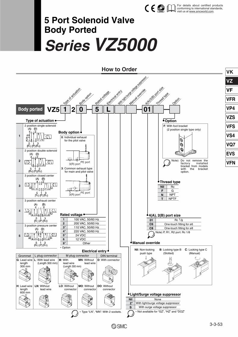
How to Order 5 Port Solenoid Valve Body Ported Series VZ5000 Type of actuation ∗ Option Electrical entry Body option PE port 3(R) port PE port 3(R) port Manual override Thread type Option 4(A), 2(B) port size Nil: Non-locking push type B: Locking type B (Slotted) C: Locking type C (Manual) 1 2 3 ∗ 4 ∗ 5 ∗ 6 9 ∗ ∗ Not available for “GZ”, “HZ” and “DOZ” Light/Surge voltage suppressor Nil None Z ∗ With light/surge voltage suppressor With surge voltage suppressor 1 0 5 01 L Body ported VZ5 2 Type of actuation Rated voltage Body option Electrical entry With light /surge voltage suppressor Manual override Thread type 4(A)/2(B) port size 1 2 position single solenoid 2 2 position double solenoid 3 3 position closed center 4 3 position exhaust center 5 3 position pressure center 100 VAC, 50/60 Hz 200 VAC, 50/60 Hz 110 VAC, 50/60 Hz 220 VAC, 50/60 Hz 24 VDC 12 VDC Other ∗ Type “LN”, “MN”: With 2 sockets. Grommet L plug connector M plug connector DIN terminal S F: With foot bracket (2 position single type only) Option Note) P, R1, R2 port: Rc 1/8 01 C6 C8 One-touch fitting for ø6 One-touch fitting for ø8 Nil Rc F N G NPT T NPTF Rc 1 8 Note) Do not remove the factory installed bracket from models with the bracket option. 0: Individual exhaust for the pilot valve 3: Common exhaust type for main and pilot valve Rated voltage L: With lead wire (Length 300 mm) M: With lead wire (Length 300 mm) MN: Without lead wire D: With connector LN: Without lead wire LO: Without connector MO: Without connector DO: Without connector G: Lead wire length 300 mm H: Lead wire length 600 mm For details about certified products conforming to international standards, visit us at www.smcworld.com. 3-3-53 VK VZ VF VFR VP4 VZS VFS VS4 VQ7 EVS VFN
Transcript
How to Order
5 Port Solenoid ValveBody Ported
Series VZ5000
Type of actuation �
∗ OptionElectrical entry �
Body option �
PE port3(R) port
PE port3(R) port
� Manual override
� Thread type
� Option
� 4(A), 2(B) port size
Nil: Non-lockingpush type
B: Locking type B(Slotted)
C: Locking type C(Manual)
123∗
4∗
5∗
69∗
∗ Not available for “GZ”, “HZ” and “DOZ”
� Light/Surge voltage suppressorNil NoneZ∗ With light/surge voltage suppressor
Grommet L plug connector M plug connector DIN terminal
S
F: With foot bracket(2 position single type only)
Option
Note) P, R1, R2 port: Rc 1/8
01C6C8
One-touch fitting for ø6One-touch fitting for ø8
Nil RcFN
GNPT
T NPTF
Rc 1 8
Note) Do not remove the factory installed bracket from models with the bracket option.
0: Individual exhaust for the pilot valve
3: Common exhaust type for main and pilot valve
Rated voltage �
L: With lead wire (Length 300 mm)
M: With lead wire (Length 300 mm)
MN: Withoutlead wire
D: With connector
LN: Withoutlead wire
LO: Withoutconnector
MO: Withoutconnector
DO: Withoutconnector
G: Lead wirelength300 mm
H: Lead wirelength600 mm
For details about certified products conforming to international standards, visit us at www.smcworld.com.
3-3-53
VK
VZ
VF
VFR
VP4
VZS
VFS
VS4
VQ7
EVS
VFN
Refer to pages 3-3-60 to 3-3-65 for manifold use.
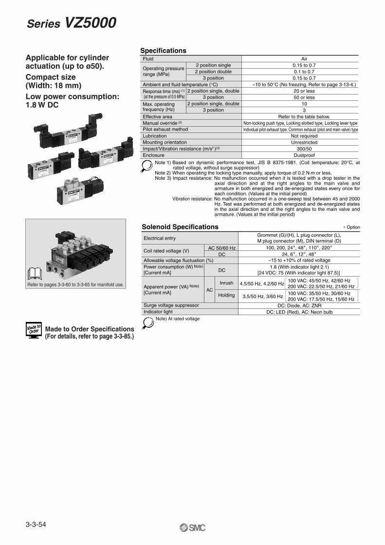
Note 1) Based on dynamic performance test, JIS B 8375-1981. (Coil temperature: 20°C, at rated voltage, without surge suppressor)
Note 2) When operating the locking type manually, apply torque of 0.2 N·m or less.Note 3) Impact resistance: No malfunction occurred when it is tested with a drop tester in the
axial direction and at the right angles to the main valve and armature in both energized and de-energized states every once for each condition. (Values at the initial period)
Vibration resistance: No malfunction occurred in a one-sweep test between 45 and 2000 Hz. Test was performed at both energized and de-energized states in the axial direction and at the right angles to the main valve and armature. (Values at the initial period)
SpecificationsFluid
Operating pressurerange (MPa)
Ambient and fluid temperature (°C)Response time (ms) (1)
(at the pressure of 0.5 MPa)
Max. operatingfrequency (Hz)
Manual override (2)
Pilot exhaust methodLubricationMounting orientationImpact/Vibration resistance (m/s2 )(3)
Enclosure
2 position single
2 position single, double
2 position double3 position
3 position2 position single, double
3 position
Air0.15 to 0.70.1 to 0.70.15 to 0.7
–10 to 50°C (No freezing. Refer to page 3-13-4.)20 or less50 or less
103
Non-locking push type, Locking slotted type, Locking lever typeEffective area Refer to the table below.
Individual pilot exhaust type, Common exhaust (pilot and main valve) typeNot requiredUnrestricted
300/50Dustproof
Note) At rated voltage
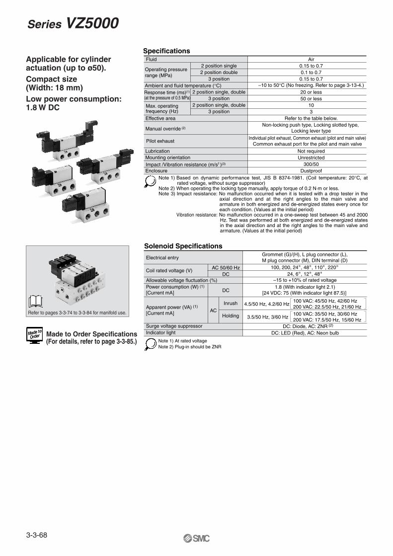
Applicable for cylinder actuation (up to ø50).Compact size (Width: 18 mm)Low power consumption: 1.8 W DC
Power consumption (W)[Current mA]
Solenoid Specifications ∗ Option
Electrical entry
Coil rated voltage (V)
Allowable voltage fluctuation (%)
AC 50/60 HzDC
DC
AC
Grommet (G)/(H), L plug connector (L),M plug connector (M), DIN terminal (D)
100, 200, 24∗, 48∗, 110∗, 220∗24, 6∗, 12∗, 48∗
–15 to +10% of rated voltage1.8 (With indicator light 2.1)
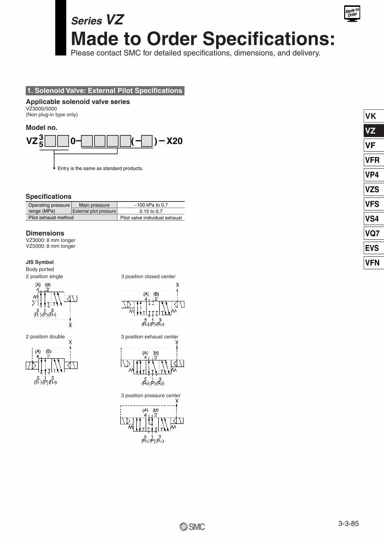
Made to Order Specifications(For details, refer to page 3-3-85.)
Series VZ5000
3-3-54
VK
VZ
VF
VFR
VP4
VZS
VFS
VS4
VQ7
EVS
VFN
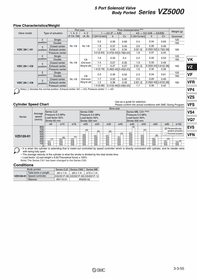
∗ It is when the cylinder is extending that is meter-out controlled by speed controller which is directly connected with cylinder, and its needle valve with being fully open.
∗ The average velocity of the cylinder is what the stroke is divided by the total stroke time.∗ Load factor: ((Load weight x 9.8)/Theoretical force) x 100%Note) The Series CA1 has been changed to the Series CA2.
Use as a guide for selection.Please confirm the actual conditions with SMC Sizing Program.
2position
3position
2position
3position
2position
3position
C [dm3/(s·bar)]
2.2
1.81.2
3.0 [0.83]
1.6
1.41.1
1.8 [0.78]
2.0
1.71.2
1.9 [0.86]
b
0.36
0.370.50
0.37[0.50]
0.33
0.270.37
0.36[0.40]
0.39
0.350.38
0.57[0.46]
Cv
0.58
0.450.34
0.78[0.25]
0.4
0.350.27
0.45[0.22]
0.52
0.420.33
0.59[0.25]
Weight (g)
Grommet120160
160
120160
160
120160
160
Port sizeValve model Type of actuation
VZ5�20-�-01
VZ5�20-�-C6
VZ5�20-�-C8
SingleDouble
Closed centerExhaust centerPressure center
SingleDouble
Closed centerExhaust centerPressure center
SingleDouble
Closed centerExhaust centerPressure center
C [dm3/(s·bar)]
2.4
2.03.0[1.3]
1.8
2.2
1.92.5[1.3]
1.6
2.3
2.02.6[1.3]
1.7
b
0.34
0.350.35[0.52]
0.37
0.32
0.330.32[0.54]
0.30
0.34
0.290.35[0.49]
0.39
Cv
0.63
0.490.73[0.39]
0.45
0.53
0.490.61[0.38]
0.39
0.61
0.490.67[0.38]
0.42
1 � 4/2 (P � A/B)4, 2(A, B)
1, 5, 3(P, EA, EB)
4/2 � 5/3 (A/B � EA/EB)
Note) [ ]: Denotes the normal position. Exhaust center: 4/2 � 5/3, Pressure center: 1 � 4/2
Rc 1/8Rc 1/8
Rc 1/8
Rc 1/8
C6(One-touch
fitting for ø6)
C8(One-touch
fitting for ø8)
Flow Characteristics/Weight
Cylinder Speed Chart
VZ5120-01
Body portedTube bore x LengthSpeed controllerSilencer
Series CJ2 Series CM2ø6 x 1 m
AS3301F-06ø12 x 1 m
AS4001F-12AN200-02
ø6 x 1 mAS2301F-06AN110-01
Series MB
Series
VZ5120-01
Averagespeed(mm/s)
Bore sizeSeries CJ2Pressure 0.5 MPaLoad factor 50%Stroke 60 mm
Series CM2Pressure 0.5 MPaLoad factor 50%Stroke 300 mm
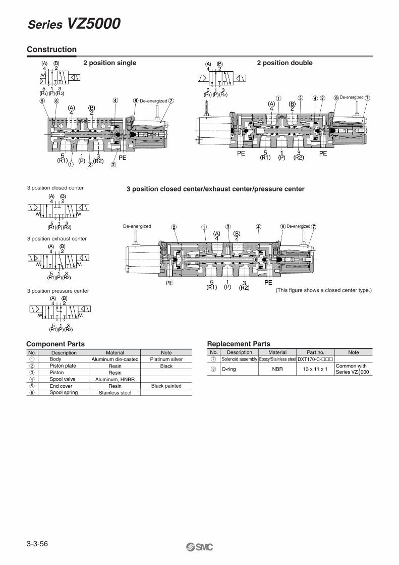
3 position closed center/exhaust center/pressure center3 position closed center
3 position exhaust center
3 position pressure center
Component Parts
i
DXT170-C-���u
Common with Series VZ 0001
3
Construction
Replacement PartsNo. Description Material Part no. Note
Solenoid assembly Epoxy/Stainless steel
O-ring NBR 13 x 11 x 1
(This figure shows a closed center type.)
De-energizedDe-energized
De-energizedDe-energized
Series VZ5000
3-3-56
VK
VZ
VF
VFR
VP4
VZS
VFS
VS4
VQ7
EVS
VFN
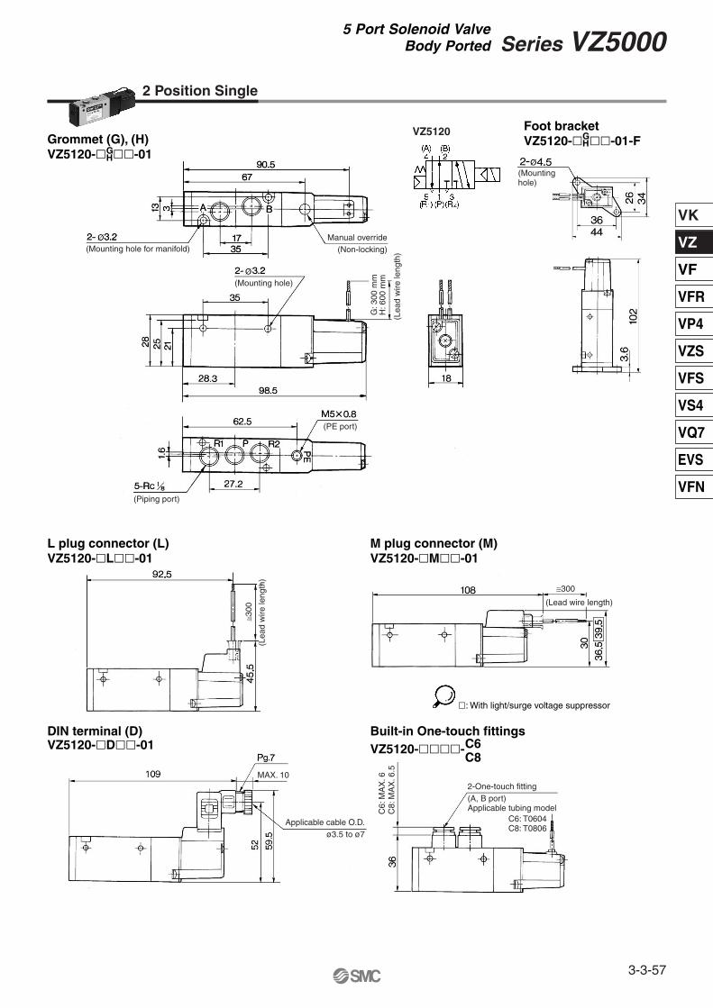
2 Position Single
L plug connector (L)VZ5120-�L��-01
VZ5120Grommet (G), (H)VZ5120-� ��-01
M plug connector (M)VZ5120-�M��-01
DIN terminal (D)VZ5120-�D��-01
Foot bracketVZ5120-� ��-01-F
Built-in One-touch fittingsVZ5120-����-C6
C8
GH
GH
(Mounting hole)
(Mountinghole)
Manual override(Non-locking)
G: 3
00 m
mH
: 600
mm
(Lea
d w
ire le
ngth
)
(PE port)
(Piping port)
≅300
(Lea
d w
ire le
ngth
)
≅300
(Lead wire length)
Applicable cable O.D.ø3.5 to ø7
(Mounting hole for manifold)
2-One-touch fitting(A, B port)Applicable tubing modelC
6: M
AX
. 6C
8: M
AX
. 6.5
MAX. 10
C6: T0604C8: T0806
�: With light/surge voltage suppressor
3-3-57
Series VZ50005 Port Solenoid Valve
Body Ported
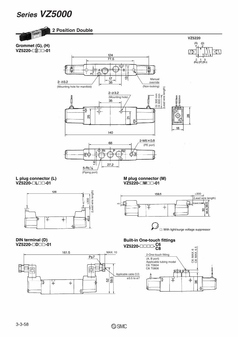
Grommet (G), (H)VZ5220-� ��-01
2 Position Double
GH
L plug connector (L)VZ5220-�L��-01
VZ5220
M plug connector (M)VZ5220-�M��-01
DIN terminal (D)VZ5220-�D��-01
Built-in One-touch fittingsVZ5220-����-C6
C8
(Mounting hole)
Manualoverride
(Non-locking)
G: 3
00 m
mH
: 600
mm
(PE port)
(Piping port)
(Mounting hole for manifold)≅3
00
(Lea
d w
ire le
ngth
)
≅300
(Lead wire length)
2-One-touch fitting(A, B port)Applicable tubing model C
6: M
AX
. 6C
8: M
AX
. 6.5
MAX. 10
C6: T0604C8: T0806
Applicable cable O.D.ø3.5 to ø7
(Lea
d w
ire le
ngth
)
�: With light/surge voltage suppressor
Series VZ5000
3-3-58
VK
VZ
VF
VFR
VP4
VZS
VFS
VS4
VQ7
EVS
VFN
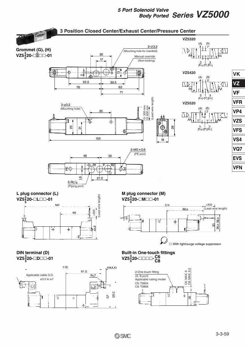
3 Position Closed Center/Exhaust Center/Pressure Center
L plug connector (L)VZ5 20-�L��-01
M plug connector (M)VZ5 20-�M��-01
Built-in One-touch fittingsVZ5 20-����-
DIN terminal (D)VZ5 20-�D��-01
Grommet (G), (H)VZ5 20-� ��-01G
H
345
345
345
345
VZ5320
VZ5420
VZ5520
C6C8
345
(Mounting hole)
Manual override(Non-locking)
G: 3
00 m
mH
: 600
mm
(PE port)
(Piping port)
(Mounting hole for manifold)
(Lea
d w
ire le
ngth
)
≅300
(Lea
d w
ire le
ngth
)
≅300(Lead wire length)
2-One-touch fitting(A, B port)Applicable tubing modelC6: T0604C8: T0806
Applicable cable O.D.ø3.5 to ø7
�: With light/surge voltage suppressor
C6:
MA
X. 6
C8:
MA
X. 6
.5
3-3-59
Series VZ50005 Port Solenoid Valve
Body Ported
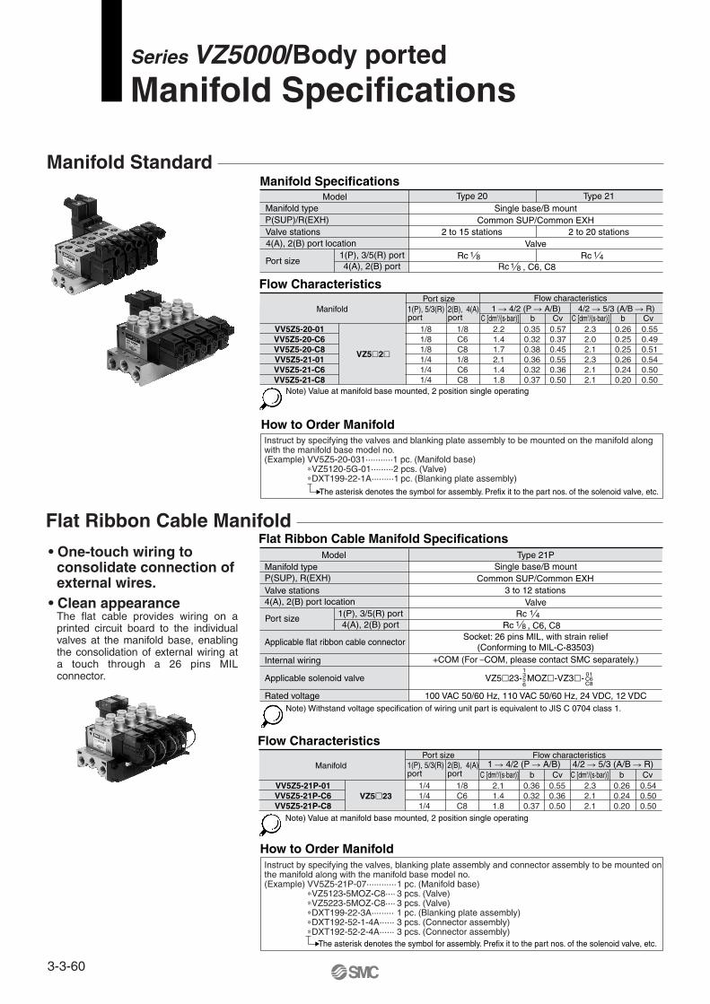
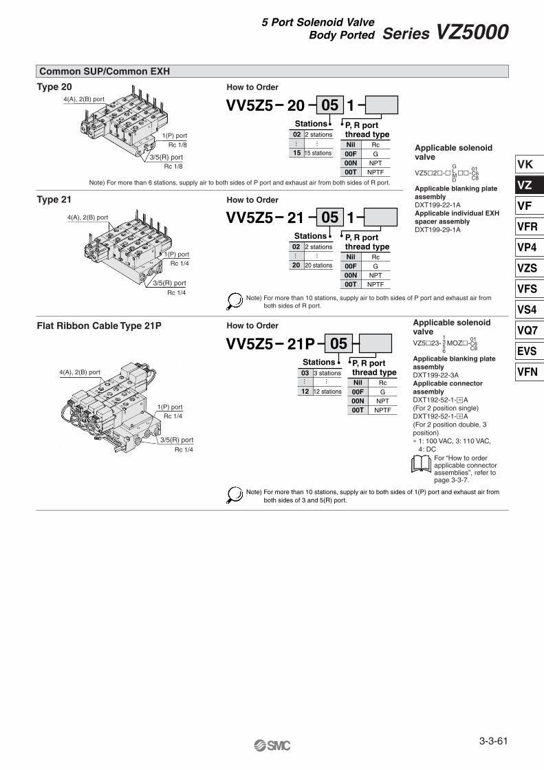
Flat Ribbon Cable Manifold
• One-touch wiring to consolidate connection of external wires.
• Clean appearanceThe flat cable provides wiring on a printed circuit board to the individual valves at the manifold base, enabling the consolidation of external wiring at a touch through a 26 pins MIL connector.
Note) Withstand voltage specification of wiring unit part is equivalent to JIS C 0704 class 1.
Note) Value at manifold base mounted, 2 position single operating
Note) Value at manifold base mounted, 2 position single operating
VZ5�23- MOZ�-VZ3�- 1356
Manifold Specifications
Flat Ribbon Cable Manifold Specifications
ModelManifold typeP(SUP)/R(EXH)Valve stations4(A), 2(B) port location
Port size
Type 20 Type 21Single base/B mount
Common SUP/Common EXH
ValveRc
RcRc
2 to 15 stations 2 to 20 stations
1 8
, C6, C81 8
1 41(P), 3/5(R) port4(A), 2(B) port
1(P), 3/5(R) port4(A), 2(B) port
ModelManifold typeP(SUP), R(EXH)Valve stations4(A), 2(B) port location
Internal wiring
Applicable flat ribbon cable connector
Applicable solenoid valve
Rated voltage
Port size
Type 21PSingle base/B mount
+COM (For –COM, please contact SMC separately.)
Socket: 26 pins MIL, with strain relief(Conforming to MIL-C-83503)
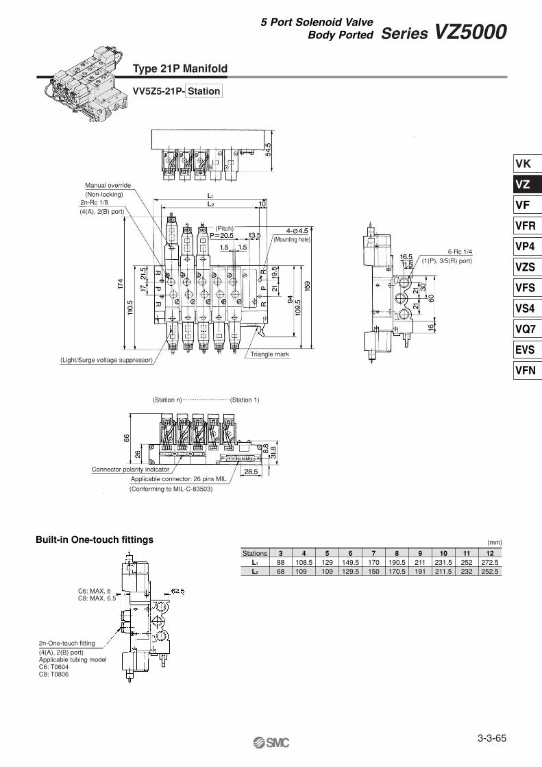
How to Order ManifoldInstruct by specifying the valves, blanking plate assembly and connector assembly to be mounted on the manifold along with the manifold base model no. (Example) VV5Z5-21P-07············1 pc. (Manifold base)
The asterisk denotes the symbol for assembly. Prefix it to the part nos. of the solenoid valve, etc.
How to Order ManifoldInstruct by specifying the valves and blanking plate assembly to be mounted on the manifold along with the manifold base model no. (Example) VV5Z5-20-031···········1 pc. (Manifold base)
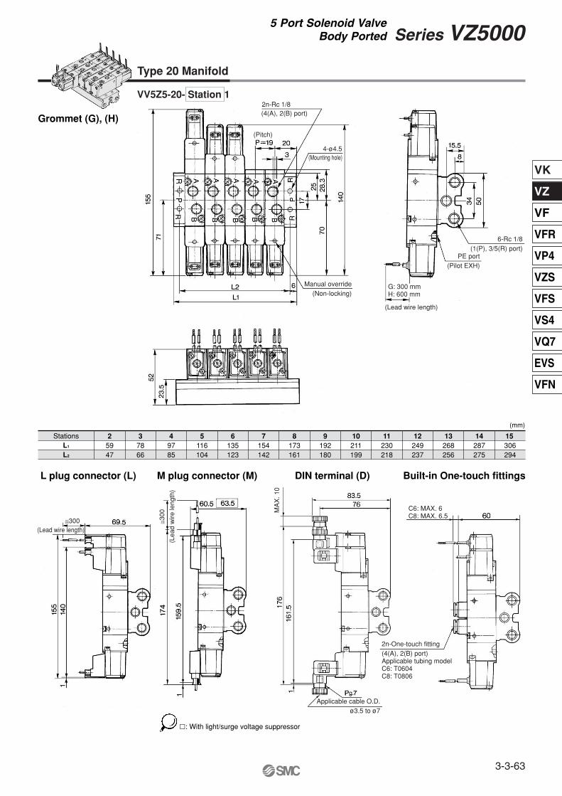
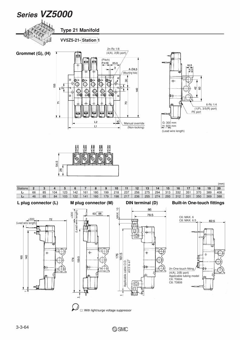
Note) For more than 10 stations, supply air to both sides of P port and exhaust air from both sides of R port.
3-3-61
Series VZ50005 Port Solenoid Valve
Body Ported
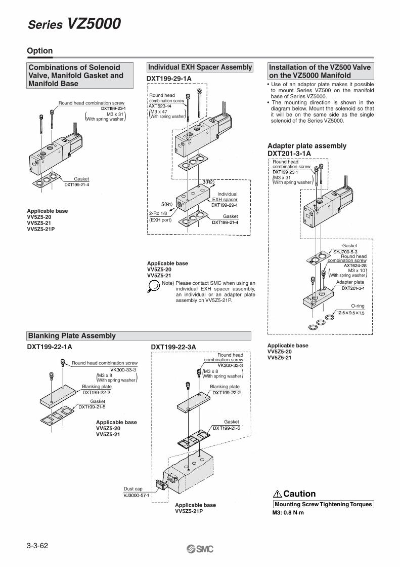
CautionMounting Screw Tightening Torques
M3: 0.8 N·mApplicable baseVV5Z5-21P
Round headcombination screw
Gasket
Dust cap
Blanking plate
( )
( )
Blanking Plate Assembly
Option
Applicable baseVV5Z5-20VV5Z5-21
• Use of an adaptor plate makes it possible to mount Series VZ500 on the manifold base of Series VZ5000.
• The mounting direction is shown in the diagram below. Mount the solenoid so that it will be on the same side as the single solenoid of the Series VZ5000.
DXT199-22-1A
Applicable baseVV5Z5-20VV5Z5-21VV5Z5-21P
Applicable baseVV5Z5-20VV5Z5-21
Adapter plate assemblyDXT201-3-1A
DXT199-22-3A
Applicable baseVV5Z5-20VV5Z5-21
Note) Please contact SMC when using an individual EXH spacer assembly, an individual or an adapter plate assembly on VV5Z5-21P.
Combinations of Solenoid Valve, Manifold Gasket and Manifold Base
DXT199-29-1A
Individual EXH Spacer Assembly Installation of the VZ500 Valve on the VZ5000 Manifold
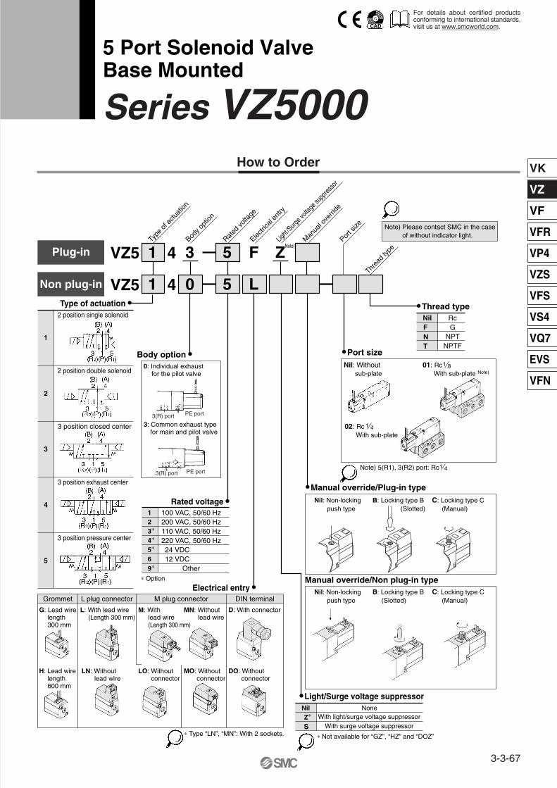
∗ Type “LN”, “MN”: With 2 sockets. ∗ Not available for “GZ”, “HZ” and “DOZ”
� Light/Surge voltage suppressorNil NoneZ∗ With light/surge voltage suppressor
With surge voltage suppressorS
� Thread typeNilFNT
1 0 5 LNon plug-in VZ5 4
1 3 5 F ZPlug-in VZ5 4Ty
pe o
f actu
ation
Rated
volta
ge
Body o
ption
Electri
cal e
ntry
Light/
Surge v
oltag
e sup
press
or
Man
ual o
verri
de
Port s
ize
1
2 position single solenoid
2
2 position double solenoid
3
3 position closed center
4
3 position exhaust center
5
3 position pressure center
Grommet L plug connector M plug connector DIN terminal
Nil: Withoutsub-plate
Note)
Note) 5(R1), 3(R2) port: Rc
01: RcWith sub-plate Note)
� Port size
Manual override/Non plug-in type
1 8
02: RcWith sub-plate
1 4
1 4
Threa
d typ
e
RcG
NPTNPTF
0
1
0
1
0: Individual exhaustfor the pilot valve
3: Common exhaust type for main and pilot valve
Note) Please contact SMC in the caseof without indicator light.
3(R) port
3(R) port PE port
PE port
L: With lead wire (Length 300 mm)
M: With lead wire (Length 300 mm)
MN: Withoutlead wire
D: With connector
LN: Withoutlead wire
LO: Withoutconnector
MO: Withoutconnector
DO: Withoutconnector
G: Lead wirelength300 mm
H: Lead wirelength600 mm
For details about certified products conforming to international standards, visit us at www.smcworld.com.
3-3-67
VK
VZ
VF
VFR
VP4
VZS
VFS
VS4
VQ7
EVS
VFN
Note 1) Based on dynamic performance test, JIS B 8374-1981. (Coil temperature: 20°C, at rated voltage, without surge suppressor)
Note 2) When operating the locking type manually, apply torque of 0.2 N·m or less.Note 3) Impact resistance: No malfunction occurred when it is tested with a drop tester in the
axial direction and at the right angles to the main valve and armature in both energized and de-energized states every once for each condition. (Values at the initial period)
Vibration resistance: No malfunction occurred in a one-sweep test between 45 and 2000 Hz. Test was performed at both energized and de-energized states in the axial direction and at the right angles to the main valve and armature. (Values at the initial period)
Operating pressurerange (MPa)
Response time (ms)(1)
(at the pressure of 0.5 MPa)
Max. operatingfrequency (Hz)
Manual override (2)
Impact /Vibration resistance (m/s2 )(3)
SpecificationsFluid
Ambient and fluid temperature (°C)
Effective area
Pilot exhaust
LubricationMounting orientation
Enclosure
2 position single
2 position single, double
2 position double3 position
3 position2 position single, double
3 position
Air0.15 to 0.70.1 to 0.70.15 to 0.7
–10 to 50°C (No freezing. Refer to page 3-13-4.)20 or less50 or less
103
Refer to the table below.Non-locking push type, Locking slotted type,
Locking lever type
Individual pilot exhaust, Common exhaust (pilot and main valve)Common exhaust port for the pilot and main valve
Not requiredUnrestricted
300/50Dustproof
Refer to pages 3-3-74 to 3-3-84 for manifold use.
Note 1) At rated voltageNote 2) Plug-in should be ZNR
Power consumption (W)[Current mA]
Solenoid Specifications
Electrical entry
Coil rated voltage (V)
Allowable voltage fluctuation (%)
AC 50/60 HzDC
DC
AC
Grommet (G)/(H), L plug connector (L),M plug connector (M), DIN terminal (D)
100, 200, 24∗, 48∗, 110∗, 220∗24, 6∗, 12∗, 48∗
–15 to +10% of rated voltage1.8 (With indicator light 2.1)
Applicable for cylinder actuation (up to ø50).Compact size (Width: 18 mm)Low power consumption: 1.8 W DC
Made to Order Specifications(For details, refer to page 3-3-85.)
Series VZ5000
3-3-68
VK
VZ
VF
VFR
VP4
VZS
VFS
VS4
VQ7
EVS
VFN
∗ It is when the cylinder is extending that is meter-out controlled by speed controller which is directly connected withcylinder, and its needle valve with being fully open.
∗ The average velocity of the cylinder is what the stroke is divided by the total stroke time.∗ Load factor: ((Load weight x 9.8)/Theoretical force) x 100%
Use as a guide for selection.Please confirm the actual conditions with SMC Sizing Program.
2position
3position
2position
3position
Series
Speed controller/Silencer
Speed controller/Silencer
AS3301F-�02-06�/AN200-2
AS3301F-�02-08�/AN200-2
VZ514�-����-02�(Piping: ø6 x 1 m)
VZ514�-����-02�(Piping: ø8 x 1 m)
Averagespeed(mm/s)
Bore size
Series CA1 Note) The CA1 series has been changed to the CA2 series.Pressure 0.5 MPaLoad factor 50%Stroke 500 mm
ø40 ø50 ø63 ø80 ø100800700600500400300200100
800700600500400300200100
Speed controller/Silencer AS3301F-�02-10�/AN200-2
VZ514�-����-02�(Piping: ø10 x 1 m)
800700600500400300200100
Speed controller/Silencer AS4001F-�02-12�/AN200-2
VZ514�-����-02�(Piping: ø12 x 1 m)
800700600500400300200100
C [dm3/(s·bar)]
2.3
1.91.2
3.3[0.85]
2.3
1.91.3
3.6[0.83]
b
0.45
0.360.48
0.43[0.54]
0.41
0.460.45
0.23[0.55]
Cv
0.57
0.480.35
0.78[0.25]
0.61
0.500.35
0.84[0.25]
Weight (g)
Grommet200(120)240(160)
240(160)
200(120)240(160)
240(160)
Port sizeValve model Type of actuation
VZ5�40-�-01
VZ5�40-�-02
SingleDouble
Closed centerExhaust centerPressure center
SingleDouble
Closed centerExhaust centerPressure center
C [dm3/(s·bar)]
2.8
2.13.4[1.3]
2.1
2.9
2.23.7[1.4]
2.1
b
0.37
0.460.36[0.57]
0.45
0.35
0.440.27[0.56]
0.47
Cv
0.71
0.570.86[0.41]
0.56
0.74
0.600.87[0.43]
0.58
Flow characteristics (1)
1 � 4/2 (P � A/B)4, 2(A, B)
1, 5, 3(P, EA, EB)
4/2 � 5/3 (A/B � EA/EB)
Note 1) [ ]: Denotes the normal position. Exhaust center: 4/2 � 5/3, Pressure center: 1 � 4/2Note 2) ( ): Without sub-plate.
3 position closed center/exhaust center/pressure center3 position closed center
3 position exhaust center
3 position pressure center
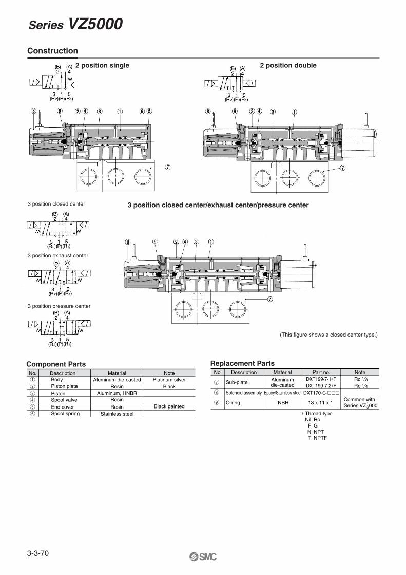
Component Parts
Construction
Replacement PartsNo. Description Material Part no. Note
Solenoid assembly Epoxy/Stainless steel
O-ring NBR 13 x 11 x 1
Sub-plate Aluminumdie-casted
DXT199-7-1∗PDXT199-7-2∗P
Rc 1 8
Rc 1 4
(This figure shows a closed center type.)
i
o
DXT170-C-���
u
Common with Series VZ 0001
3
∗ Thread typeNil: Rc F: G N: NPT T: NPTF
Series VZ5000
3-3-70
VK
VZ
VF
VFR
VP4
VZS
VFS
VS4
VQ7
EVS
VFN
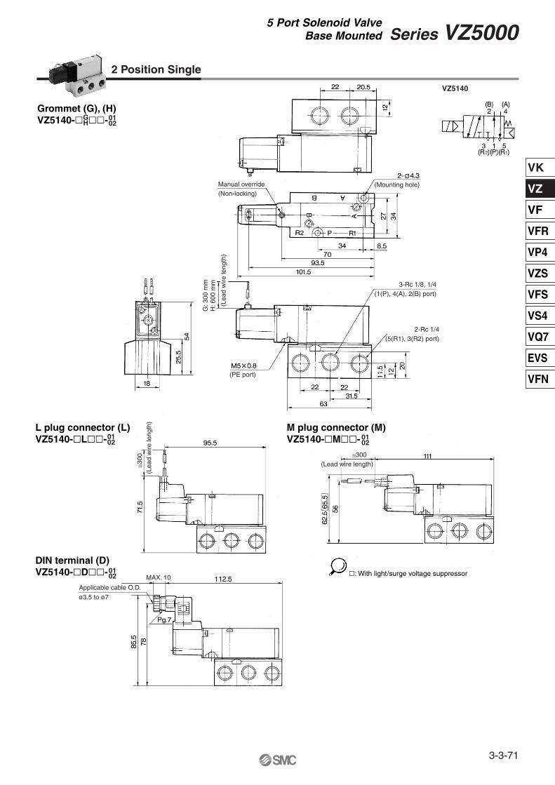
VZ5140
Grommet (G), (H)VZ5140-� ��-01
02
L plug connector (L)VZ5140-�L��-
M plug connector (M)VZ5140-�M��-
2 Position Single
GH
0102
0102
0102
DIN terminal (D)VZ5140-�D��- �: With light/surge voltage suppressor
Manual override(Non-locking)
(Mounting hole)
(PE port)
≅300 ≅300
(Lead wire length)
Applicable cable O.D.
ø3.5 to ø7
MAX. 10
(Lea
d w
ire le
ngth
)
(Lea
d w
ire le
ngth
)
G: 3
00 m
mH
: 600
mm 3-Rc 1/8, 1/4
(1(P), 4(A), 2(B) port)
2-Rc 1/4(5(R1), 3(R2) port)
3-3-71
Series VZ50005 Port Solenoid Valve
Base Mounted
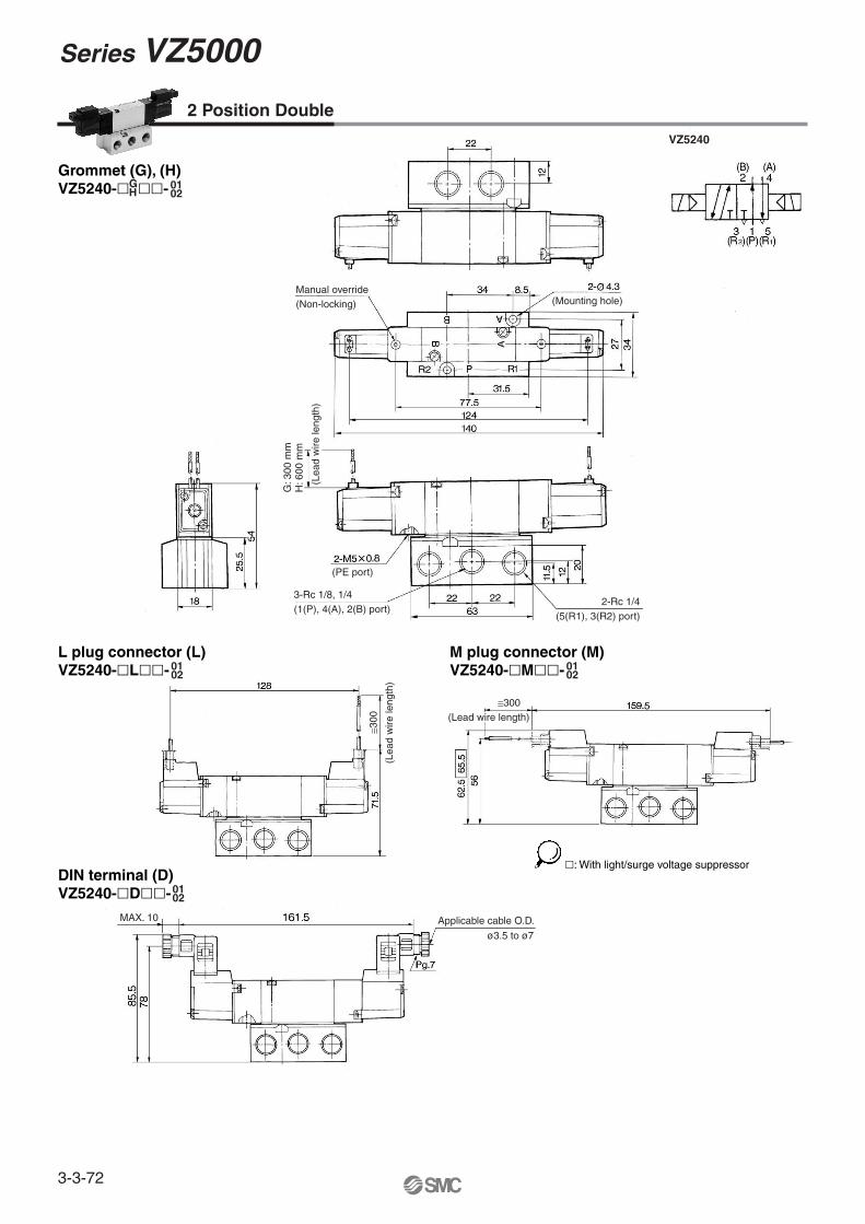
VZ5240
Grommet (G), (H)VZ5240-� ��-
L plug connector (L)VZ5240-�L��-
DIN terminal (D)VZ5240-�D��-
M plug connector (M)VZ5240-�M��-
0102
2 Position Double
GH
0102
0102
0102
�: With light/surge voltage suppressor
Manual override(Non-locking) (Mounting hole)
(PE port)
≅300
≅300(Lead wire length)
Applicable cable O.D.
ø3.5 to ø7
MAX. 10
(Lea
d w
ire le
ngth
)
(Lea
d w
ire le
ngth
)
G: 3
00 m
mH
: 600
mm
3-Rc 1/8, 1/4(1(P), 4(A), 2(B) port)
2-Rc 1/4(5(R1), 3(R2) port)
Series VZ5000
3-3-72
VK
VZ
VF
VFR
VP4
VZS
VFS
VS4
VQ7
EVS
VFN
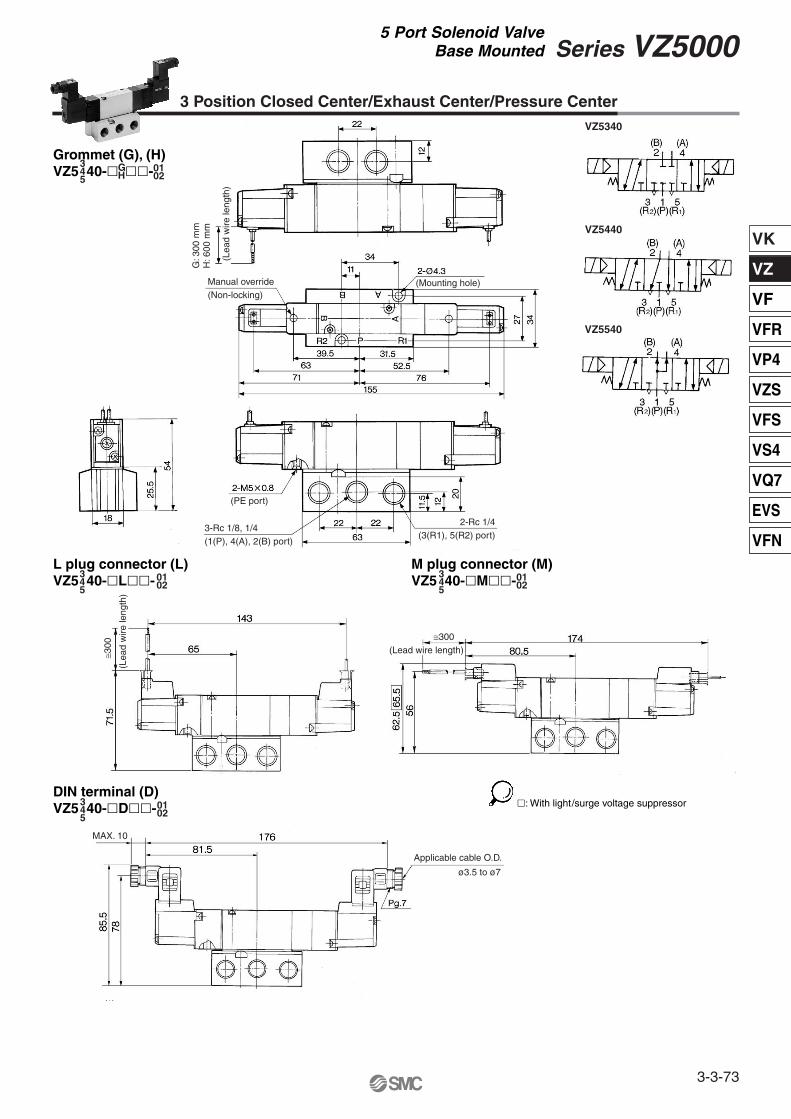
DIN terminal (D)VZ5 40-�D��-
L plug connector (L)VZ5 40-�L��-
Grommet (G), (H)VZ5 40-� ��-
3 Position Closed Center/Exhaust Center/Pressure Center
0102
�: With light/surge voltage suppressor
VZ5340
VZ5440
VZ5540
M plug connector (M)VZ5 40-�M��-
345
GH
0102
345
0102
345
0102
345
Manual override(Non-locking)
(Mounting hole)
(PE port)
≅300
≅300(Lead wire length)
Applicable cable O.D.
ø3.5 to ø7
MAX. 10
(Lea
d w
ire le
ngth
)
(Lea
d w
ire le
ngth
)
G: 3
00 m
mH
: 600
mm
3-Rc 1/8, 1/4(1(P), 4(A), 2(B) port)
2-Rc 1/4(3(R1), 5(R2) port)
3-3-73
Series VZ50005 Port Solenoid Valve
Base Mounted
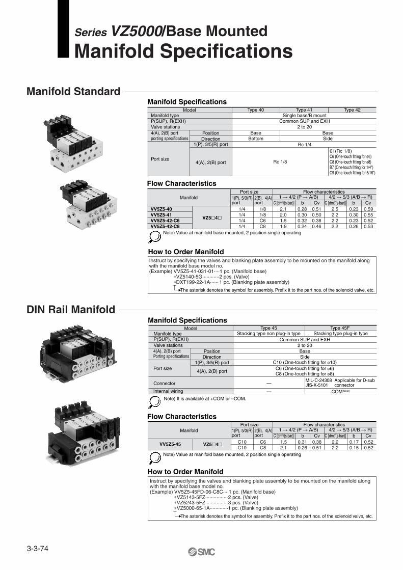
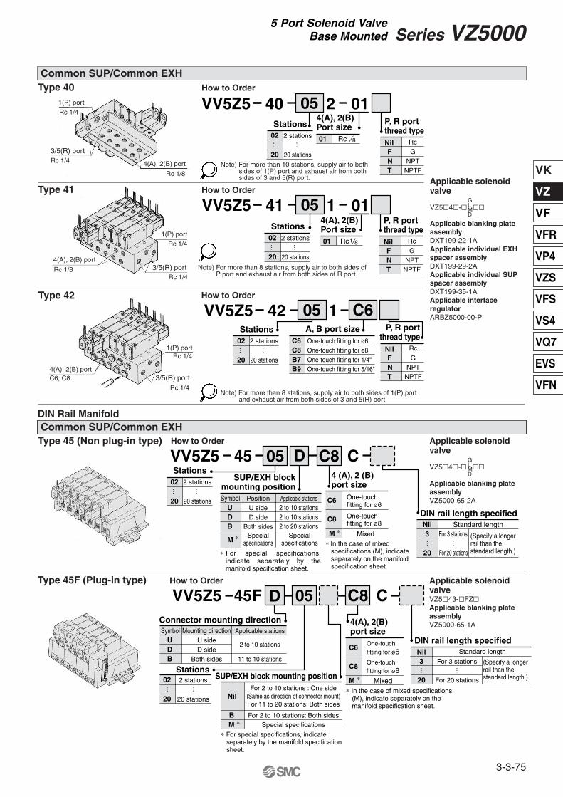
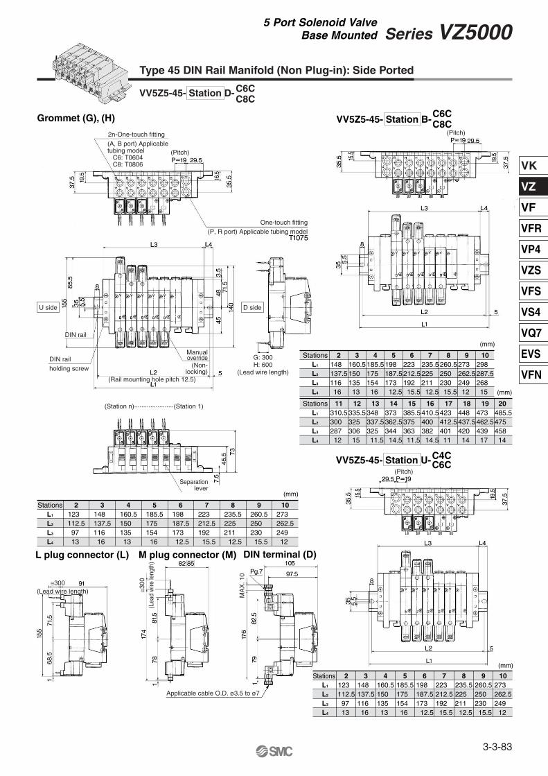
Manifold Standard
DIN Rail Manifold
Note) Value at manifold base mounted, 2 position single operating
Note) Value at manifold base mounted, 2 position single operating
How to Order Manifold
How to Order Manifold
Manifold Specifications
Instruct by specifying the valves and blanking plate assembly to be mounted on the manifold along with the manifold base model no. (Example) VV5Z5-41-031-01····1 pc. (Manifold base)
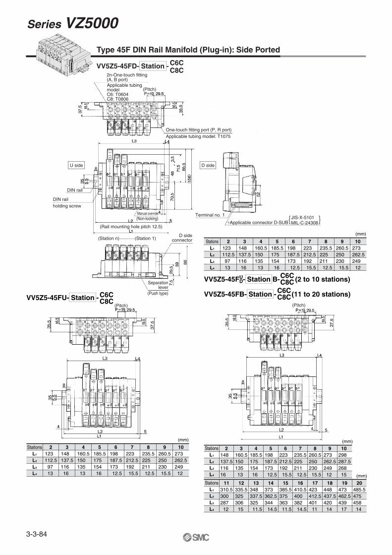
Instruct by specifying the valves and blanking plate assembly to be mounted on the manifold along with the manifold base model no. (Example) VV5Z5-45FD-06-C8C····1 pc. (Manifold base)
Note) For more than 8 stations, supply air to both sides of P port and exhaust air from both sides of R port.
Note) For more than 8 stations, supply air to both sides of 1(P) port and exhaust air from both sides of 3 and 5(R) port.
DIN rail length specified
4 (A), 2 (B)port size
Nil Standard length
(Specify a longerrail than thestandard length.)
3
20
For 3 stations
For 20 stations
One-touchfitting for ø6
One-touchfitting for ø8
Mixed
C6
C8
M ∗
SUP/EXH blockmounting position
∗ For special specifications, indicate separately by the manifold specification sheet.
∗ In the case of mixed specifications (M), indicate separately on the manifold specification sheet.
CD45 05 C8VV5Z5
Symbol Position Applicable stations2 to 10 stations
DU
B 2 to 20 stations2 to 10 stationsD side
U side
Both sides
M ∗ Specialspecifications
Specialspecifications
Symbol Mounting direction Applicable stations
2 to 10 stationsDU
B 11 to 10 stationsD sideU side
Both sides
Stations P, R portthread type
Rc
NPT
Nil
NNPTFT
GF
······
2 stations
20 stations
02
20
Stations
······
2 stations
20 stations
02
20
Stations
······
2 stations
20 stations
02
20
Stations
······
······
4(A), 2(B) port
1(P) portRc 1/4
1(P) port
Rc 1/4
1(P) port
Rc 1/4
Rc 1/4
Rc 1/8
4(A), 2(B) port
4(A), 2(B) port
Rc 1/8
3/5(R) port
Rc 1/43/5(R) port
3/5(R) portRc 1/4
4(A), 2(B) port size
Stations
One-touchfitting for ø6
One-touchfitting for ø8
SUP/EXH block mounting position
∗ For special specifications, indicate separately by the manifold specification sheet.
∗ In the case of mixed specifications (M), indicate separately on the manifold specification sheet.
2 stations
20 stations NilFor 2 to 10 stations : One side
(Same as direction of connector mount)For 11 to 20 stations: Both sides
For 2 to 10 stations: Both sidesSpecial specificationsM ∗
B
02
20
Connector mounting direction
CD45F 05 C8VV5Z5
Mixed
C6
C8
M ∗
DIN rail length specifiedNil Standard length
(Specify a longerrail than thestandard length.)
3
20
For 3 stations
For 20 stations
······
······
C6, C8
Applicable solenoid valve
VZ5�4�-� ��
Applicable blanking plate assemblyVZ5000-65-2A
3-3-75
Series VZ50005 Port Solenoid Valve
Base Mounted
2-Rc 1/8
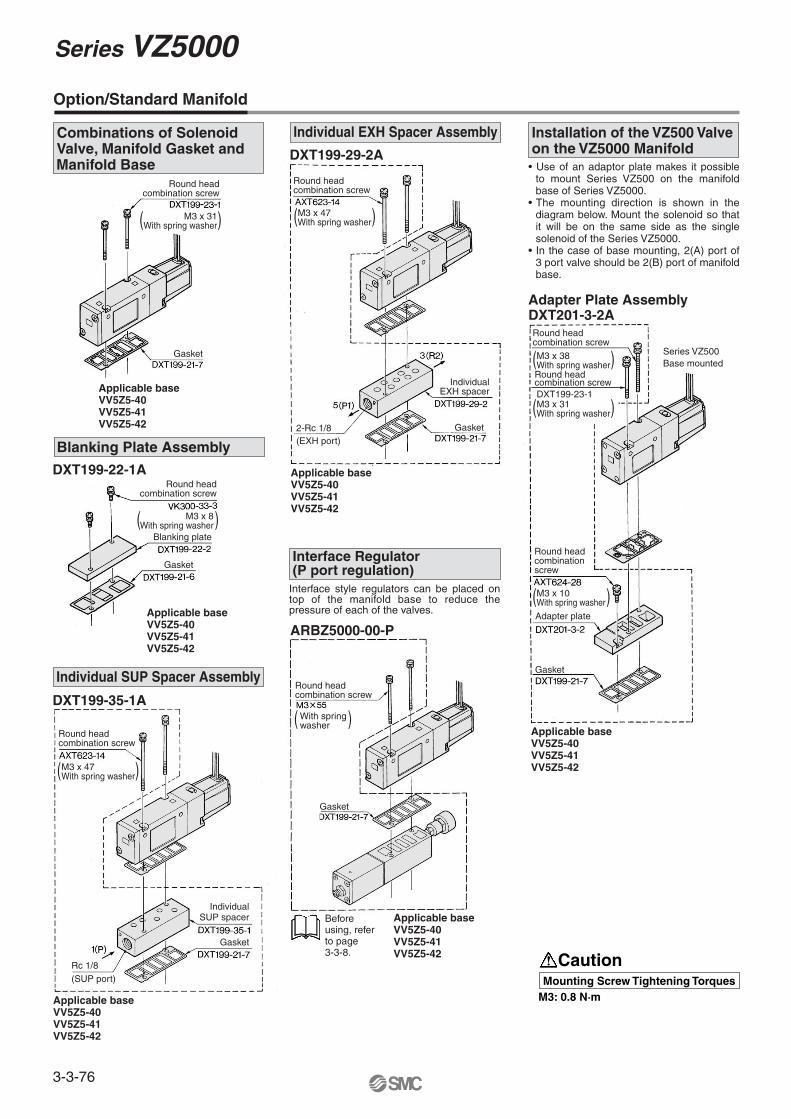
Option/Standard Manifold
Interface Regulator (P port regulation)
DXT199-29-2A• Use of an adaptor plate makes it possible
to mount Series VZ500 on the manifold base of Series VZ5000.
• The mounting direction is shown in the diagram below. Mount the solenoid so that it will be on the same side as the single solenoid of the Series VZ5000.
• In the case of base mounting, 2(A) port of 3 port valve should be 2(B) port of manifold base.
DXT199-22-1A
Applicable baseVV5Z5-40VV5Z5-41VV5Z5-42
Adapter Plate AssemblyDXT201-3-2A
Applicable baseVV5Z5-40VV5Z5-41VV5Z5-42
DXT199-35-1A
Applicable baseVV5Z5-40VV5Z5-41VV5Z5-42
Applicable baseVV5Z5-40VV5Z5-41VV5Z5-42
Interface style regulators can be placed on top of the manifold base to reduce the pressure of each of the valves.
ARBZ5000-00-P
Applicable baseVV5Z5-40VV5Z5-41VV5Z5-42
Applicable baseVV5Z5-40VV5Z5-41VV5Z5-42
Before using, refer to page 3-3-8.
Combinations of Solenoid Valve, Manifold Gasket and Manifold Base
Blanking Plate Assembly
Individual SUP Spacer Assembly
Individual EXH Spacer Assembly Installation of the VZ500 Valve on the VZ5000 Manifold
Round headcombination screw
Round headcombination screw
Round headcombination screw
Round headcombinationscrew
Round headcombination screw
Round headcombination screw
Gasket
Gasket
Gasket
Round headcombination screw
Gasket
Gasket
Gasket
IndividualSUP spacer
Blanking plate
Round headcombination screw
Rc 1/8(SUP port)
(EXH port)
IndividualEXH spacer
Series VZ500Base mounted
Adapter plate
( )M3 x 31With spring washer
( )M3 x 47With spring washer
( )M3 x 38With spring washer
( )M3 x 10With spring washer
( )M3 x 31With spring washer
( )M3 x 8With spring washer
( )M3 x 47With spring washer
( )With springwasher
CautionMounting Screw Tightening Torques
M3: 0.8 N·m
DXT199-23-1
Series VZ5000
3-3-76
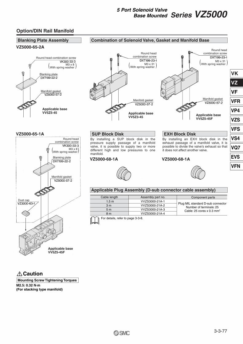
Applicable baseVV5Z5-45
VZ5000-65-2A
VZ5000-68-1A
VZ5000-65-1A
Applicable baseVV5Z3-45
Applicable baseVV5Z5-45F
VZ5000-68-1A
Applicable baseVV5Z5-45F
CautionMounting Screw Tightening Torques
For details, refer to page 3-3-8.
Blanking Plate Assembly
Option/DIN Rail Manifold
Combination of Solenoid Valve, Gasket and Manifold Base
By installing a SUP block disk in the pressure supply passage of a manifold valve, it is possible to supply two or more different high and low pressures to one manifold.
SUP Block DiskBy installing an EXH block disk in the exhaust passage of a manifold valve, it is possible to divide the valve’s exhaust so that it does not affect another valve.
EXH Block Disk
Cable length1.5 m3 m5 m8 m
Assembly part no. Component parts
Plug MIL standard D-sub connectorNumber of terminals: 25
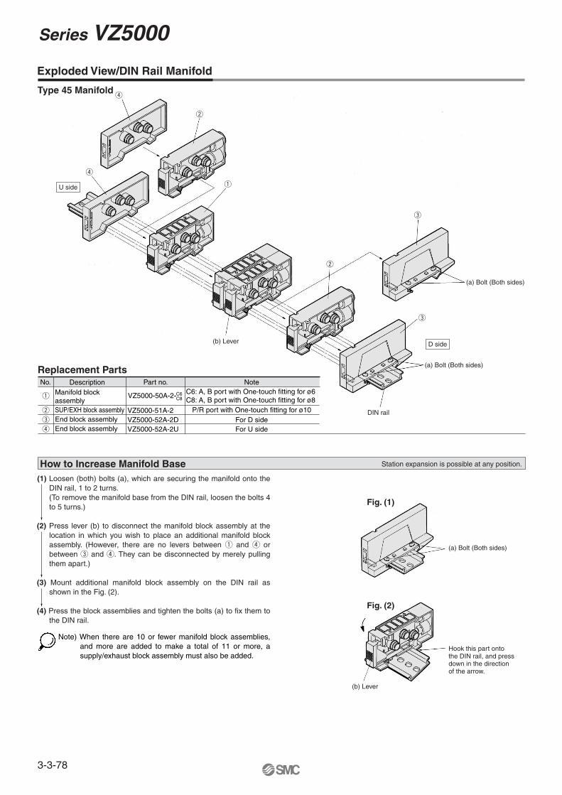
How to Increase Manifold Base(1) Loosen (both) bolts (a), which are securing the manifold onto the
DIN rail, 1 to 2 turns. (To remove the manifold base from the DIN rail, loosen the bolts 4 to 5 turns.)
(2) Press lever (b) to disconnect the manifold block assembly at the location in which you wish to place an additional manifold block assembly. (However, there are no levers between q and r or between e and r. They can be disconnected by merely pulling them apart.)
(3) Mount additional manifold block assembly on the DIN rail as shown in the Fig. (2).
(4) Press the block assemblies and tighten the bolts (a) to fix them to
the DIN rail.
Replacement PartsNo.
w
w
w
e
e
e
q
q
Description
VZ5000-51A-2VZ5000-52A-2D
Part no.
VZ5000-50A-2-
r
r
r
VZ5000-52A-2U
P/R port with One-touch fitting for ø10For D sideFor U side
Note
SUP/EXH block assembly
Manifold block assembly
End block assemblyEnd block assembly
C6C8
Station expansion is possible at any position.
Note) When there are 10 or fewer manifold block assemblies, and more are added to make a total of 11 or more, a supply/exhaust block assembly must also be added.
Type 45 Manifold
C6: A, B port with One-touch fitting for ø6 C8: A, B port with One-touch fitting for ø8
(b) Lever
(a) Bolt (Both sides)
(a) Bolt (Both sides)
DIN rail
Hook this part ontothe DIN rail, and pressdown in the directionof the arrow.
(b) Lever
(a) Bolt (Both sides)
Fig. (1)
Fig. (2)
U side
D side
Series VZ5000
3-3-78
VK
VZ
VF
VFR
VP4
VZS
VFS
VS4
VQ7
EVS
VFN
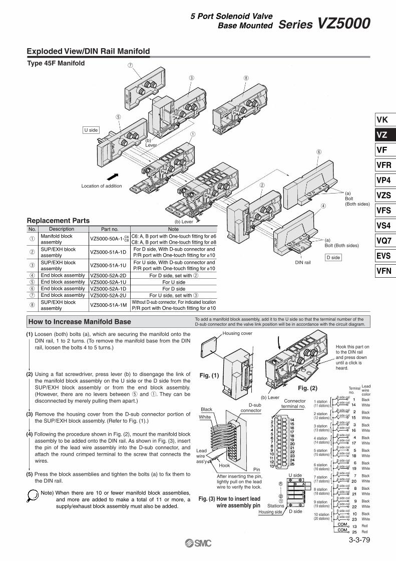
(1) Loosen (both) bolts (a), which are securing the manifold onto the DIN rail, 1 to 2 turns. (To remove the manifold base from the DIN rail, loosen the bolts 4 to 5 turns.)
(2) Using a flat screwdriver, press lever (b) to disengage the link of the manifold block assembly on the U side or the D side from the SUP/EXH block assembly or from the end block assembly. (However, there are no levers between t and q. They can be disconnected by merely pulling them apart.)
(3) Remove the housing cover from the D-sub connector portion of the SUP/EXH block assembly. (Refer to Fig. (1).)
(4) Following the procedure shown in Fig. (2), mount the manifold block assembly to be added onto the DIN rail. As shown in Fig. (3), insert the pin of the lead wire assembly into the D-sub connector, and attach the round crimped terminal to the screw that connects the wires.
(5) Press the block assemblies and tighten the bolts (a) to fix them to
the DIN rail.
Note) When there are 10 or fewer manifold block assemblies, and more are added to make a total of 11 or more, a supply/exhaust block assembly must also be added.
Replacement PartsNo.
w
w
e
e
q
q
Description
VZ5000-51A-1D
VZ5000-51A-1U
Part no.
VZ5000-50A-1-
r
r
VZ5000-52A-2D
For D side, With D-sub connector andP/R port with One-touch fitting for ø10
For U side, With D-sub connector andP/R port with One-touch fitting for ø10
Note
SUP/EXH block assembly
Manifold block assembly
SUP/EXH block assemblyEnd block assembly
t
t
VZ5000-52A-1U For U sideEnd block assemblyy
y
VZ5000-52A-1D For D sideEnd block assemblyu
u
VZ5000-52A-2UEnd block assembly
i
i
VZ5000-51A-1MWithout D-sub connector, For indicated locationP/R port with One-touch fitting for ø10
SUP/EXH block assembly
C6C8
Exploded View/DIN Rail Manifold
How to Increase Manifold Base
Type 45F Manifold
To add a manifold block assembly, add it to the U side so that the terminal number of the D-sub connector and the valve link position will be in accordance with the circuit diagram.
For D side, set with w
C6: A, B port with One-touch fitting for ø6C8: A, B port with One-touch fitting for ø8
For U side, set with e
Fig. (3) How to insert lead wire assembly pin
(a) Bolt(Both sides)
(a) Bolt (Both sides)
DIN rail
Location of addition
BlackWhite
BlackWhite
BlackWhite
BlackWhite
BlackWhite
BlackWhite
BlackWhite
BlackWhite
BlackWhite
BlackWhite
Red
Red
Leadwire color
Terminalno.
B side coil
A side coil
B side coil
A side coil
B side coil
A side coil
B side coil
A side coil
B side coil
A side coil
B side coil
A side coil
B side coil
A side coil
B side coil
A side coil
B side coil
A side coil
B side coil
A side coil
Hook this part onto the DIN rail and press down until a click is heard.
1 station(11 stations)
2 station(12 stations)
3 station(13 stations)
4 station(14 stations)
5 station(15 stations)
6 station(16 stations)
7 station(17 stations)
8 station(18 stations)
9 station(19 stations)
10 station(20 stations)
Housing cover
Fig. (1)
Fig. (2)
(b) Lever
Black
White
HookPin
Leadwireass'y
D-subconnector
Connectorterminal no.
U side
D side
After inserting the pin,lightly pull on the leadwire to verify the lock.
Housing sideStations
(b)Lever
(b) Lever
U side
D side
3-3-79
Series VZ50005 Port Solenoid Valve
Base Mounted
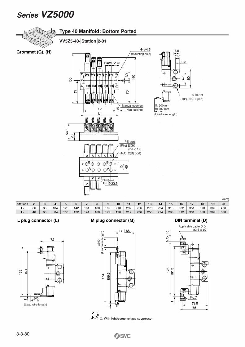
�: With light /surge voltage suppressor
Grommet (G), (H)
(mm)
L plug connector (L) DIN terminal (D)M plug connector (M)
Stations 2 36646
8565
4104
84
5123103
6142122
7161141
8180160
9199179
10218198
11237217
12256236
13275255
14294274
15313293
16332312
17351331
18370350
19389369
20408388
L1
L2
Type 40 Manifold: Bottom Ported
VV5Z5-40- Station 2-01
Manual override(Non-locking)
6-Rc 1/4(1(P), 3/5(R) port)
(Pitch)
(Mounting hole)
≅300
(Lead wire length)
≅300
(Lea
d w
ire le
ngth
)
MA
X. 1
0
Applicable cable O.D.ø3.5 to ø7
PE port(Pilot EXH)
2n-Rc 1/8(4(A), 2(B) port)
G: 300 mmH: 600 mm
(Lead wire length)
Series VZ5000
3-3-80
VK
VZ
VF
VFR
VP4
VZS
VFS
VS4
VQ7
EVS
VFN
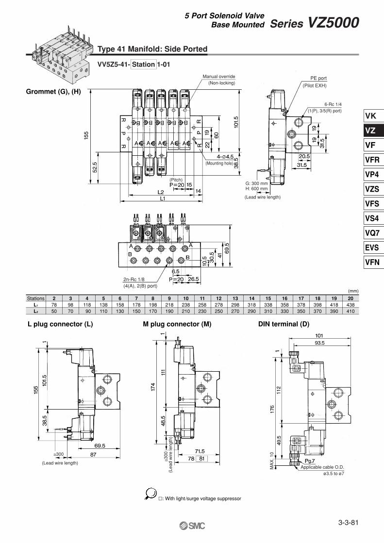
Type 41 Manifold: Side Ported
�: With light /surge voltage suppressor
Grommet (G), (H)
(mm)
L plug connector (L) DIN terminal (D)M plug connector (M)
Stations 2 37850
9870
411890
5138110
6158130
7178150
8198170
9218190
10238210
11258230
12278250
13298270
14318290
15338310
16358330
17378350
18398370
19418390
20438410
L1
L2
VV5Z5-41- Station 1-01
Manual override(Non-locking)
6-Rc 1/4(1(P), 3/5(R) port)
(Pitch)
(Mounting hole)
≅300
(Lead wire length)
≅300
(Lea
d w
ire le
ngth
)
MA
X. 1
0
PE port
(Pilot EXH)
2n-Rc 1/8(4(A), 2(B) port)
G: 300 mmH: 600 mm
(Lead wire length)
Applicable cable O.D.ø3.5 to ø7
3-3-81
Series VZ50005 Port Solenoid Valve
Base Mounted
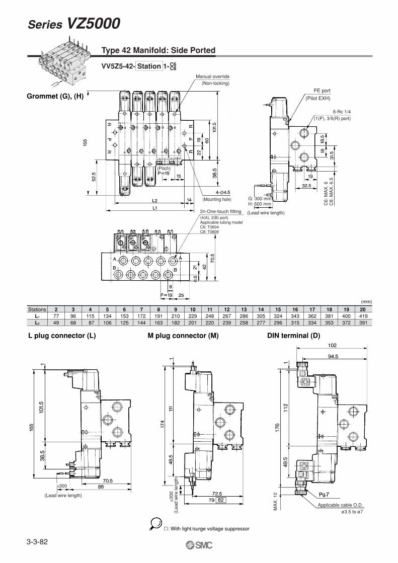
�: With light /surge voltage suppressor
Grommet (G), (H)
(mm)
L plug connector (L) DIN terminal (D)M plug connector (M)