TRNSYS – Type 336 Manual 5–1 5. Type 336 Air handling unit with sensible and latent heat recovery with economizer 5.1. General description An air handling unit (AHU) is used to calculate the energy consumption of heating and/or cooling (outside) air to a certain setpoint. This type is considered to be mainly used in combination with type 56 (multizone building) for ventilation. By specifying different parameters the AHU can act as a (air) heat recovery unit only, or as a full HVAC component where the air is heated, cooled, humidified and dehumidified. In addition, a frost protection temperature setting at the heat recovery device and a bypass mode can be specified. The following modes are available: Sensible and/or latent heat recovery Frost protection (Re-)heating and (re-)cooling Humidification and/or dehumidification Bypass of heat recovery Adiabatic cooling of exhaust air by humidification Recirculation Economizer 5.2. Nomenclature Aref m² Reference area for calculation of specific outputs c p,Air kJ/kgK Specific heat capacity of air at approx. inlet/outlet air temp. conditions ModeHTCL - Mode for heating and/or cooling humidification/dehumidification ModeFP - Mode for frost protection ModeBP - Mode for bypass RA m kg/h Return air mass flowrate OA m kg/h Outdoor air mass flowrate SA m kg/h Supply air mass flowrate EA m kg/h Exhaust air mass flowrate AD cl, Q kJ/h Possible adiabatic cooling power by humidification of the return air DEHUM cl, Q kJ/h Required cooling power demand for dehumidification CC cl, Q kJ/h Required cooling power by cooling coil DEHUM HT, Q kJ/h Required heat after dehumidification to reach the desired supply air temperature PHC HT, Q kJ/h Required heating power by pre-heating coil
Transcript
TRNSYS – Type 336 Manual
5–1
5. Type 336 Air handling unit with sensible and latent heat recovery with economizer
5.1. General description
An air handling unit (AHU) is used to calculate the energy consumption of heating and/or cooling (outside) air to a certain setpoint. This type is considered to be mainly used in combination with type 56 (multizone building) for ventilation. By specifying different parameters the AHU can act as a (air) heat recovery unit only, or as a full HVAC component where the air is heated, cooled, humidified and dehumidified. In addition, a frost protection temperature setting at the heat recovery device and a bypass mode can be specified. The following modes are available:
Sensible and/or latent heat recovery
Frost protection
(Re-)heating and (re-)cooling
Humidification and/or dehumidification
Bypass of heat recovery
Adiabatic cooling of exhaust air by humidification
Recirculation
Economizer
5.2. Nomenclature
Aref m² Reference area for calculation of specific outputs
cp,Air kJ/kgK Specific heat capacity of air at approx. inlet/outlet air temp. conditions
ModeHTCL - Mode for heating and/or cooling humidification/dehumidification
ModeFP - Mode for frost protection
ModeBP - Mode for bypass
RAm kg/h Return air mass flowrate
OAm kg/h Outdoor air mass flowrate
SAm kg/h Supply air mass flowrate
EAm kg/h Exhaust air mass flowrate
ADcl,Q kJ/h Possible adiabatic cooling power by humidification of the return air
DEHUMcl,Q kJ/h Required cooling power demand for dehumidification
CCcl,Q kJ/h Required cooling power by cooling coil
DEHUMHT,Q kJ/h Required heat after dehumidification to reach the desired supply air temperature
PHCHT,Q kJ/h Required heating power by pre-heating coil
TRNSYS – Type 336 Manual
5–2
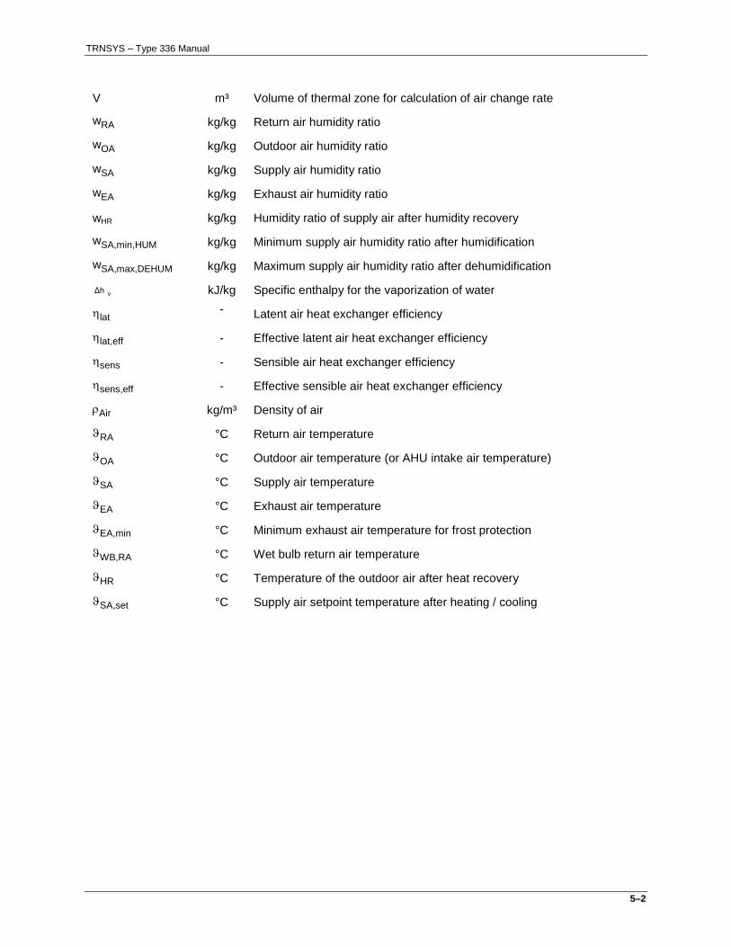
V m³ Volume of thermal zone for calculation of air change rate
wRA kg/kg Return air humidity ratio
wOA kg/kg Outdoor air humidity ratio
wSA kg/kg Supply air humidity ratio
wEA kg/kg Exhaust air humidity ratio
wHR kg/kg Humidity ratio of supply air after humidity recovery
wSA,min,HUM kg/kg Minimum supply air humidity ratio after humidification
wSA,max,DEHUM kg/kg Maximum supply air humidity ratio after dehumidification
vΔh kJ/kg Specific enthalpy for the vaporization of water
lat - Latent air heat exchanger efficiency
lat,eff - Effective latent air heat exchanger efficiency
sens - Sensible air heat exchanger efficiency
sens,eff - Effective sensible air heat exchanger efficiency
Air kg/m³ Density of air
RA °C Return air temperature
OA °C Outdoor air temperature (or AHU intake air temperature)
SA °C Supply air temperature
EA °C Exhaust air temperature
EA,min °C Minimum exhaust air temperature for frost protection
WB,RA °C Wet bulb return air temperature
HR °C Temperature of the outdoor air after heat recovery
SA,set °C Supply air setpoint temperature after heating / cooling
TRNSYS – Type 336 Manual
5–3
5.3. Mathematical Description
The air handling unit offers many different operating modes. A description of the different modes, their fundamental equations, and their associated variables are given in the following text. A schematic sketch of the AHU is shown in Figure 1 and 2.
Figure 1: AHU Schematic – Winter
Figure 2: AHU Schematic – Summer
The amount of outdoor air which is used for calculation of the energy demand for air treatment is based on the mass flow of supply air (specified by Input 14) and re-circulation air. If no recirculation air is used (parameter 14 = 0) then mass flow of supply air is equal to mass flow of outdoor air.
Fa
n
Hu
mid
ifie
r
Pre
-he
ati
ng
co
il
He
ati
ng
co
il
Co
oli
ng
co
il
O u td o o r a ir
E x h a u s t a ir
E x tra c t a ir
S u p p ly a ir
By
pa
ss
He
at
Re
co
ve
ry
re-c
irc
air
_ R A
w _ R A
_ O A
w _ O A
( _ O A )
m _ O A
_ E A
_ E A
m _ E A
_ S A
w _ S A
m _ S A
_ S A
_ H R
(w _ R A )
_ R A
Fa
n
Hu
mid
ifie
r
Pre
-he
ati
ng
co
il
He
ati
ng
co
il
Co
oli
ng
co
il
He
at
Re
co
ve
ry
O u td o o r a ir
E x h a u s t a ir
E x tra c t a ir
S u p p ly a ir
re-c
irc
air
_ R A
w _ R A
_ O A
w _ O A
( _ O A )
m _ O A
_ E A
_ E A
m _ E A
_ S A
w _ S A
m _ S A
_ S A
_ H R
(w _ R A )
_ R A
Ad
iab
ati
c c
oo
lin
g
hu
mid
ifie
r
TRNSYS – Type 336 Manual
5–4
The definition of outdoor air is used as a general description but the user can specify any inlet conditions to the unit. These inputs are used for calculation of the energy demand for air treatment.
5.4. Sensible Heat Recovery
The equations describe how the efficiency of the heat recovery is calculated. Due to the fact that the exhaust air flow rate is not necessarily identical to the delivery air flow rate, the specified sensible and latent efficiency is replaced by an effective efficiency. This effective efficiency is calculated related to the mass flow rate relation between both air streams.
sens
OA
RA
effsens,η
m
mη
(5-1)
lat
OA
SA
efflat,η
m
mη
(5-2)
These efficiencies are characteristic for both the heat exchange and the humidity recovery behavior between both air streams. Resulting from the definition of the effective sensible efficiency the temperature of the delivery air after the heat exchanger is calculated by the following equation:
OAOARAeffsens,HR
η (5-3)
5.5. Frost protection
In order to avoid icing of the heat exchanger from the AHU it can be important to protect the heat exchanger from very low temperatures. For this case, the type offers the function of frost protection to
define a minimum exhaust air temperature by EA,min. This leads to the calculation of the supply air as in eq. (5-4).
minEA, = minimum exhaust air temperature of the AHU output for frost protection
OAminEA,RAOARAeffsens,HR
,ηMin (5-4)
5.6. Humidity recovery
The type offers the possibility to use humidity recovery from the return air to the supply air. The integrated simple model requires only the humidity recovery efficiency as an input. The absolute humidity of the supply air stream after humidity recovery is calculated as:
OAOARAefflat,HRHUM,
wwwηw (5-5)
TRNSYS – Type 336 Manual
5–5
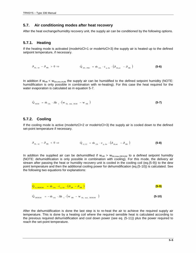
5.7. Air conditioning modes after heat recovery
After the heat exchange/humidity recovery unit, the supply air can be conditioned by the following options.
5.7.1. Heating
If the heating mode is activated (modeHzCl=1 or modeHzCl=3) the supply air is heated up to the defined setpoint temperature, if necessary.
0HRsetSA,
HRSA,setAirp,OAPHCHT,
cmQ (5-6)
In addition if wHR < wSA,min,HUM the supply air can be humidified to the defined setpoint humidity (NOTE: humidification is only possible in combination with re-heating). For this case the heat required for the water evaporation is calculated as in equation 5-7.
HRHUMmin,SA,vOAHUM
wwΔhmQ (5-7)
5.7.2. Cooling
If the cooling mode is active (modeHzCl=2 or modeHzCl=3) the supply air is cooled down to the defined set-point temperature if necessary.
0HRsetSA,
HRSA,setAirp,OACCcl,
cmQ (5-8)
In addition the supplied air can be dehumidified if wHR > wSA,max,DEHUM to a defined setpoint humidity (NOTE: dehumidification is only possible in combination with cooling). For this mode, the delivery air stream after passing the heat or humidity recovery unit is cooled in the cooling coil (eq.(5-9)) to the dew point temperature and then the additional cooling power for dehumidification (eq.(5-10)) is calculated. See the following two equations for explanations:
HRDPAirp,OADEHUMcl,
cmQ (5-9)
DEHUMmax,SA,HRvOADEHUM
wwΔhmQ (5-10)
After the dehumidification is done the last step is to re-heat the air to achieve the required supply air temperature. This is done by a heating coil where the required sensible heat is calculated according to the previous required dehumidification and cool down power (see eq. (5-11)) plus the power required to reach the set-point temperature.
TRNSYS – Type 336 Manual
5–6
HRsetSA,Airp,OADEHUMcl,DEHUMHT,
cmQQ (5-11)
5.8. Bypass
For avoiding overheating/overcooling of the supply air by the heat exchanger, a bypass mode is integrated in the type. If the bypass mode is activated (modeBP=1) only the mass flow of the return air required for reaching the set-point supply air temperature flows through the heat recovery unit; the rest is sent through the bypass.
5.9. Special Mode: Adiabatic cooling of the return air
Adiabatic cooling can be activated by a hidden switch, setting latent efficiency < 0. The return air is cooled down by humidification to the minimum wet bulb temperature before entering the heat recovery unit.
Followed by this WRG can be reduced to the required supply air temperature to the zone. !!Note: By using this mode it is not possible to use humidity recovery and bypass mode.!! The calculation works as follows:
1) The new required return air temperature is calculated according to setSA,HR
by recalculating from
the effective sensible efficiency
RAWB,OAeffsens,OAsetSA,NEWRA,
,/ηMAX (5-12)
2) From this the adiabatic cooling power is calculated depending on the WRG change before and after
the use of adiabatic cooling.
OADHR,WADAirp,SAADcl,
cmQ (5-13)
WAD = with adiabatic cooling
OAD = without adiabatic cooling
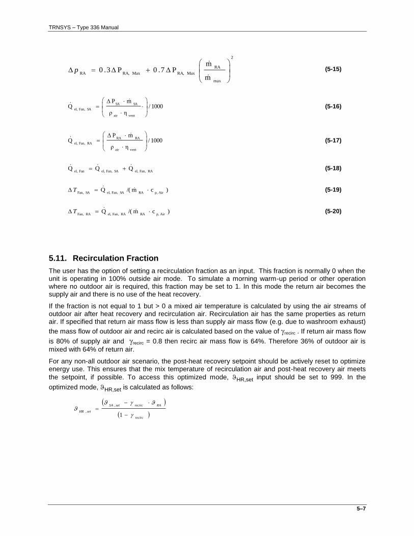
5.10. Fan Power
The total power of both the supply and exhaust fans is calculated based on the actual supply and return air flowrates,
SAm and
RAm , and the maximum supply fan flowrate, pressure drops, and fan efficiency
given as parameters. Note that the impact of heat generated by the fan and motor on either airstream is not considered; this calculation is for determination of electrical power only. The total fan power is calculated as:
2
max
SA
MaxSA,MaxSA,SA
m
mP7.0P3.0
p (5-14)
TRNSYS – Type 336 Manual
5–7
2
max
RA
MaxRA,MaxRA,RA
m
mP7.0P3.0
p
(5-15)
1000/ηρ
mPQ
ventair
SASA
SAFan,el,
(5-16)
1000/ηρ
mPQ
ventair
RARA
RAFan,el,
(5-17)
RAFan,el,SAFan,el,Fanel,QQQ (5-18)
)c m/(QAirp,RASAFan,el,SAFan,
T (5-19)
)c m/(QAirp,RARAFan,el,RAFan,
T (5-20)
5.11. Recirculation Fraction
The user has the option of setting a recirculation fraction as an input. This fraction is normally 0 when the unit is operating in 100% outside air mode. To simulate a morning warm-up period or other operation where no outdoor air is required, this fraction may be set to 1. In this mode the return air becomes the supply air and there is no use of the heat recovery.
If the fraction is not equal to 1 but > 0 a mixed air temperature is calculated by using the air streams of outdoor air after heat recovery and recirculation air. Recirculation air has the same properties as return air. If specified that return air mass flow is less than supply air mass flow (e.g. due to washroom exhaust)
the mass flow of outdoor air and recirc air is calculated based on the value of recirc . If return air mass flow
is 80% of supply air and recirc = 0.8 then recirc air mass flow is 64%. Therefore 36% of outdoor air is
mixed with 64% of return air.
For any non-all outdoor air scenario, the post-heat recovery setpoint should be actively reset to optimize energy use. This ensures that the mix temperature of recirculation air and post-heat recovery air meets
the setpoint, if possible. To access this optimized mode, HR,set input should be set to 999. In the
optimized mode, HR,set is calculated as follows:
recirc
RArecircsetSA
setHR
1
,
,
TRNSYS – Type 336 Manual
5–8
Figure 3: Schematic of calculation of re-circulation air
5.12. Economizer
The user has the option of specifying whether the air handling unit has an air-side economizer function. This mode will ignore the user-defined recirculation fraction, and set the mixed air ratio based on the economizer control. In economizer mode, the recirculation fraction will decrease (increase outdoor air supply) when outside conditions permit free cooling. If outdoor conditions are ideal for cooling, the AHU will use 100% outside air. When outside air requires heating or cooling before being supplied to the building, the recirculation fraction will be set to use a minimum of outside air.
Figure 4: Air mixing in economizer mode
Note: to maintain user-control of the recirculation fraction, the economizer mode should be disabled (set to 0).
_ H R
(w _ R A )
_ R A
_ m ix
(w _ m ix )
_ m ix
_ R A
w _ R A
re c irc
= 8 0 %
8 0 %
1 0 0 %
1 0 0 % - 6 4 % = 3 6 %
3 6 % + 6 4 % = 1 0 0 %
TRNSYS – Type 336 Manual
5–9
The economizer has several modes of high-limit shutoff control, corresponding to the control settings in ASHRAE 90.1-2010:
Economizer Mode Control Type Economizer off when
0 Off Off (user control of recirc fraction)
1 Fixed dry bulb limitOA,OA
2 Differential dry bulb RAOA
3 Fixed enthalpy limitOA,OA
hh
4 Differential enthalpy RAOA
hh
5 Morning Warmup OA set to 0%
The economizer settings are determined in three steps (see table above). First, if an economizer mode is enabled (EconMode is above 0 and below 5) and the AHU is in a cooling mode (supply setpoint is below the return temperature), a theoretical ideal recirculation fraction is calculated:
RAOArecirc
RAOA
OARARA
OAsetSASA
recirc
m
m
|
|
,
,0
,
Second, recirc is fixed between minimum and maximum limits:
max,0
OArecirc
Where,
RA
OASA
OA
m
mm
min,
max,
Finally, the economizer control type is applied. recirc is reset to OA,max if the control “off” condition is
0 = No heating/cooling and no humidification/dehumidification
Heat recovery only (if Sens > 0) 1 = Heating and humidification; no cooling/dehumidification 2 = Cooling and dehumidification; no heating/humidification 3 = Heating, cooling, humidification and dehumidification
2 modeFP Frost protection Yes/No -
0 = no frost protection 1 = minimum exhaust air temperature is user-defined
3 modeBP Bypass Yes/No -
0 = no bypass 1 = bypass temperature controlled (to meet set point) 2 = bypass enthalpy controlled (energy optimized)
4 Air Density of Air kg/m3
5 cp,Air Spec. heat capacity of Air kJ/(kg*K)
6 hv Enthalpy of vaporization of water kJ/kg
7 Aref Reference area for specific power calculation m2
8 V Zone volume for air change rate calculation m3
9 PSA,max Maximum supply side pressure drop Pa
10 PRA,max Maximum return side pressure drop Pa
11 vent Overall efficiency of fan and motor -
12 Maxm Maximum fan mass flowrate kg/h
5.14. Description of Inputs
The following input values are used for calculating the thermal performance of the AHU:
Input no Symbol Description Unit
1 OA Outdoor air temperature °C
2 wOA Absolute water content of outdoor air kg/kg
3 Not used any more
4 RA Return air temperature (to AHU from zone) °C
5 wRA Absolute water content of return air (to AHU from zone) kg/kg
6 RAm Mass flow rate of return air (to AHU from zone) kg/h
7 Sens Sensible efficiency of heat recovery -
8 Lat Latent efficiency of humidity recovery -
Two different AHU operating modes can be set by Lat: =0 => no humidity recovery between exhaust and delivery air stream >0 => Humidity recovery enabled
9 EA,min Exhaust air, minimum temperature for frost protection °C
10 HR,set Supply air temperature setpoint after heat recovery (set to 999 to allow optimization of setpoint for recirculation systems)
°C
11 SA,set Supply air temperature setpoint after the AHU (from AHU to zone) °C
12 wSA,min,hum Absolute water content of the supply air after humidification (min setp.) kg/kg
13 wSA,max,dehum Absolute water content of the supply air after dehum.(max. setpoint) kg/kg
14 SAm Mass flow rate of supply air = sum of mass flow of OA + re-circ air kg/h
15 recirc Fraction of return air to be recirculated
16 modeEcon 0 = No economizer 1 = Economizer with fixed dry bulb high-limit control 2 = Economizer with differential dry bulb high-limit control 3 = Economizer with fixed enthalpy high-limit control 4 = Economizer with differential enthalpy high-limit control 5 = Morning warmup (recirculation fraction set for 100% recirculation)
-
17 minOA,m Minimum outdoor airflow kg/h
18 ECO,set Fixed dry bulb control setpoint (for modeEcon = 1) °C
TRNSYS – Type 336 Manual
5–2
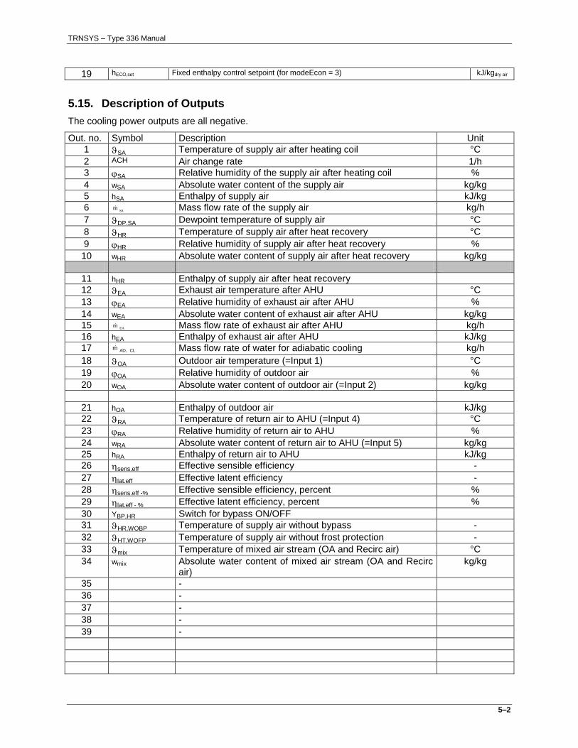
19 hECO,set Fixed enthalpy control setpoint (for modeEcon = 3) kJ/kgdry air
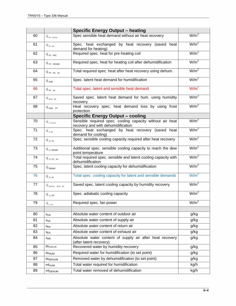
5.15. Description of Outputs
The cooling power outputs are all negative.
Out. no. Symbol Description Unit
1 SA Temperature of supply air after heating coil °C
2 ACH Air change rate 1/h
3 SA Relative humidity of the supply air after heating coil %
4 wSA Absolute water content of the supply air kg/kg
5 hSA Enthalpy of supply air kJ/kg
6 SAm Mass flow rate of the supply air kg/h
7 DP,SA Dewpoint temperature of supply air °C
8 HR Temperature of supply air after heat recovery °C
9 HR Relative humidity of supply air after heat recovery %
10 wHR Absolute water content of supply air after heat recovery kg/kg
11 hHR Enthalpy of supply air after heat recovery
12 EA Exhaust air temperature after AHU °C
13 EA Relative humidity of exhaust air after AHU %
14 wEA Absolute water content of exhaust air after AHU kg/kg
15 EAm Mass flow rate of exhaust air after AHU kg/h
16 hEA Enthalpy of exhaust air after AHU kJ/kg
17 CLAD,m Mass flow rate of water for adiabatic cooling kg/h
18 OA Outdoor air temperature (=Input 1) °C
19 OA Relative humidity of outdoor air %
20 wOA Absolute water content of outdoor air (=Input 2) kg/kg
21 hOA Enthalpy of outdoor air kJ/kg
22 RA Temperature of return air to AHU (=Input 4) °C
23 RA Relative humidity of return air to AHU %
24 wRA Absolute water content of return air to AHU (=Input 5) kg/kg