5 Way Strat Switch Explained You’ve played em’ and you’ve heard em’ but have you ever wondered how exactly a 5- way Strat switch works? We’ve put together an in -depth 3-part series that pulls back the pickguard on one of the most common switches you’ll come across. In Part 1 we take a close look at how a 5 -way Strat switch works. In Part 2 we build off this knowledge and look at the most common way to wire a Strat. Finally, in Part 3 we’ll show you some very simple modifications that you can do to customize your guitar.
Transcript
5 Way Strat Switch Explained
You’ve played em’ and you’ve heard em’ but have you ever wondered how exactly a 5-way Strat switch works? We’ve put together an in-depth 3-part series that pulls back the pickguard on one of the most common switches you’ll come across. In Part 1 we take a close look at how a 5-way Strat switch works. In Part 2 we build off this knowledge and look at the most common way to wire a Strat. Finally, in Part 3 we’ll show you some very simple modifications that you can do to customize your guitar.
A dash of history
5 way Strat switch has a few more indents.
The 5-way Strat switch is the most common switch you’ll find in Stratocaster guitars. The original Stratocaster had a 3-way switch (same as a Tele) to select one of three pickups. But over time players noticed an interesting sound when switching from one pickup to the next. Guitarists found they could turn on more than one pickup at a time to get the “in-between” sounds. To achieve this, they had to do a little MacGyver action by putting match sticks or paper to keep the switch in just the right place. Finally, in 1977 Fender made the 5-way Strat switch a standard feature in their guitars. Both 3-way and 5-way switches are wired the same. The only difference is the 5-way has a few more indents (Fig 4).
What the heck is a 5-way Switch?
On a basic level, switches are connectors. They connect one or more terminals together. The 5-way Strat switch uses a blade to connect or “wipe” across the terminals (Fig. 1A). Looking at Fig 1B, you’ll notice there is a common terminal that is always connected. We’ll get into the common terminal a bit more later. Another thing to note is there are two sides to the switch—Pole A and Pole B (Fig. 2). Both sides work the same way. The only difference is the physical distance between terminals, and the numbers work in the opposite direction. That is why the commons are on the opposite ends of the switch (vertically speaking).
Because both sides work the same way, lets take a closer look at Pole B to see exactly what’s going on (Pole A is hard to see because of the cover). There are two parts to the wiper— The common (marked in red Fig. 1A) and wide connector (marked in yellow Fig. 1A). In Fig. 1A, you can see terminal B2 and B0 are connected. The lower half of the wiper (in red) is always connected to the “common” terminal. Terminal A0 is common on Pole A side and terminal B0 is common on Pole B side.
The wide part of the wiper (in yellow in Fig. 1A) connects A1-A3 and B1-B3 terminals to their respective common terminal. As you may guess, this wider part of the wiper is just wide enough to connect two terminals at the same time (see position 2 and 4 Fig. 1B), but is also narrow enough to connect only one terminal to the common (see position 1,3, 5 Fig. 1B).
In Fig. 1B, notice how all the positions connect to B0 (common). The common is always “on” and will never disconnect from the wiper. This makes a perfect place to connect our volume pot which would be connected to our output jack. This allows us to control any “live” or “hot” pickup or pickups that have been selected via the switch. Now lets take a look at the top side of the switch (Fig 3A-3E). This is a good birds eye view of both poles and each position. Remember, these two poles work independently
meaning they are not connected to each other. You’ll see in Part 2 how we’ll connect both sides of the poles.
Two Side
POSITION 1
Pole A: A1 and A0 are connected | Pole B: B1 and B0 are connected
POSITION 2
Pole A: A1, A2, and A0 are connected | Pole B: B1, B2, and B0 are connected
POSITION 3
Pole A: A2 and A0 are connected | Pole B: B2 and B0 are connected
POSITION 4
Pole A: A3, A2, and A0 are connected | Pole B: B3, B2, and B0 are connected
POSITION 5
Pole A: 5 = A3 is connected to A0 | Pole B: B3 is connected to B0
Connecting the 5-Way Strat Switch
If you remember from Part 1, the anatomy of a 5 way Strat switch, we have two sides: Pole A and Pole B (Fig 1). First, we have to connect both sides of the switch by adding a “jumper” from terminal A0 to B0 (Fig 2).
Remember A0 and B0 are the common terminals. This allows us to use both sides of the switch for different functions. Once we have both sides connected via the jumper, we can add the pickup hot lead wires to Pole A
side of the switch. In a standard Stratocaster wiring configuration, the bridge pickup goes to A1, middle to A2, and neck to A3 (Fig 3). Next, we will attach the Tone 1 (closest to your volume pot) lead wire to B3 and tone 2 to B2. Finally, we’ll attach our volume lead wire to common B0.
All 5 POSITIONS
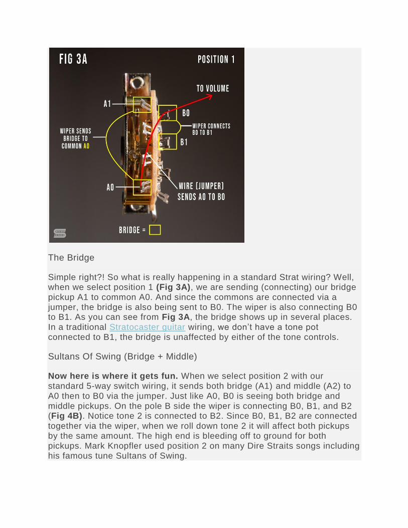
The Bridge
Simple right?! So what is really happening in a standard Strat wiring? Well, when we select position 1 (Fig 3A), we are sending (connecting) our bridge pickup A1 to common A0. And since the commons are connected via a jumper, the bridge is also being sent to B0. The wiper is also connecting B0 to B1. As you can see from Fig 3A, the bridge shows up in several places. In a traditional Stratocaster guitar wiring, we don’t have a tone pot connected to B1, the bridge is unaffected by either of the tone controls.
Sultans Of Swing (Bridge + Middle)
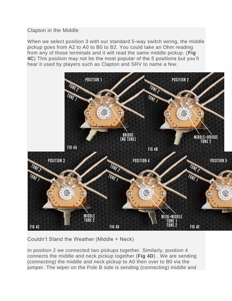
Now here is where it gets fun. When we select position 2 with our standard 5-way switch wiring, it sends both bridge (A1) and middle (A2) to A0 then to B0 via the jumper. Just like A0, B0 is seeing both bridge and middle pickups. On the pole B side the wiper is connecting B0, B1, and B2 (Fig 4B). Notice tone 2 is connected to B2. Since B0, B1, B2 are connected together via the wiper, when we roll down tone 2 it will affect both pickups by the same amount. The high end is bleeding off to ground for both pickups. Mark Knopfler used position 2 on many Dire Straits songs including his famous tune Sultans of Swing.
When we select position 3 with our standard 5-way switch wiring, the middle pickup goes from A2 to A0 to B0 to B2. You could take an Ohm reading from any of those terminals and it will read the same middle pickup. (Fig 4C) This position may not be the most popular of the 5 positions but you’ll hear it used by players such as Clapton and SRV to name a few.
Couldn’t Stand the Weather (Middle + Neck)
In position 2 we connected two pickups together. Similarly, position 4 connects the middle and neck pickup together (Fig 4D) . We are sending (connecting) the middle and neck pickup to A0 then over to B0 via the jumper. The wiper on the Pole B side is sending (connecting) middle and
neck to two terminals B2 and B3. Therefore, B2 and B3 are also connected to tone 1 and tone 2 respectively.
Since the middle and neck are both connected to tone 1 and tone 2 we can use either one. The tone pot rolled down the most will take precedence over the other. So, if you have tone 1 rolled all the way down but tone 2 all the way up, you will hear only the effect of tone 1 since it’s bleeding off more high end of the two pots to ground. Frequencies are set by the capacitor and the amount is set by where the pot is positioned.
Position 4 is one of the most used Stat positions. You’ll hear players from SRV, Hendrix, to John Mayer use this this juicy position both live and in the studio.
The Wind Cries Mary (Neck)
Last but not least, we have position 5 (Fig 4E). We all love a good neck tone right?! Using the standard Strat wiring in this position, the neck pickup goes from A3 to A0 to B0 to B3. Tone 2 is connected to B3 which allows us to set our desired tone level to the neck pickup. Position 5 is another common position among blues, rock, and jazz players.
More than 1-way!
Now, one thing may have crossed your mind. Why not hook up the tone lead wires to the Pole A side terminals A2 and A3? Wouldn’t that essentially do the same thing without having to use a jumper? Good question young padawan. You are absolutely right! The switch would function the same if you kept the jumper from A0 to B0 or move your volume lead wire to A0.
So why does Fender wire Strats this way? We suspect the reasons the standard Strat wiring originally utilized the switch this way are twofold: firstly, Fender already had lots and lots of three-way, two-pole switches in stock because they needed them for the Telecaster; and secondly, it’s easier to solder one wire to a contact than it is to solder two. If they already had those switches, why not make it easier to solder?
The good news is there’s a good reason to leave the jumper connected to A0 and B0. This jumper will allow us to mod our switch to better suit our specific playing styles.