34
500 kV AC Underground Transmission Evaluation Fred Ritter, P.Eng. Technical Lead - Engineering
500 kV AC Underground Transmission Evaluation
Fred Ritter, P.Eng.
Technical Lead - Engineering
2
Presentation Outline
• Overview of Study and Objectives
• Key Participants of Study
• Technical Aspects and Challenges
• World EHV cable experience
• Cost Comparisons
• CCI report Conclusions/Recommendations
• Next Steps
3
Study Objectives
• Examine the technical feasibility of placing a portion of the Heartland 500 kV circuits underground in order to mitigate siting issues
• Enhance knowledge of underground transmission given the considerable opposition to overhead transmission siting from landowners

4
Edmonton Area Transmission System Development
Ellerslie
Genesee
Keephills
Heartland
Line Voltages240 kV
500 kV
To Southern Alberta
East Side HVDC
Terminal
Fort McMurray
East Option
West Option

5
Losses
Rating Capability
ReliabilityAvailability
MaintainabilityQuantify
Practicability
Risks
Capital Costs
Life Cycle
Costing
Technical Feasibility
Study
500 kVUnderground
Cables
Feasibility Study Focus Areas
6
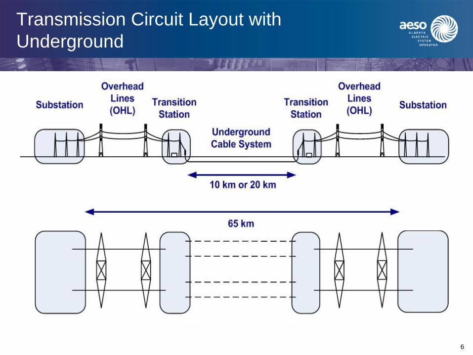
Transmission Circuit Layout with Underground
7
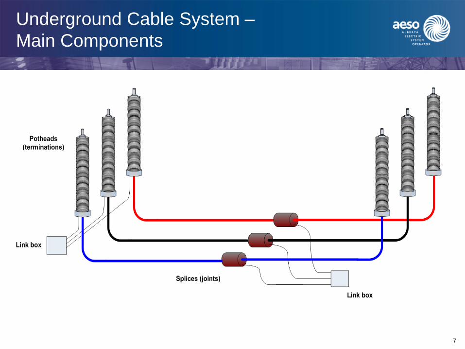
Underground Cable System –Main Components
8
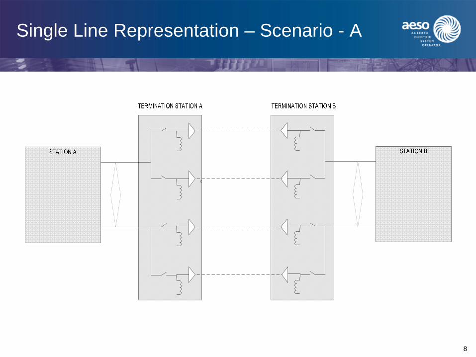
Single Line Representation – Scenario - A
9
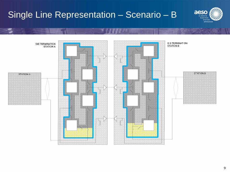
Single Line Representation – Scenario – B
10
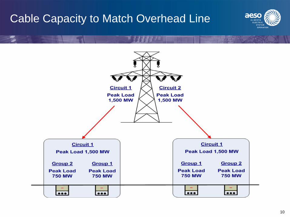
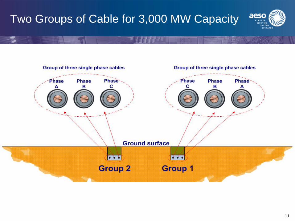
Cable Capacity to Match Overhead Line
11
Two Groups of Cable for 3,000 MW Capacity
12
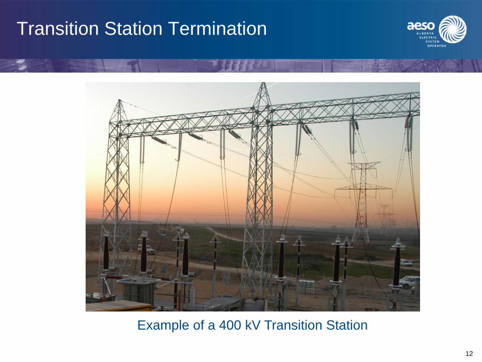
Transition Station Termination
Example of a 400 kV Transition Station
13
Study Participants
• Cable Consulting International (CCI) of the UK was contracted by the AESO to carry out the study
• Teshmont Consulting contracted by the AESO to study reactive power requirements, system losses, and reliability
• AltaLink and EPCOR provided certain inputs including such items as constructability, operating/maintenance issues, transport limitations, cost estimates for civil works, transition station layouts and costs, and general routing data
14
Technical Aspects of Study
• 500 kV AC underground cable required to carry 3,000 MVA on each circuit
• Nominal voltage – 500 kV; maximum 550 kV
• 1,550 kV BIL
• Need for reactors
• Burial options; trench or tunnel
• Cold temperature considerations
• Number of cables per phase
• Reliability/Availability
• Maintenance and operating considerations
• Maximum lengths

15
EHV (XLPE) Underground Cable Around the World
North America- 240 kV and 345 kV
Europe- 400 kV
Japan-500 kV
China-500 kV
Middle East – 400 kV
16
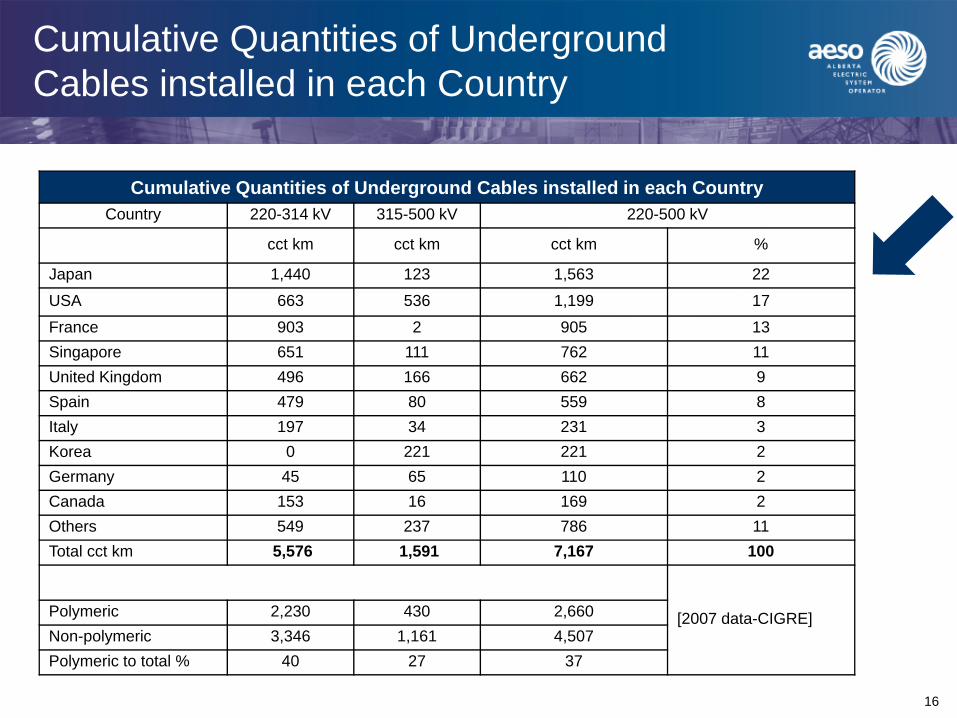
Cumulative Quantities of Underground Cables installed in each Country
Cumulative Quantities of Underground Cables installed in each Country Country 220-314 kV 315-500 kV 220-500 kV
cct km cct km cct km %
Japan 1,440 123 1,563 22USA 663 536 1,199 17France 903 2 905 13Singapore 651 111 762 11United Kingdom 496 166 662 9Spain 479 80 559 8Italy 197 34 231 3Korea 0 221 221 2Germany 45 65 110 2Canada 153 16 169 2Others 549 237 786 11Total cct km 5,576 1,591 7,167 100
[2007 data-CIGRE]Polymeric 2,230 430 2,660Non-polymeric 3,346 1,161 4,507Polymeric to total % 40 27 37

17
Shinkeiyo-Toyosu 500 kV Line
• Connecting Shin-Toyosu S/S and Shin-Keiyo S/S
• Transmission Capacity: 1,200 MW/cct
• Currently operated for 900 MW/cct
• Route Length: 40km x 2cct • Number of Splices: 264 • Operation: November 2000
The first long underground 500 kV XLPE transmission line in the world
18
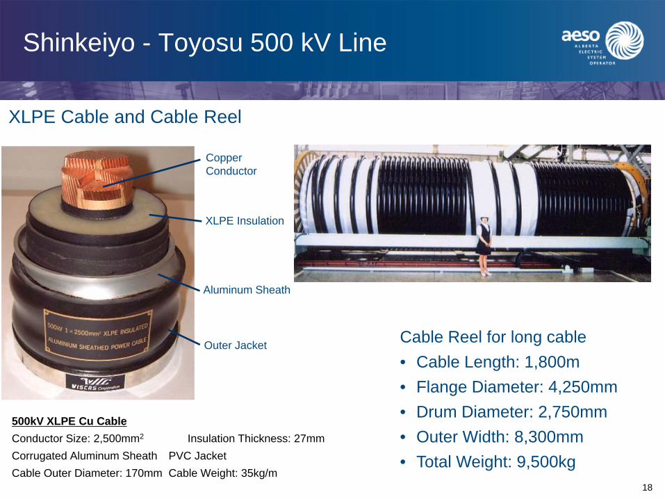
Shinkeiyo - Toyosu 500 kV Line
500kV XLPE Cu CableConductor Size: 2,500mm2 Insulation Thickness: 27mmCorrugated Aluminum Sheath PVC JacketCable Outer Diameter: 170mm Cable Weight: 35kg/m
Copper Conductor
XLPE Insulation
Aluminum Sheath
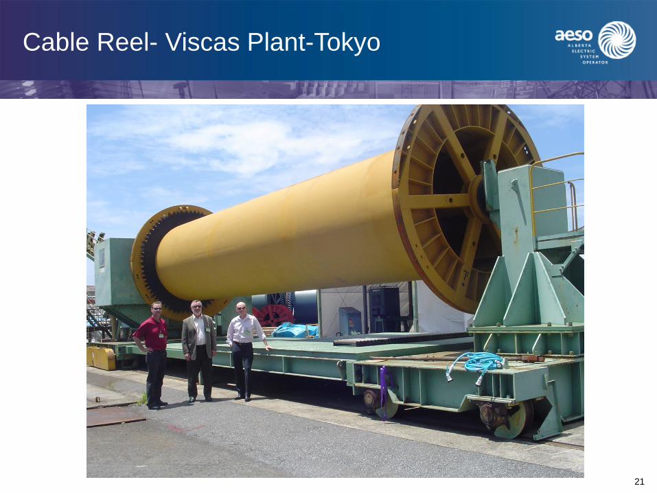
Outer Jacket Cable Reel for long cable• Cable Length: 1,800m• Flange Diameter: 4,250mm• Drum Diameter: 2,750mm• Outer Width: 8,300mm• Total Weight: 9,500kg
XLPE Cable and Cable Reel
19
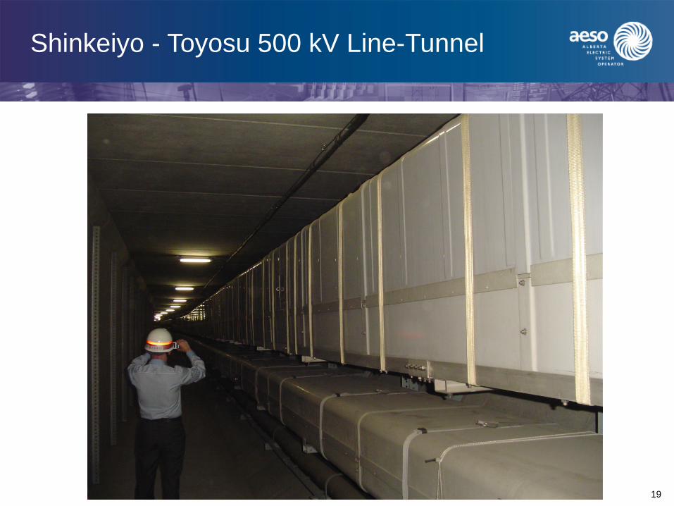
Shinkeiyo - Toyosu 500 kV Line-Tunnel
20
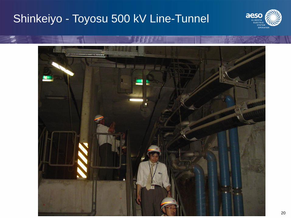
Shinkeiyo - Toyosu 500 kV Line-Tunnel
21
Cable Reel- Viscas Plant-Tokyo
22
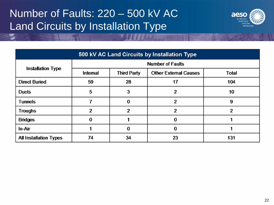
Number of Faults: 220 – 500 kV AC Land Circuits by Installation Type

23
System Factors - Thermal Transfer Capabilities (3,000 MVA)
0
500
1000
1500
2000
2500
3000
3500
10 20 30 40 50 60 70 80
Underground cable lengths (km)
Effe
ctiv
e P
ower
Tra
nsfe
r C
apab
ility
(MV
A)
0
500
1000
1500
2000
2500
3000
3500
4000
Char
ging
MV
A
All O/H 75 Charging MVA3x1590
All O/H 3x15903499 MVA
Charging MVA
Effective Power Transfer MVAWith Reactors
Effective Power Transfer MVAWithout Reactors
O/H – 3 x 1590 MCM ACSRU/G – 2 x 2500 mm2
24
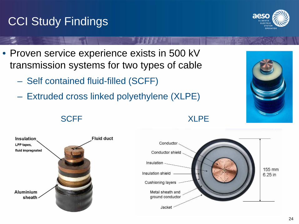
CCI Study Findings
• Proven service experience exists in 500 kV transmission systems for two types of cable
– Self contained fluid-filled (SCFF)
– Extruded cross linked polyethylene (XLPE)
SCFF XLPE
25
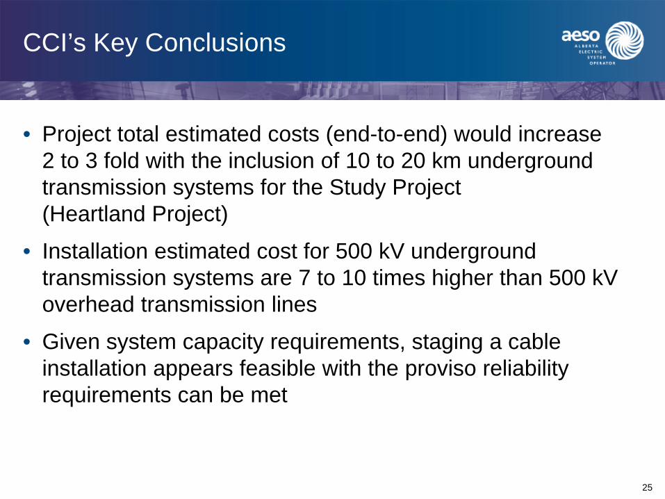
CCI’s Key Conclusions
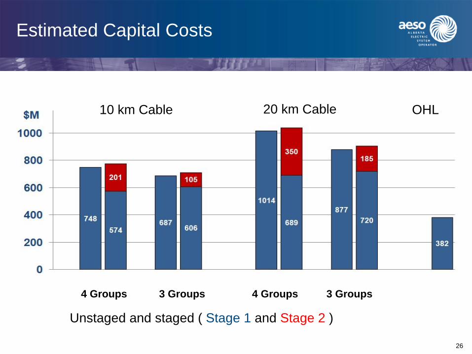
• Project total estimated costs (end-to-end) would increase 2 to 3 fold with the inclusion of 10 to 20 km underground transmission systems for the Study Project (Heartland Project)
• Installation estimated cost for 500 kV underground transmission systems are 7 to 10 times higher than 500 kV overhead transmission lines
• Given system capacity requirements, staging a cable installation appears feasible with the proviso reliability requirements can be met
26
Estimated Capital Costs
4 Groups 3 Groups
10 km Cable 20 km Cable OHL
4 Groups 3 Groups
Unstaged and staged ( Stage 1 and Stage 2 )
27
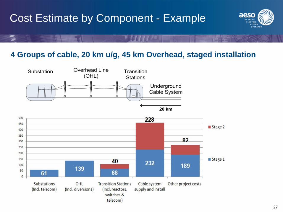
Cost Estimate by Component - Example
4 Groups of cable, 20 km u/g, 45 km Overhead, staged installation
28
CCI’s Key Conclusions
• Lifecycle cost analysis (40 years) concludes that the all-overhead line solution remains the lower cost alternative
• 500 kV underground transmission system is technically complex and typically involves custom design for each application
• Given the limited world experience with 500 kV underground, reliability of 500 kV cable systems is difficult to assess- Additional analysis is required
- May require redundancy

29
Lifecycle Cost Estimates
10 km cable20 km cable
OHL
4 Groups 3 Groups 4 Groups 3 Groups
NPV values – Losses shown in Red
Unstaged and staged
30
CCI’s Key Conclusions
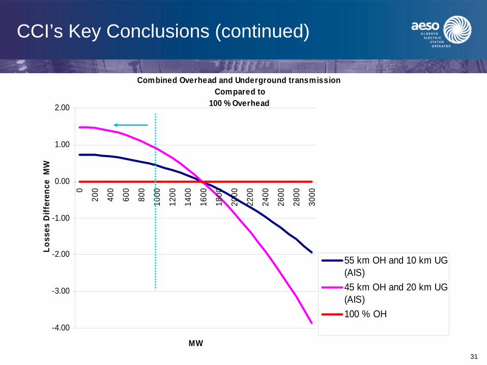
• Introduction of a 500 kV cable system does not result in added savings in system losses given the projected loading of the 500 kV lines will generally remain below 1,700 MW, as illustrated by the following graph
31
CCI’s Key Conclusions (continued)
Combined Overhead and Underground transmission Compared to
100 % Overhead
-4.00
-3.00
-2.00
-1.00
0.00
1.00
2.00
0
200
400
600
800
1000
1200
1400
1600
1800
2000
2200
2400
2600
2800
3000
MW
Loss
es D
iffer
ence
MW
55 km OH and 10 km UG(AIS)45 km OH and 20 km UG(AIS)100 % OH
32
CCI’s Key Conclusions (continued)
• 500 kV XLPE underground cable application is feasible for a 10 to 20 km application at Heartland
• Cable joint development for low temperature operation remains to be proven by manufacturers. Prequalification tests will need to be commissioned
• A fully tested and proven “off the shelf” 500 kV cable system does not exist for the Heartland application
• The Heartland 500 kV underground project is ranked as a world leading application by virtue of its rating (3,000 MVA) and its location specific requirements
33
Continued Work Activities
• AltaLink/EPCOR filed facility applications for the Heartland Project on September 27, 2010
– Recommended alternative is an overhead solution, however the application includes information regarding 500 kV AC underground
• AltaLink continuing with investigative work on 500 kV underground cable, including supplier preliminary qualification as well as test lab prequalification
34
Questions and References
• Full report on 500 kV AC underground study available at www.aeso.ca
• Report was released on February 24, 2010


