CFM PROPRIETARY INFORMATIONSubject to restrictions on the cover or first pa ge
�������������� ���������������
����������������������������
�������������� ���������������
����������������������������
6
Flight Operations Support10 September 2005
CFM PROPRIETARY INFORMATIONSubject to restrictions on the cover or first pa ge
The CFM56 core is based on the GE F101 engine(developed for the B-1 bomber) and employs a single-stage high-pressure turbine to drive a nine-stage compressor. Correspondingly, a Snecma advanced four- or five-stage, low-pressure turbine drives the Snecma fan and booster.
- LP system- Installations- Gearbox
- Controls and accessories
- Core engine- System integration- FADEC/MEC systems
A jointly owned companyEFECTIVE 50/50
WORK SPLIT
An effective division of labor dictates exactlyhow the companiesallocate theirmanufacturingresources. This worksplit acknowledges the technologicalachievements of bothSnecma's and GE Aircraft Engines' respective organizations
CFM GeneralCFM General
7
Flight Operations Support10 September 2005
CFM PROPRIETARY INFORMATIONSubject to restrictions on the cover or first pa ge
CFM PROPRIETARY INFORMATIONSubject to restrictions on the cover or first pa ge
CFM56-5B/PCFM56-5B/PIMPROVEMENTSIMPROVEMENTS
1
2
31. HPC3-D aero HPC compressor
2. HPTLatest HPT blade design
• Increased cooling
3. LPTRedesigned New LPT stage 1 nozzle
Key ChangesKey Changes
18
Flight Operations Support10 September 2005
CFM PROPRIETARY INFORMATIONSubject to restrictions on the cover or first pa ge
-5B1/P 30 Klbs
-5B2/P 31 Klbs
-5B3/P 32 Klbs
-5B4/P 27 Klbs
-5B5/P 22 Klbs
-5B6/P 23.5 Klbs
-5B7/P 27 Klbs
-5B8/P 21.6 Klbs
-5B9/P 23.3 Klbs
A321
A320
A319
A318
SAME ENGINE FOR 4 A/C APPLICATIONS
Engine Ratings & ApplicationsEngine Ratings & ApplicationsCFM56-5B FamilyCFM56-5B Family
Thrust rating
CFM56-5BX/P CFM56-5BX/2P
New 3D aéro design
DAC option
19
Flight Operations Support10 September 2005
CFM PROPRIETARY INFORMATIONSubject to restrictions on the cover or first pa ge
CFM56-5B3/P NameplateCFM56-5B3/P Nameplate
�The reference certified thrust level at Take Off for CFM56-5B3/P is 32,000lbf (nameplate)
• It corresponds to a sea level static thrust level
�The CFM56-5B3/P thrust rating has a Mach Bump to maximize aircraft performance
Thrust
equivalent toequivalent to Current 5B3/P rating ( including Mach Bump)Current 5B3/P rating ( including Mach Bump)
33,000lbf33,000lbf
32,000lbf32,000lbf
Usual fixed ratingMach Number
�To emphasize the real capacity of the engine during T/O phase, CFM marketed its CFM56-5B3/P engine as an equivalent 33,000lbf T/O thrust engine.
6422H - 03/01
20
Flight Operations Support10 September 2005
CFM PROPRIETARY INFORMATIONSubject to restrictions on the cover or first pa ge
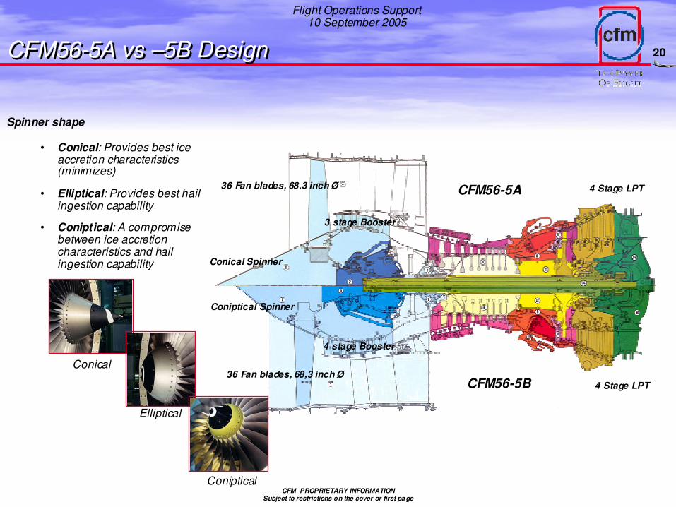
CFM56-5A vs –5B DesignCFM56-5A vs –5B Design
CFM56-5A
CFM56-5B36 Fan blades, 68,3 inch Ø
Coniptical Spinner
4 Stage LPT
4 stage Booster
36 Fan blades, 68.3 inch Ø
3 stage Booster
Conical Spinner
4 Stage LPT
Spinner shape
• Conical: Provides best ice accretion characteristics (minimizes)
• Elliptical: Provides best hail ingestion capability
• Coniptical: A compromise between ice accretion characteristics and hail ingestion capability
Conical
Elliptical
Coniptical
21
Flight Operations Support10 September 2005
CFM PROPRIETARY INFORMATIONSubject to restrictions on the cover or first pa ge
Engine Control SystemEngine Control System
Engine Air Contr ol System
Engine Fuel C ontrol System
Engi ne
State
/ Req u
e st
Ai craf t S
tat e / Reques
t
Pilot Requ
est2
1
Pilot Request
FMC
Eng
ineS
ensors
ECU
HMU
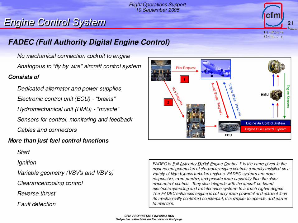
FADEC (Full Authority Digital Engine Control)
No mechanical connection cockpit to engine
Analogous to “fly by wire” aircraft control system
Consists of
Dedicated alternator and power supplies
Electronic control unit (ECU) - “brains”
Hydromechanical unit (HMU) - “muscle”
Sensors for control, monitoring and feedback
Cables and connectors
More than just fuel control functions
Start
Ignition
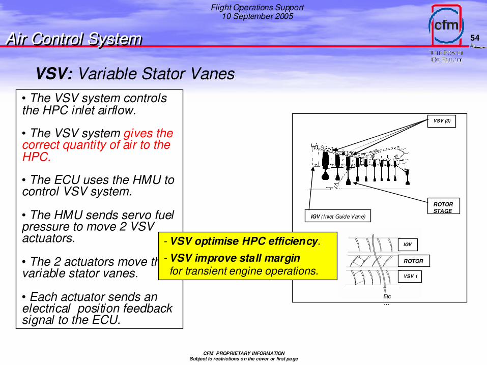
Variable geometry (VSV’s and VBV’s)
Clearance/cooling control
Reverse thrust
Fault detection
FADEC is Full Authority Digital Engine Control. It is the name given to the most recent generation of electronic engine controls currently installed on a variety of high-bypass turbofan engines. FADEC systems are more responsive, more precise, and provide more capability than the older mechanical controls. They also integrate with the aircraft on-board electronic operating and maintenance systems to a much higher degree. The FADEC enhanced engine is not only more powerful and efficient than its mechanically controlled counterpart, it is simpler to operate, and easier to maintain.
22
Flight Operations Support10 September 2005
CFM PROPRIETARY INFORMATIONSubject to restrictions on the cover or first pa ge
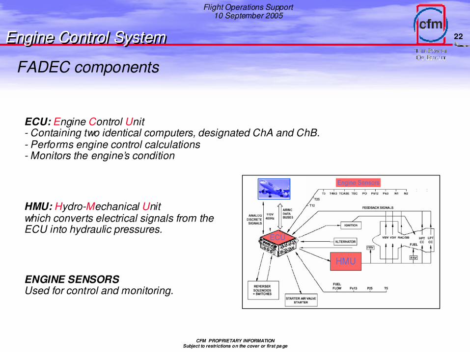
FADEC components
ECU: Engine Control Unit- Containing two identical computers, designated ChA and ChB.- Performs engine control calculations- Monitors the engine’s condition
ENGINE SENSORSUsed for control and monitoring.
HMU: Hydro-Mechanical Unitwhich converts electrical signals from the ECU into hydraulic pressures.
Engine Control SystemEngine Control System
23
Flight Operations Support10 September 2005
CFM PROPRIETARY INFORMATIONSubject to restrictions on the cover or first pa ge
EEC Functions:
• Performs input signal validation & processing• Governs the engine forward & reverse thrust• Performs automatic regulation• Provides information to airplane
( N1,2 red line / EGT red line, Max Cont, Start red line / ENG FAIL )
EEC Architecture:
• Dual channel• Cross-channel communication• Fault tolerant• Dual control sensors for critical inputs and feedback• Dual source airplane system inputs cross-connected to both channels
FADEC Philosophy
Engine Control SystemEngine Control System
- FADEC is a BITE system � Built In Test Equipment
- It detects and isolates failures or combinations of failures in order to determine the channel health status and to transmit maintenance data to the aircraft. Each channel determines itsown health status. The healthiest channel is selected as the active channel.
- The selection is based upon the health of each channel.Active / Stand-by channel selection is performed
- At EEC power-up and during operation.- At every engine start if equal health status exists ,as soon as N2>70%.
- If a channel is faulty and the channel in control is unable to ensure one engine function, this controlled function is moved to a fail-safe position.
Self-tested and fault tolerant
24
Flight Operations Support10 September 2005
CFM PROPRIETARY INFORMATIONSubject to restrictions on the cover or first pa ge
ActiveChannel
StandbyChannel
CCDL HMURegulated
EngineSystem
Feedback Signals
Feedback Signals
Torque motor current
Fuel Pressure
ECUECU
FADEC Philosophy
Engine Control SystemEngine Control System
Designed with a dual-redoundant architecture
25
Flight Operations Support10 September 2005
CFM PROPRIETARY INFORMATIONSubject to restrictions on the cover or first pa ge
All electrical inputs, sensors and feedback signals are dual
A A lostlost of of parameterparameter doesdoes not not generategenerate an ECU an ECU channelchannel change as long as the change as long as the CCDL CCDL isis operativeoperative
FADEC Philosophy
Engine Control SystemEngine Control System
26
Flight Operations Support10 September 2005
CFM PROPRIETARY INFORMATIONSubject to restrictions on the cover or first pa ge
Ch A
Ch B
CCDL
Single sensors ( PS13, P25, T5 )
Shared sensors( P0,PS12,PS3,EGT )
Dual sensors( N1, N2, T12,…)
All electrical inputs, sensors and feedback signals are dual
FADEC Philosophy
Engine Control SystemEngine Control System
27
Flight Operations Support10 September 2005
CFM PROPRIETARY INFORMATIONSubject to restrictions on the cover or first pa ge
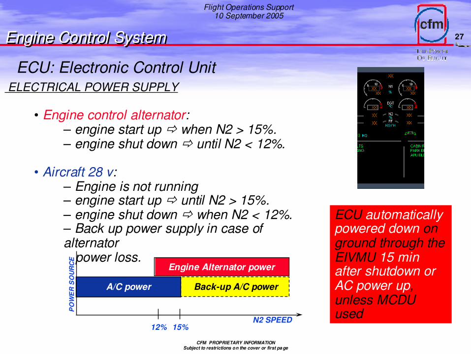
ELECTRICAL POWER SUPPLY
• Engine control alternator:– engine start up � when N2 > 15%.– engine shut down � until N2 < 12%.
• Aircraft 28 v:– Engine is not running– engine start up � until N2 > 15%.– engine shut down � when N2 < 12%.– Back up power supply in case of alternator
power loss.
12% 15%N2 SPEED
Engine Alternator power
A/C power Back-up A/C power
PO
WE
R S
OU
RC
E
ECU automatically powered down on ground through the EIVMU 15 min after shutdown or AC power up, unless MCDU used
Engine Control SystemEngine Control System
ECU: Electronic Control Unit
28
Flight Operations Support10 September 2005
CFM PROPRIETARY INFORMATIONSubject to restrictions on the cover or first pa ge
CFM56-5 Ignition SystemCFM56-5 Ignition System
�Features
• Two independent systems per engine
- Automatically alternated every two starts
• Ignition on - slightly before fuel
• Delayed ignition logic
• Either channel can control both ignition boxes
• Ignition off when N2 >50%
• Auto message if either ignition delayed/failed
• Auto relight if “flame-out” sensed
• Pilot can select continuous ignition
• Both ignitors on for all air starts and manual starts on the ground
• Ignitors located at the 4 and 8 o’clock position on combustion case
A Ign AECU Plugs
400Hz115V
B Ign B
29
Flight Operations Support10 September 2005
CFM PROPRIETARY INFORMATIONSubject to restrictions on the cover or first pa ge
10 Fuel Nozzles(Staged)
VSVVBVTBVHPTCCLPTCC
FUEL FLOW TRANSMITTER
BSV
Fuel nozzleFilter
Servo Fuel Pressure
Engine OilFrom Scavenge
Circuit
Engine OilBack ToOil Tank
HP PUMPFuel Filter
Metered Fuel
LP PUMP
IDG FUEL/OIL COOLER
FRV
T<100°c
MAIN OIL/FUEL HEAT EXCHANGER
(cools the engine scavenge oil)
SERVO FUEL HEATERRaises the T°of the fuel
10 Fuel Nozzles(Unstaged)
Fuel Control SystemFuel Control System
Fuel distribution
30
Flight Operations Support10 September 2005
CFM PROPRIETARY INFORMATIONSubject to restrictions on the cover or first pa ge
MAIN OIL/FUEL HEAT EXCHANGERFuel coming from LP pump cools the engine scavenge oil. The cooled engine oil returns to the oil tank.
SERVO FUEL HEATER Raises the T°of the fuel to eliminate ice in the fuel before entering the control servos, inside the HMU.Catch particles in suspension in the oil circuit, before the oil is coming back to the oil tank.
FUEL FLOW TRANSMITTERSignals are created and sent to:Ch A & Ch B of the ECU � ENGINE CONTROL
The DMCs for ECAM display in the flight deck � INDICATING
The FWCs for warning activation and display on ECAM �
4 wider spray pattern fuel nozzles placed adjacent to the igniters to help engine operation during start and adverse weather conditions.( 2 staged / 2 unstaged )
31
Flight Operations Support10 September 2005
CFM PROPRIETARY INFORMATIONSubject to restrictions on the cover or first pa ge
10 Fuel Nozzles(Staged)
FUEL FLOW TRANSMITTER
BSV
10 Fuel Nozzles(Unstaged)
Fuel nozzleFilter
• The BSV « Burner Staging Valve » controls fuel flow to the 10 staged fuel nozzles.
•The BSV will close in decel to keep the Wf abovethe lean flame out limit.
• With BSV closed, a stronger flow of fuel goes to the unstaged fuel nozzles. This makes a strongerflame pattern in the combustion chamber wichhelps to provide a better flameout margin at lowpower.
• At higher power, the BSV opens and lets fuel flow to the staged nozzles.
• BSV is remains open for these conditions:
• Engine at steady state on the ground• ECU cannot read the BSV position
BSV
Fuel Control SystemFuel Control System
32
Flight Operations Support10 September 2005
CFM PROPRIETARY INFORMATIONSubject to restrictions on the cover or first pa ge
4 wider spray pattern fuel nozzles placed adjacent to the igniters to help engine operation during start and adverse weather conditions.( 2 staged / 2 unstaged )
FUEL NOZZLES
Fuel Control SystemFuel Control System
43
Flight Operations Support10 September 2005
CFM PROPRIETARY INFORMATIONSubject to restrictions on the cover or first pa ge
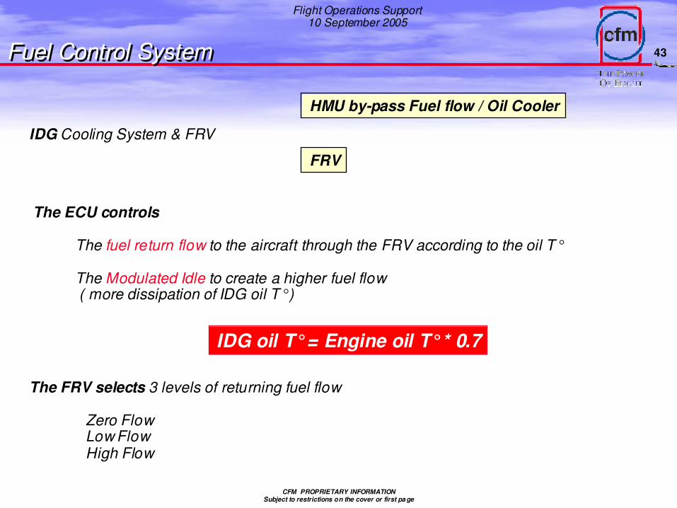
IDG Cooling System & FRV
HMU by-pass Fuel flow / Oil Cooler
FRV
The ECU controls
The fuel return flow to the aircraft through the FRV according to the oil T°
The Modulated Idle to create a higher fuel flow( more dissipation of IDG oil T°)
IDG oil T°= Engine oil T°* 0.7
The FRV selects 3 levels of returning fuel flow
Zero FlowLow FlowHigh Flow
Fuel Control SystemFuel Control System
44
Flight Operations Support10 September 2005
CFM PROPRIETARY INFORMATIONSubject to restrictions on the cover or first pa ge
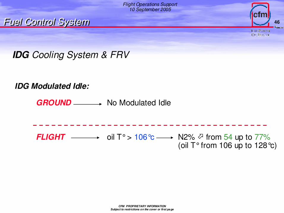
• The IDG cooling logic performs two functions:-The control of the FRV-The control of the mini N2
• Both functions cool the IDG oil by cooling the fuel that goes into the IDGoil/fuel heat exchanger.
• The FRV system returns hot fuel back to the aircraft fuel tanks.This enables cooler fuel to be pumped to improve the IDG oil cooling.
• The mini N2 controls the temperature by increasing the idle speed of theengine. The fuel T°� because of the additional flow, due to the N2 increase.
Fuel Control SystemFuel Control System
IDG Cooling System & FRV
45
Flight Operations Support10 September 2005
CFM PROPRIETARY INFORMATIONSubject to restrictions on the cover or first pa ge
GROUND oil T°> 90°c Low Returnuntil oil T°< 78°c
FLIGHT oil T°> 90°c Low Returnuntil oil T°< 78°c
oil T°> 95°c High Returnuntil oil T°< 85°cthen Low Return
CFM PROPRIETARY INFORMATIONSubject to restrictions on the cover or first pa ge
Engine CertificationEngine Certification
A variety of development and
certification tests are conducted on
CFM56 engines. Ground testing is
primarily accomplished by GEAE’s
Peebles Test Operation in Peebles,
Ohio and by comparable SNECMA
facilities in France like Saclay. Flight
testing is accomplished by GEAE’s
Flight Test Operation in Victorville,
California.
This presentation summarizes some of
these tests and test facilities used.
64
Flight Operations Support10 September 2005
CFM PROPRIETARY INFORMATIONSubject to restrictions on the cover or first pa ge
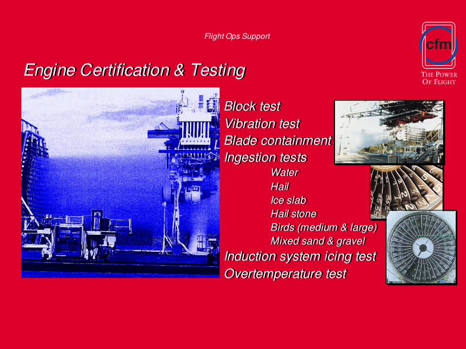
Test Objectives• Demonstrate fan blade containment inside casing• No fire accepted• Engine mounting attachments must not fail• Engine shut-down capacity within 15 sec.
Main goal is to show no hazard to the aircraft
Test description• Engine running at or above maximum allowed fan speed• 1 fan blade released : explosive in shank of released blade.
Engine CertificationEngine Certification
Blade containment test
65
Flight Operations Support10 September 2005
CFM PROPRIETARY INFORMATIONSubject to restrictions on the cover or first pa ge
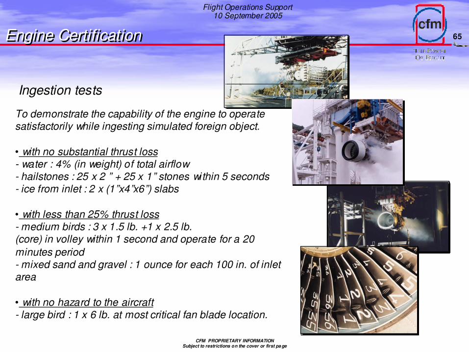
To demonstrate the capability of the engine to operate satisfactorily while ingesting simulated foreign object.
• with no substantial thrust loss- water : 4% (in weight) of total airflow- hailstones : 25 x 2 ” + 25 x 1” stones within 5 seconds- ice from inlet : 2 x (1”x4”x6”) slabs
• with less than 25% thrust loss- medium birds : 3 x 1.5 lb. +1 x 2.5 lb.(core) in volley within 1 second and operate for a 20 minutes period- mixed sand and gravel : 1 ounce for each 100 in. of inlet area
• with no hazard to the aircraft- large bird : 1 x 6 lb. at most critical fan blade location.
Engine CertificationEngine Certification
Ingestion tests
66
Flight Operations Support10 September 2005
CFM PROPRIETARY INFORMATIONSubject to restrictions on the cover or first pa ge
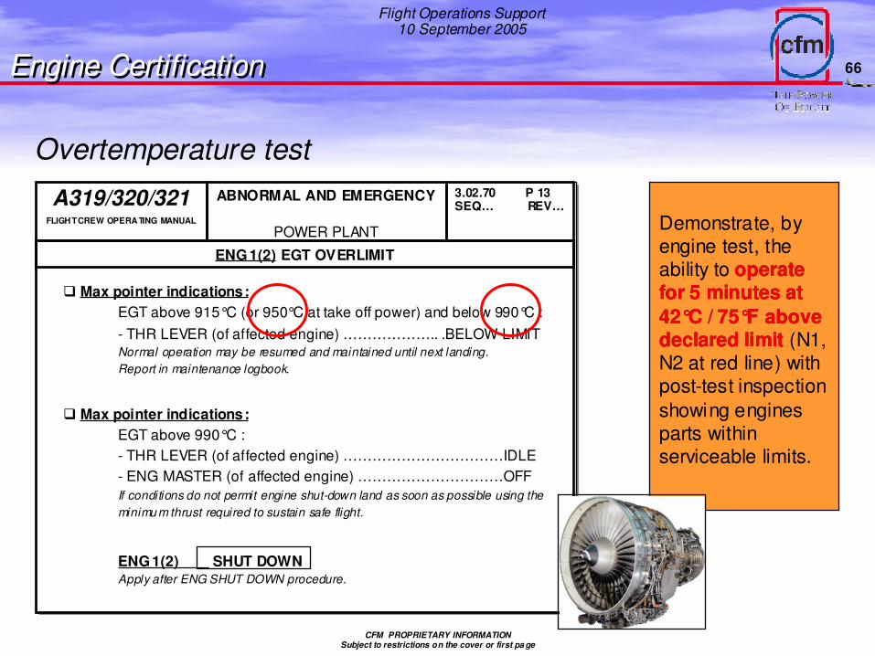
Demonstrate, by engine test, the ability to operate operate for 5 minutes at for 5 minutes at 4242°°C / 75C / 75°°F above F above declared limitdeclared limit (N1, N2 at red line) with post-test inspection showing engines parts within serviceable limits.
Overtemperature test
Engine CertificationEngine Certification
� Max pointer indications:EGT above 915°C (or 950°C at take off power) and below 990°C :- THR LEVER (of affected engine) ……………….. .BELOW LIMITNormal operation may be resumed and maintained until next landing.Report in maintenance logbook.
� Max pointer indications:EGT above 990°C :- THR LEVER (of affected engine) ……………………………IDLE- ENG MASTER (of affected engine) …………………………OFFIf conditions do not permit engine shut-down land as soon as possible using the minimu m thrust required to sustain safe flight.
ENG 1(2) SHUT DOWNApply after ENG SHUT DOWN procedure.
A319/320/321FLIGHT CREW OPERATING MANUAL
ABNORMAL AND EMERGENCY
POWER PLANT
3.02.70 P 13SEQ… REV…
ENG 1(2) EGT OVERLIMIT
67
Flight Operations Support10 September 2005
CFM PROPRIETARY INFORMATIONSubject to restrictions on the cover or first pa ge
Flight Ops Support
Technical FeaturesTechnical Features
Normal Operating ConsiderationsFlight phases, ops recommendations
Normal Operating ConsiderationsFlight phases, ops recommendations
CFM PROPRIETARY INFORMATIONSubject to restrictions on the cover or first pa ge
Power ManagementPower Management
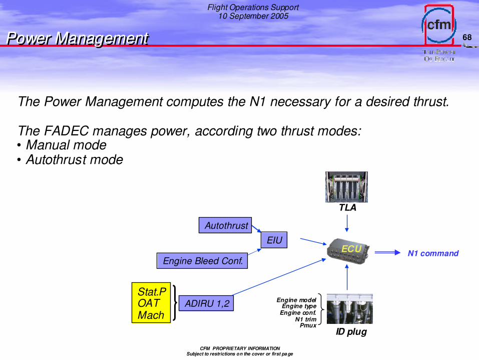
The Power Management computes the N1 necessary for a desired thrust.
The FADEC manages power, according two thrust modes:• Manual mode• Autothrust mode
Stat.POATMach
ECU
ADIRU 1,2
N1 command
ID plug
Engine modelEngine type
Engine conf.N1 trim
Pmux
TLA
EIU
Autothrust
Engine Bleed Conf.
69
Flight Operations Support10 September 2005
CFM PROPRIETARY INFORMATIONSubject to restrictions on the cover or first pa ge
• At engine idle speed, the bleed pressure must be at, or above the aircraft demand.
( Including flame out protection in bad weather )
• At engine idle speed, the N2 must satisfy:-Mini engine permissible core speed (N2=58.8%)-Mini accessories speed-Mini speed for IDG oil T°control
• Engine idle speed must comply with Modulated Idle-In flight, Flaps < 20°and Landing Gear retracted-On the ground to minimize the time to accelerate to maxi reverse
• Engine idle speed must comply with Approach Idle-Approach idle is the mini engine power possible when the mini Modulated Idle is not active.-The approach idle enables the engine to achieve the GO AROUND THRUST within 8s.
Idle Control
Power ManagementPower Management
70
Flight Operations Support10 September 2005
CFM PROPRIETARY INFORMATIONSubject to restrictions on the cover or first pa ge
The 8 baseline thrust ratings are calculated by the FADEC:
- MTO/GA Maxi Take off / Go Around- DRT Derate Take off- FLEX Flexible Take off- MCT Maxi Continuous- MCL Maxi Climb- DCL Derated Climb- IDLE Idle Level- MREV Maxi Reverse
Each rating sets a fan speed N1, and each baseline rating is associated with a throttle flat. Thrust levels between these baseline ratings are set by interpolation depending on TLA.
Power ManagementPower Management
71
Flight Operations Support10 September 2005
CFM PROPRIETARY INFORMATIONSubject to restrictions on the cover or first pa ge
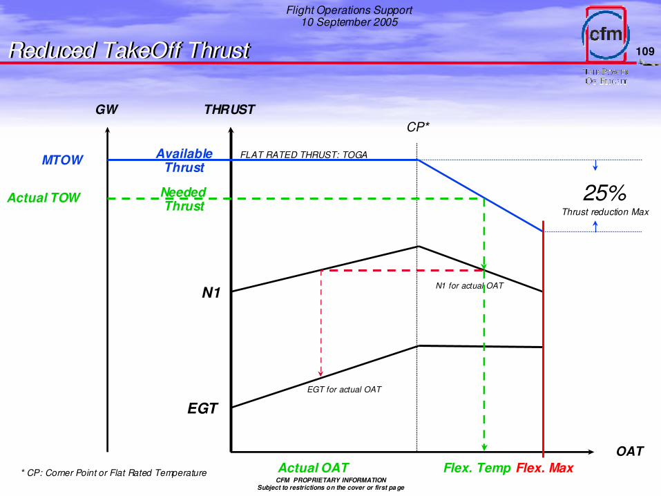
EGT
N1
FLAT RATED THRUST
Thrust(TOGA)
OAT
CP*ISA+15 or 29°C
* CP: Corner Point or Flat Rated Temperature
1. To meet aircraft performance requirements, the engine is designed to provide a given thrust level to some “Flat Rate”Temperature (FRT).
2. N1 for takeoff power management schedule increases with OAT (up to FRT) to maintain constant thrust. After FRT, power management N1 (and thrust) decreases.
3. EGT increases with OAT to FRT, then remains constant.
At a given OAT, 1%N, is equivalent to approximately 10oC of EGT.
Flat Rate ConceptPower ManagementPower Management
72
Flight Operations Support10 September 2005
CFM PROPRIETARY INFORMATIONSubject to restrictions on the cover or first pa ge
EGT
N1
FLAT RATED THRUST
Thrust(TOGA)
OAT
CP*ISA+15°C or 29°C
EGT RED LINE
EGT MARGIN is the difference between:
- EGT RED LINE&
- EGT observed on an engine at TOGA with a temperature ≥ CORNER POINT OAT
Throttles are advanced until target N1 is achieved. After throttle set, The Main Engine Control maintains the N2 corresponding to that throttle position. Because of different thermal characteristics of the core engine static and rotating components, the core becomes less efficient and a higher fuel flow and EGT is required to maintain N2. The increased energy available at the LPT causes N1 to increase: thus EGT and N1 “bloom”. As the thermal growth of core components stabilize, the core becomes more efficient and EGT and N1 will decrease (“droop”).
These transient characteristics are taken into account when determining power management N1 required to achieve aircraft performance. They are also taken into account when establishing operating limits for the engine.
Power ManagementPower Management
75
Flight Operations Support10 September 2005
CFM PROPRIETARY INFORMATIONSubject to restrictions on the cover or first pa ge
CFM56 PMC or FADEC Transient Characteristics
Throttleangle
N2
EGT
N1
Throttle set Time
The power management function on the CFM56 PMC and FADEC engines consists of controlling N1 (rather than N2) to produce thrust requested by the throttle position. The PMC and FADEC use the ambient conditions (total air temperature, total pressure and ambient pressure) and engine bleed requirements to calculate N1based on a throttle position. Additionally, FADEC modulates the variable bleed valves, variable stator vanes, bore cooling valves and HPT and LPT active clearance control valves to maximize engine efficiency during transient and steady state operations. As a result of this increased efficiency, the EGT bloom and droop are reduced.
Power ManagementPower Management
76
Flight Operations Support10 September 2005
CFM PROPRIETARY INFORMATIONSubject to restrictions on the cover or first pa ge
EGT Transient
EGT
Time
Throttle set
Margin Hydromechanical control
FADEC control
Red line
Power ManagementPower Management
77
Flight Operations Support10 September 2005
CFM PROPRIETARY INFORMATIONSubject to restrictions on the cover or first pa ge
If OATL < CPEGT exceedances may occur during a Full Power Takeoff
1°C OAT or Flex Temperature = 3,3°C EGT
EGTMargin & OATLEGTMargin & OATL
The OATL calculation for the CFM56-5B:(see Commercial Engine Service Memorandum)OATL = CP + EGTM / 3,3CFM56-5C Corner Point is ISA+15°Ce.g.: At Sea Level the OATL = 30 + EGTM / 3,3
950°C
78
Flight Operations Support10 September 2005
CFM PROPRIETARY INFORMATIONSubject to restrictions on the cover or first pa ge
EGT Transcientallowance to -5B EGT limits
Area A•If engine warm-up not sufficientNo troubleshooting. 20 overtemp permitted.•If EGT exceedance condition identifiedNo troubleshooting. 10 overtemp permitted.•If EGT exceedance condition can ’t be identifiedTroubleshooting. 10 exceedances permetted in area A & B combined before engine removal.
Area BTroubleshooting. 10 exceedances permetted in area A & B combined before engine removal
Area CThe engine must be removed to examine damage. One nonrevenue flight permitted if damage within boroscope inspection.
EGTMargin & OATLEGTMargin & OATL
79
Flight Operations Support10 September 2005
CFM PROPRIETARY INFORMATIONSubject to restrictions on the cover or first pa ge
• Temperature inversion
• Warm-up time
• Dirty compressor airfoils
• Engine deterioration
• Too much bleed air on the engine
• FOD
• Engine system malfunction
(e.g. VBV actuation)
• Engine hardware malfunction
Causes of EGT exceedancesTemperature invertion
EGT
N1
FLAT RATED THRUST
Thrust(TOGA)
OAT
CP*
* CP: Corner Point or Flat Rated Temperature
EGT Red line
EGTMargin & OATLEGTMargin & OATL
FADEC will control the engine according to the above charts. Below FRT, thrust would be maintained but N1 and EGT would be higher versus no inversion. Above FRT, some loss of thrust wouldoccur (not deemed significant by the aircraft manufacturers in terms of aircraft performance).
80
Flight Operations Support10 September 2005
CFM PROPRIETARY INFORMATIONSubject to restrictions on the cover or first pa ge
KEEP IN MIND
•Stick to your Flight Manual Procedures
• Certified thrust will indeed remain available even in case of EGT Exceedance
• At TOGA, ENG OVERTEMPERATURE may occur when:OAT ≥ OATL and the OATL ≤ CP (ISA+15°C)
• No EGT exceedances for performance deterioration as long as the OATL > CP (ISA+15°C)
• 1°C OAT or Flex Temperature = 3,3°C EGT• OATL data:
- helps the crew to assess potential EGT exceedances- is the primary basis for the scheduling of engine removal
EGTMargin & OATLEGTMargin & OATL
81
Flight Operations Support10 September 2005
CFM PROPRIETARY INFORMATIONSubject to restrictions on the cover or first pa ge
??
When When EGTMarginEGTMargin decrease,decrease,Fuel Burn increase.Fuel Burn increase.
+ 10+ 10°° EGT = + 0.7% SFCEGT = + 0.7% SFC
ENGINES contribute...
…
Performance DeteriationPerformance Deteriation
… to AIRCRAFT performance deterioration
~ 66 %~ 66 %
82
Flight Operations Support10 September 2005
CFM PROPRIETARY INFORMATIONSubject to restrictions on the cover or first pa ge
CFM PROPRIETARY INFORMATIONSubject to restrictions on the cover or first pa ge
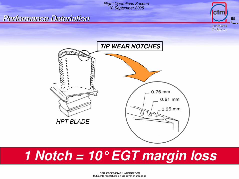
TIP WEAR NOTCHES
HPT BLADE
1 Notch = 10°EGT margin loss
Performance DeteriationPerformance Deteriation
86
Flight Operations Support10 September 2005
CFM PROPRIETARY INFORMATIONSubject to restrictions on the cover or first pa ge
TAKE CARE OF YOUR ENGINES…
… AND KEEP YOURAIRCRAFT SAFE !!!
… YOU WILL SAVEMONEY…
Performance DeteriationPerformance Deteriation
87
Flight Operations Support10 September 2005
CFM PROPRIETARY INFORMATIONSubject to restrictions on the cover or first pa ge
REDUCEDREDUCEDTAKE OFF THRUSTTAKE OFF THRUST
Flight Ops Support
Reduced TakeOff ThrustReduced TakeOff Thrust
88
Flight Operations Support10 September 2005
CFM PROPRIETARY INFORMATIONSubject to restrictions on the cover or first pa ge
Technical terms
RATED TAKE OFF THRUST (FAA AC 25-13)The approved Engine Thrust (Name Plate)
TAKE OFF THRUST (FAA AC 25-13)The Engine Rated Take Off Thrust or corrected
Derated Takeoff ThrustLevel less than the max. takeoff thrust. The value is considered a normal take off operating limit.
Reduced Takeoff ThrustLevel less than the max. takeoff or Derated Take Off thrust. The thrustsetting parameter is not considered a takeoff operating limit.Is at least 75% of the max. takeoff or Derated Take Off thrust.
RERATINGIs a manufacturer action changing the approved engine thrust (Name Plate)
Reduced TakeOff ThrustReduced TakeOff Thrust
89
Flight Operations Support10 September 2005
CFM PROPRIETARY INFORMATIONSubject to restrictions on the cover or first pa ge
Reduced TakeOff ThrustReduced TakeOff Thrust
90
Flight Operations Support10 September 2005
CFM PROPRIETARY INFORMATIONSubject to restrictions on the cover or first pa ge
Reduced Thrust Versus Derate
� Reduced thrust takeoff
• V-speeds used protect minimum control speeds (VMCG, VMCA) for full thrust
• Reduced thrust setting is not a limitation for the takeoff, I.e., full thrust may be selected at any time during the takeoff
� Derated takeoff
• Takeoff at a thrust level less than maximum takeoff for which separate limitations and performance data exist in the AFM. Corresponds to an “alternate” thrust rating
• V-speeds used protect minimum control speeds (VMCG, VMCA) for the deratedthrust . . . not original maximum takeoff thrust
• The derated thrust setting becomes an operating limitation for the takeoff
� On some installations derated thrust and reduced thrust can be used together, e.g., a derated thrust can be selected and thrust further reduced using the Flex temperature method
Reduced TakeOff ThrustReduced TakeOff Thrust
91
Flight Operations Support10 September 2005
CFM PROPRIETARY INFORMATIONSubject to restrictions on the cover or first pa ge
-40%
-35%
-30%
-25%
-20%
-15%
-10%
-5%
0%
0 5 10 15 20 25 30 35 40
Delta Assumed Te mpera ture Be yond Corner Point (deg C)
Reduced TakeOff ThrustReduced TakeOff ThrustThrust Reduction Vs. Flex/Assumed Temperature
92
Flight Operations Support10 September 2005
CFM PROPRIETARY INFORMATIONSubject to restrictions on the cover or first pa ge
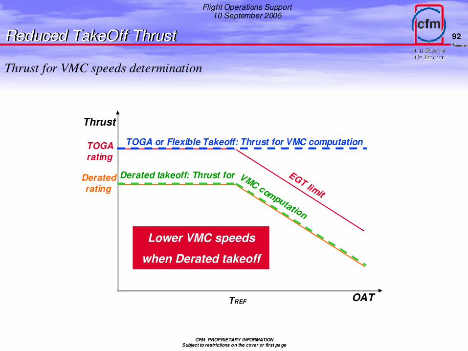
Thrust for VMC speeds determination
Thrust
OAT
EGT limit
TREF
TOGArating
Deratedrating
Derated takeoff: Thrust for VMC computation
TOGA or Flexible Takeoff: Thrust for VMC computation
Lower VMC speedsLower VMC speeds
when when DeratedDerated takeofftakeoff
Reduced TakeOff ThrustReduced TakeOff Thrust
93
Flight Operations Support10 September 2005
CFM PROPRIETARY INFORMATIONSubject to restrictions on the cover or first pa ge
TORA/TODA/ASDA
MTO
W TOGA
D04
D08
D12
D16
D20
D24
MTOW with Derated takeoff
Given runway length
MTOW for TOGA takeoff
MTOW for D12 (Derated takeoff)
Reduced TakeOff ThrustReduced TakeOff Thrust
94
Flight Operations Support10 September 2005
CFM PROPRIETARY INFORMATIONSubject to restrictions on the cover or first pa ge
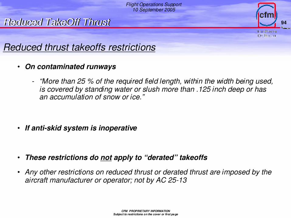
Reduced thrust takeoffs restrictions
• On contaminated runways
- “More than 25 % of the required field length, within the width being used, is covered by standing water or slush more than .125 inch deep or has an accumulation of snow or ice.”
• If anti-skid system is inoperative
• These restrictions do not apply to “derated” takeoffs
• Any other restrictions on reduced thrust or derated thrust are imposed by the aircraft manufacturer or operator; not by AC 25-13
Reduced TakeOff ThrustReduced TakeOff Thrust
95
Flight Operations Support10 September 2005
CFM PROPRIETARY INFORMATIONSubject to restrictions on the cover or first pa ge
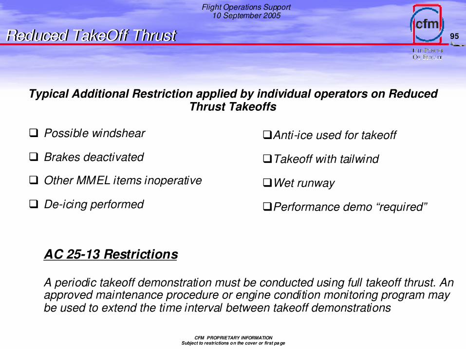
Typical Additional Restriction applied by individual operators on Reduced Thrust Takeoffs
� Possible windshear
� Brakes deactivated
� Other MMEL items inoperative
� De-icing performed
Reduced TakeOff ThrustReduced TakeOff Thrust
AC 25-13 Restrictions
A periodic takeoff demonstration must be conducted using full takeoff thrust. An approved maintenance procedure or engine condition monitoring program may be used to extend the time interval between takeoff demonstrations
�Anti-ice used for takeoff
�Takeoff with tailwind
�Wet runway
�Performance demo “required”
96
Flight Operations Support10 September 2005
CFM PROPRIETARY INFORMATIONSubject to restrictions on the cover or first pa ge
� Operator methods vary e.g.
• Every tenth takeoff
• Every Friday
• Never make dedicated full thrust T/O for performance verification
- Take credit for ECM and full thrust T/O’s performed for operational reasons
� Less reduced thrust benefits acrue when unnecessary full thrust takeoffs are performed
� Full thrust takeoffs meaningful only when takeoff is performed at the flat rate temperature; otherwise the
takeoff data must be extrapolated to flat rate temperature
• Reduced thrust takeoffs can be extrapolated as well
• Cruise ECM data can also be used to predict EGT margin
� Negotiate with regulatory agency to extend interval between dedicated performance verification takeoffs
• Take credit for ECM programs (T/O or Cruise)
• Take credit for full thrust takeoffs performed for operational requirements
• Extrapolate data obtained during reduced thrust as well as full thrust takeoffs
CFM PROPRIETARY INFORMATIONSubject to restrictions on the cover or first pa ge
- Max Thrust is not any more necessary!
Benefits of Reduced Thrust/Derated
- Lower Takeoff EGT
- Fewer operational events due to high EGT
- Lower fuel burn over on-wing life of engine
- Lower maintenance costsEGTMargin decrease slowly � SFC kept at low rateBetter Engine performance retention � - Longer engine life on wing
- Shop Visit rate decrease- Improved flight safetyFor a given TakeOff, engine stress decreasing,probability of engine failure decrease on that TakeOff.
TakeOff thrust is reduced when REAL GW < MAX LIMITING GW
Reduced TakeOff ThrustReduced TakeOff Thrust
98
Flight Operations Support10 September 2005
CFM PROPRIETARY INFORMATIONSubject to restrictions on the cover or first pa ge
Reduced TakeOff ThrustReduced TakeOff Thrust
Three engine parameters that determine the degree of engine severity are rotor speeds, internal temperature and internal pressure. Operating an engine at a lower thrust rating or at reduced thrust reduces the magnitude of these parameters, thus reducing engine severity.
Less severe operation tends to lower EGT deterioration. Since lack of EGT margin is one cause of scheduled engine removals, lowering the EGT deterioration rate can increase the time on wing between shop visits.
Fuel flow deterioration rate varies directly with EGT deterioration rate, thus decreasing with the use of reduced thrust.
Maintenance costs are reduced because of the longer time between shop visits and the lower labor and material costs of the shop visit to restore the engine to a specified condition.
Finally, reduced thrust on a given takeoff reduces stress level and likelihood of an engine failure on that takeoff.
99
Flight Operations Support10 September 2005
CFM PROPRIETARY INFORMATIONSubject to restrictions on the cover or first pa ge
CFM56-5B/P 5B3 Engine Parameters(Full Versus Reduced Thrust)
At Sea Level, Flat Rate Temperature of 30oC, 0.25 M ach, Typical New Engine
100
Flight Operations Support10 September 2005
CFM PROPRIETARY INFORMATIONSubject to restrictions on the cover or first pa ge
Reduced TakeOff ThrustReduced TakeOff ThrustEGTMargin and SFC deterioration vs Thrust Rating
Increasi ng
EGTDeteriorati on
Rate
EGT Deterioration
SL Static Takeoff Thrust Rating Increasi ng
Increasi ng
FFDeteriorati on
Rate
Fuel Flow Deteriorati on
SL Static Takeoff Thrust Rating Increasi ng
Although we do not have empirical data to allow us to plot EGTM/SFC deterioration or Cycles to Shop Visit versus derate , we do know that for different thrust ratings of the same engine model the deterioration rate tends to be greater on the higher thrust ratings. This concept is shown in the above and across charts.
Increasi ng
Cycles toShop Visit
Cycles to Shop Visit
SL Static Takeoff Thrust Rating Increasi ng
101
Flight Operations Support10 September 2005
CFM PROPRIETARY INFORMATIONSubject to restrictions on the cover or first pa ge
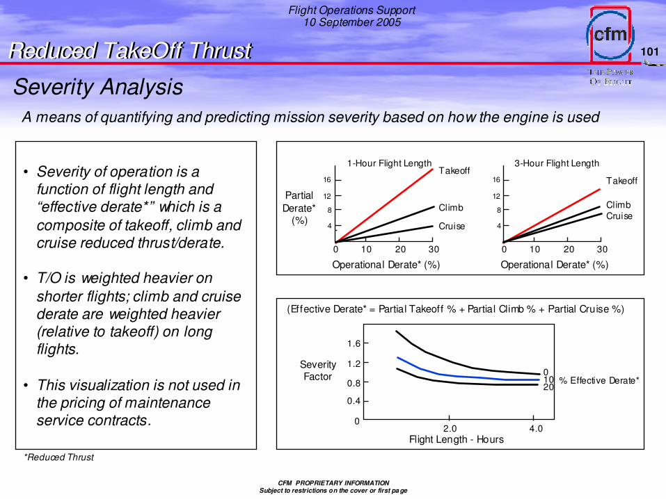
• Severity of operation is a function of flight length and “effective derate*” which is a composite of takeoff, climb and cruise reduced thrust/derate.
• T/O is weighted heavier on shorter flights; climb and cruise derate are weighted heavier (relative to takeoff) on long flights.
• This visualization is not used in the pricing of maintenance service contracts.
Severity Analysis
*Reduced Thrust
A means of quantifying and predicting mission severity based on how the engine is used
Reduced TakeOff ThrustReduced TakeOff Thrust
102
Flight Operations Support10 September 2005
CFM PROPRIETARY INFORMATIONSubject to restrictions on the cover or first pa ge
Estimated Severity Reduction Dueto the Use of Reduced Climb Thrust
EstimatedSeverity
Reduction -%
2-Hour Flight LegTakeoff D erate = 10%Cruise Derate = 10%
Average Climb Derate Thrust - %
0 5 10 15 20 25
Takeoff
Climb
Severity Analysis
Reduced TakeOff ThrustReduced TakeOff Thrust
This chart shows that the impact of climb thust reduction on severity, while still positive, is not as great as for takeoff thrust reduction.
Although climb thrust reduction may reduce engine severity, its use may actually increase fuel burn on a given flight because of the lesser time spent in the highly fuel efficient cruise phase of flight.
103
Flight Operations Support10 September 2005
CFM PROPRIETARY INFORMATIONSubject to restrictions on the cover or first pa ge
Estimated Severity R eduction Dueto the Use of Reduced Takeoff Thrust
0 5 10 15 20 25
EstimatedSeverity
Reduc tion -%
Average Takeoff R educed Thrus t - %
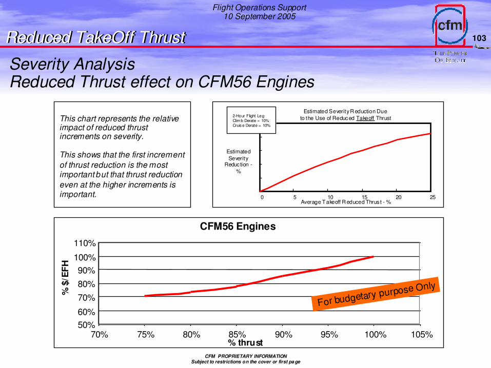
This chart represents the relative impact of reduced thrust increments on severity.
This shows that the first increment of thrust reduction is the most important but that thrust reduction even at the higher increments is important.
Severity Analysis
Reduced TakeOff ThrustReduced TakeOff Thrust
CFM56 Engines
50%60%
70%80%90%
100%
110%
70% 75% 80% 85% 90% 95% 100% 105%% thrust
% $
/EFH
For budgetary purpose Only
2-Hour Flight LegClim b Derate = 10%Cruis e Derate = 10%
Reduced Thrust effect on CFM56 Engines
104
Flight Operations Support10 September 2005
CFM PROPRIETARY INFORMATIONSubject to restrictions on the cover or first pa ge
Flight Leg
100
80
60
40
20
00.5 1.5 2.5 321
% E
ngin
e M
aint
enan
ce C
ost
T/OFFCLIMBCRUISE
T/OFFCLIMBCRUISE
Lower maintenance costs
1 minute of takeoff has a responsibility of at least 45% at least on the engine maintenance cost
Reduced TakeOff ThrustReduced TakeOff Thrust
105
Flight Operations Support10 September 2005
CFM PROPRIETARY INFORMATIONSubject to restrictions on the cover or first pa ge
Note: - Data for entire high-bypass engine-powered commercial transport fleet - Source: « Propulsion Safety Analysis Methodology for Commercial Transport Aircraft », 1998
Improved flight safety
Example: For an average high bypass turbofan mission (approximately 2 hours) 43% of the uncontained engine failures occur in the 1% of the time spent in the takeoff phase. This yields an “uncontained factor” of 43÷1 = 43 versus the “uncontained factor” for climb which is 30÷14 ~ 2. Thus, on uncontained failure is 21.5 times more likely to occur in the takeoff (higher thrust) phase than the climb (lower thrust) phase of flight. To make the point that an engine failure is less likely at reduced thrust, one can think of the takeoff phase as a “full thrust” takeoff and the climb phase as “reduced thrust.” Thus, the data would show a significantly higher chance of engine failure at full thrust than reduced thrust.
• No data on Thrust Reduction versus engine failures
• Following data is for takeoff phase Vs climb phase, showing significantly higher chance of engine failure at higher thrust settings associated with takeoff
Reduced TakeOff ThrustReduced TakeOff Thrust
106
Flight Operations Support10 September 2005
CFM PROPRIETARY INFORMATIONSubject to restrictions on the cover or first pa ge
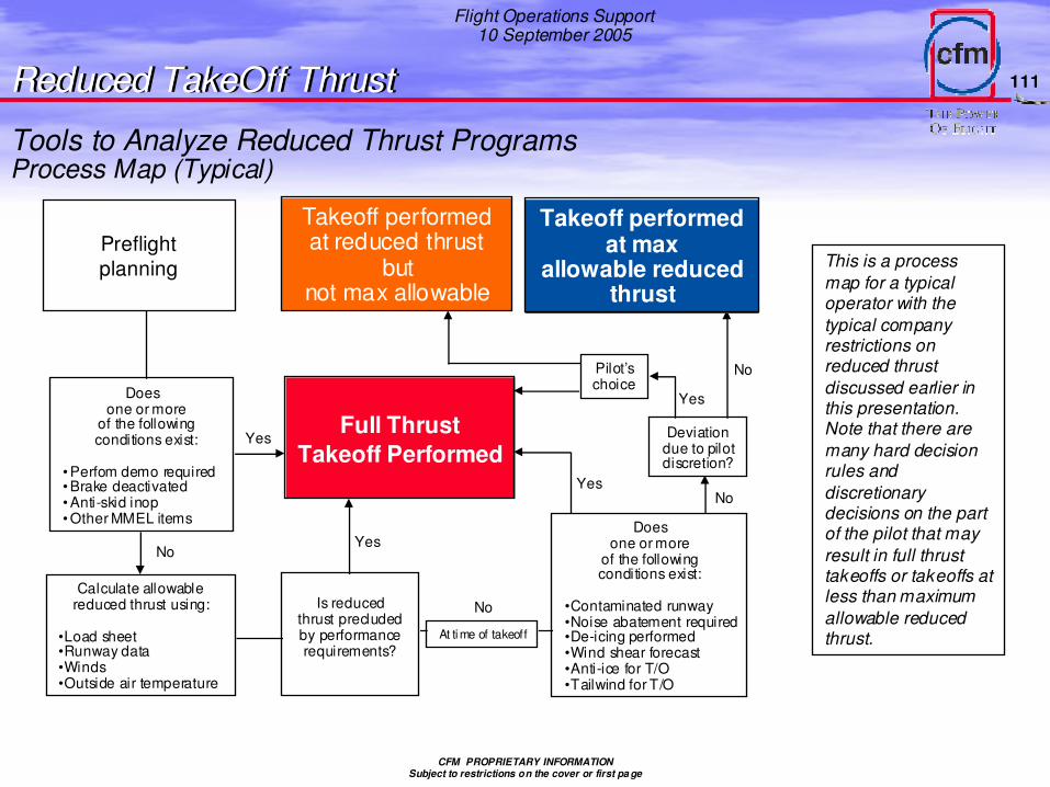
•Load sheet•Runway data•Winds•Outside air temperature
Is reducedthrust precludedby performancerequirements?
At time of takeoff
Doesone or more
of the followingconditions exist:
•Contaminated runway•Noise abatement required•De-icing performed•Wind shear forecast•Anti-ice for T/O•Tailwind for T/O
Pilot’s choice
Takeoff performed at max
allowable reduced thrust
Takeoff performed at reduced thrust
butnot max allowable
Full ThrustTakeoff Performed
Yes
NoYes
Yes
No
No
No
Yes
Deviationdue to pilotdiscretion?
This is a process map for a typical operator with the typical company restrictions on reduced thrust discussed earlier in this presentation. Note that there are many hard decision rules and discretionary decisions on the part of the pilot that may result in full thrust takeoffs or takeoffs at less than maximum allowable reduced thrust.
Tools to Analyze Reduced Thrust ProgramsProcess Map (Typical)
Reduced TakeOff ThrustReduced TakeOff Thrust
112
Flight Operations Support10 September 2005
CFM PROPRIETARY INFORMATIONSubject to restrictions on the cover or first pa ge
Reduced TakeOff ThrustReduced TakeOff Thrust
For a given takeoff, there is obviously more performance margin at full
thrust than at reduced thrust, however:
Reduced thrust takeoffs meet or exceed all the performance
requirements of the Regulatory Agencies
For a reduced thrust takeoff at a given Flex/Assumed Temperature,
the performance margin is greater than for a full thrust takeoff at an
ambient temperature equal to the Assumed Temperature
Performance Aspects
114
Flight Operations Support10 September 2005
CFM PROPRIETARY INFORMATIONSubject to restrictions on the cover or first pa ge
THE Flex T°METHOD ALWAYS CONSERVATIVEON THE AIRCRAFT PERFORMANCES.
Air T°= 10°& � TAS = 138.5 KtsV1 CAS = 140 Kts
Due to lower ambient temperature and higher air density in the actual takeoff conditions, actual TAS is lower and actual thrust is higher
Flex T°= 55°& � TAS = 151.5 KtsV1 CAS = 140 Kts
Example:
The Speed used to comply with the performance calculations!
The Speed you will have...
(+ if T°> Std, - if T°< Std)TAS = CAS +/- 1% ��5°c / Std
Reduced TakeOff ThrustReduced TakeOff Thrust
115
Flight Operations Support10 September 2005
CFM PROPRIETARY INFORMATIONSubject to restrictions on the cover or first pa ge
Distance from start of roll
V1 CAS = 140 Kts
V1 TAS = 151.5 Kts
Air T°= 55°cV1 CAS = 140 Kts
V1 TAS = 138.5 Kts
Air T°= 10°c
AIRCRAFT PERFORMANCE MARGIN WITH REDUCED TAKE OFF THRUST IS ALWAYS CONSERVATIVE.
Reduced Take Off ThrustReduced Take Off Thrust
116
Flight Operations Support10 September 2005
CFM PROPRIETARY INFORMATIONSubject to restrictions on the cover or first pa ge
Distance from start of roll
Air T°= 55°cV1 CAS
=140 Kts V1 TAS = 151.5 Kts
AIRCRAFT PERFORMANCE MARGIN WITH REDUCED TAKEOFF THRUST IS ALWAYS CONSERVATIVE.
You compute at T = 55°but
You fly at T = 10°
Air T°= 10°c
V1 TAS = 138.5 Kts
Reduced Take Off ThrustReduced Take Off Thrust
Obstacle clearance margin
Extra obstacle clearance margin
• If performance is limited by the one engine inoperative minimum climb gradient requirements, the higher actual thrust will result in a higher climb gradient
• If performance is limited by obstacle clearance, the higher climb gradient combined with the shorter takeoff distance will result in extra clearance margin
117
Flight Operations Support10 September 2005
CFM PROPRIETARY INFORMATIONSubject to restrictions on the cover or first pa ge
• Review by flight phase of normal operating considerations
• If there are inconsistencies between this presentation and the Flight Crew Operating (FCOM) or the Aircraft Operating Manual (AOM) the FCOM and/or AOM take precedence
125
Flight Operations Support10 September 2005
CFM PROPRIETARY INFORMATIONSubject to restrictions on the cover or first pa ge
CFM56-5 FADEC Running Mode
�FADEC exits start mode and enters run mode at 51% N2
�FADEC remains in the running mode until N2 falls to 50% (flameout)
�FADEC does not have the authority to close the fuel metering valve while in the running mode
�Once in the running mode, any modifications made to the fuel schedule during the start cycle are reset
�Ignition can be turned on anytime from the cockpit, and is automatically turned on if a flameout occurs
• Dual ignition
�Flameout is determined by N2 deceleration higher than the normaldeceleration schedule OR N2 dropping below ~55%
Normal OperationNormal Operation
126
Flight Operations Support10 September 2005
CFM PROPRIETARY INFORMATIONSubject to restrictions on the cover or first pa ge
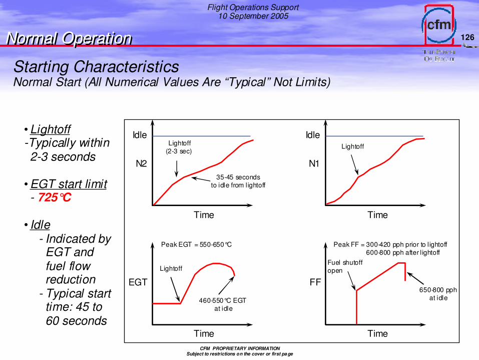
Starting CharacteristicsNormal Start (All Numerical Values Are “Typical” Not Limits)
• Lightoff-Typically within 2-3 seconds
• EGT start limit- 725°C
• Idle- Indicated by EGT and fuel flow reduction
- Typical start time: 45 to 60 seconds
Idle
N2
Time
Lightoff(2-3 sec)
35-45 secondsto idle from lightoff
Idle
N1
Time
Lightoff
EGT
Time
Lightoff
460-550°C EGTat idle
FF
Time
Fuel shutoffopen
650-800 pphat idle
Peak EGT = 550-650°C Peak FF = 300-420 pph prior to l ightoff600-800 pph after l ightoff
Normal OperationNormal Operation
127
Flight Operations Support10 September 2005
CFM PROPRIETARY INFORMATIONSubject to restrictions on the cover or first pa ge
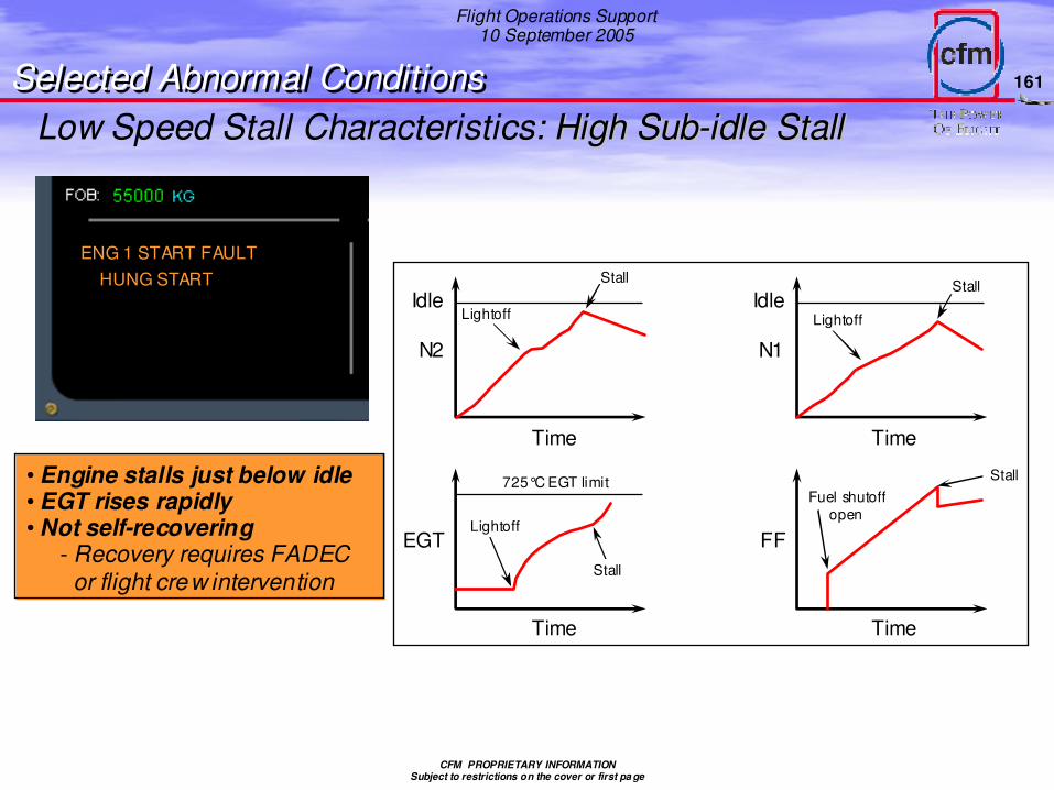
Low Speed Stall Characteristics
• Engine speed stagnates immediately after lightoff
• EGT rises rapidly
• Not self-recovering- Recovery requires FADEC or flight
crew intervention
Idle
N2
Time
LightoffIdle
N1
Time
Lightoff
EGT
Time
Lightoff
EGT continuesto rise
FF
Time
Fuel shutoffopen
N1 10% i n stallN2 40% i n stall
725°C EGT li mit
Idle
N2
Time
LightoffIdle
N1
Time
Lightoff
EGT
Time
Lightoff
725°C EGT limit
FF
Time
Fuel shutoffopen
Stall
Stall
Stall
Stall
High SubHigh Sub--idle Stallidle Stall
• Engine stalls just below idle
• EGT rises rapidly
• Not self-recovering- Recovery requires FADEC or flight crew
intervention
Lightoff Stall
Normal OperationNormal Operation
Start Stall Results (LPT 1)
128
Flight Operations Support10 September 2005
CFM PROPRIETARY INFORMATIONSubject to restrictions on the cover or first pa ge
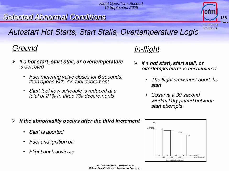
Autostart Failure to Lightoff Logic
Ground
� Lightoff detected when EGT increases 55°C above initial EGT
� If no lightoff within 15 seconds (20 seconds cold engine)
• Fuel and ignition turned off
• Dry-motored for 30 seconds
In-flight
� If no lightoff within 30 seconds
• Flight crew must turn fuel off
• Observe a 30 second windmill/dry motor period between start attempts
CFM PROPRIETARY INFORMATIONSubject to restrictions on the cover or first pa ge
Start
�Starter air pressure
• 25 psi desirable (start valve open)
• Warmer, slower starts with lower pressure
Note: the practical minimumstarter air pressure is that required to motor the engine to 22% N2 for auto start (programmed fuel on speed) or 20% N2 for manual start (minimum N2 for fuel on)
�Ignition selection is automatic
• Autostart: FADEC alternates A and B igniters on every other start
• Manual start: both igniters are used
�Fan rotation
• No restriction on opposite fan rotation (tailwind)
- Initial N1 indication slower with a tailwind
• If no N1 rotation detected by ~51% N2, an ECAM start fault message (“No N1”) is provided to crew
- Start must be aborted
�Tailwinds
• Starts demonstrated with 53 knot tailwind
• For CFM56-5A and –5B high tailwinds do not present a problem for start
�Expect warmer starts with high residual EGT
�Crosswinds
• No significant impact on start characteristics
Normal OperationNormal Operation
131
Flight Operations Support10 September 2005
CFM PROPRIETARY INFORMATIONSubject to restrictions on the cover or first pa ge6837H 0103A
Start up procedure
� Faster/colder ground starts on the SAC Engine
� Average start up time SAC 30 sDAC 1 mn
� SAC Cross bleed start procedure with the DAC engine(The operational case is when you start first the DAC engine, then the SAC engine)
Thrust has to be increased at 30% N1 on the DAC engine before lauching the start on the SAC, otherwise you could stay at idle or even have face a roll back on the DAC engine and not be able to start the SAC.
Ground Idle
• Higher EGT & higher fuel flow (25% at idle )can be noticed on the DAC engine.
• Lower N1 and Higher N2 at ground idle and Lower N1 and N2 at min idle in flight on the SAC Engine
• Depending on engine age &/or type &/or bleed supply, the range of EGTdifference can reach, basically, from 30°– 40°to 200°-250°C ** on the DAC engine.
• Quicker acceleration in N1 speed range from idle to 50% N1 on the SAC Engine
Start SAC/DAC intermix
Normal OperationNormal Operation
132
Flight Operations Support10 September 2005
CFM PROPRIETARY INFORMATIONSubject to restrictions on the cover or first pa ge
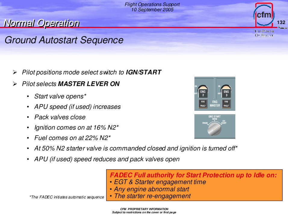
� Pilot positions mode select switch to IGN/START
� Pilot selects MASTER LEVER ON
• Start valve opens*
• APU speed (if used) increases
• Pack valves close
• Ignition comes on at 16% N2*
• Fuel comes on at 22% N2*
• At 50% N2 starter valve is commanded closed and ignition is turned off*
• APU (if used) speed reduces and pack valves open
Ground Autostart Sequence
Normal OperationNormal Operation
*The FADEC initiates automatic sequence
FADEC Full authority for Start Protection up to Idle on:• EGT & Starter engagement time• Any engine abnormal start• The starter re-engagement
133
Flight Operations Support10 September 2005
CFM PROPRIETARY INFORMATIONSubject to restrictions on the cover or first pa ge
Ground Manual Start Sequence
� Pilot selects mode selector switch to IGN/START
� Pilot depresses MANUAL START PB
• Start valve opens (25 psi desirable)
• APU speed increases
• Pack valve close
� Pilot selects MASTER SWITCH ON at 22% N2 or maximum achievable N2 (minimum 20% N2)
• Dual ignition and fuel flow
• At 50% N2 starter valve is commanded closed and ignition is turned off
Start protection during Ground Manual StartFADEC shall provide faults to FWC
LIMITED AUTHORITY TO ABORT THE STARTING SEQUENCE ONLY FOR EGTLIMITED AUTHORITY TO ABORT THE STARTING SEQUENCE ONLY FOR EGT
Normal OperationNormal Operation
134
Flight Operations Support10 September 2005
CFM PROPRIETARY INFORMATIONSubject to restrictions on the cover or first pa ge
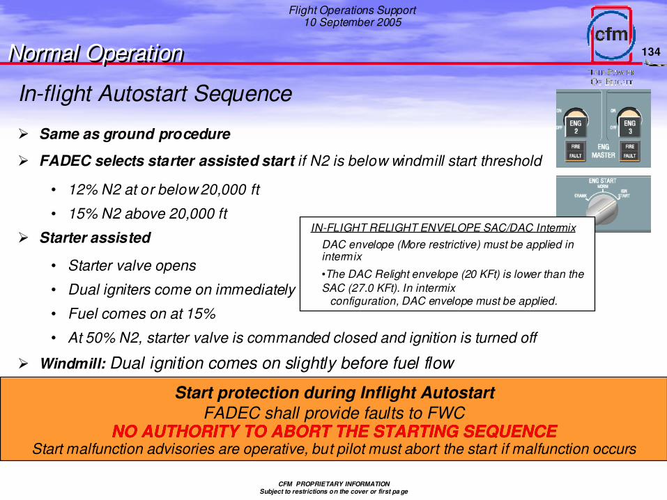
In-flight Autostart Sequence
� Same as ground procedure
� FADEC selects starter assisted start if N2 is below windmill start threshold
• 12% N2 at or below 20,000 ft
• 15% N2 above 20,000 ft
� Starter assisted
• Starter valve opens
• Dual igniters come on immediately
• Fuel comes on at 15%
• At 50% N2, starter valve is commanded closed and ignition is turned off
� Windmill: Dual ignition comes on slightly before fuel flow
Normal OperationNormal Operation
Start protection during Inflight AutostartFADEC shall provide faults to FWC
NO AUTHORITY TO ABORT THE STARTING SEQUENCENO AUTHORITY TO ABORT THE STARTING SEQUENCEStart malfunction advisories are operative, but pilot must abort the start if malfunction occurs
IN-FLIGHT RELIGHT ENVELOPE SAC/DAC IntermixDAC envelope (More restrictive) must be applied in intermix
•The DAC Relight envelope (20 KFt) is lower than the SAC (27.0 KFt). In intermix
configuration, DAC envelope must be applied.
135
Flight Operations Support10 September 2005
CFM PROPRIETARY INFORMATIONSubject to restrictions on the cover or first pa ge
In-flight Manual Start Sequence
�In the manual mode a starter assisted start is commanded through FADEC
�Pilot positions mode select switch to IGN/START
�Pilot depresses MANUAL START PB
�Pilot selects MASTER SWITCH ON at 15% N2 or maximumachievable N2
• Dual ignition and fuel flow
• At 50% N2 starter valve is commanded closed and ignition is turned off
• APU speed decreases and pack valves open (30 second delay)
Normal OperationNormal Operation
Start protection during Inflight Manual StartFADEC shall provide faults to FWC
NO AUTHORITY TO ABORT THE STARTING SEQUENCENO AUTHORITY TO ABORT THE STARTING SEQUENCEStart malfunction advisories are operative, but pilot must abort the start if malfunction occurs
136
Flight Operations Support10 September 2005
CFM PROPRIETARY INFORMATIONSubject to restrictions on the cover or first pa ge
� One Engines Taxi Out (Not recommended)
• 2 minutes minimum recommended before apply TakeOff thrust setting
• Crews have to consider no fire protection available from ground staff when starting the other engine away from the ramp.
• If mechanical problems occur during start up, departure time might be delayed due to a gate return.
• After frequent occurrences, possible increase of deterioration level versus the engine running first.
Warm up impact on cold engineWarm up impact on cold engine
* ref equal to TakeOff EGT with a 2 min warm up
CFM REP 05/09/00 based on PSE information
ref -15°C
ref -14°C
ref -12°C
ref -9°C
ref -4°Cref *EGT (°C)
2520151052Idle time (min)
Engines Estimated idle time impact on TakeOff EGTMargin
� Warm up 2 min mini prior to takeoffA cold engine is defined by shut-down of more than 6 hours. A 2 minutes minimum warm- up is recommended in the FCOM but CFMexperience shows that warm-up times between 10 and 15 minutes consistently reduces the takeoff EGT.
Taxi
Normal OperationNormal Operation
137
Flight Operations Support10 September 2005
CFM PROPRIETARY INFORMATIONSubject to restrictions on the cover or first pa ge
Taxi
Not sensitive to ambient conditions
• EGT unaffected by crosswinds may be slightly higher with tailwinds
• Constant idle thrust: N2 varies with OAT/PA to maintain constant thrust level
Minimize breakaway thrust
• Vortices is common cause of FOD ingestion on ground
• 10 knots headwind/Airspeed will destroy vortices formed up to 40% N1
10 knots
airspeed/headwind will destroy vortices formed up to 40% N1
30 knots
airspeed will destroy vortices formed at typical TakeOff thrust settings
Normal OperationNormal Operation
138
Flight Operations Support10 September 2005
CFM PROPRIETARY INFORMATIONSubject to restrictions on the cover or first pa ge
High FOD Potential Areas
• Desert Airports• Coastal Airports• Airports with: Construction activit, Deterioratedrunways/ramps/taxiways, Narrow runways/taxiways, Ramps/taxiways sanded for winter operation, Plowedsnow/sand beside runways/taxiways
Engine Vortices
• Strength increases at high thrust, low airspeed• High exposure
- Thrust advance for breakaway from stop- Thrust advance for TakeOff- Reverse Thrust at low airspeed- 180° turn on runway- Power assurance runs
• Destroyed by Airspeed and/or Headwind
Engine Vorticesis a common cause
of ingestion on ground
Taxi
Normal OperationNormal Operation
139
Flight Operations Support10 September 2005
CFM PROPRIETARY INFORMATIONSubject to restrictions on the cover or first pa ge
FOD (Recommendations)
• Avoid engine overhang of unpreparedsurface
• Minimize- breakaway and taxi thrust (Less than 40% N1, if possible)- Thrust assist from outboard enginein 180° turn
• Rolling TakeOff, if possible
• Reverse thrust- During taxi only on emergency- Minimize on contaminated runway
10 knots
airspeed/headwind will
destroy vortices formed up
to 40% N1
30 knots
airspeed will destroy
vortices formed at typical
TakeOff thrust settings
Taxi
Normal OperationNormal Operation
140
Flight Operations Support10 September 2005
CFM PROPRIETARY INFORMATIONSubject to restrictions on the cover or first pa ge
Taxi
Normal OperationNormal Operation
� Reverse thrust during taxi only in emergency
� Oil pressure varies with N2
• Minimum 13 psi (required ENG SHUT DOWN), May be full scale for cold soaked engine. less than 13 PSID is permissible for maximum of 10 seconds during “Negative G” operation
� Oil temperature
• No minimum
• Rise must be noted prior to takeoff
• Maximum 140°C continuous, 155°C for 15 minutes
� Oil quantity:
Gulping effect
Flight Phase D eviation From Pre-Start Quantity
Ground idl e 4 quarts (20%)
Takeoff 6 quarts (30%)
Climb, cruise, descent 4-5 quarts (20%-25%)
After l anding 4 quarts ( 20%)
Shutdown 0 quarts* (0%)Note: These values ar e not li mits . . . infor mation only
CFM56-5B Oil Pressure
300
100
90
80
70
60
50
40
30
20
10
050 60 70 80 90 100 1050
PSID
Cold start by-pass valve opens at 305 psid(2101 kPa diff)
Normal oper atingOil pressur e range
3
2
1
Core engine speed (N2) percent
Minim um acceptable pr essur e at minimum idle (13 psid) (76 kPa diff.)Less than minimum oil press ure requies engine shutdown
•Operation in areas 1 and 3 requires monitoring of oil pressure, temperature and quantity
•Operation area 1 requires maintenance action prior to next flight
141
Flight Operations Support10 September 2005
CFM PROPRIETARY INFORMATIONSubject to restrictions on the cover or first pa ge
Ground Operation in Icing Conditions� ANTI-ICE ON
• Anti-ices inlet lip
� During extended operation (more than 30 minutes):
• Accelerates engines to 70% N1 and hold for 30 seconds (or to an N1 and dwell time as high as practical, considering airport surface conditions and congestion)
- Allows immediate shedding of fan blade and spinner ice
- De-ices stationary vanes with combination of shed ice impact, pressure increase and temperature rise
Normal OperationNormal Operation
100
90
80
70
60
50
40
30
20
10
0
10
9
8
7
6
5
4
3
2
1
00 20 40 60 80 100 120 140 160 180
%N1 Fan vibes(units)
Time (seconds)
Ice shedpoint
• Perform this procedure every 30 minutes and just prior to or in conjunction with the takeoff procedure, with particular attention to engine parameters prior to final advance to takeoff thrust
* Note: In addition to the above when in freezing rain, drizzle or fog, heavy snow ice shedding may be enhanced by additional runups at intervals not to exceed ten minutes.
142
Flight Operations Support10 September 2005
CFM PROPRIETARY INFORMATIONSubject to restrictions on the cover or first pa ge
Takeoff
� N1 (fan speed) vs EPR used as power management parameter
• N1 directly related to fan thrust (80% of total) and to core thrust
• N1/thrust relationship insensitive to engine deterioration
• Less complex
• More reliable
Normal OperationNormal Operation
� Ignition
• Requirement specified by aircraft manufacturer
• Engine certification tests completed without the use of ignition
� Bleeds
• ON/OFF depending on company policy/performance requirements
• Effect on engine parameters
143
Flight Operations Support10 September 2005
CFM PROPRIETARY INFORMATIONSubject to restrictions on the cover or first pa ge
TAKEOFF PROCEDURE
• In consequence of the DAC spool up time lag (up to 5 seconds), the rolling takeoff procedure is not recommended.
• Apply Static T/O
1. Idle to 50% N1 on both engines
2. Release brakes when the 50% N1 is stabilized on both engines.
3. Both engines N1 to takeoff thrust.
Other standard operating procedures for takeoff apply
Flight Crews must be aware of the intermix Flight Crews must be aware of the intermix configuration and its operationconfiguration and its operation
TakeOff SAC/DAC intermix
Normal OperationNormal Operation
144
Flight Operations Support10 September 2005
CFM PROPRIETARY INFORMATIONSubject to restrictions on the cover or first pa ge
Full Thrust Take Off
EGT OAT
Thrust
Effect of Bleeds on EGT
Ble eds OFF
CP
Given OAT
Bleeds ON
Ble eds OFFBleeds ON
Eng Bleeds effect at TakeoffAt full take off power, there is a thrust decrement when setting Eng Bleeds Off to Bleeds On when EGT remain the same. Only MTOW is impacted, higher with Bleeds Off than Bleeds On.
Normal OperationNormal Operation
At reduced take off thrust, this is the same logic that full thrust. But as the TOW (Take Off Weight) is not maximum, in order to recover the same level of thrust Bleeds Off than Bleeds On, reduced thrust need to be increase, so EGT will decrease .
Reduced Thrust Take Off
EGT OAT
Thrust
Ble eds OFF
Effect of Bleeds on EGT
Ble eds OFF
CP
Given OAT
Bleeds ON
Bleeds ON
RedcuedRedcued thrustthrust TakeTake Off Off withwith engineengine bleedsbleeds OFF OFF increaseincrease engineengine livelive
145
Flight Operations Support10 September 2005
CFM PROPRIETARY INFORMATIONSubject to restrictions on the cover or first pa ge
Takeoff S.O.P.
� Before Takeoff :
APU BLEED ON or PACKS OFF ?
- PACKS ON (with APU bleed ON ) will increase passenger comfort.
- However, this leads to a higher APU use (i.e. increased APU maintenance costs).
Bleeds effectNormal OperationNormal Operation
146
Flight Operations Support10 September 2005
CFM PROPRIETARY INFORMATIONSubject to restrictions on the cover or first pa ge
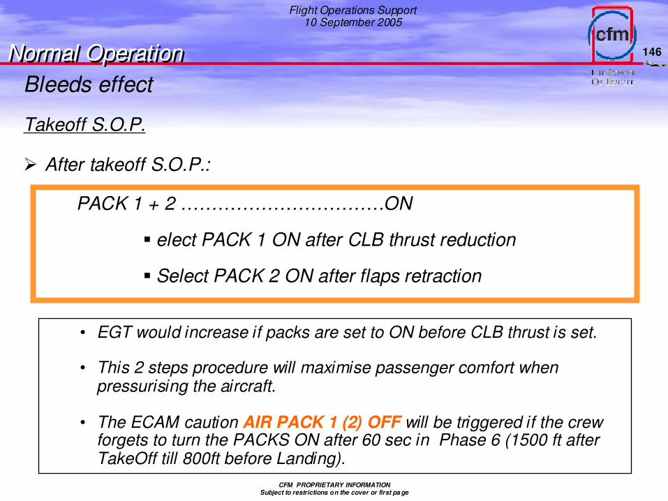
Takeoff S.O.P.
� After takeoff S.O.P.:
• EGT would increase if packs are set to ON before CLB thrust is set.
• This 2 steps procedure will maximise passenger comfort when pressurising the aircraft.
• The ECAM caution AIR PACK 1 (2) OFFAIR PACK 1 (2) OFF will be triggered if the crew forgets to turn the PACKS ON after 60 sec in Phase 6 (1500 ft after TakeOff till 800ft before Landing).
PACK 1 + 2 ……………………………ON
elect PACK 1 ON after CLB thrust reduction
Select PACK 2 ON after flaps retraction
Bleeds effectNormal OperationNormal Operation
147
Flight Operations Support10 September 2005
CFM PROPRIETARY INFORMATIONSubject to restrictions on the cover or first pa ge
� The thrust decrement is frozen by the FADEC when:
• The aircraft is on the ground
• Thrust levers at or above MCT/FLX
• The configuration is latched in flight until the thrust levers are set to CL
Bleed Failure at T/O
In case of a failure, the EGT may increase but the takeoff thrusIn case of a failure, the EGT may increase but the takeoff thrust remains.t remains.
� The thrust decrement is frozen by the FADEC during the takeoff. This avoids:
• Thrust fluctuations in case of an intermittent bleed failure.
• Thrust loss in case of a bleed failure (I.e. APU auto shutdown, with APU BLEED ON).
Normal OperationNormal Operation
150
Flight Operations Support10 September 2005
CFM PROPRIETARY INFORMATIONSubject to restrictions on the cover or first pa ge
� Bleed selection for takeoff has an impact on the takeoff performance.
� PACKS OFF or APU BLEED ON can be used:
• to improve performance when TOGA is used
• to reduce EGT when FLEX thrust is used:
- This will increase the engine’s life and decrease Maintenance costs
- This will help prevent EGT exceedances on engines with reduced EGT margins.
� Zone Controller and FADEC protection logics ensure a safe takeoff in case of abnormal bleed :
CFM PROPRIETARY INFORMATIONSubject to restrictions on the cover or first pa ge
� From an engine standpoint, rolling takeoff is preferred
• Less FOD potential on contaminated runways
• Inlet vortex likely if takeoff N1 set below 30 KIAS
• Less potential for engine instability or stall during crosswind/tailwind conditions
� N1 thrust management
• Engine control computes command N1 for max or reduced thrust
• Throttle “stand up” prior to full thrust (minimizes uneven acceleration)
• Pilot sets throttle for full thrust or reduced thrust
• Aircraft/engine controls maintain N1 at command value
Takeoff
Normal OperationNormal Operation
152
Flight Operations Support10 September 2005
CFM PROPRIETARY INFORMATIONSubject to restrictions on the cover or first pa ge
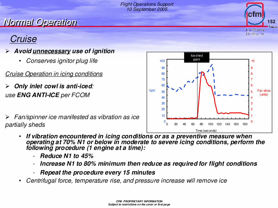
Cruise� Avoid unnecessary use of ignition
• Conserves ignitor plug life
Normal OperationNormal Operation
Cruise Operation in icing conditions
� Only inlet cowl is anti-iced:use ENG ANTI-ICE per FCOM
100
90
80
70
60
50
40
30
20
10
0
10
9
8
7
6
5
4
3
2
1
00 20 40 60 80 100 120 140 160 180
%N1 Fan vibes(units)
Time (seconds)
Ice shedpoint
� Fan/spinner ice manifested as vibration as ice partially sheds
• If vibration encountered in icing conditions or as a preventive measure when operating at 70% N1 or below in moderate to severe icing conditions, perform the following procedure (1 engine at a time):
- Reduce N1 to 45%- Increase N1 to 80% minimum then reduce as required for flight conditions- Repeat the procedure every 15 minutes
• Centrifugal force, temperature rise, and pressure increase will remove ice
153
Flight Operations Support10 September 2005
CFM PROPRIETARY INFORMATIONSubject to restrictions on the cover or first pa ge
• Minimize reverse thrust use on contaminated runways
• Reversers most effective at higher airspeed
• Modulate reverse if full thrust not needed
- Less thermal stress and mechanical loads
- Reduced FOD
• Reduce reverse thrust at 70 KIAS
• Reverse thrust is more effective at high speed
- Use high reverse thrust early, if necessary
• Start reducing reverse thrust per aircraft operations manual
- For FOD conditions, at 80 kias, if practical
- Most installations are certified for full thrust use to 60 kias (without engine instability) but re-ingestion of exhaust gases/debris may occur at full reverse thrust below 80 kias
• Select forward thrust at taxi speed and before clearing runway
Descent
Smooth power reduction
In Approach Idle mode the DAC logic mode switches to the 20/2*5 when the flaps/slats are extended
Idle most economical
Engine control maintains appropriate idle speed
Engine control maintains mini N1 required for operation in icing or rain/hail conditions
Landing/ReversingNormal OperationNormal Operation
Effect of N1 and Airspeed onNet Reverse Thrust
154
Flight Operations Support10 September 2005
CFM PROPRIETARY INFORMATIONSubject to restrictions on the cover or first pa ge
Shutdown
� 3 minutes cooldown after coming out of reverse
• Includes taxi
� One Engine Taxi In ?.. Operators have to keep in mind some specifics.
• On well known airports to take benefit of this procedure by anticipating maneuvers
• Caution to avoid jet blast and FOD
• More thrust for breakaway and 180°turn
• Turns on the operating engine may not be possible at high GW
• Fuel saving with one-engine taxi: 12 minutes of one-engine taxi on A320 burns 92 kg of fuel versus 138 kg with 2 engines. Saving is 46 kg.
� Cool down not required for emergency shutdown
Normal OperationNormal Operation
155
Flight Operations Support10 September 2005
CFM PROPRIETARY INFORMATIONSubject to restrictions on the cover or first pa ge
Flight Ops Support
Technical FeaturesTechnical Features
Normal Operating ConsiderationsFlight phases, ops recommendations
Normal Operating ConsiderationsFlight phases, ops recommendations
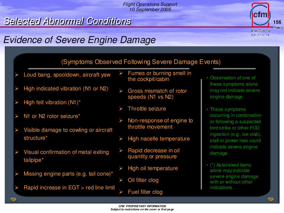
(Symptoms Observed Following Severe Damage Events)
Evidence of Severe Engine Damage
� Loud bang, spooldown, aircraft yaw
� High indicated vibration (N1 or N2)
� High felt vibration (N1)*
� N1 or N2 rotor seizure*
� Visible damage to cowling or aircraft structure*
� Visual confirmation of metal exiting tailpipe*
� Missing engine parts (e.g. tail cone)*
� Rapid increase in EGT > red line limit
� Fumes or burning smell in the cockpit/cabin
� Gross mismatch of rotor speeds (N1 vs N2)
� Throttle seizure
� Non-response of engine to throttle movement
� High nacelle temperature
� Rapid decrease in oil quantity or pressure
� High oil temperature
� Oil filter clog
� Fuel filter clog
• Observation of one of these symptoms alone may not indicate severe engine damage
• These symptoms occurring in combination or following a suspected bird strike or other FOD ingestion (e.g., ice slab), stall or power loss could indicate severe engine damage
• (*) Asterisked items alone may indicate severe engine damage with or without other indications
157
Flight Operations Support10 September 2005
CFM PROPRIETARY INFORMATIONSubject to restrictions on the cover or first pa ge
Autostart Failure to Lightoff Logic
Ground
� Lightoff detected when EGT increases 55°C above initial EGT
� If no lightoff within 15 seconds (20 seconds cold engine)
• Fuel and ignition turned off
• Dry-motored for 30 seconds
In-flight
� If no lightoff within 30 seconds
• Flight crew must turn fuel off
• Observe a 30 second windmill/dry motor period between start attempts


![IA V16-4411 Lxx EN neu.ppt [Kompatibilitätsmodus] GmbH Datasheet V16.pdf1450 RPM 1250 RPM 1100 RPM 900 RPM 750 RPM 5 15 25 50 100 150 200 250 300 350 Discharge Pressure [bara] Power](https://static.documents.pub/doc/80x56/60ab012c0916f1699d2afa18/ia-v16-4411-lxx-en-neuppt-kompatibilittsmodus-gmbh-datasheet-v16pdf-1450-rpm.jpg)


