IMPORTANT File in your maintenance records 5050 Stretcher Chair MAINTENANCE MANUAL For stretchers with serial numbers of 9711034601 and above For Parts or Technical Assistance: 1–800–327–0770
Transcript
IMPORTANTFile in yourmaintenancerecords
5050 Stretcher Chair
MAINTENANCE MANUALFor stretchers with serial numbers of 9711034601 and above
This manual is designed to assist you with the maintenance of the model 5050 Stretcher Chair. Read it thor-oughly before using the equipment or beginning any maintenance on it.
SPECIFICATIONS
Maximum Weight Capacity 400 pounds
Overall Stretcher Length/Width 76”/30”
Patient Surface Length/Width (Mattress) 74”/24”
Minimum/Maximum Stretcher Height (Floor to Litter Surface) 22”/33.5”
The words WARNING, CAUTION and NOTE carry special meanings and should be carefully reviewed.
WARNINGThe personal safety of the patient or user may be involved. Disregarding this information could result in injuryto the patient or user.
CAUTION
These instructions point out special procedures or precautions that must be followed to avoid damaging theequipment.
NOTEThis provides special information to make maintenance easier or important instructions clearer.
WARNING
Always apply the caster brakes when a patient is getting on or off the Stretcher Chair. Push on the StretcherChair to ensure the brakes are securely locked. Always engage the brakes unless the Stretcher Chair is beingmoved. Injury could result if the Stretcher Chair moves while a patient is getting on or off the Stretcher Chair.
4
Preventative Maintenance
CHECKLIST
All fasteners secure (reference all assembly prints)
Siderails move and latch properly – securing pins and screws are intact
Transfer surface (optional equipment) intact and working properly
Engage brake pedal and push on the stretcher to ensure all casters lock securely
All casters secure and swiveling properly
Steer function working properly
Fowler/leg articulation operating properly – adjust as necessary
Hand wash all surfaces of the stretcher with warm water and mild detergent. Dry thoroughly. DO NOTSTEAM CLEAN, PRESSURE WASH, HOSE OFF OR ULTRASONICALLY CLEAN. Using these methodsof cleaning is not recommended and may void this product’s warranty.Clean Velcro AFTER EACH USE. Saturate Velcro with disinfectant and allow disinfectant to evaporate. (Ap-propriate disinfectant for nylon Velcro should be determined by the hospital.)
In general, when used in those concentrations recommended by the manufacturer, either phenolic type orquaternary type disinfectants can be used with Staph–Chek fabrics. Iodophor type disinfectants are not rec-ommended for use on Staph–Chek fabrics because staining may result. The following products have beentested by the Herculite Laboratory and have been found not to have a harmful effect on Staph–Chek fabricsWHEN USED IN ACCORDANCE WITH MANUFACTURERS RECOMMENDED DILUTION.*
Quaternary Germicidal Disinfectants, used as directed, and/or Chlorine Bleach products, typically 5.25% So-dium Hypochlorite in dilutions ranging between 1 part bleach to 100 parts water, and 2 parts bleachto 100 parts water are not considered mild detergents. These products are corrosive in nature andmay cause damage to your stretcher if used improperly. If these types of products are used to cleanStryker patient handling equipment, measures must be taken to insure the stretchers are rinsed with cleanwater and thoroughly dried following cleaning. Failure to properly rinse and dry the stretchers will leave a cor-rosive residue on the surface of the stretcher, possibly causing premature corrosion of critical components.
NOTEFailure to follow the above directions when using these types of cleaners may void this product’s warranty.
REMOVAL OF IODINE COMPOUNDS
This solution may be used to remove iodine stains from mattress cover and foam footrest pad surfaces.
1. Use a solution of 1–2 tablespoons Sodium Thiosulfate in a pint of warm water to clean the stained area.Clean as soon as possible after staining occurs. If stains are not immediately removed, allow solution tosoak or stand on the surface.
2. Rinse surfaces which have been exposed to the solution in clear water before returning bed to service.
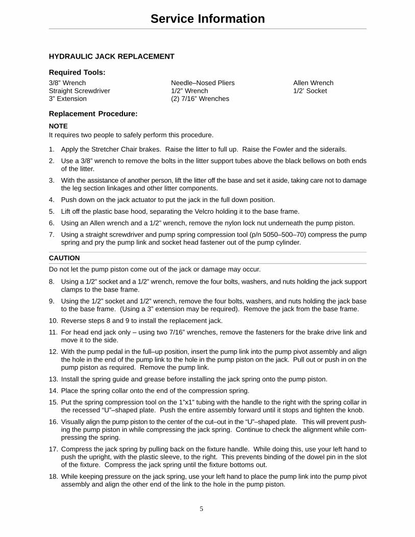
NOTEIt requires two people to safely perform this procedure.
1. Apply the Stretcher Chair brakes. Raise the litter to full up. Raise the Fowler and the siderails.
2. Use a 3/8” wrench to remove the bolts in the litter support tubes above the black bellows on both endsof the litter.
3. With the assistance of another person, lift the litter off the base and set it aside, taking care not to damagethe leg section linkages and other litter components.
4. Push down on the jack actuator to put the jack in the full down position.
5. Lift off the plastic base hood, separating the Velcro holding it to the base frame.
6. Using an Allen wrench and a 1/2” wrench, remove the nylon lock nut underneath the pump piston.
7. Using a straight screwdriver and pump spring compression tool (p/n 5050–500–70) compress the pumpspring and pry the pump link and socket head fastener out of the pump cylinder.
CAUTION
Do not let the pump piston come out of the jack or damage may occur.
8. Using a 1/2” socket and a 1/2” wrench, remove the four bolts, washers, and nuts holding the jack supportclamps to the base frame.
9. Using the 1/2” socket and 1/2” wrench, remove the four bolts, washers, and nuts holding the jack baseto the base frame. (Using a 3” extension may be required). Remove the jack from the base frame.
10. Reverse steps 8 and 9 to install the replacement jack.
11. For head end jack only – using two 7/16” wrenches, remove the fasteners for the brake drive link andmove it to the side.
12. With the pump pedal in the full–up position, insert the pump link into the pump pivot assembly and alignthe hole in the end of the pump link to the hole in the pump piston on the jack. Pull out or push in on thepump piston as required. Remove the pump link.
13. Install the spring guide and grease before installing the jack spring onto the pump piston.
14. Place the spring collar onto the end of the compression spring.
15. Put the spring compression tool on the 1”x1” tubing with the handle to the right with the spring collar inthe recessed “U”–shaped plate. Push the entire assembly forward until it stops and tighten the knob.
16. Visually align the pump piston to the center of the cut–out in the “U”–shaped plate. This will prevent push-ing the pump piston in while compressing the jack spring. Continue to check the alignment while com-pressing the spring.
17. Compress the jack spring by pulling back on the fixture handle. While doing this, use your left hand topush the upright, with the plastic sleeve, to the right. This prevents binding of the dowel pin in the slotof the fixture. Compress the jack spring until the fixture bottoms out.
18. While keeping pressure on the jack spring, use your left hand to place the pump link into the pump pivotassembly and align the other end of the link to the hole in the pump piston.
6
Service Information
HYDRAULIC JACK REPLACEMENT (CONTINUED)
19. With pressure still on the jack spring, install the socket head cap screw through both the pump link andthe pump piston.
20. Partially thread the locking nut for the socket head cap screw before taking the jack fixture off the 1”x1”tube.
21. Tighten the locking nut for the socket head cap screw.
22. Pump the jack fully up and lower to ensure proper operation.
23. Reinstall the base hood, securing it to the Velcro.
24. With the assistance of another person, place the litter back on the base.
25. Use a 3/8” wrench to install the bolts in the litter support tubes above the black bellows on both ends ofthe litter.
26. Pump the litter fully up and down to verify proper operation before returning the Stretcher Chair to service.
JACK PUMP PISTON REPLACEMENT
Replacement pump piston part # – 715–100–325 Jack tool part # – 5050–500–70
NOTEIt requires two people to safely perform this procedure.
1. Apply the Stretcher Chair brakes. Raise the litter to full up. Raise the Fowler and the siderails.
2. Use a 3/8” wrench to remove the bolts in the litter support tubes above the black bellows on both endsof the litter.
3. With the assistance of another person, lift the litter off the base and set it aside, taking care not to damagethe leg section linkages and other litter components.
4. Push down on the jack actuator to put the jack in the full down position.
5. Lift off the plastic base hood, separating the Velcro holding it to the base frame.
6. Using an Allen wrench, and a 1/2” wrench, remove the nylon lock nut underneath the pump piston.
7. Using a straight screwdriver and pump spring compression tool (p/n 5050–500–70), compress the pumpspring and pry the pump link and socket head fastener out of the pump cylinder.
8. Remove the jack spring.
9. Using needle–nosed pliers, remove the spring holder.
10. Using a 7/8” wrench, remove the pump piston assembly and the bottom seal and discard the seal. Theremay be some slight hydraulic fluid leakage.
11. Install the replacement seal into the jack base.
12. Install the replacement pump piston assembly and tighten fully with a 7/8” wrench.
13. For head end jack only – using two 7/16” wrenches, remove the fasteners for the brake drive link andmove it to the side.
7
Service Information
JACK PUMP PISTON REPLACEMENT (CONTINUED)
14. With the pump pedal in the full–up position, insert the pump link into the pump pivot assembly and alignthe hole in the end of the pump link to the hole in the pump piston on the jack. Pull out or push in on thepump piston as required. Remove the pump link.
15. Install the spring guide and grease before installing the jack spring onto the pump piston.
16. Place the spring collar onto the end of the compression spring.
17. Install the spring compression tool onto the 1”x1” tubing with the handle to the right and capture the springcollar in the recessed “U”–shaped plate. Push the entire assembly forward until it stops and tighten theknob.
18. Visually align the pump piston to the center of the cut–out in the “U”–shaped plate. This will prevent push-ing the pump piston in while compressing the jack spring. Continue to check the alignment while com-pressing the spring.
19. Compress the jack spring by pulling back on the fixture handle. While doing this, use your left hand topush the upright, with the plastic sleeve, to the right. This prevents binding of the dowel pin in the slotof the fixture. Compress the jack spring until the fixture bottoms out.
20. While keeping pressure on the jack spring, use your left hand to place the pump link into the pump pivotassembly and align the other end of the link to the hole in the pump piston.
21. With pressure still on the jack spring, install the socket head cap screw through both the pump link andthe pump piston.
22. Partially thread the locking nut for the socket head cap screw before taking the jack fixture off the 1”x1”tube.
23. Tighten the locking nut for the socket head cap screw.
24. Pump the jack fully up and lower to ensure proper operation.
25. Reinstall the base hood, securing it to the Velcro.
26. With the assistance of another person, place the litter back on the base.
27. Use a 3/8” wrench to install the bolts in the litter support tubes above the black bellows on both ends ofthe litter.
28. Pump the litter fully up and lower to ensure proper operation before returning the Stretcher Chair to ser-vice.
8
Service Information
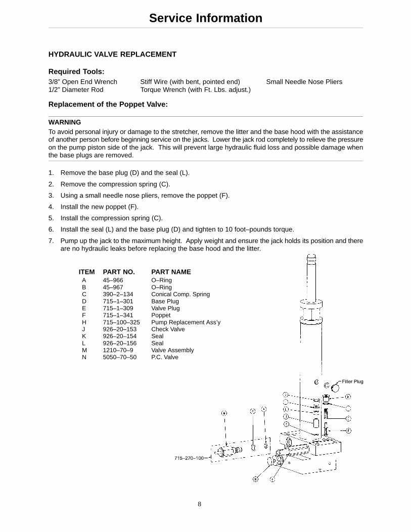
HYDRAULIC VALVE REPLACEMENT
Required Tools:3/8” Open End Wrench Stiff Wire (with bent, pointed end) Small Needle Nose Pliers1/2” Diameter Rod Torque Wrench (with Ft. Lbs. adjust.)
Replacement of the Poppet Valve:
WARNINGTo avoid personal injury or damage to the stretcher, remove the litter and the base hood with the assistanceof another person before beginning service on the jacks. Lower the jack rod completely to relieve the pressureon the pump piston side of the jack. This will prevent large hydraulic fluid loss and possible damage whenthe base plugs are removed.
1. Remove the base plug (D) and the seal (L).
2. Remove the compression spring (C).
3. Using a small needle nose pliers, remove the poppet (F).
4. Install the new poppet (F).
5. Install the compression spring (C).
6. Install the seal (L) and the base plug (D) and tighten to 10 foot–pounds torque.
7. Pump up the jack to the maximum height. Apply weight and ensure the jack holds its position and thereare no hydraulic leaks before replacing the base hood and the litter.
ITEM PART NO. PART NAME A 45–966 O–Ring B 45–967 O–Ring C 390–2–134 Conical Comp. Spring D 715–1–301 Base Plug E 715–1–309 Valve Plug F 715–1–341 Poppet H 715–100–325 Pump Replacement Ass’y J 926–20–153 Check Valve K 926–20–154 Seal L 926–20–156 Seal M 1210–70–9 Valve Assembly N 5050–70–50 P.C. Valve
9
Service Information
HYDRAULIC VALVE REPLACEMENT (CONTINUED)
Replacement of the Check Valve:
NOTEIt requires two people to safely perform this procedure.
WARNINGTo avoid personal injury or damage to the stretcher, always remove the litter and the base hood before begin-ning service on the jacks.
1. Using a 3/8” open end wrench, remove square head set screws from both the head end and the foot endjack support tubes. Remove the litter top and set it aside.
2. Lift off the plastic base hood, separating the Velcro holding it to the base frame.
3. Lower the jack to the full down position. The actuator must be manually lowered while the appropriaterelease pedal is depressed.
4. Remove the base plug (D) and the seal (L).
5. Remove the valve plug (E).
6. Using a stiff wire with a bent, pointed end, remove the check valve (J) and the seal (K).
7. Install the seal (K) flat to the bottom of its hole with a 1/2” diameter rod.
8. Install the new check valve (J) with the beveled end up (as shown in the illustration).
9. Install the valve plug (E) and tighten to 10 foot–pounds torque.
10. Install the seal (L) with the base plug (D) and tighten to 10 foot–pounds torque.
11. Pump up the jack to the maximum height. Apply weight and ensure the jack holds its position and thereare no hydraulic leaks before replacing the base hood and the litter.
CHECKING HYDRAULIC FLUID LEVEL
Required Tools:3/8 Open End Wrench 3/4 Open End Wrench
Procedure:1. Using a 3/8 open end wrench, remove square head set screws from both head and foot end jack support
tubes. Remove litter top, taking care not to damage the leg section linkages and other litter components.
2. Lift off the plastic base hood, separating the Velcro holding it to the base frame.
3. Be sure there are no hydraulic leaks. If there are, jack replacement will be necessary. Lower the jackto the full down position. Using a 3/4 open end wrench, slowly turn the fill plug located on the side of thereservoir counterclockwise to allow excess system pressure to vent. Remove the fill plug.
4. The hydraulic fluid should be visible at the bottom of the fill hole. If it is not, add Mobil Aero HFA hydraulicfluid (Stryker part number 2020–70–475) until the fluid is visible at the bottom of the fill hole. Replacethe fill plug.
CAUTION
Use of other types of oil may damage hydraulic units.
WARNINGTo avoid personal injury or damage to the stretcher, always remove the litter and the base hood before begin-ning service on the jacks. Lower the jack rod completely to relieve the pressure on the pump piston side ofthe jack.
Required Tools:
3/8” Wrench 13/16” Wrench
Replacement Procedure:
NOTEIt requires two people to safely perform this procedure.
1. Apply the Stretcher Chair brakes. Raise the litter to full up. Raise the Fowler and the siderails.
2. Use a 3/8” wrench to remove the bolts in the litter support tubes above the black bellows on both endsof the litter.
3. With the assistance of another person, lift the litter off the base and set it aside, taking care not to damagethe leg section linkages and other litter components.
4. Push down on the jack actuator to put the jack in the full down position.
5. Lift off the plastic base hood, separating the Velcro holding it to the base frame.
6. Using a 13/16” wrench, remove the adjustable P.C. valve (see page 8 for part identification).
7. Check for any contaminants in the valve as well as the jack base.
8. Install a new P.C. valve. Moisten the O–ring seal with a little hydraulic fluid to ensure a good seal.
9. Tighten the valve manually and then an additional 1/8–1/4 turn with 13/16” wrench. Do not over –tightenor damage may occur to the O–ring seal.
10. Pump up the jack to the maximum height and press the release pedal to lower it to check the jack’s opera-tion.
11. Check for any hydraulic fluid leaks before replacing the base hood and litter.
11
Service Information
JACK DESCENT RATE ADJUSTMENT
Required Tools:
Bungee Cords
Adjustment Procedure:
1. Pump the litter up to full height
2. Lift the base hood, separating the Velcro holding it to the base frame.
3. The adjustable descent valve is located on the base of the jack and has a blue knob on the end. To adjust,loosen the silver locking ring by turning it counterclockwise. Turning the blue knob clockwise will increasethe rate of litter descent. Turning it counterclockwise will decrease the rate of descent.
4. Adjust the valve so that the jack at the foot end of the Stretcher Chair will descend slightly faster thanthe jack at the head end.
5. Remove the bungee cords supporting the base hood and secure the hood to the base frame.
NOTEThe jack descent rate was preset at the factory to drop the foot end 3–7 seconds faster than the head. It isrecommended that the foot drops faster to avoid patient disorientation.
STEERLOCK SPRING REPLACEMENT
Required Tools:
3/32” Hex Allen Wrench 11/32” WrenchBungee Cords Pliers
Replacement Procedure:
1. Raise the litter to full–up.
2. Lift up the plastic base hood, separating the Velcro holding it to the base frame and, using the bungeecords, suspend it from the litter.
3. Using a 3/32” hex Allen wrench and a 11/32” wrench, remove the 8–32 fastener, washer and nut holdingthe steerlock arm onto the base.
4. Holding onto the extension spring, twist the steerlock arm back and forth to remove it from the spring.
5. Using pliers, remove the spring from the steerlock weldment over the caster and discard it.
6. Grease the end of the steerlock weldment and install the replacement extension spring onto it until thespring reaches the bend in the steerlock weldment arm.
7. Grease the end of the steerlock arm and, while holding the extension spring, insert the steerlock arm intothe spring until it reaches the bend in the steerlock arm (rotating the steerlock arm while pushing on itmay help).
8. Reconnect the steerlock arm to the base with the 8–32 fastener, washer, and nylon lock nut and tighten.
9. Actuate the brake steer pedal and ensure the steerlock latch engages into the notch in the locking caster.
10. Remove the bungee cords supporting the base hood and secure the hood to the base frame.
12
Service Information
BRAKE/STEER PEDAL REPLACEMENT
Required Tools:
Two (2) 7/16” Wrenches 3/16” Drive Pin Loctite 409 or EquivalentHammer 3/8” Box End Wrench Bungee Cords
Replacement Procedure:
NOTEIt may require two people to safely perform this procedure.
1. Apply the brakes, if possible, with the remaining good brake/steer pedal. If this is not possible, havesomeone assist you with the following: Using a large wrench or pry tool, push down on the brake bar(compressing the spring) and manually move the molded plastic brake cam over to the brake positionat both ends of the base.
2. Raise the litter to full up. Raise the Fowler and the siderails.
3. Suspend the base hood from the litter and out of the way with bungee cords. Or, for better access, re-move the litter by following the next 3 steps.
4. Using a 3/8” wrench, remove the bolt in the litter support tube above the black bellows on both ends.
5. With the assistance of another person, lift off the stretcher litter and set it aside, taking care not to damagethe leg section linkages, or other litter components.
6. Lift off the plastic base hood, separating the Velcro holding it to the base frame.
7. Using the 7/16” wrenches, remove the bolt, nut and washers holding the square brake drive link assemblyon the brake actuator on both sides of the base.
8. While lifting one end (head or foot) of the base, rotate the brake/steer pedal so its bottom is facing up.
9. Use a hammer and 3/16” drive pin to remove the groove pin (part number 26–261) from the plastic brake/steer pedal (part number 715–201–201). Be sure that you are driving the pin out from the bottom of thepedal towards the top of the pedal.
10. Once the groove pin has been removed, remove the brake/steer pedal from the brake rod (use of a ham-mer may be required).
11. Repeat step 8 so the brake actuators are upright.
12. Fit the replacement brake/steer pedal onto the brake rod.
13. Align the holes in the brake/steer pedal with the holes in the brake rod and use a hammer to install thereplacement groove pin. Drive the pin in from the top of the pedal until it is flush to the top of the pedal.
14. Reverse step 7 to reattach both brake drive link assemblies to the base (When the pedal is reconnectedit will already be in the brake position).
15. Actuate the brake/steer pedal to ensure the unit functions fully in brake, neutral and steer modes.
16. Reinstall the base hood, securing it to the Velcro.
17. With the assistance of another person, place the litter back on the base (if necessary).
18. Use a 3/8” wrench to install the bolts in the litter support tubes above the black bellows on both ends ofthe litter.
13
Service Information
SIDERAIL ADJUSTMENT
Required Tools:
3/16” Hex Allen Wrench Loctite 242
WARNINGProper siderail latching is necessary for patient and user safety. Check the siderails frequently to ensure bothsides latch securely in both the upright and down positions. In addition, check for proper lubrication of therelease handle and for secure dowel pins through the sides of the siderails.
If siderail will not latch in place:
1. Ensure the red knob is seated fully when released in either the upright or down position (down positionwill be slightly tucked under the litter). If it is not, use a 3/16” hex Allen wrench to remove the button headcap screw in the end of the red knob. Apply Loctite 242 to the end of the screw, replace it in the knob,and tighten fully.
If a release knob assembly needs replacing:
1. Use a 3/16” Allen wrench to remove the button head cap screw, washer and spring in the end of the redrelease knob.
2. Hold the siderail to keep it from swinging and pull off the release knob assembly.
3. Apply grease to the release knob shaft and inspect the locking pin holes to ensure they are not obstructed.
4. Install the replacement knob and push it all the way in so the siderail latches in the upright position.
5. Carefully pull the release knob back and put the siderail in the down position. Push the knob back in fullyand ensure it latches in the down position. If it does not, pull out on the knob and rotate it 180�. It shouldnow latch in both the upright and down positions.
6. Replace the compression spring and washer.
7. Apply Loctite 242 to the end of the screw and replace it in the end of the knob and tighten fully.
8. Check again to ensure the knob latches in place in both positions.
14
Service Information
SIDERAIL REPLACEMENT (TRANSFER/NON–TRANSFER)
Required Tools:
Hammer 1/4” Drive Pin 3/16” Hex Allen WrenchLoctite 242 Pliers
Replacement Procedure:
1. Apply the Stretcher Chair’s brakes. Raise the litter to full height and put the Fowler up.
2. Rotate the siderail to a horizontal position and support it.
3. With the siderail in the horizontal position, use a 1/4” drive pin and a hammer to drive out the pin holdingthe siderail.
4. While continuing to support the siderail from underneath (to prevent it from falling), pull back on the redrelease knob and remove the knob assembly with the latch pivot shaft.
5. Once the knob assembly and latch pivot shaft are removed, the entire siderail assembly will pull awayfrom the litter and off the pivot hub at the foot end of the midsection. Save the latch housing insert. Itwill be used for assembly of the replacement siderail.
6. Place the latch housing insert into the main tube of the replacement siderail and rotate it so the singlehole in the face of it is upright (pointing to the top of the replacement siderail). This orientation must bemaintained throughout assembly.
7. Place the replacement siderail on the pivot hub at the foot end of the midsection and swing it back intoplace in the upright position.
8. Using a 3/16” hex Allen wrench, remove the fastener from the end of the red release knob and disas-semble the washer, spring and latch pivot shaft.
9. Insert the latch pivot shaft through the hole in the litter frame and into the latch housing insert and orientit so all the holes in the siderail tube, latch housing insert, and the latch pivot shaft are aligned. Again,this alignment must be maintained. It may help to use the 1/4” drive pin to hold all three parts in alignment.Insert the pin from the outside of the siderail to the inside with the siderail in the upright position.
10. From below the siderail, remove the punch being used to maintain alignment, insert the dowel pin fromthe top of the siderail and drive it in using a hammer until it is flush with the top surface of the siderail.Use the punch to set the pin slightly deeper. The pin should be approximately the same depth on bothsides of the siderail but be sure not to drive it back out the other side.
11. With the siderail in the upright position, replace the red release knob over the shaft and into the positionlocking holes.
12. Ensure the siderail will lock in both the upright and down positions and that the down position locks thesiderail at a slight inward angle (not outward).
13. If this is not the case, rotate the knob 180� and check the positioning again.
14. Replace the compression spring and the steel washer inside the end of the red release knob . Apply Loc-tite 242 to the Allen head screw, install it into the end of the red release knob and tighten fully.
15
Service Information
DEPENDENT LEG SECTION RIGID LINK REPLACEMENT
Required Tools:
(2) 9/16” Wrenches 1/2” Wrench 3/16” Hex Allen Wrench
Replacement Procedure:
1. Pump the litter to full height, lower the Fowler so that stretcher chair is flat and apply brakes.
2. Using two 9/16” wrenches, remove the nylon lock nut, hex head bolt), and nylon washers at the foot endof the rigid connecting link.
3. Using a 1/2” wrench and a 3/16” hex Allen wrench, remove the nylon lock nut, bolt and washers at thehead end of the rigid connecting link and remove the link.
4. Reverse steps 2 & 3 to install the replacement rigid connecting link.
5. Actuate the Fowler up and down to make sure that the rigid connecting link allows the foot section to followsmoothly.
FOOT REST PAN REPLACEMENT (FOR STATIONARY OR ADJUSTABLE FOOT REST)
Required Tools:
5/32” Hex Allen Wrench 7/16” Wrench Velcro Strip
Replacement Procedure:
1. Pump the litter to full height, lower the Fowler so the Stretcher Chair is flat and apply the brakes.
2. Be sure the foot rest pan is in the flat, stored position and remove the foot rest pad.
3. Using a 5/32” hex Allen wrench and a 7/16” wrench, remove the nylon lock nut, bolt, and washers fromboth of the foot rest pivots, located underneath the foot section.
4. Lift up and remove the damaged foot rest pan and discard.
5. Install the replacement foot rest pan, lying it flat on the foot section of the litter with the L–brackets fromthe pan fitting down underneath the litter surface.
6. For stationary foot rest only – align the holes in the foot pan L–brackets with the round pivots on the footsection frame.
7. Reverse step 3 to install the necessary fasteners.
8. Replace foot rest pad and Velcro if necessary
9. Ensure the foot rest pan moves smoothly from the stored position to down and back.
16
Service Information
DEPENDENT LEG SECTION FRAME REPLACEMENT
Required Tools:
(2) 9/16” Wrenches 3/16” Hex Allen Wrench 1/2” Wrench
Replacement Procedure:
1. Pump the litter to full height, lower the Fowler so the Stretcher Chair is flat and apply brakes.
2. Remove the litter mattress and set aside.
3. Using two 9/16” wrenches, remove the nylon lock nuts, bolts and washers on both of the rigid connectinglinks at the foot end.
4. Using a 3/16” hex Allen wrench and a 1/2” wrench, remove the nylon lock nuts, bolts and washers forthe leg section frame pivot and remove the entire leg section frame.
5. Install the replacement leg section frame, reversing step 4 to reconnect the leg section pivots.
6. Reverse step 2 to reconnect the rigid connecting links to the leg section.
7. If the replacement leg section did not include a new foot rest pan, install the pan from the old leg sectionfollowing the foot rest pan replacement procedure on page 15.
8. Actuate the Fowler up and down to make sure the foot section follows smoothly.
9. Replace the litter mattress.
STATIONARY PUSH BAR REPLACEMENT
Required Tools:(2) 9/16” Wrenches 3/16” Hex Allen Wrench 1/2” Wrench3/32” Hex Allen Wrench
Replacement Procedure:
1. Apply the brakes, raise the litter to full height and raise the Fowler to 90�.
2. Using the 3/32” hex Allen wrench, remove the button head cap screws from the small plastic covers ateach end of the push bar. Remove the covers and set them aside.
3. Using the 3/16” hex Allen wrench and the 1/2” wrench, remove the button head screw, nylock nut, andwashers on both sides of the push bar. (After the second fastener is removed, the push bar will rotatedown and hang freely).
4. Using two 9/16” wrenches, remove the remaining 3/8” bolt, centerlock nut, and washers on both sidesof the push bar and remove the push bar.
5. Reverse steps 2–4 to install the replacement push bar and the covers.
17
Service Information
ADJUSTABLE PUSH BAR REPLACEMENT
Required Tools:
(2) 9/16” Wrenches (2) 1/8” Hex Allen Wrenches 3/32” Hex Allen Wrench
Replacement Procedure:
1. Apply the brakes, raise the litter to full height and raise the Fowler to 90�.
2. Use the 3/32” hex Allen wrench to remove the button head cap screws from the small plastic covers atthe ends of the left side of the push bar. Remove the covers and set them aside.
3. Use the two 9/16” wrenches to remove the centerlock nut from the left side of the adjustable push bar.
4. Use the two 1/8” hex Allen wrenches to remove the button head fasteners from the sides of the red pushbar release handle (both the wrenches must be used together to remove the fasteners). It is O.K. to leaveone of the fasteners attached to the position locking pin for the push bar – only one of the fasteners mustbe removed.
5. Support the push bar to keep it from swinging down, and use a 1/8” hex Allen wrench to push out andremove the push bar position locking pin from the center of the red release knob.
6. While still supporting the push bar, slide the red release knob away from the Fowler as far as possibleand use a 1/8” hex Allen wrench to push out and remove the 3/8” push bar pivot pin and washers.
7. Remove the 3/8” hex head screw and washers from the left side pivot and pull straight back to removethe adjustable push bar frame.
8. Replace the red release knob on the replacement push bar and slide it back as far as possible, makingsure that it is on the side with the through hole and slot – not the side with the two through holes.
9. Insert the compression spring into the end of the push bar on the same side as the red release knob.
10. Place a 1/8” hex Allen wrench through the slot in the top of the right side of the push bar and push backto compress the spring. While the spring is compressed, insert the push bar lock pin through the slot inthe right side of the push bar. This will keep the spring compressed to make attaching the push bar pivotseasier.
11. Put the replacement push bar up into place and replace the dowel pin and washers on the right side pivot,followed by the hex head bolt and washers on the left side pivot.
12. Position the adjustable push bar to the down position (90� to the Fowler) and allow the lock pin to holdit in place.
13. While supporting the push bar to keep it from swinging down, remove the push bar lock pin.
14. Push the red release knob up and into place ensuring the release label is on the outside of the unit.
15. Use one hand to compress the spring back and out of the way and use the other hand to insert the pushbar lock pin through the hole in the side of the red release knob and through the slot in the push bar untilit is flush with the other side of the red release knob.
16. Release the compression spring and allow the push bar lock to drop into place.
17. Replace the centerlock nut on the left side pivot and, using two 9/16” wrenches, tighten the nut down sothat it still allows free movement of the push bar.
18. Apply Loctite 222 to the button head fasteners for the push bar lock pin and tighten them fully using thetwo 1/8” hex Allen wrenches.
19. Ensure the push bar rotates freely when released and locks securely in both the upright and down posi-tions.
20. Replace the plastic covers and button head fasteners on the left side of the push bar and tighten usingthe 3/32” hex Allen wrench.
18
Service Information
PNEUMATIC FOWLER ADJUSTMENT
Required Tools:3/32” Hex Allen Wrench 5/8” Box End Wrench 5/16” Hex Allen Wrench3/8” Box End Wrench
Adjustment Procedure:
1. Refer to drawing 5050–33–1 (page 46 & 47) for part reference.
2. Apply the Stretcher Chair brakes. For easier access, move Fowler to 70� or higher.
3. Remove the push bar (see page 17 or 16).
4. Using a 3/32” hex Allen wrench and a 3/8” box end wrench, remove the fasteners (item A), nuts (itemS) and spacers (item AF) holding the Fowler covers (items AN & AP) located on the under side of thefiberesin. Remove the left and right Fowler covers and set aside.
5. Using a 3/32” hex Allen wrench, remove set screws (item Z), located in center of yokes (item AM).
6. Using a 5/8” box end wrench and a 5/16” hex Allen wrench, remove the pivot bolts (item E), flat washers(item L) and hex nuts (item W) holding the gas cylinders (item AK) to the litter frame.
19
Service Information
PNEUMATIC FOWLER ADJUSTMENT (CONTINUED)
7. To adjust the Fowler, turn the gas spring 1 to 2 turns counterclockwise if the Fowler will not move and1 to 2 turns clockwise if the Fowler will not hold its position.
8. Replace the pivot bolts (item E) and check the Fowler adjustment. Lower the Fowler approximately 10�to 20�, release the handle and apply weight to the Fowler to assure it will hold its position. If the Fowlerwill not lower or will not hold its position when weight is applied, repeat step 7.
9. When the Fowler is properly adjusted, replace the washers and hex nuts to secure the pivot bolts.
10. Using thread Loctite, reinstall set screws (item Z).
11. Replace the left and right Fowler covers (items AN & AP) and reinstall the cover fasteners (item A), nuts(item S) and spacers (item AF).
12. Reinstall the push bar assembly following the replacement procedure on page 17 or 16.
INDEPENDENT LEG SECTION CYLINDER ADJUSTMENT
Required Tools:
3/32” Hex Allen Wrench 5/8” Box End Wrench 5/16” Hex Allen Wrench
Adjustment Procedure:
1. Set the brakes, raise litter to full height, put stretcher chair in flat position and put unit in slight Trendelen-burg (head down) for access to the cylinder.
2. Refer to drawing 5050–37–1 on pages 54–57 for part reference.
3. Be sure the independent leg section handles are pointed toward the head end of the stretcher chair.
4. Using a 3/32” hex Allen wrench, remove the set screw (item AC), located in the center of the yoke (itemS).
5. Using a 5/16” hex Allen wrench and a 5/8” box end wrench, remove the pivot bolts (item AT), washer (itemF) and nut (Item AB) holding the cylinder to the leg section frame.
6. To adjust the Fowler, turn the gas spring 1 to 2 turns counterclockwise if the leg section will not move whenactuated and 1 to 2 turns clockwise if the leg section will not hold its position.
7. Replace the pivot bolt (item AT) and check the leg section actuation. Rotate the handles on the leg sectiontoward the foot end of the stretcher chair and pull outward to move the leg section. When the handle isreleased, the leg section should hold its position. If the leg section will not move or does not hold its posi-tion, repeat step 6.
8. When the leg section is properly adjusted, replace the washer (item F) and the hex nut (item AB) to securethe pivot bolt.
9. Using thread Loctite, reinstall the set screw (item AC).
1. Raise litter to full height, put it into dependent mode, put the Fowler all the way down, and set the brakes.
2. Refer to drawings 5050–37–1 on pages 54–57 and 5050–30–9 on page 62 for part reference.
3. Use the 1/4” nut driver to remove the self–tapping screws (item AH on page 56) securing the plastic link-age cover (item BH on page 56) and remove the cover.
4. Ensure the chair is in dependent mode (the red handles on the leg section should be pointing to the headend of the unit).
5. Using two 7/16” wrenches, loosen the cable retainer (item K on page 62) and the hex nut (item E) to allowthe cable (item CL or CT, for right or left, on page 54) to move freely.
6. Using the needle–nosed pliers, remove the extension spring (item J on page 62) and be sure the lockweldment rotates freely.
7. If the lock weldment does not move freely, use the two 7/16” wrenches to loosen the bolt (item A on page62) and the hex nut (item D) until it does.
8. Reconnect the extension spring.
9. Using the pliers, grasp the end of the cable and pull firmly to remove any slack.
10. Using the two 7/16” wrenches, retighten the cable and the hex nut.
11. Rotate the leg section handles to the foot end of the unit, putting it into the independent mode. Actuateone of the handles and move the foot section down about 20�.
12. Using the two 7/16” wrenches, very slightly loosen the cable retainer and the hex nut around the cable.
13. Tap the lock weldment softly with a wrench and move it downward until the lock pin is 1/16” or less abovethe surface of the inner lock tube (item L on page 62).
14. Carefully retighten the cable retainer and hex nut .
15. Rotate the leg section back toward the head end of the unit (dependent mode) and raise the leg sectionso that the locking linkages latch in place.
16. While looking at the locking linkage, move the handle from dependent to independent positions and en-sure that in dependent mode, the lock pin securely bottoms out into the inner lock tube and that in inde-pendent mode, the lock pin is pulled up clear of the inner lock tube.
17. If the lock pin does not fully seat into the inner lock tube in dependent mode or if the lock pin is not pulledclear of the lock tube in independent mode, repeat steps 4 & 5 and steps 9–14.
18. Ensure the inner and outer lock tubes move smoothly with each other and grease the inner lock tube ifnecessary.
19. Replace the linkage cover and the hex head cap screws.
21
Service Information
INDEPENDENT LEG SECTION LOCKING LINK REPLACEMENT
Replacement part numbers:
Locking link – 5050–30–9
Required Tools:
3/16” Hex Allen Wrench 5/64” Hex Allen Wrench 1/2” Wrench(2) 7/16” Wrenches (2) 9/16” Wrenches 1/4” Nut Driver
Replacement Procedure:
1. Refer to drawings 5050–32–1 on page 58–61, 5050–33–1 on page 46 & 47 and 5050–30–9 on page 62,for part reference.
2. Raise litter to full height, set brakes and place unit in dependent mode with the Fowler all the way down.
3. Using a 1/4” nut driver, remove the self–tapping screws (item AH on page 60) securing the plastic linkagecover (item BH on page 60) and remove the plastic cover.
4. Using a 5/64” hex Allen wrench, remove the set screw (item F on page 62) from the outer tube weldment.
5. Using two 7/16” wrenches, loosen the cable retainer (item K on page 62) and the hex nut (item E on page62) and pull the cable and cover free from the locking linkage.
6. Using two 9/16” wrenches, remove the hex head bolt (item DL on page 59), washers (item M on page59) and the hex nut (item Y on page 59) at the foot end of the locking linkage. Let the linkage swing down.
7. Using a 3/16” hex Allen wrench and a 1/2” wrench, remove the button head fastener (item C on page 46),the washers (item M on page 46) and the hex nut (item R on page 46) at the head end of the lockinglinkage. The entire linkage should come off easily.
8. Starting at the head end of the unit, install the replacement locking linkage being sure that the orientationof the linkage is correct (refer to drawing 5050–32–1 page 59). The cable mount side of the locking link-age should be on the inside of the stretcher chair and the extension spring should be toward the bottomof the linkage.
9. Ensure the lock pin is seated in the inner lock tube before installing.
10. Reverse steps 6 & 7 to install the fastener, washers and hex nut for the head and foot end of the lockinglinkage.
11. Insert the cable and cover into the cable stop on the top of the outer tube weldment (item M on page 62)and feed the cable through the cable stop and through the hole in the cable retainer (item K on page 62)being sure it passes between the two washers (item B on page 62) on top of the cable retainer. The wash-ers clamp down and secure the cable.
12. Apply Loctite 242 to the end of the 8/32 set screw (item F on page 62) and install the screw into the cablestop on top of the outer tube weldment (item L).
13. After completing this replacement procedure, please follow the adjustment procedure for the locking link-age on page 20.
22
Service Information
INDEPENDENT LEG SECTION CABLE REPLACEMENT
Required Tools:
5/64” Hex Allen Wrench 5/16” Hex Allen Wrench 5/8” Box End Wrench(2) 7/16” Wrenches 1/4” Nut Driver
Replacement Procedure:
1. Refer to drawings 5050–32–1 on page 58–61, and 5050–30–9 on page 62 for part references.
2. Raise litter to full height, apply brakes, put unit into dependent mode and lower Fowler completely.
3. Put the unit into independent mode. Be sure that the red handles on the leg section are pointing towardthe head end of the stretcher chair.
WARNINGFailing to put the Stretcher Chair into the proper modes as described below could result in the foot cylinderspringing free, causing damage to the unit or personal injury.
4. Using a 5/16” hex Allen wrench and a 5/8” box end wrench, remove the bolt (item AT on page 59), washer(item F) and hex nut (item AB) holding the foot cylinder to the frame.
5. Use the 1/4” nut driver to remove the hex head tap screws (item AH on page 60) securing the foot sectioncover (item BR on page 60) and the locking linkage covers (items BH & BJ). Set all covers aside.
6. Reconnect the foot cylinder to the frame and insert only the hex bolt (item AT on page 59).
7. Put the unit into dependent mode (leg section handles toward the head end).
8. Use the two 7/16” wrenches to loosen the cable retainer (item K on page 62) and the hex nut (item E)on the locking linkage.
9. Remove the worn or damaged cable. Remove it from the cable cover by pulling the ball end of it at thecable pivot (item CY on page 58).
10. Using the 5/64” hex Allen wrench, remove the set screws (item AF on page 58) on both ends of the cablecover and remove the cable cover.
11. Install the replacement cable cover, inserting each end into the respective cable end stop (one on theouter lock tube weldment and one on the leg section frame).
12. Reverse step 10 to install the set screws at the cable stops, applying Loctite to them first. Do not overtighten. This can crush the cable cover and prevent proper cable movement.
13. Insert the replacement cable through the cable pivot on the leg section (item CY on page 58) being sureto feed the cable into the large diameter side of the cable pivot.
14. Grease the end of the cable and continue to feed it through the cable end stop (item BW on page 58)and through the entire cable cover until it comes out at the cable stop on the outer lock tube weldment.
15. Put the unit in the independent mode (leg section handles towards the foot end).
16. Remove the hex bolt holding the foot cylinder to the frame and replace the foot section cover.
17. Use the 1/4” nut driver to replace the hex head tap screws to secure the foot section cover to the frame.
18. Reverse step 4 to reconnect the hex bolt, washer and hex nut to secure the foot section cylinder to theframe.
19. Connect and set the adjustment on the cable following the adjustment procedure outlined on page 20.
20. Replace the locking linkage cover and secure it using the 1/4” nut driver and the hex head tap screws.
23
Service Information
INDEPENDENT LEG SECTION HANDLE ADJUSTMENT
Required Tools:
5/64” Hex Allen Wrench 1/4” Wrench
Adjustment Procedure:
1. Refer to drawing 5050–32–1 on page 58–61 for part reference.
1. Raise the litter to full height, apply the brakes and raise the leg section fully to the horizontal position.
2. Rotate the red independent leg section handles so that they point down toward the floor.
3. Use a 5/64” hex Allen wrench and a 1/4” wrench to loosen or tighten the fastener (item BE on page 58)and hex nut (item Z on page 58) as needed. The handle should be just loose enough to allow for actuationof the pneumatic cylinder and proper spring return of the handle when released.
4. When the handle has been properly adjusted, return the unit to either the dependent or independent mode(handles pointing toward head end or toward the foot end).
MATTRESS MAINTENANCE
1. Stretcher Chair mattresses should be routinely checked to ensure they are free of cracks or tears in thecovers and that the Velcro on the mattress as well as the litter is in good condition.
2. When removing the litter mattress for maintenance, always remove it starting at the head end and pullingto the foot end. When the Velcro is loose, pull the mattress back toward the head end to remove it fromthe foot end slide guides mounted to the leg section frame.
3. When installing the mattress perform step 2 in reverse.
4. If any of the litter Velcro needs to be replaced, remove the damaged Velcro from the litter and replaceit with part number 381–24–7 cut to length.
24
Service Information
CASTER MAINTENANCE
Required Tools:
5/8” Wrench11/16” Wrench
MAINTENANCE PROCEDURE
1. Using the 5/8” wrench and the 11/16” wrench, remove the centerlock nut (item A) from the through bolt(item B) for the caster wheel.
2. Support the corner of the Stretcher Chair where the wheel is being removed and remove the through bolt(item B) and the molded wheel (item C) .
3. Clean the through bolt, molded wheel, and the inside of the caster horn (item D) removing any dirt anddebris. Ensure the bearings in the molded wheel spin freely and easily.
4. Replace the molded wheel and the through bolt.
5. Replace the centerlock nut on the through bolt and use the 5/8” and 11/16” wrenches to tighten it securely.
25
Service Information
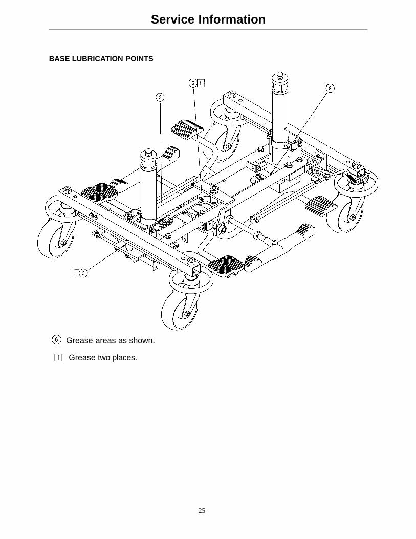
BASE LUBRICATION POINTS
Grease areas as shown.
� Grease two places.
26
Base A
ssemb
ly
Assembly part number 5050–1–200
HEAD END
FOOT END
BASE WELDMENT SHOWN UPSIDE DOWN
27
Base A
ssemb
ly
HEAD END
FOOT END
28
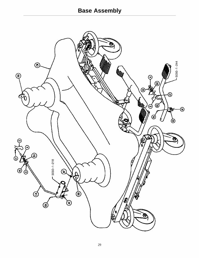
Base Assembly
29
Base Assembly
30
Base Assembly
Item Part No. Part Name Qty. Item Part No. Part Name Qty.A 42–13 Collar 3 BD 3–39 Hex Hd. Cap Screw 8B 42–20 Collar 1 BE 3–32 Hex Hd. Cap Screw 4C 715–1–11 Brake Cushion 4 BF 3–4 Hex Hd. Cap Screw 2D 715–1–61 Caster Brake Ass’y 2 BH 3–85 Hex Hd. Cap Screw 8E 715–1–92 Pump Pedal Shaft 1 BJ 38–211 Compression Spring 1F 715–1–94 Compression Spring 2 BK 38–234 Compression Spring 2H 715–1–133 Jack Spring Collar 2 BL 4–39 H. Soc. But. Hd. Cap Scr. 2J 715–1–140 Vinyl Tube 1 BM 4–300 H. Soc. But. Hd. Cap Scr. 1K (page 31) Brake Adjuster 2 BN 4–85 Soc. Hd. Cap Screw 4L 715–1–156 Ground Chain 1 BP 5050–1–10 Base Weldment 1M 715–1–158 Caster Nut 4 BR (page 33) Pump Pedal Ass’y 1N 715–1–187 Rel. Pedal Sleeve Weldmt. 1 BS 5050–1–90 Pump Pivot Ass’y 1P 715–1–192 Jack Support 1 BT 5050–1–100 Pump Link Weldment 2R 715–1–193 Jack Support Clamp 2 BW 5050–1–110 Pump Tube Weldment 1S 715–1–346 Release Paddle 2 BY 5050–1–218 Rel. Sleeve Wldmt., Ft. 1T 763–1–15 Jack Spring 2 BZ 5050–1–222 Linkage Rod, Head End 1W 763–1–16 Spring Holder 2 CA 5050–1–223 Release Linkage, Ft. End 1Y 946–1–116 Brake Bar Bushing 4 CB 5050–1–227 Brake Rod 1Z 11–2 Washer 4 CC 5050–1–229 Brake Actuator Weldmt. 2AA 11–3 Washer 4 CD 5050–1–230 Latch Assembly 1AB 11–4 Washer 8 CE (page 32) Brake Drive Link Ass’y 2AC 11–53 Washer 2 CF (page 32) Brake Cam Assembly 2AD 13–38 Ext. Tooth Lock Washer 4 CH 5050–1–235 Jack Support Clamp 1AE 14–2 Nylon Washer 15 CJ (page 34) Rel. Pedal, Hd. End, Rt. 1AF 14–4 Nylon Washer 2 CK (page 34) Rel. Pedal, Hd. End, Lt. 1AH 15–11 Hex Jam Nut 2 CL (page 35) Rel. Pedal, Ft. End, Rt. 1AJ 16–12 Nylock Hex Nut 8 CM (page 35) Rel. Pedal, Ft. End, Lt. 1AK 16–14 Dynalock Nut 1 CN (page 36) Brake Actuator, Foot 1AL 16–16 Nylock Hex Nut 6 CP (page 37) Brake Actuator, Head 1AM 16–19 Elastic Stop Nut 1 CR 5050–1–270 Steer Lock Linkage 1AN 16–2 Fiberlock Nut 4 CS (page 38) Caster Wheel Ass’y 3AP 16–3 Fiberlock Nut 4 CT (page 39) Steer Caster Wheel Ass’y 1AR 16–36 Nylock Hex Nut 10 CW (page 43) Base Hood & Label Ass’y 1AS 21–22 Set Screw 2 CY (page 41) Jack Assembly 2AT 21–50 Set Screw 4 CZ 52–245 Nyliner 3AW 23–25 Hex Wash. Hd. Tap. Screw 1 DA 8–20 Soc. Hd. Shoulder Bolt 2AY 26–13 Roll Pin 2 DB 8–7 Soc. Hd. Shoulder Bolt 2AZ 26–261 Groove Pin 2 DC 81–245 Flange Bearing 2BA 27–4 Cotter Pin 2 DD 715–1–134 Bellows 2BB 27–7 Cotter Pin 2 DE 1210–201–201 Brake/Steer Pedal 2BC 3–3 Hex Hd. Cap Screw 2 DF 11–262 Washer 4
DH 11–4 Washer 2
31
715–1–150 Brake Adjuster Assembly
Item Part No. Part Name Qty.A 715–1–62 Threaded Stud Assembly 1B 14–4 Nylon Washer 4C 715–1–180 Bearing 2D 28–8 Retaining Ring 2
32
Brake Cam Assembly
Assembly part number5050–1–234
Item Part No. Part Name Qty.A 715–301–221 Brake Cam 1B 16–59 Hex Nut 1C 5050–1–228 Brake Cam Link 1D 8–21 Socket Hd. Shoulder Bolt 1
Brake Drive Link Assembly
Assembly part number5050–1–233
Item Part No. Part Name Qty.A 5050–1–226 Brake Drive Link 1B 5050–1–232 Rod End Bearing 1
33
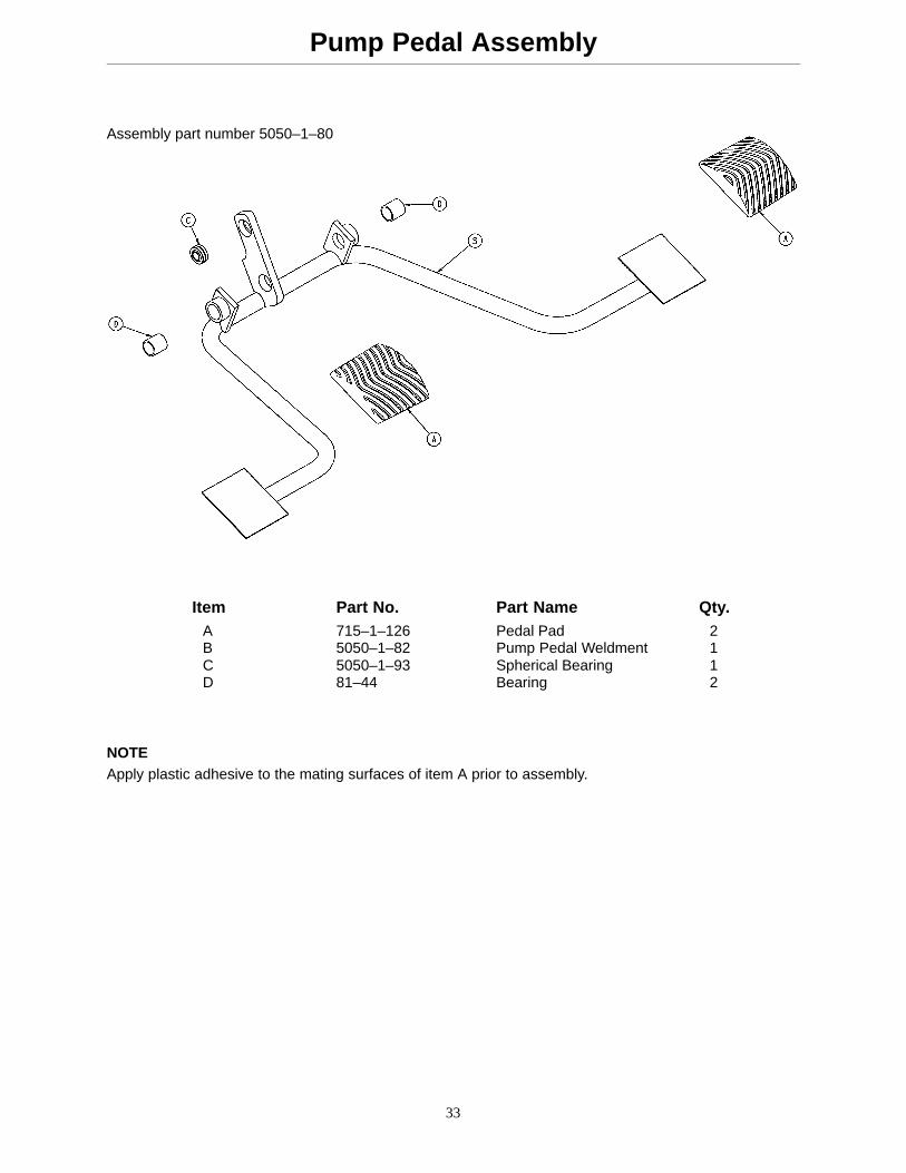
Pump Pedal Assembly
Assembly part number 5050–1–80
Item Part No. Part Name Qty.A 715–1–126 Pedal Pad 2B 5050–1–82 Pump Pedal Weldment 1C 5050–1–93 Spherical Bearing 1D 81–44 Bearing 2
NOTEApply plastic adhesive to the mating surfaces of item A prior to assembly.
34
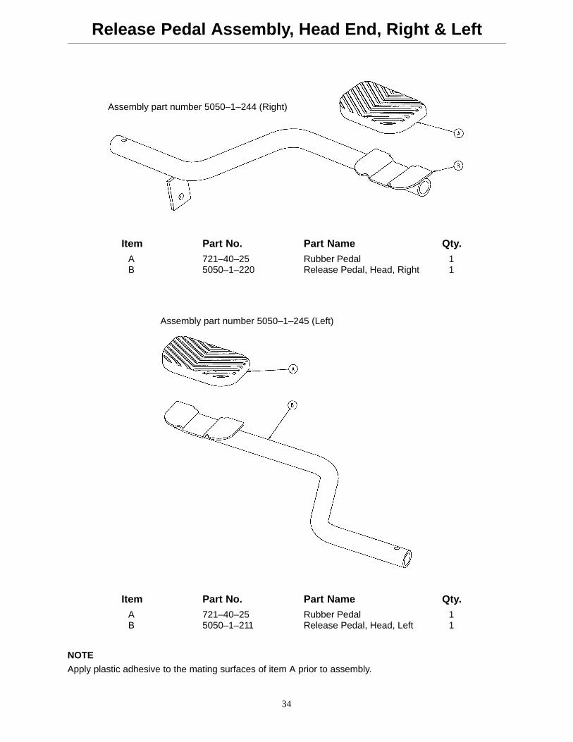
Release Pedal Assembly, Head End, Right & Left
Assembly part number 5050–1–244 (Right)
Item Part No. Part Name Qty.A 721–40–25 Rubber Pedal 1B 5050–1–220 Release Pedal, Head, Right 1
Assembly part number 5050–1–245 (Left)
Item Part No. Part Name Qty.A 721–40–25 Rubber Pedal 1B 5050–1–211 Release Pedal, Head, Left 1
NOTE
Apply plastic adhesive to the mating surfaces of item A prior to assembly.
35
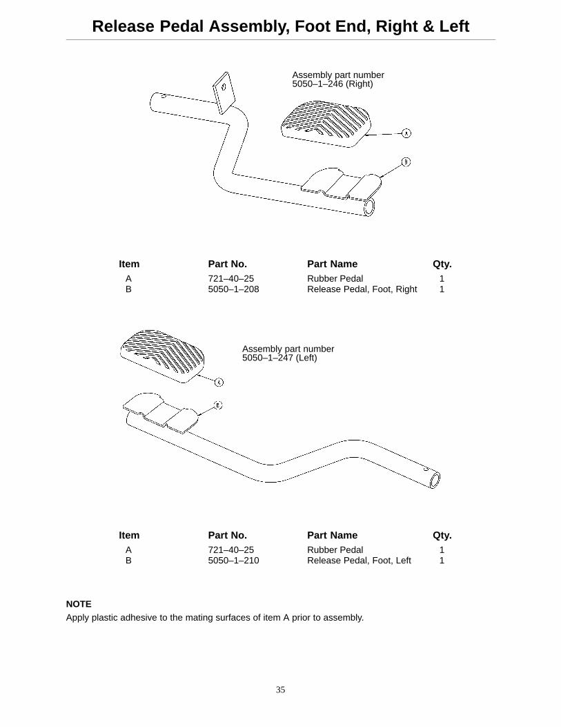
Release Pedal Assembly, Foot End, Right & Left
Assembly part number5050–1–246 (Right)
Item Part No. Part Name Qty.A 721–40–25 Rubber Pedal 1B 5050–1–208 Release Pedal, Foot, Right 1
Assembly part number5050–1–247 (Left)
Item Part No. Part Name Qty.A 721–40–25 Rubber Pedal 1B 5050–1–210 Release Pedal, Foot, Left 1
NOTEApply plastic adhesive to the mating surfaces of item A prior to assembly.
36
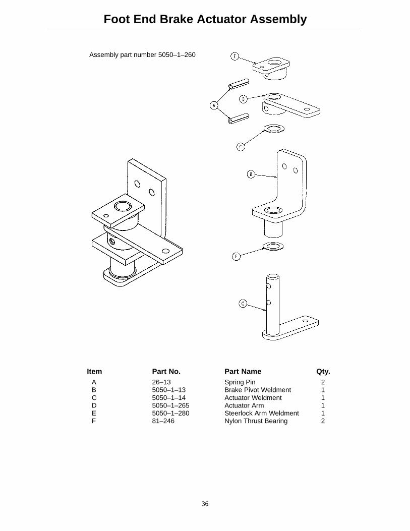
Foot End Brake Actuator Assembly
Assembly part number 5050–1–260
Item Part No. Part Name Qty.A 26–13 Spring Pin 2B 5050–1–13 Brake Pivot Weldment 1C 5050–1–14 Actuator Weldment 1D 5050–1–265 Actuator Arm 1E 5050–1–280 Steerlock Arm Weldment 1F 81–246 Nylon Thrust Bearing 2
37
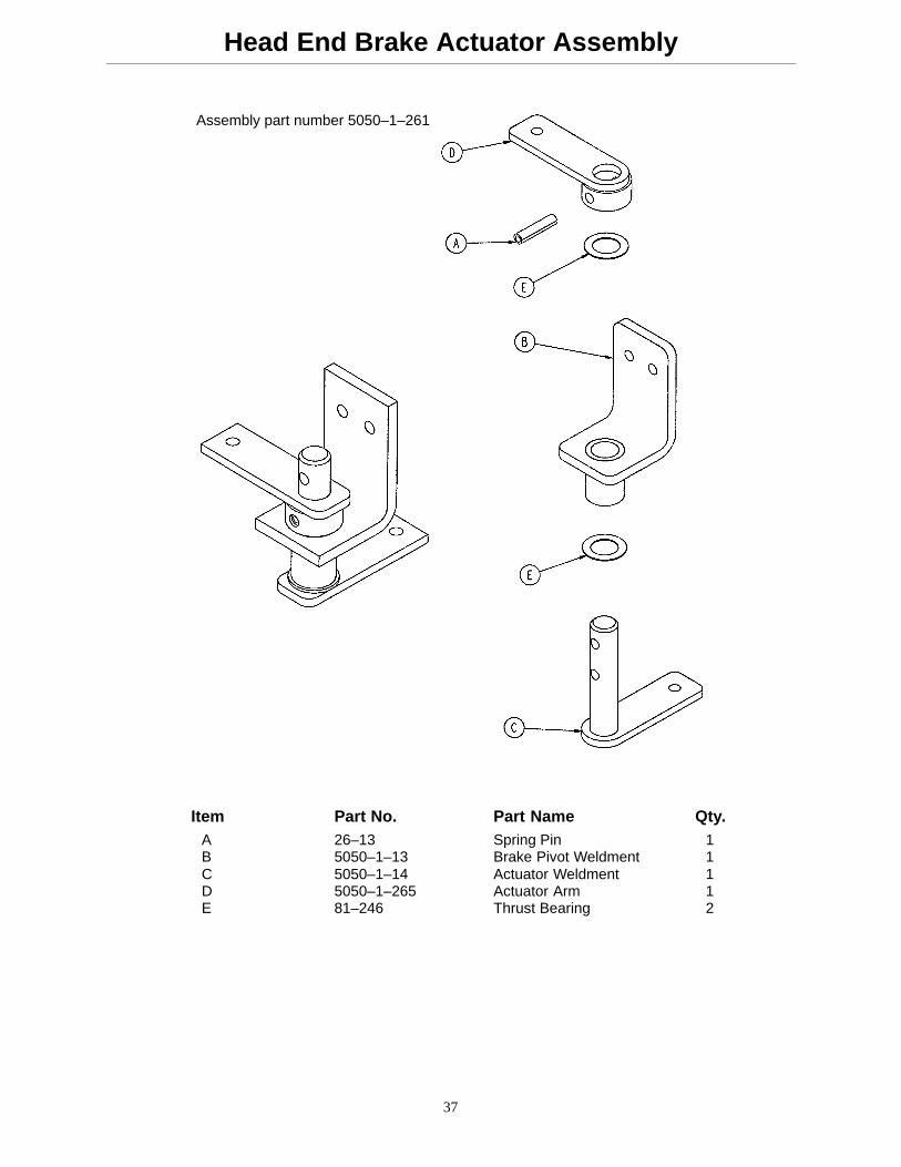
Head End Brake Actuator Assembly
Assembly part number 5050–1–261
Item Part No. Part Name Qty.A 26–13 Spring Pin 1B 5050–1–13 Brake Pivot Weldment 1C 5050–1–14 Actuator Weldment 1D 5050–1–265 Actuator Arm 1E 81–246 Thrust Bearing 2
38
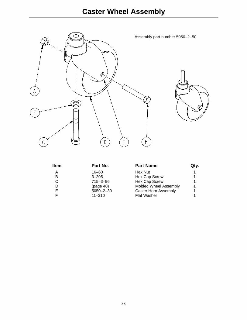
Caster Wheel Assembly
Assembly part number 5050–2–50
Item Part No. Part Name Qty.A 16–60 Hex Nut 1B 3–205 Hex Cap Screw 1C 715–3–96 Hex Cap Screw 1D (page 40) Molded Wheel Assembly 1E 5050–2–30 Caster Horn Assembly 1F 11–310 Flat Washer 1
39
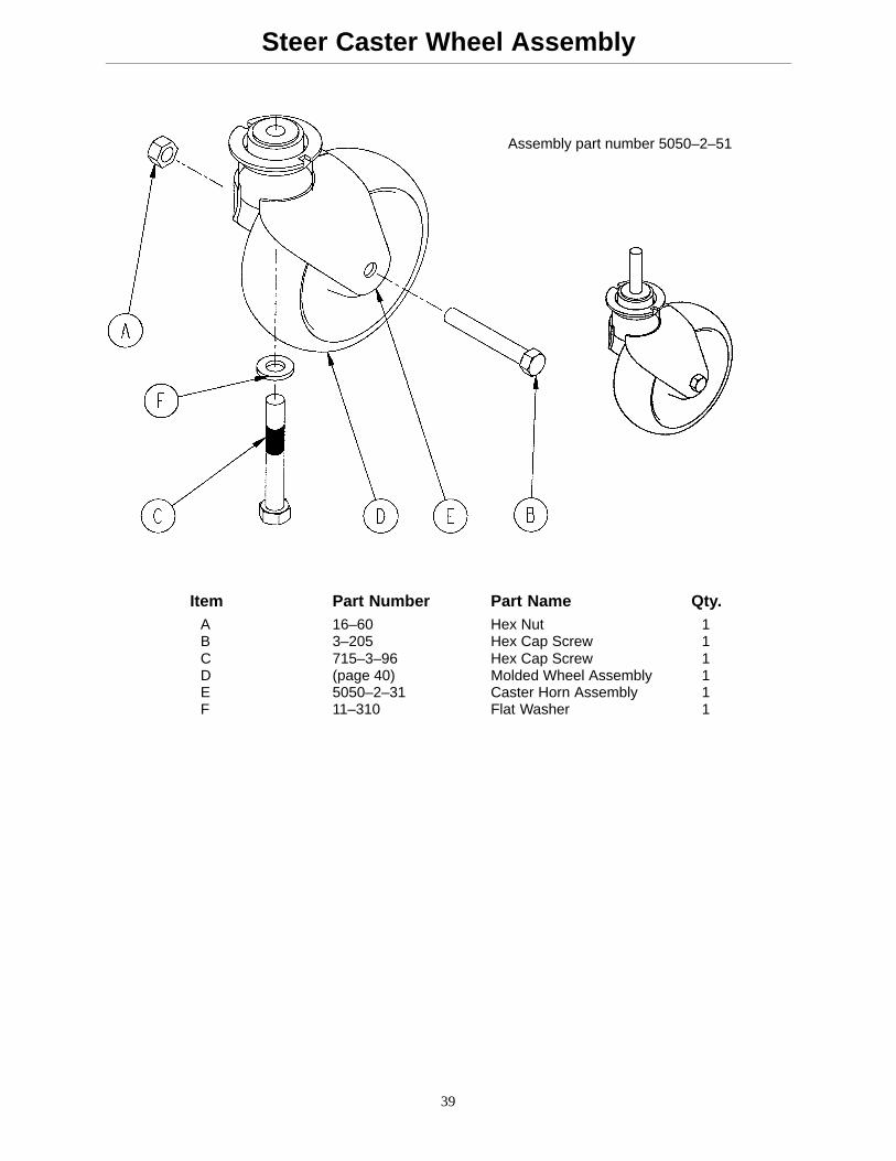
Steer Caster Wheel Assembly
Assembly part number 5050–2–51
Item Part Number Part Name Qty.A 16–60 Hex Nut 1B 3–205 Hex Cap Screw 1C 715–3–96 Hex Cap Screw 1D (page 40) Molded Wheel Assembly 1E 5050–2–31 Caster Horn Assembly 1F 11–310 Flat Washer 1
40
Molded Wheel Assembly
Assembly part number5050–2–10
Item Part No. Part Name Qty.A 81–226 Bearing 2B 715–1–255 Wheel Bushing 2C 5050–2–20 Molded Wheel 1D 6060–2–41 Bearing Spacer 1
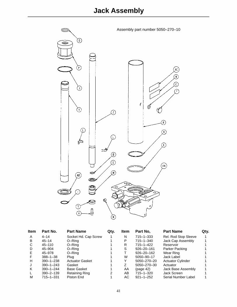
Jack Assembly
41
Assembly part number 5050–270–10
Item Part No. Part Name Qty. Item Part No, Part Name Qty.A 4–14 Socket Hd. Cap Screw 1 N 715–1–333 Rel. Rod Stop Sleeve 1B 45–14 O–Ring 1 P 715–1–340 Jack Cap Assembly 1C 45–110 O–Ring 1 R 715–1–422 Reservoir 1D 45–904 O–Ring 1 S 926–20–161 Parker Packing 1E 45–978 O–Ring 1 T 926–20–162 Wear Ring 1F 388–1–38 Plug 1 W 5050–90–17 Jack Label 1H 390–1–238 Actuator Gasket 1 Y 5050–270–20 Actuator Cylinder 1J 390–1–243 Gasket 1 Z 5050–270–30 Actuator 1K 390–1–244 Base Gasket 1 AA (page 42) Jack Base Assembly 1L 390–2–139 Retaining Ring 2 AB 715–1–320 Jack Screen 1M 715–1–331 Piston End 1 AC 921–1–252 Serial Number Label 1
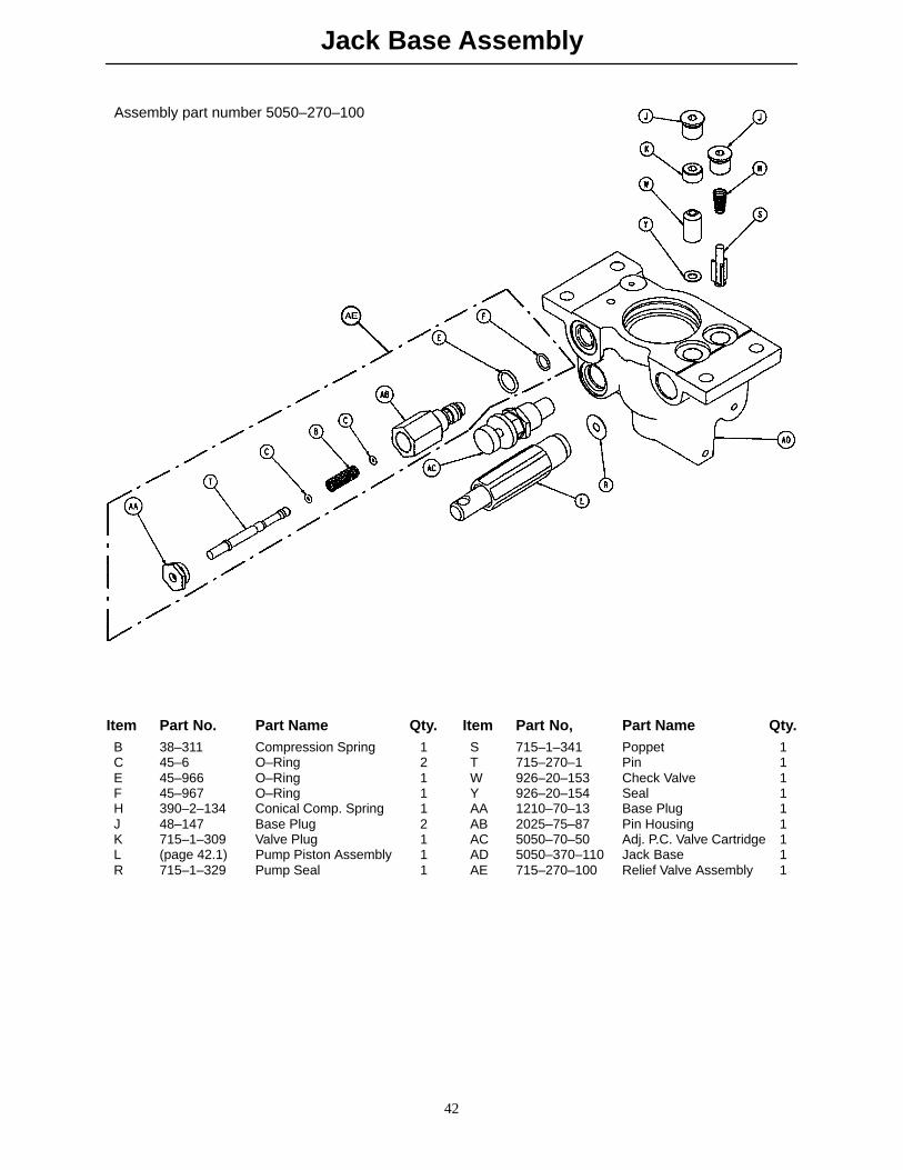
Jack Base Assembly
42
Assembly part number 5050–270–100
Item Part No. Part Name Qty. Item Part No, Part Name Qty.B 38–311 Compression Spring 1 S 715–1–341 Poppet 1C 45–6 O–Ring 2 T 715–270–1 Pin 1E 45–966 O–Ring 1 W 926–20–153 Check Valve 1F 45–967 O–Ring 1 Y 926–20–154 Seal 1H 390–2–134 Conical Comp. Spring 1 AA 1210–70–13 Base Plug 1J 48–147 Base Plug 2 AB 2025–75–87 Pin Housing 1K 715–1–309 Valve Plug 1 AC 5050–70–50 Adj. P.C. Valve Cartridge 1L (page 42.1) Pump Piston Assembly 1 AD 5050–370–110 Jack Base 1R 715–1–329 Pump Seal 1 AE 715–270–100 Relief Valve Assembly 1
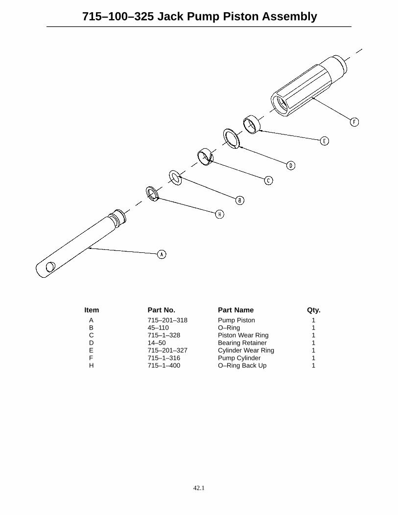
715–100–325 Jack Pump Piston Assembly
42.1
Item Part No. Part Name Qty.A 715–201–318 Pump Piston 1B 45–110 O–Ring 1C 715–1–328 Piston Wear Ring 1D 14–50 Bearing Retainer 1E 715–201–327 Cylinder Wear Ring 1F 715–1–316 Pump Cylinder 1H 715–1–400 O–Ring Back Up 1
Notes
42.2
43
Base Hood/Label Assembly
Assembly part numbers 5050–10–1 &
C
C
D B E A 5050–10–10 (w/optional removable I.V.)
F
J
K
A
H
Item Part No. Part Name Qty.A 5050–10–2 Base Hood 1B 921–1–252 Serial Number Label 1C 946–1–60 Stryker Logo Label 2D 5050–90–1 Specification Label 1E 5050–90–15 Weight Capacity Label 1F 4–57 Soc. Hd. Cap Screw 2H 16–27 Kep Nut 2J 946–1–108 I.V. Clip 2K 946–1–109 Adhesive Pad 2
p/n 5050–90–15 – located on the base hood.
p/n 5050–90–7 – located on the foot section.
p/n 5050–90–6 – located on both head and foot sections.
These three labels are critical to the safe operation of the Stretcher Chair. If they are not present and ingood condition, they must be replaced.
44
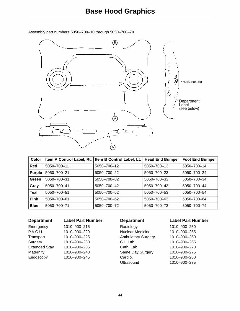
Base Hood Graphics
A
A
B
Assembly part numbers 5050–700–10 through 5050–700–70
Color Item A Control Label, Rt. Item B Control Label, Lt. Head End Bumper Foot End Bumper
Red 5050–700–11 5050–700–12 5050–700–13 5050–700–14
Blue 5050–700–71 5050–700–72 5050–700–73 5050–700–74
Department Label Part Number Department Label Part NumberEmergency 1010–900–215 Radiology 1010–900–250P.A.C.U. 1010–900–220 Nuclear Medicine 1010–900–255Transport 1010–900–225 Ambulatory Surgery 1010–900–260Surgery 1010–900–230 G.I. Lab 1010–900–265Extended Stay 1010–900–235 Cath. Lab 1010–900–270Maternity 1010–900–240 Same Day Surgery 1010–900–275Endoscopy 1010–900–245 Cardio. 1010–900–280
Ultrasound 1010–900–285
45
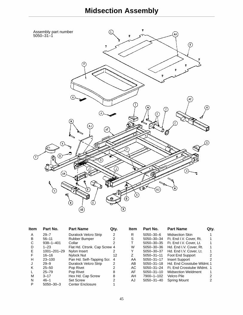
Midsection Assembly
Assembly part number5050–31–1
Item Part No. Part Name Qty. Item Part No. Part Name Qty.A 29–7 Duralock Velcro Strip 2 R 5050–30–6 Midsection Skin 1B 56–11 Rubber Bumper 2 S 5050–30–34 Ft. End I.V. Cover, Rt. 1C 938–1–401 Collar 2 T 5050–30–35 Ft. End I.V. Cover, Lt. 1D 1–23 Flat Hd. Ctrsnk. Cap Screw 4 W 5050–30–36 Hd. End I.V. Cover, Rt. 1E 1001–201–29 Nylon Insert 2 Y 5050–30–37 Hd. End I.V. Cover, Lt. 1F 16–16 Nylock Nut 12 Z 5050–31–11 Foot End Support 2H 23–100 Pan Hd. Self–Tapping Scr. 4 AA 5050–31–17 Insert Support 2J 29–9 Duralock Velcro Strip 2 AB 5050–31–18 Hd. End Crosstube Wldmt.1K 25–50 Pop Rivet 2 AC 5050–31–24 Ft. End Crosstube Wldmt. 1L 25–79 Pop Rivet 8 AF 5050–31–10 Midsection Weldment 1M 3–17 Hex Hd. Cap Screw 8 AH 7900–1–102 Velcro Pile 2N 46–1 Set Screw 2 AJ 5050–31–40 Spring Mount 2P 5050–30–3 Center Enclosure 1
46
Fo
wler A
ssemb
ly
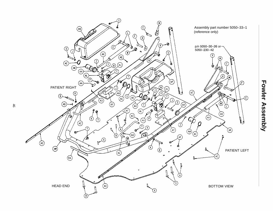
Assembly part number 5050–33–1
HEAD END
PATIENT RIGHT
PATIENT LEFT
BOTTOM VIEW
(reference only)
47
Fowler Assembly
Item Part No. Part Name Qty.A 4–57 Hex Soc. But. Hd. Cap Screw 6B 4–97 Hex Soc. But. Hd. Cap Screw 2C 4–130 Hex Soc. But. Hd. Cap Screw 2D 4–135 But. Hd. Cap Screw 2E 4–303 Hex Soc. Hd. Cap Screw 2F 4–257 H. Soc. Flat Ctrsnk. Hd. Cap Scr. 2H 7–34 Truss Hd. Mach. Screw 6J 11–132 Nylon Washer 4K 14–2 Nylon Washer 4L 14–9 Nylon Washer 4M 14–19 Nylon Washer 8N 15–37 Hex Jam Nut 2P 15–50 Hex Nut 2R 16–11 Nylock Hex Nut 4S 16–14 Dynalock Nut 6T 16–16 Nylon Lock Nut 10W 16–90 Nylock Nut 2Y 21–125 Set Screw 2Z 21–119 Set Screw 2AA 21–126 Set Screw 2AB 25–38 Pop Rivet 20AC 25–50 Pop Rivet 14AD 27–17 Cotter Pin 4AE 28–76 Retaining Ring 4AF 716–1–286 Release Pedal Cam 4AH 946–35–25 Liner 4AJ 1001–31–30 Yoke Housing 2AK 360–31–77 Gas Cylinder 2AL 1060–1–66 Pneumatic Trigger 2AM 1510–31–28 Yoke 2AN 5050–30–4 Fowler Enclosure, Right 1AP 5050–30–5 Fowler Enclosure, Left 1AR 5050–30–8 Fowler Skin 1AS 5050–30–30 Head End Bumper Channel 2AT 5050–33–10 Fowler Weldment 1AW 5050–33–16 Trip Bar Weldment 1AY 5050–33–18 Spacer 2AZ 5050–33–19 Trip Bar Link 2BA 5050–90–6 Head/Foot End Warning Label 1BB 7900–1–102 Velcro Pile 36”
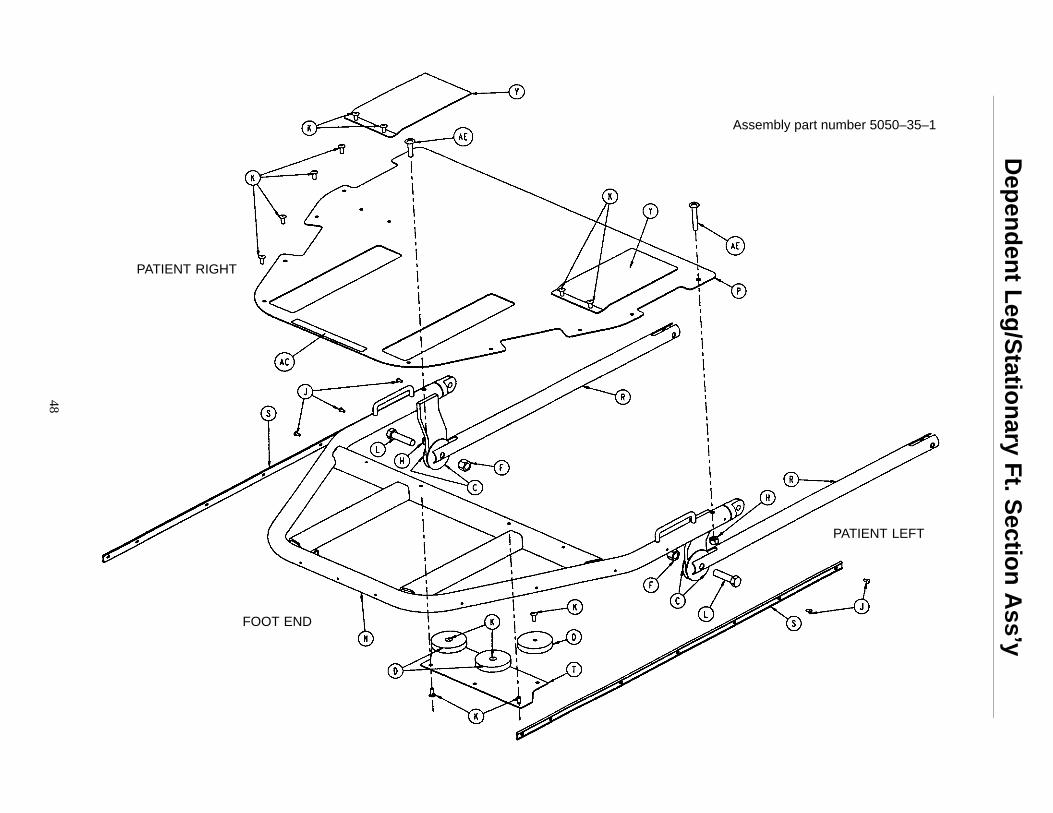
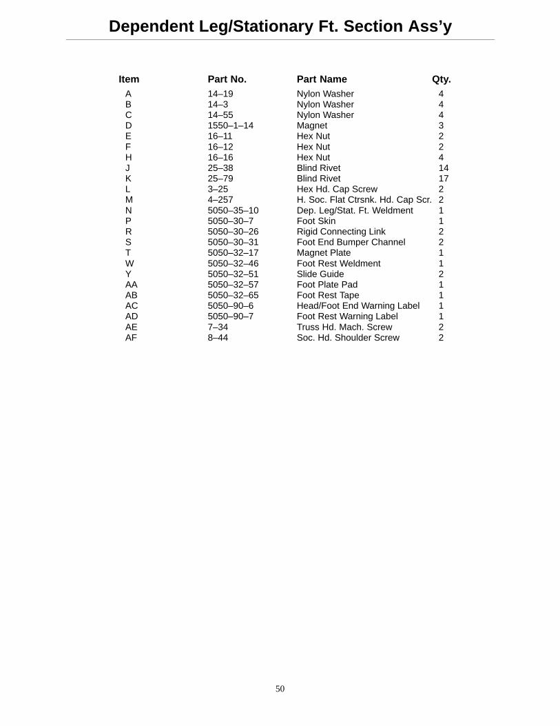
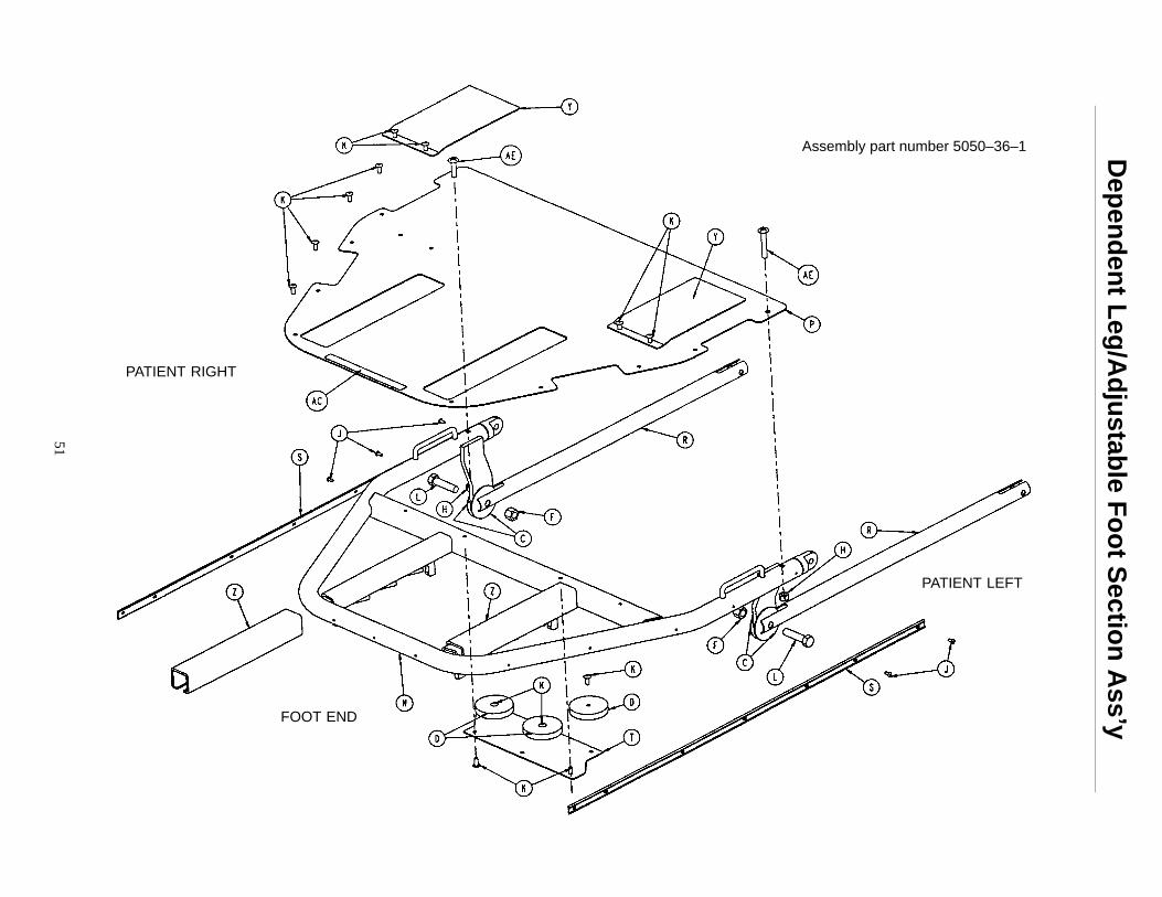
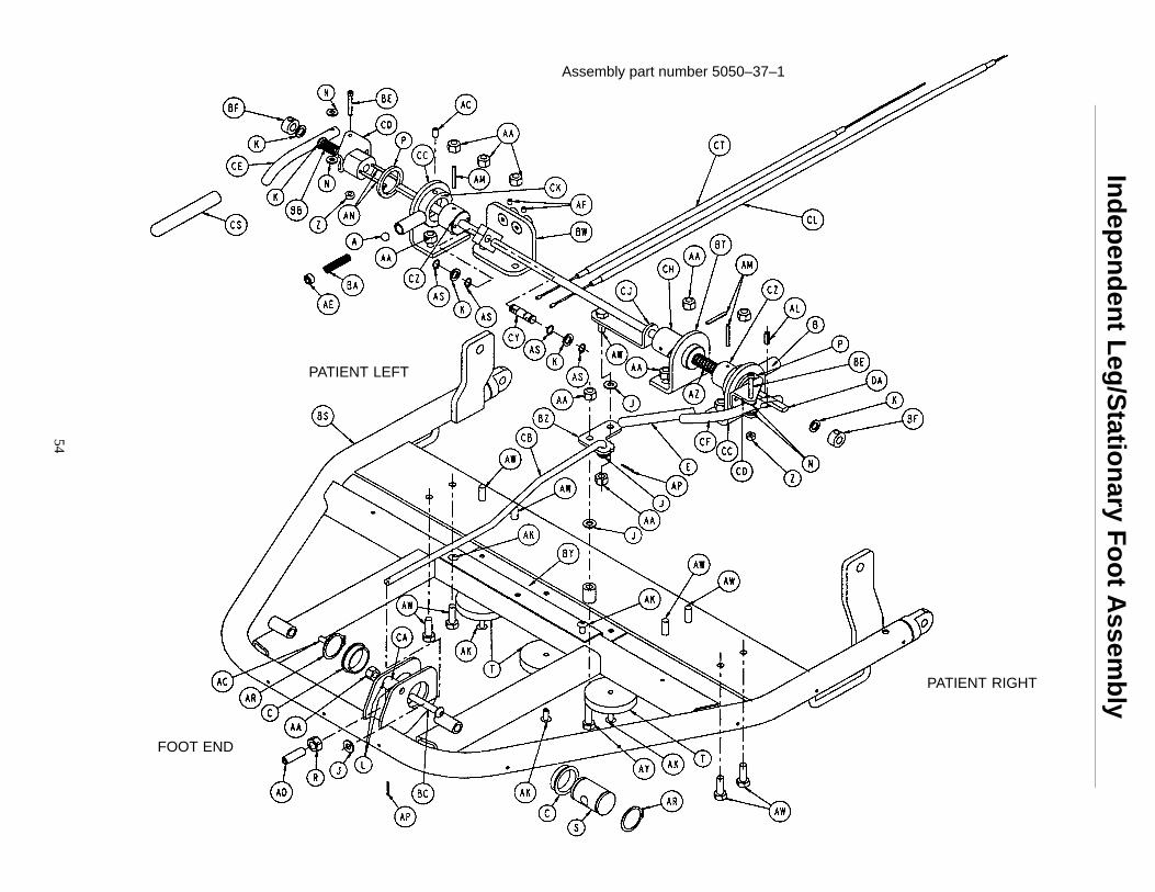
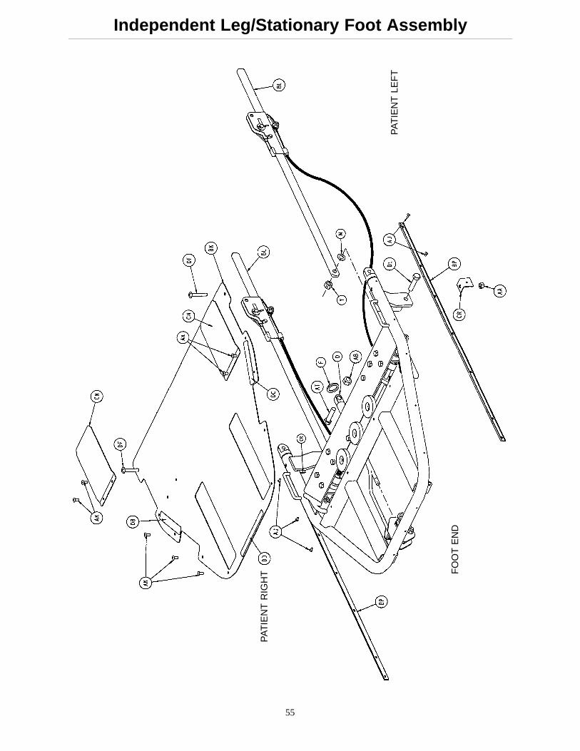
Item Part No. Part Name Qty. Item Part No. Part Name Qty.A 81–247 Ball Bearing 1 BE 4–82 Soc. Hd. Cap Screw 2B 938–1–401 Collar 1 BF 42–22 Locking Collar 2C 946–35–25 Liner 2 BH 5050–30–1 Right Side Enclosure 1D 1010–31–77 Gas Cylinder 1 BJ 5050–30–2 Left Side Enclosure 1E 1068–234–36 Handle Grip 1 BK 5050–30–7 Foot Skin 1F 11–379 Steel Washer 1 BL (page 62) Locking Link, Right 1H 14–19 Nylon Washer 4 BM (page 63) Locking Link, Left 1J 14–2 Nylon Washer 4 BN 5050–30–28 Side Enclosure Bracket 4K 14–3 Nylon Washer 8 BP 5050–30–31 Ft. End Bumper Channel 2L 14–4 Nylon Washer 2 BR 5050–30–32 Foot Section Cover 1M 14–55 Nylon Washer 4 BS 5050–37–10 Indep. Leg/Stat. Ft. Wldmt. 1N 14–56 Nylon Washer 4 BT 5050–32–12 Swivel Weldment 1P 14–63 Nylon Washer 2 BW 5050–32–15 Cable Bracket Wldmt. 1R 15–50 Hex Nut 1 BY 5050–32–17 Magnet Plate 1S 1510–31–28 Yoke 1 BZ 5050–32–18 Spring Rocker 1T 1550–1–14 Magnet 3 CA 5050–32–19 Spring Actuator 1W 16–11 Nylock Hex Nut 2 CB 5050–32–22 Tie Rod 1Y 16–12 Nylock Hex Nut 2 CC 5050–32–23 L–Bracket Weldment 2Z 16–23 Nylock Hex Nut 2 CD 5050–32–27 Handle Mount Weldment 2AA 16–16 Nylock Hex Nut 15 CE 5050–32–30 Left Handle 1AB 16–90 Nylock Hex Nut 1 CF 5050–32–32 Right Handle 1AC 21–119 Set Screw 2 CH 5050–32–34 Nylon Swivel 1AD 21–126 Set Screw 1 CJ 5050–32–35 Spring Pusher 1AE 21–141 Set Screw 1 CK 5050–32–36 Stop Collar 1AF 21–8 Set Screw 2 CL 5050–32–39 Long Cable w/Cover 1AH 23–71 Hex Wash. Hd. Tap. Scr. 12 CM 5050–32–46 Foot Rest Weldment 1AJ 25–38 Blind Rivet 14 CN 5050–32–51 Slide Guide 2AK 25–79 Blind Rivet 17 CR 5050–32–53 Foot Cover L–Bracket 2AL 26–233 Roll Pin 1 CS 5050–32–54 Left Handle Cover 1AM 26–7 Roll Pin 3 CT 5050–32–40 Release Cable 1AN 26–8 Roll Pin 4 CW 5050–32–57 Foot Plate Pad 1AP 27–4 Cotter Pin 2 CY 5050–32–60 Cable Pivot 1AR 28–76 External Retaining Ring 2 CZ 5050–32–62 Handle Timing Swivel 2AS 28–89 External Retaining Ring 4 DA 5050–32–63 Handle Rod Weldment 1AT 3–209 Hex Hd. Cap Screw 1 DB 5050–90–4 Foot Section Label, Rt. 1AW 3–50 Hex Hd. Cap Screw 9 DC 5050–90–5 Foot Section Label, Lt. 1AY 3–74 Hex Hd. Cap Screw 1 DD 5050–90–6 Hd./Ft. End Warning Label 1AZ 38–331 Compression Spring 1 DE 5050–90–7 Foot Rest Warning Label 1BA 38–332 Compression Spring 1 DF 7–34 Truss Hd. Mach. Screw 2BB 38–334 Compression Spring 1 DH 8–44 Soc. Hd. Shoulder Screw 2BC 4–135 H. Soc. But. Hd. Cap Scr. 1 DK 5050–32–65 Foot Rest Tape 1BD 4–257 Flat Ctrsnk. Hd. Cap Scr. 2 DL 3–25 Hex Hd. Cap Screw 2
58
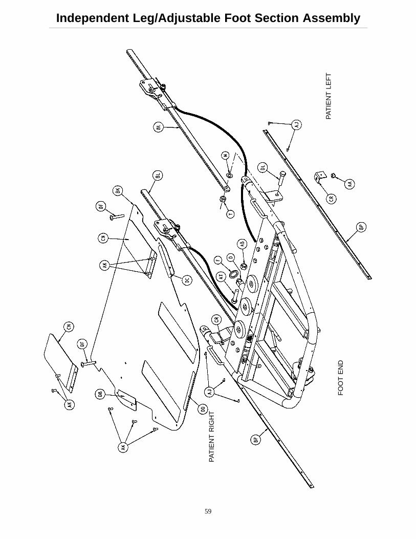
Independent Leg/Adjustable Foot Section Assembly
FO
OT
EN
D
BO
TT
OM
VIE
W
Ass
embl
y pa
rt n
umbe
r 50
50–3
2–1
59
Independent Leg/Adjustable Foot Section Assembly
PA
TIE
NT
LE
FT
PA
TIE
NT
RIG
HT
FO
OT
EN
D
60
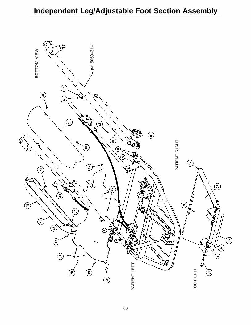
Independent Leg/Adjustable Foot Section Assembly
PA
TIE
NT
LE
FT
FO
OT
EN
D
PA
TIE
NT
RIG
HT
BO
TT
OM
VIE
W
61
Independent Leg/Adjustable Foot Section Assembly
Item Part No. Part Name Qty. Item Part No. Part Name Qty.A 81–247 Ball Bearing 1 BF 42–22 Locking Collar 2B 938–1–401 Collar 1 BH 5050–30–1 Right Side Enclosure 1C 946–35–25 Liner 2 BJ 5050–30–2 Left Side Enclosure 1D 1010–31–77 Gas Cylinder 1 BK 5050–30–7 Foot Skin 1E 1068–234–36 Handle Grip 1 BL (page 62) Locking Link, Right 2F 11–379 Steel Washer 1 BM (page 63) Locking Link, Left 1H 14–19 Nylon Washer 4 BN 5050–30–28 Side Enclosure Bracket 4J 14–2 Nylon Washer 4 BP 5050–30–31 Foot End Bumper Channel 2K 14–3 Nylon Washer 8 BR 5050–30–32 Foot Section Cover 1L 14–4 Nylon Washer 2 BS 5050–32–10 Ind. Leg/Adj. Ft. Wldmt. 1M 14–55 Nylon Washer 4 BT 5050–32–12 Swivel Weldment 1N 14–56 Nylon Washer 4 BW 5050–32–15 Cable Bracket Weldment 1P 14–63 Nylon Washer 2 BY 5050–32–17 Magnet Plate 1R 15–50 Hex Nut 1 BZ 5050–32–18 Spring Rocker 1S 1510–31–28 Yoke 1 CA 5050–32–19 Spring Actuator 1T 1550–1–14 Magnet 3 CB 5050–32–22 Tie Rod 1W 16–11 Nylock Hex Nut 2 CC 5050–32–23 L–Bracket Weldment 2Y 16–12 Nylock Hex Nut 2 CD 5050–32–27 Handle Mount Weldment 2Z 16–23 Nylock Hex Nut 2 CE 5050–32–30 Left Handle 1AA 16–16 Nylock Hex Nut 13 CF 5050–32–32 Right Handle 1AB 16–90 Nylock Hex Nut 1 CH 5050–32–34 Nylon Swivel 1AC 21–119 Set Screw 2 CJ 5050–32–35 Spring Pusher 1AD 21–126 Set Screw 1 CK 5050–32–36 Stop Collar 1AE 21–141 Set Screw 1 CL 5050–32–40 Release Cable 1AF 21–8 Set Screw 2 CM 5050–32–46 Foot Rest Weldment 1AH 23–71 Hex Wash. Hd. Tap. Scr. 12 CN 5050–32–51 Slide Guide 2AJ 25–38 Blind Rivet 14 CP 5050–32–52 Channel 2AK 25–79 Blind Rivet 17 CR 5050–32–53 Foot Cover L–Bracket 2AL 26–233 Roll Pin 1 CS 5050–32–54 Left Handle Cover 1AM 26–7 Roll Pin 3 CT 5050–32–40 Release Cable 1AN 26–8 Roll Pin 4 CW 5050–32–57 Foot Plate Pad 1AP 27–4 Cotter Pin 2 CY 5050–32–60 Cable Pivot 1AR 28–76 External Retaining Ring 2 CZ 5050–32–62 Handle Timing Swivel 2AS 28–89 External Retaining Ring 4 DA 5050–32–63 Handle Rod Weldment 1AT 3–209 Hex Hd. Cap Screw 1 DB 5050–90–4 Foot Section Label, Right 1AW 3–50 Hex Hd. Cap Screw 9 DC 5050–90–5 Foot Section Label, Left 1AY 3–74 Hex Hd. Cap Screw 1 DD 5050–90–6 Hd./Ft. End Warning Label 1AZ 38–331 Compression Spring 1 DE 5050–90–7 Foot Rest Warning Label 1BA 38–332 Compression Spring 1 DF 7–34 Truss Hd. Mach. Screw 2BB 38–334 Compression Spring 1 DH 8–44 Soc. Hd. Shoulder Screw 2BC 4–135 H. Soc. But. Hd. Cap Scr. 1 DK 5050–32–65 Foot Rest Tape 1BD 4–257 Flat Ctrsnk. Hd. Cap Scr. 2 DL 3–25 Hex Hd. Cap Screw 2BE 4–82 Soc. Hd. Cap Screw 2
62
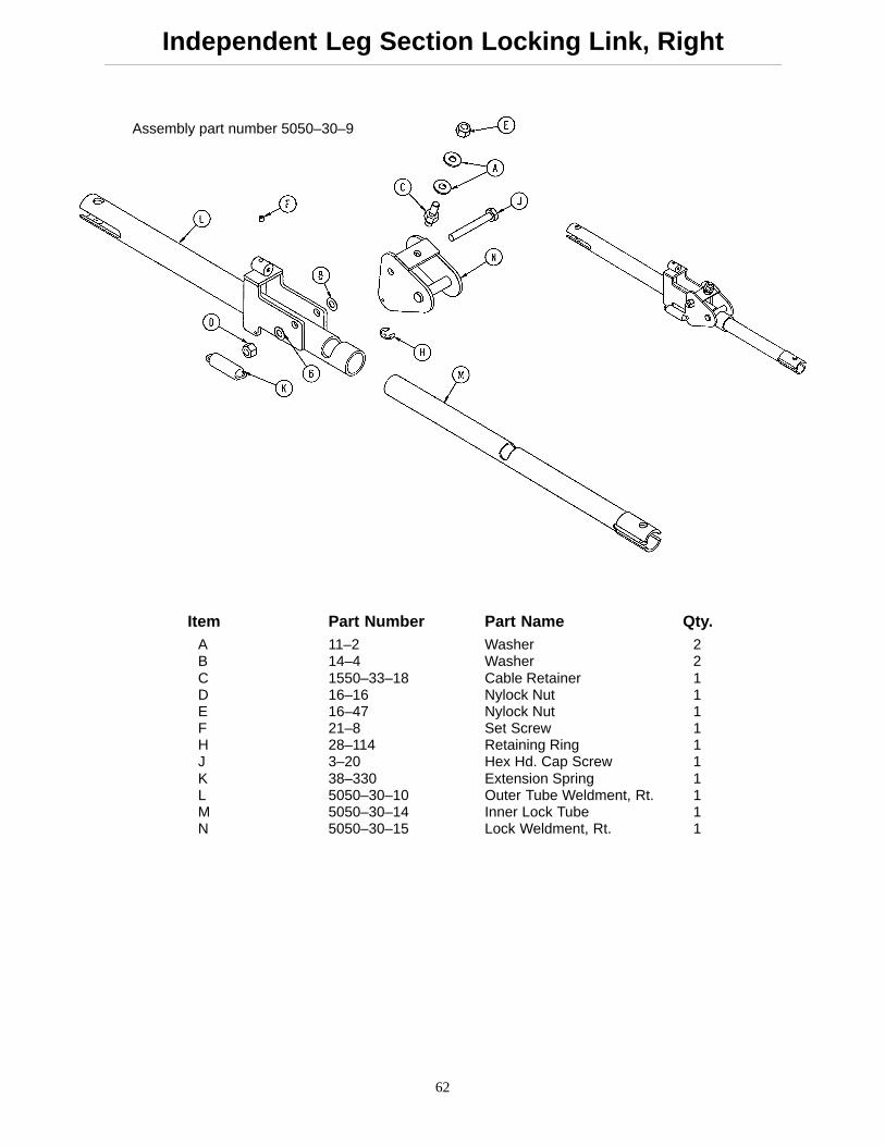
Independent Leg Section Locking Link, Right
Assembly part number 5050–30–9
Item Part Number Part Name Qty.A 11–2 Washer 2B 14–4 Washer 2C 1550–33–18 Cable Retainer 1D 16–16 Nylock Nut 1E 16–47 Nylock Nut 1F 21–8 Set Screw 1H 28–114 Retaining Ring 1J 3–20 Hex Hd. Cap Screw 1K 38–330 Extension Spring 1L 5050–30–10 Outer Tube Weldment, Rt. 1M 5050–30–14 Inner Lock Tube 1N 5050–30–15 Lock Weldment, Rt. 1
63
Independent Leg Section Locking Link, Left
Assembly part number 5050–30–21
Item Part No. Part Name Qty.A 11–2 Washer 2B 14–4 Washer 2C 1550–33–18 Cable Retainer 1D 16–16 Nylock Nut 1E 16–47 Nylock Nut 1F 21–8 Set Screw 1H 28–114 Retaining Ring 1J 3–20 Hex Hd. Cap Screw 1K 38–330 Extension Spring 1L 5050–30–14 Inner Lock Tube 1M 5050–30–24 Outer Tube Weldment, Lt. 1N 5050–30–25 Lock Weldment, Lt. 1
63.1
5050–30–42 Locking Link Assembly*
Item Part No. Part Name Qty.A 3–20 Hex Hd. Cap Screw 1B 11–2 Steel Washer 1C 14–4 Nylon Washer 2D 16–16 Nylon Lock Nut 1E 16–47 Nylon Lock Nut 1F 21–8 Set Screw 1H 28–114 E–Ring 1J 38–330 Extension Spring 1K 1550–33–18 Cable Retainer 1L 5050–30–14 Inner Lock Tube 1M 5050–30–40 Outer Lock Tube Weldment 1N 5050–30–41 Lock Weldment 1
*For stretcher chairs with serial numbers of 9604032789 and higher.
63.2
Notes
64
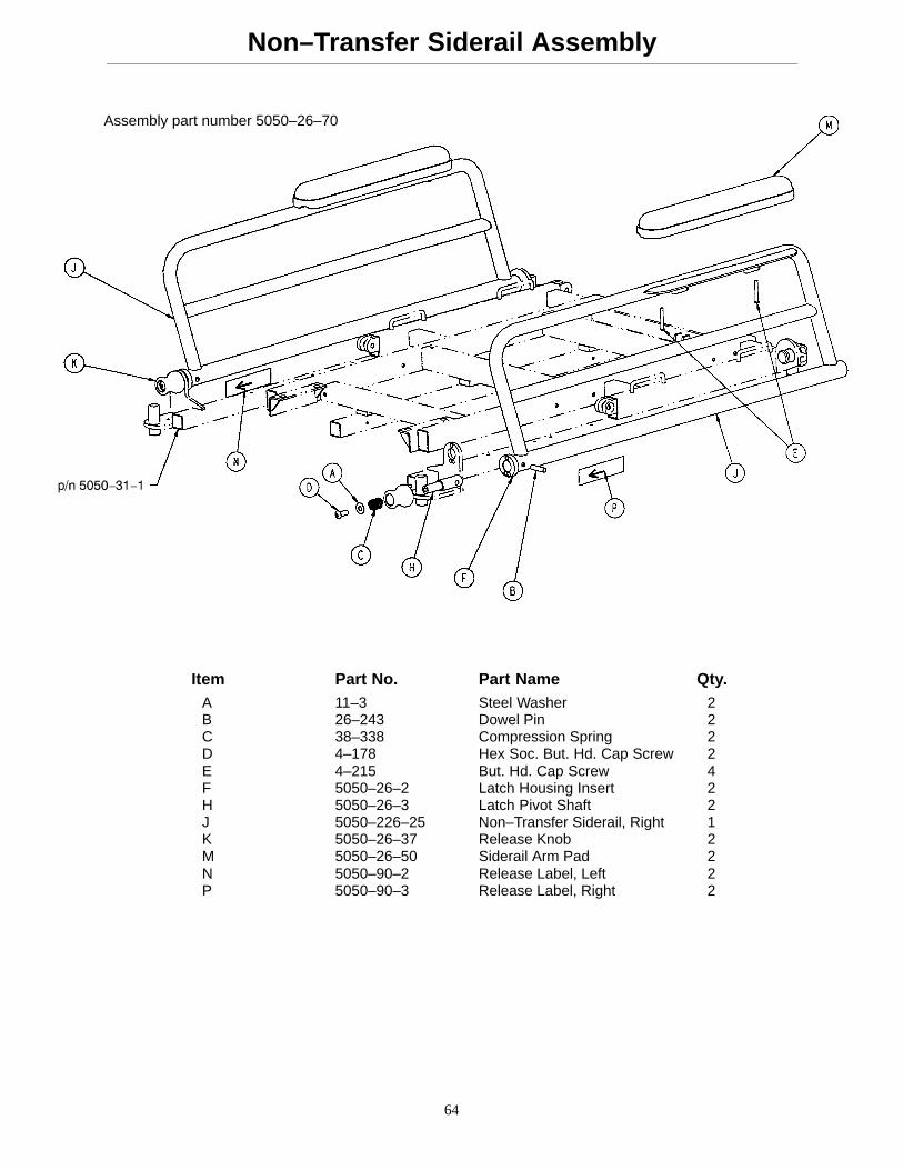
Non–Transfer Siderail Assembly
Assembly part number 5050–26–70
Item Part No. Part Name Qty.A 11–3 Steel Washer 2B 26–243 Dowel Pin 2C 38–338 Compression Spring 2D 4–178 Hex Soc. But. Hd. Cap Screw 2E 4–215 But. Hd. Cap Screw 4F 5050–26–2 Latch Housing Insert 2H 5050–26–3 Latch Pivot Shaft 2J 5050–226–25 Non–Transfer Siderail, Right 1K 5050–26–37 Release Knob 2M 5050–26–50 Siderail Arm Pad 2N 5050–90–2 Release Label, Left 2P 5050–90–3 Release Label, Right 2
65
Transfer Siderail Assembly
Assembly part number 5050–26–60
Item Part No. Part Name Qty.A 2–100 Pan Hd. Mach. Screw 4B 4–178 Hex Soc. But. Hd. Cap Screw 2C 11–3 Washer 2D 16–3 Fiberlock Nut 4E 26–233 Roll Pin 2F 26–259 Dowel 2H 38–338 Compression Spring 2J 5050–26–2 Latch Housing Insert 2K 5050–26–3 Latch Pivot Shaft 2L 5050–26–37 Release Knob, Left 1M 5050–26–38 Release Knob, Right 1N 5050–26–51 Transfer Siderail Ass’y, Left 1P 5050–26–52 Transfer Siderail Ass’y, Right 1R (page 66) Board Support Assembly 2S 5050–90–2 Siderail Release Label, Left 2T 5050–90–3 Siderail Release Label, Right 2W 5050–90–14 Transfer Board Release Label 2X 14–21 Nylon Washer 2
66
Board Support Assembly
Assembly part number 5050–26–80
Item Part No. Part Name Qty.A 8–15 Socket Hd. Shoulder Bolt 1B 33–2 Ball Knob 1C 38–368 Compression Spring 1D 1010–24–14 Warning Label 1E 5050–26–81 Support Block 1F 5050–26–82 Support Arm 1
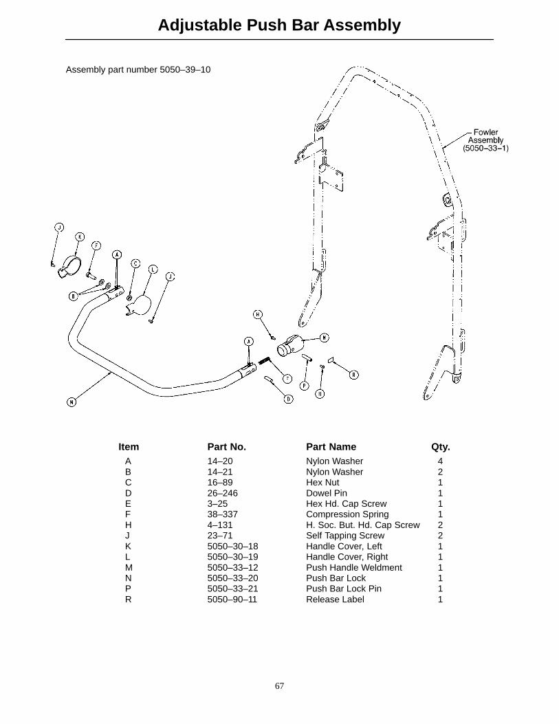
Adjustable Push Bar Assembly
67
Assembly part number 5050–39–10
Item Part No. Part Name Qty.A 14–20 Nylon Washer 4B 14–21 Nylon Washer 2C 16–89 Hex Nut 1D 26–246 Dowel Pin 1E 3–25 Hex Hd. Cap Screw 1F 38–337 Compression Spring 1H 4–131 H. Soc. But. Hd. Cap Screw 2J 23–71 Self Tapping Screw 2K 5050–30–18 Handle Cover, Left 1L 5050–30–19 Handle Cover, Right 1M 5050–33–12 Push Handle Weldment 1N 5050–33–20 Push Bar Lock 1P 5050–33–21 Push Bar Lock Pin 1R 5050–90–11 Release Label 1
Stationary Push Bar Assembly
68
Assembly part number 5050–38–10
Item Part No. Part Name Qty.A 3–25 Hex Hd. Cap Screw 2B 23–71 Self Tapping Screw 4C 4–130 H. Soc. But. Hd. Cap Screw 2E 14–21 Nylon Washer 4F 16–36 Nylon Hex Nut 2H 16–89 Hex Nut 2J 8839–793–700 Hex Hd. Cap Screw 2L 5050–30–19 Handle Cover, Right 2M 5050–33–12 Push Handle Weldment 1
69
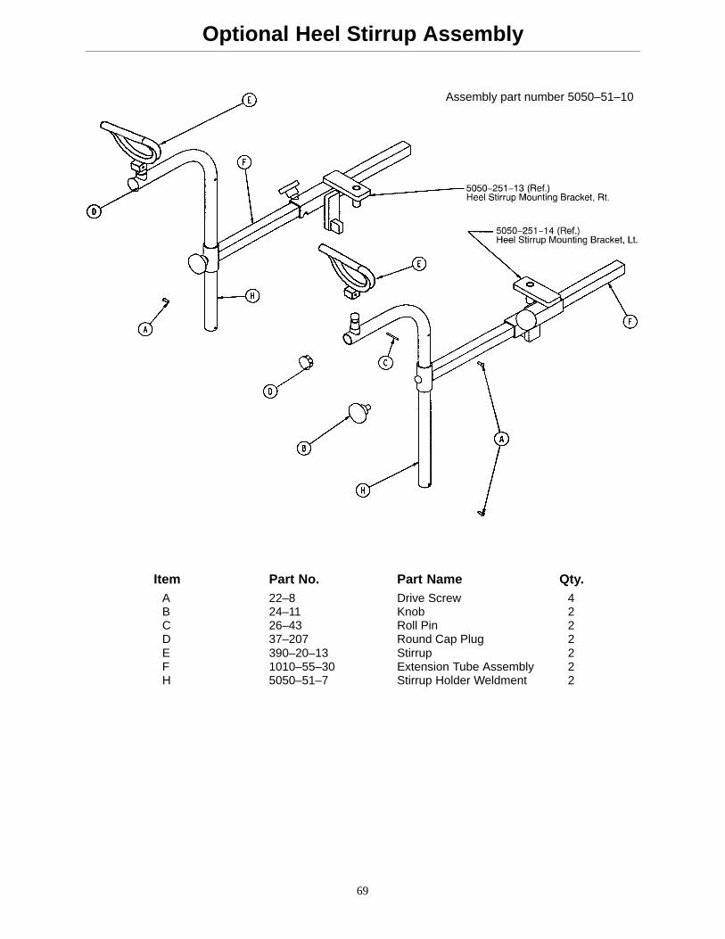
Optional Heel Stirrup Assembly
Assembly part number 5050–51–10
Item Part No. Part Name Qty.A 22–8 Drive Screw 4B 24–11 Knob 2C 26–43 Roll Pin 2D 37–207 Round Cap Plug 2E 390–20–13 Stirrup 2F 1010–55–30 Extension Tube Assembly 2H 5050–51–7 Stirrup Holder Weldment 2
70
Heel Stirrup Bracket Assembly
Assembly part number 5050–251–15
Item Part No. Part Name Qty.A 3–4 Hex Hd. Cap Screw 4B 16–16 Nylon Lock Nut 4C 24–11 Knob 2D 5050–251–3 Tube Support, Right 1E 5050–251–4 Tube Support, Left 1F 5050–251–13 Heel Stirrup Bracket, Rt. 1H 5050–251–14 Heel Stirrup Bracket, Lt. 1J 13–10 Ext. Tooth Lock Washer 4
71
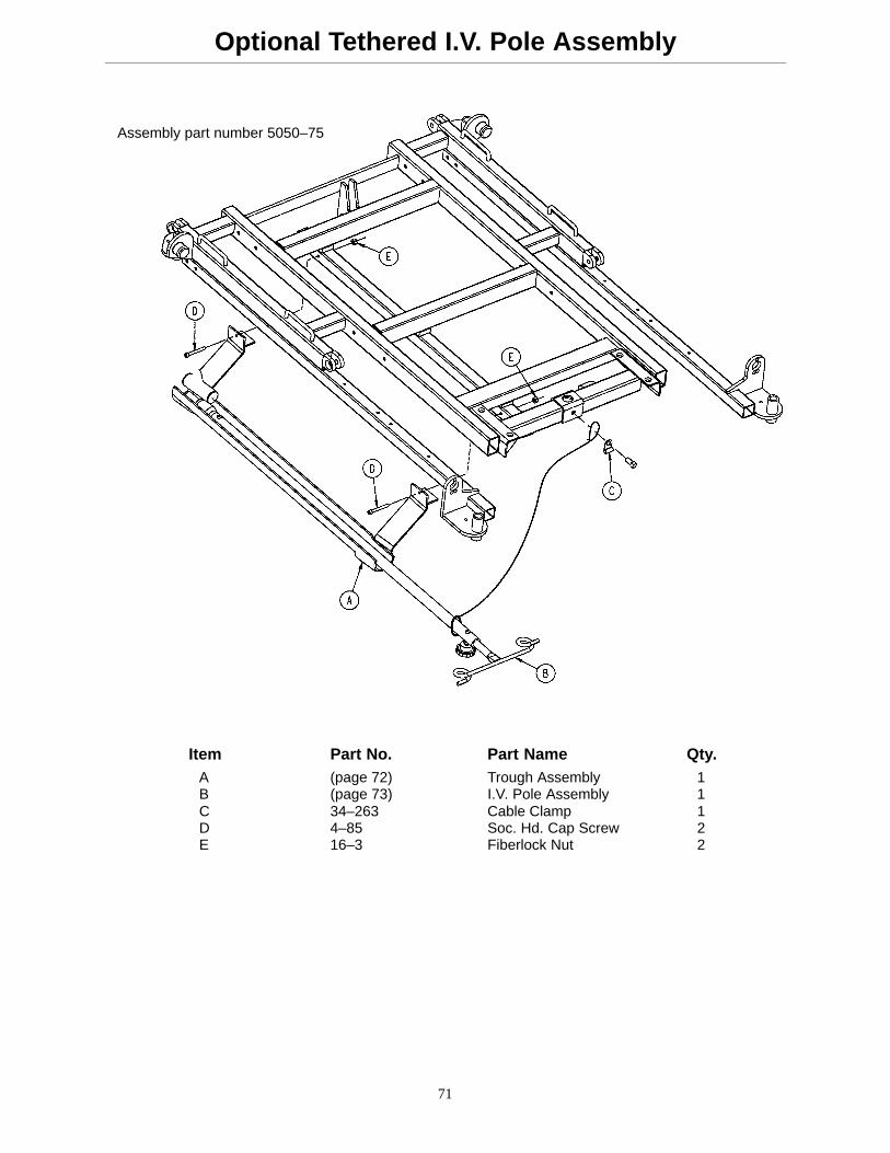
Optional Tethered I.V. Pole Assembly
Assembly part number 5050–75
Item Part No. Part Name Qty. A (page 72) Trough Assembly 1
B (page 73) I.V. Pole Assembly 1C 34–263 Cable Clamp 1D 4–85 Soc. Hd. Cap Screw 2E 16–3 Fiberlock Nut 2
72
Tethered I.V. Pole Trough Assembly
Assembly part number 5050–75–5
Item Part No. Part Name Qty.A 1001–87–23 Machined Sleeve 1B 5050–75–2 I.V. Bracket, Head End 1C 1001–87–15 Mounting Bracket Ass’y 1D 1–22 Flat Hd. Mach. Screw 2E 37–2 Tube Plug 2F 946–40–110 Lock Clip 1H 16–14 Hex Nut 2
73
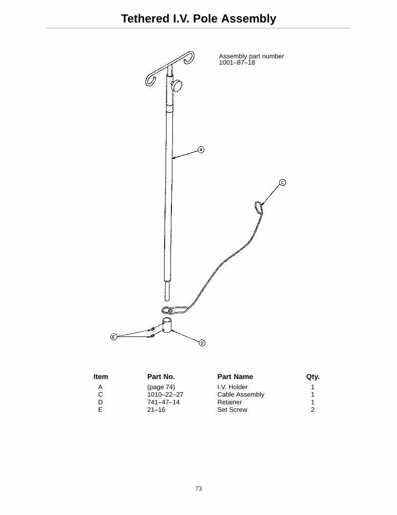
Tethered I.V. Pole Assembly
Assembly part number1001–87–18
Item Part No. Part Name Qty.A (page 74) I.V. Holder 1C 1010–22–27 Cable Assembly 1D 741–47–14 Retainer 1E 21–16 Set Screw 2
74
I.V. Holder Assembly
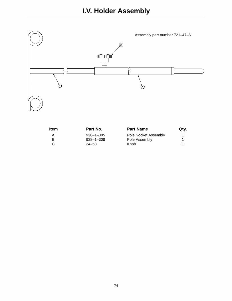
Assembly part number 721–47–6
Item Part No. Part Name Qty.A 938–1–305 Pole Socket Assembly 1B 938–1–308 Pole Assembly 1C 24–53 Knob 1
75
Wrist Rest Assembly
Assembly part number 1068–250–10
Item Part No. Part Name Qty.A 1068–250–42 Locking Wedge 1B 1068–250–41 Wedge Bolt 1C 14–3 Fiber Washer 1D 24–55 Knob, Male 1E 26–42 Roll Pin 1F 24–54 Knob, Female 1H 1068–290–50 Specification Label 1J 1068–250–50 Base Tube Weldment 1K 1068–252–55 Support Bar Weldment 1L 4–163 But. Hd. Cap Screw 1M 1068–50–55 Tube Weldment 1N 17–4 Acorn Nut 1
76
Wrist Rest Assembly, Temporal
Assembly part number1068–251–10
Item Part No. Part Name Qty.A 1068–250–42 Locking Wedge 1B 1068–250–41 Wedge Bolt 1C 14–3 Fiber Washer 1D 24–55 Knob, Male 1E 26–42 Roll Pin 1F 24–54 Knob, Female 1H 1068–290–51 Specification Label 1J 1068–250–50 Base Tube Weldment 1K 1068–252–55 Support Bar Weldment 1L 4–163 But. Hd. Cap Screw 1M 1068–51–50 Tube Weldment 1N 17–4 Acorn Nut 1
77
Wrist Rest Bracket Assembly
Assembly part number 5050–50
Item Part No. Part Name Qty.A 7–20 Truss Hd. Mach Screw 2B 16–16 Nylon Lock Nut 2C 5050–50–2 Mounting Bracket 1
78
Leg Support Assembly
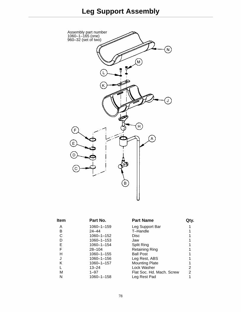
Assembly part number1060–1–165 (one)960–32 (set of two)
Item Part No. Part Name Qty.A 1060–1–159 Leg Support Bar 1B 24–44 T–Handle 1C 1060–1–152 Disc 1D 1060–1–153 Jaw 1E 1060–1–154 Split Ring 1F 28–104 Retaining Ring 1H 1060–1–155 Ball Post 1J 1060–1–156 Leg Rest, ABS 1K 1060–1–157 Mounting Plate 1L 13–24 Lock Washer 2M 1–97 Flat Soc. Hd. Mach. Screw 2N 1060–1–158 Leg Rest Pad 1
79
Leg Support Bracket Assembly
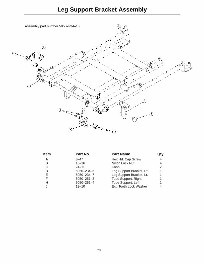
Assembly part number 5050–234–10
Item Part No. Part Name Qty.A 3–47 Hex Hd. Cap Screw 4B 16–16 Nylon Lock Nut 4C 24–11 Knob 2D 5050–234–6 Leg Support Bracket, Rt. 1E 5050–234–7 Leg Support Bracket, Lt. 1F 5050–251–3 Tube Support, Right 1H 5050–251–4 Tube Support, Left 1J 13–10 Ext. Tooth Lock Washer 4
Stryker Medical Division, a division of Stryker Corporation, warrants to the original purchaser that its productsshould be free from defects in material and workmanship for a period of one (1) year after date of delivery.Stryker ’s obligation under this warranty is expressly limited to supplying replacement parts and labor for, orreplacing , at its option , any product which is, in the sole discretion of Stryker, found to be defective. Strykerwarrants to the original purchaser that the frame and welds on its beds will be free from structural defectsfor as long as the original purchaser owns the bed. If requested by Stryker, products or parts for which awarranty claim is made shall be returned prepaid to Stryker’s factory. Any improper use or any alteration orrepair by others in such manner as in Stryker’s judgement affects the product materially and adversely shallvoid this warranty. No employee or representative of Stryker is authorized to change this warranty in any way.
Stryker Medical stretchers are designed for a 10 year expected life under normal use conditions and appropri-ate periodic maintenance as described in the maintenance manual for each device.
This statement constitutes Stryker’s entire warranty with respect to the aforesaid equipment. STRYKERMAKES NO OTHER WARRANTY OR REPRESENTATION, EITHER EXPRESSED OR IMPLIED, EXCEPTAS SET FORTH HEREIN. THERE IS NO WARRANTY OF MERCHANTABILITY AND THERE ARE NOWARRANTIES OF FITNESS FOR ANY PARTICULAR PURPOSE. IN NO EVENT SHALL STRYKER BELIABLE HEREUNDER FOR INCIDENTAL OR CONSEQUENTIAL DAMAGES ARISING FROM OR IN ANYMANNER RELATED TO SALES OR USE OF ANY SUCH EQUIPMENT.
To Obtain Parts and Service:
Stryker products are supported by a nationwide network of dedicated Stryker Field Service Representatives.These representatives are factory trained, available locally, and carry a substantial spare parts inventory tominimize repair time. Simply call your local representative, or call Stryker Customer Service at (800)327–0770.
Supplemental Warranty Coverage:
Stryker has developed a comprehensive program of extended warranty options designed to keep your equip-ment operating at peak performance at the same time it eliminates unexpected costs. We recommend thatthese programs be activated before the expiration of the new product warranty to eliminate the potential ofadditional equipment upgrade charges. Stryker offers the following Supplemental Warranties:
Extended (Parts and Labor)
� All replacement parts (excluding mattresses and consumable items)
� Labor and travel for all scheduled and unscheduled calls
� Annual Preventive Maintenance Inspections and repairs
� JCAHO paperwork for preventive maintenance
� Priority Emergency Service
Standard (Labor Only):
� Labor and travel for all scheduled and unscheduled calls
� Annual Preventive Maintenance Inspections and repairs
� JCAHO paperwork for preventive maintenance
� Priority Emergency Service
Basic (Parts Only):
� All replacement parts (excluding mattresses and consumable items)
� Priority Emergency Service
Please call your local representative, or call (800) 327–0770 for further information
Warranty
82
Return Authorization:
Merchandise cannot be returned without approval from the Stryker Customer Service Department. An autho-rization number will be provided which must be printed on the returned merchandise. Stryker reserves theright to charge shipping and restocking fees on returned items.
SPECIAL, MODIFIED, OR DISCONTINUED ITEMS NOT SUBJECT TO RETURN.
Damaged Merchandise:
ICC Regulations require that claims for damaged merchandise must be made with the carrier within fifteen(15) days of receipt of merchandise. DO NOT ACCEPT DAMAGED SHIPMENTS UNLESS SUCH DAMAGEIS NOTED ON THE DELIVERY RECEIPT AT THE TIME OF RECEIPT. Upon prompt notification, Strykerwill file a freight claim with the appropriate carrier for damages incurred. Claim will be limited in amount tothe actual replacement cost. In the event that this information is not received by Stryker within the fifteen(15) day period following the delivery of the merchandise, or the damage was not noted on the delivery receiptat the time of receipt, the customer will be responsible for payment of the original invoice in full.
Claims for any short shipment must be made within thirty (30) days of invoice.
International Warranty Clause:
This warranty reflects U.S. domestic policy. Warranty outside the U.S. may vary by country. Please contactyour local Stryker Medical representative for additional information.
DH 1/99 5050–90–25 REV J
European Representative
Stryker France Phone: 33148632290BP 50040–95946 Roissy Ch. de Gaulle Fax: 33148632175Cedex–France
6300 Sprinkle Road, Kalamazoo, MI 49001–9799 (800) 327–0770