English Operator’s Manual 2019- A428527 2019 2 EN 2018- Read this Operator’s Manual, safety decals, and other safety related instructions before operating the loader. If you do not obey these instructions, there is a risk of serious injury. Keep all manuals for reference. 523/528/530
Transcript
English
Operator’s Manual2019-
A428527 2019 2 EN 2018-
Read this Operator’s Manual, safety decals, and other safety related instructions before operating the loader. If you do not obey these instructions, there is a risk of serious injury. Keep all manuals for reference.
523/528/530
2
500 Series
TABLE OF CONTENTS
Original instructions
Table of contents
Introduction..................................................................3Safety instructions.........................................................4 Intended use............................................................4 Safety first...............................................................5 Handling of heavy loads...........................................6 Operation on gradients............................................8 Personal safety and protective equipment..............9 Safety frame (ROPS) and safety canopy (FOPS)......9 Electric system and handling the battery.................10 Fire prevention.......................................................10Warranty...................................................................11Description of the loader.............................................13 Loader identification..............................................13 Engine identification..............................................13 Main parts of the loader..........................................14 Signs and decals......................................................15 Technical specification...........................................19 Engine specification...............................................20 Fuel requirements.................................................20 Engine oil requirements........................................20 Tires....................................................................20 Auxiliary hydraulics oil flow....................................21Tipping load..................................................................22 Tipping load..........................................................22 Load diagram.........................................................22 Rated operating capacity........................................23Operating instructions................................................24 Operating controls................................................24 Control of loader boom, auxiliary hydraulics and other functions...............................25 Dashboard.............................................................26 Indicator lights.......................................................26 Seat belt and seat adjustments................................27 Air Suspension seat................................................27 Battery disconnect switch.....................................28 Controls in the footwell........................................28 Installing of service support and frame lock..........28 Drive speed range selection switch.......................29 Drive release valve.................................................29 Parking brake switch.............................................29 Anti slip valve.........................................................29 Loader control.......................................................30 Telescopic boom...................................................30 Boom floating........................................................30 Self leveling boom.................................................31 Smooth drive.........................................................31 Tilt adapter............................................................31 Using the auxiliary hydraulics................................32 Joystick with auxiliary hydraulics control buttons...32 Attachment control switch pack...........................32 Extra auxiliary hydraulics outlets, front and rear.....33 Work light kit........................................................34
Headlight, beacon, blinker & reflector kit.............34 Warning beacon....................................................34 Trailer coupling......................................................34 Extra counterweights............................................34 Hydraulic lifting device in the rear...........................34 Starting the engine.................................................35 Engine block heater...............................................35 Stopping the engine...............................................36 Drive control.........................................................37 Steering of the loader.............................................38 Requirements for attachments..............................39 Coupling the attachments.....................................40 Hydraulic attachment coupling plate.....................40 Coupling the hydraulic hoses of the attachment....41 Releasing the pressure of hydraulic system...........41 Transporting instructions and tie down points......42 Installing of frame lock...........................................42 Towing...................................................................42 Lifting...................................................................43 Storage of the loader..............................................43 Cabs LX and DLX.................................................44Maintenance and service............................................46 Safety instructions.................................................47 Maintenance of hydraulic systems..........................47 Daily inspections and Maintenance.......................48 Service, engine......................................................48 Service schedule....................................................49Daily inspections and maintenance...........................50 Refueling...............................................................50 General condition of loader...................................50 Cleaning of the loader..........................................51 Greasing of the loader..........................................52 Hydraulic oil level..................................................54 Attachment and its locking.......................................54 Engine oil level.......................................................55 Check coolant level...............................................55 Water in fuel..........................................................55 Air filter element...................................................55 Battery and electric cables....................................56 Drive control and steering.....................................56 Movements of boom.............................................56 Main fuses..............................................................57 Light bulbs.............................................................57 Hydraulic oil cooler fan fuse..................................57 Jump start and auxiliary power..............................57 Filters....................................................................58 Troubleshooting....................................................59Service history..............................................................60EC Declaration of Conformity....................................61
3
500 Series
Introduction
AVANT TECNO OY wants to thank you for purchasing this AVANT loader. It is the result of Avant’s long experience in design and manufacturing of compact loaders. We ask you that you read and understand the contects of this manual completely before operating the loader. This operator’s manual is intended to help you to:• operate this machine safely and efficiently• observe and prevent situations that may cause a risk or danger• keep the machine in good condition and its life span as long as possible
The following warning symbols and signal words are used throughout this manual to indicate factors that must be taken into account to reduce the risk of personal injury or damage to property:
Introduction
This signal word indicates a hazardous situation which, if not avoided, will cause death or serious injury.
This signal word indicates a potentially hazardous situation which, if not avoided, could cause serious injury or death.
This signal word is used when minor injury could result if the instructions are not followed properly.
This signal word indicates information about the correct operation and maintenance of the equipment. It is used without the safety alert symbol.Failure to observe the instructions accompanying the symbol can lead to equipment breakdown or other property damage.
WARNING:SAFETY ALERT SYMBOLThis symbol means: “Warning, be alert! Your safety is involved!”
This safety symbol refers to important safety information in this manual. It warns of an immediate hazard that could cause serious personal injury to yourself or others near the equipment.
The safety alert symbol by itself and with related safety statement indicates important safety messages throughout this Manual. It is used to draw attention to instructions involving your personal safety or the safety of others. When you see this symbol, be alert, your safety is involved, carefully read the message that follows, and inform other operators.
DANGER
WARNING
CAUTION
NOTICE
4
500 Series
In addition to this Operator’s manual of the loader, ensure that you have received and read also the original Engine owner’s manual. The instructions concerning the engine must be followed. If conflicting information is found, the information shown in the Operator’s Manual of the loader must be followed.
Each attachment is accompanied by its own respective Operator’s Manual. The manual will show important information related to safety, and how to attach, use, and maintain each attachment correctly.
Intended use
AVANT 523/528/530 is an articulated compact loader, designed and manufactured for both professional and private use. The loader can be equipped with attachments offered by Avant Tecno Oy, which enables doing of several different jobs. Because of this multi purpose nature of the machine and the various attachments and tasks, read always not only this Manual but also the Operator’s manual of the attachment, and follow all instructions. Every person who has to do with this machine must follow work safety regulations, all other generally accepted rules related to work health and safety, and all road traffic regulations.
Remember that safety consists of several factors. The loader, equipped with an attachment is very powerful and can cause serious personal injuries or property damages if it is operated in a wrong or careless way. Do not operate an attachment unless you have familiarised yourself with the use of it and the eventual dangers related to it.
This loader has been designed to require as little maintenance as possible. The operator can perform the routine maintenance operations. There are however more demanding service operations that can be done by professional service personnel only. It is allowed to perform service operations only when wearing appropriate protective equipment. Original spare parts must be used. Familiarise yourself with the service and maintenance instructions in this Manual.
Contact your local AVANT dealer, if you are uncertain of anything concerning the operation and maintenance of this loader, or for any questions, service or spare parts.
Make sure all relevant manuals are available
Wrong use of the equipment can cause death or severe injuries - Make sure to read all relevant manuals and instructions thoroughly and keep them available for all operators.
Using each attachment requires specific information about correct use, mounting procedure, safety, and how to avoid hazardous situations. An attachment may introduce risks that are not present when operating the loader with other kinds of attachments. Always read the operator’s manual of each attachment carefully.
Contact your local AVANT dealer for any questions, service, spare parts or about any problems that may occur with the operation of your machine.Keep this Operator’s manual with the machine at all times. If this Manual gets lost, ask for a new copy from your Avant dealer. Remember also to give this Manual to the new owner when the machine changes ownership.
Safety instructions
DANGER
DANGER
5
500 Series
Safety first
Incorrect or careless operation of the loader may cause a serious accident. Before putting the machine into operation, familiarise yourself with the use of the machine and read and understand this Operator’s Manual, as well as all relevant safety instructions, local regulations, and safe working practices.
Understand the limitations of speed, braking, steering and stability as well as loading capacity of the machine before starting operation. Make sure that everyone who operates or works with this equipment is familiar with these safety precautions. If you have no previous experience of the machine, make sure to do all testing at a safe and open place with no persons in the area of operation.
Read this Operator’s manual, and also the Operator’s manual of the attachment(s), the engine owner’s manual, safety decals and other safety instructions before beginning to operate the loader. Failure to follow the safety precautions listed in this manual may result in personal injury and/or damage to the equipment.
1. Remember the correct working position. When driving, be comfortably seated in the driver´s seat, keep your feet in their proper place in the footwell and at least one hand on the steering wheel.
2. When seated, always keep the seat belt fastened and keep hands and feet inside the operator’s area.
3. Before leaving driver’s seat, always:• Lower the loader boom and place attachment flat
on ground• Engage the parking brake• Stop the engine, remove the ignition key
4. Start the operation slowly and carefully. Practise driving of the machine at a safe and open place before connecting any attachment, and follow the instructions in this Manual and also the operator’s manual of the attachment.
5. Operate the control levers with careful and deliberate movements. Avoid abrupt movements when handling the load, in order to prevent the load from falling and to keep the machine stable.
6. Keep away from the danger zone of the lifted boom and don’t let anyone go there.
7. Keep your hands, feet and clothing away from all moving parts, hydraulic components, and hot surfaces.
8. Make sure that there is enough open space around the loader and its attachments for safe driving and use of the attachments
9. Do not transport the load with the boom lifted. Always carry bucket or attachment as low as possible, and put the load down whenever you leave the machine.
10. It is not allowed to transport persons with this machine. Do not transport or lift persons in the bucket or in any other attachment.
11. Do not exceed the tipping load. Familiarise yourself with and follow the load diagrams in this Manual.
12. When turning with the machine, remember that the driver´s seat extends beyond the turning radius of the wheels (collision risk).
13. Do not operate the loader in an explosive environment or in a place where dust or/and gases can create a fire or explosion hazard.
14. Keep the engine area clean of flammable materials.
15. Read the lifting, towing and transportation instructions on page 42.
16. Switch off the battery disconnect switch whenever leaving the machine unattended.
17. Follow all inspection, service and maintenance instructions. If you notice any faults or damages on the machine, these must be repaired before starting operation.
18. Before any maintenance or repair operation always stop the engine, lower the boom down and release pressure from hydraulic system. Read safety instructions for maintenance on page 46.
19. Do not let any person operate this loader who has not read safety instructions and is not familiar with the safe and correct use of this loader.
20. Never operate the loader or attachments while under the influence of alcohol, drugs, medication that may impair judgement or cause drowsiness, or if not otherwise medically fit to operate the equipment.
Safety instructions
General safety instructions - Always follow all instructions to avoid personal injury
DANGER
6
500 SeriesSafety instructions
Falling of load or unexpected lowering of loader boom - Risk of crushing. Always remember that the boom may lower unexpectedly due to loss of stability, mechanical fault, or if another person operates the controls of the loader, leading to crushing hazard. The attachment or the loader are not intended to be left to keep a load elevated for longer periods. Lower the attachment before leaving the driver’s seat. The stability of the loader may change when leaving the driver’s seat, leading to tipping over of the machine.
Falling of persons - Risk of crushing. Never use the loader or its attachments to lift persons or as any kind of work platform even temporarily. Never climb on the loader or on the attachment. Seating capacity: one person only, regardless of attachment.
Risk of falling objects - Make sure load is securely on the attachment. Never tilt an attachment back when it is lifted high. Make sure the loader is equipped with ROPS and FOPS structures that are in good condition and do not have visible damage. Make sure the attachment is properly locked.
Hydraulic pressure - Risk of injury. Escaping hydraulic fluid under pressure has sufficient force to penetrate skin, causing serious personal injury. Never use hands to search for possible leaks in hydraulic systems - use a piece of cardboard instead. Release residual hydraulic pressure before disconnecting any fitting and before any service operation. See a physician immediately if hydraulic fluid penetrates skin, serious injury can result quickly.
Risk of being crushed by moving loader - Engage parking brake before working near the loader. Follow safe stopping procedure to prevent all movements of the loader. Avoid leaving the loader parked on hill. If necessary to park on hill, use chocks or other additional means to prevent the loader from moving.
Safety devices are installed for your safety - Never modify or bypass any safety function. Safety functions are installed for your safety. Never modify or block any of the safety systems of the loader. If you notice that a system is not in good condition, stop the use of the loader and make sure the is serviced.
DANGER
DANGER
WARNING
WARNING
DANGER
WARNING
7
500 Series Safety instructions
Pinching points - Avoid pinching between loader frame itself and between loader and walls - Keep all body parts within the safety frame. Movements of the articulated frame creates pinching hazards. Keep your head, hands, and feet inside the loader. Be especially careful while you drive near walls and trees. Keep your hands on steering wheel and joystick.
Avoid pinching hazard for legs - Do not turn the steering wheel while standing near the loader. Turning the articulated frame creates a pinching hazard to a person standing near the tyres of the loader. Never grab the steering wheel while entering or leaving the driver’s seat to avoid turning of the frame. Stop the loader if other persons get close to it. Check that tyres that are larger than standard tyres leave enough space between the tyres for safe use.
Handling of heavy loads
Handle loader with care - Risk of tipping over.• Follow all instructions and warning
labels to avoid tipping over of the loader.
• Always put the load down on the ground before you leave the driver’s seat.
• Keep loads as low and as close to the loader as possible.
• When loading, always keep the loader frame as straight as possible.
• Never drag a heavy load with the loader from high level – e.g. from truck, shelf etc.
• Always handle heavy loads only on firm, level ground, while you drive slowly with the machine.
- Uneven or inclined terrain significantly reduces the safe working load, (see also page 23.)
- Use the maximum loads indicated in the diagram in this manual as a guideline.
- All rated operating capacities are based on the criteria of the machine is level on a firm supporting ground. When the machine is operated in conditions that deviate from these criteria (e.g. on soft or uneven ground, on a slope or when subject to slide loads), you must take these conditions into account.
- Remember that the actual load carrying capacity varies greatly according to operating conditions and control manner.
- Be especially careful when the load sensor indicator is activated. See page 23 for more information about the load sensor.
• Keep the articulated frame of the loader in straight position when you lift heavy loads. If you turn the loader during load handling, the stability of the loader will decrease and it may overturn the machine.
• The use of extra rear weights or ballasted tires is recommended. See page 34 for different options.
• Make sure to follow the recommended tire pressures.• Pay attention that a heavy load or long distance between
the loader and the center of gravity of the load will affect the balance and handling of the loader.
• When you estimate the lifting capacity of the loader, remember to take the weight of the attachment into account.
WARNING
CAUTION
WARNING
8
500 SeriesSafety instructions
Whenever you handle heavy loads or heavy attachments:
Overload - Risk of overturning.The high lift capacity of the loader makes it possible to exceed the stability of the loader when handling loads. Read the instructions regarding maximum lift capacity and load handling in this Operator’s Manual. Following the instructions reduces the risk of tipping the machine over its front axle, but the operator must be aware of the limits of the machine and follow safe working practises to avoid overturning of the machine.
Articulated frame - Risk of overturning. Turning articulated frame can lead to overturning of the loader on inclined terrain or when driving at high speed. Never turn frame towards the slope while operating on inclined ground. Always drive slowly when carrying load or when turning with the machine.
Sudden movements can tip the machine over - Risk of overturning. Movements, such as stopping, turning, or lowering the boom abruptly, can cause loss of stability. Always drive slowly and operate the controls of the loader very carefully, especially when handling heavy loads.
In case the loader tips over :
Avoid tipping over of the loader with careful operation and the instructions given throughout this manual. However, it is important to know what to do in case the machine tips over.
Risk of being crushed by the ROPS structure in case the laoder tips over - Always use the seat belt and stay within the space protected by the ROPS safety frame.Always keep seatbelt on to stay on driver’s seat and to avoid getting crushed between ground and a loader that tips over.
In case the loader tips over: Switch off the engine of the loader immediately. Running the engine and pumps of an overturned loader will damage them quickly and will spill hydraulic oil and fuel. As soon as possible, lift the loader back on its wheels to prevent spilling of fuel and oils. The loader can in many cases be lifted back on its wheels by having a few persons to lift it from the ROPS frame. Engine oil can leak inside the engine, causing major engine damage if the engine is attempted to be restarted after the loader has been overturned. Contact service before you attempt to restart the engine.
WARNING
WARNING
CAUTION
NOTICE
WARNING
9
500 Series Safety instructions
Operation on gradients
Load, unload, and turn on flat level ground only. Drive slowly on uneven terrains. Do not drive on too steep a gradient - watch out for ditches, manholes and steep gradients.
Do not park the machine on a surface with a gradient. Should this be necessary, engage the parking brake and preferably turn the machine sideways and put down the load. If needed, use chocks behind the wheels.
Use low speed range when driving on hills or uneven terrain.
Risk of tipping over - Always keep loads close to the ground. The stability and the load handling capacity of the loader are significantly reduced on inclined terrains and Maximum lifting capacity can be achieved only on firm, level ground. On horizontally tilted terrain the load must be kept close to the ground and must never be lifted high.
Suffocation hazard - Ensure ventilation
Engine exhaust contains carbon monoxide (CO), a poison gas you cannot see or smell. Using a loader in enclosed space or poorly ventilated areas will kill you in minutes.
Never operate the loader indoors or in partly enclosed areas unless you’ve made sure there is special ventilation system installed. Loaders with a combustion engine produce, among other pollutants, carbon dioxide (CO2) and can also emit carbon monoxide (CO) under some conditions that can concentrate quickly to a dangerous level. Never leave the engine running in garages or sheds. Operate the loader only outdoors and far from windows, doors, and vents.
Elevated level of carbon dioxide or carbon monoxide in breathing air can not be noticed without dedicated measuring equipment. Signs of carbon monoxide poisoning include nausea, headache, dizziness, drowsiness, and lack of consciousness.
Get fresh air if anyone shows signs of carbon monoxide poisoning and see a physician.
Diesel exhaust also contains other chemicals that are harmful. Prolonged exposure to exhaust fumes should be avoided. Ventilate indoor spaces well e.g. after starting a loader. The odor or colour of diesel exhaust does not tell if there are dangerous levels of carbon dioxide or carbon monoxide in the breathing air.
DANGER
DANGER
10
500 SeriesSafety instructions
Personal safety and protective equipment
Wear safe clothing and personal protective equipment.
• Protect yourself against work hazards like noise,ejecting debris or dust for example.
• Follow regulations regarding protective equipment. Wear eye protection and hard hat or other protective equipment as needed.
• Read Operator’s Manual of the attachment for more information about protective equipment needed in the work.
• The noise level at the driver’s seat may exceed 85 dB (A). Wear hearing protection while working with the loader.
• Wear protective gloves.
• Wear safety boots whenever working with the loader.
• Wear safety glasses when handling hydraulic components.
• Always fasten seat belt while operating the machine.
• When working at construction sites, a hard hat is recommended and may be mandatory in addition to the falling objects protective structure (FOPS) on the loader.
• Depending on work and working area, also a respirator mask maybe required. Find out about other necessary safety equipment at your specific work site.
Silica dust warning. Prolonged exposure to crystalline silica can cause a lung disease called silicosis. Occupational health and safety officials recommend limiting exposure to dust that is present at most earth-moving and many other work sites. Avoid spreading of dust where possible, keep loader cabin clean from dust, use respiration mask when necessary.
Safety frame (ROPS) and safety canopy (FOPS)
The loader is equipped with a Rolling Over Protective Structure (ROPS) and a Falling Object Protective structure (FOPS). These safety structures are important parts of operator safety, and they must be fitted on the machine.
Safety frame (ROPS) protects the operator in case the machine tips over. Fasten seat belt while operating a machine with a ROPS. All cab versions are ROPS & FOPS tested and certified.
Never remove the safety structures, modify them, or attempt to repair. If damaged, contact service. Always fasten the seat belt in order to stay inside the protected area of the safety frame.
Understand the limitations of the Falling Object Protective structure (FOPS). The loader is equipped with a Level 1 FOPS, which gives protection against moderate impacts.
Modifications
Any modification to this machine must be approved beforehand by an authorised Avant representative. If you modify the loader or attachment, it can become dangerous and cause serious injuries or even death. Unauthorised modifications can increase the risk of accidents and damage or shorten the service life of the machine. Modifications to engine can make it no longer compliant with emission regulations. Use only original spare parts to make sure that the product is kept in safe operating condition.
CAUTION
WARNING
11
500 Series Safety instructions
Electric system and handling the battery
Always handle the battery with care. Follow the safety instructions given below. The battery of the 12 V electric system of the loader is located at the rear of the loader, on the right side of the engine. See page 56 for more information about battery and maintenance instructions.
Short-circuit of the battery can create fire or explosion. Disconnect the battery with the battery disconnect switch before working on the engine or equipment. Never lay metal objects on the battery. Keep the top surface of the battery clean.
Battery acid can cause severe skin burns. Handle damaged battery with extreme care and wear appropriate safety gloves and clothing. Battery is a sealed type battery, meaning that you should never attempt to open the battery.
Lead acid batteries produce flammable and explosive gases during charging. Make sure that ventilation is sufficient when charging the battery. Keep arcs, sparks, flames, and lighted tobacco away from battery. Never charge a frozen battery. A frozen battery can explode during charging.
Battery and its terminals contain lead, a harmful substance which should not be handled more than what is necessary. Wash hands with soap and water after handling the battery.
Whenever you handle the battery, keep the following in mind:
• Battery contains corrosive sulphuric acid which causes serious burns upon skin contact. Avoid contact with skin or clothes. If electrolyte gets on your skin or clothes, flush with a lot of water. In case of contact with eyes, flush with a lot of water for at least 15 minutes and see a doctor immediately.
• In order to avoid spark emissions, always disconnect the negative (-) cable first and connect it last.
• Before connecting the battery cables make sure that the polarity is correct: Faulty connection will seriously damage the electric system of the engine and may cause sparks, fire, or even explosion of the battery.
• If a fuse is blown repeatedly, find out the cause. Always use fuses with correct rating.
• Read the instructions for jump start, see page 58
Fire prevention
Clean the loader to avoid build-up of flammable debris, such as dust, leaves, hay, straw, etc.
• There are many parts of the diesel engine that operate at high temperatures in normal use. To avoid fire, and to ensure that the cooling is ensured, keep the engine and engine bay clean. Overheating of the engine can shorten its service life.
• Do not smoke during refueling or during any inspection or maintenance work.
• Add fuel and oils only at a well ventilated place.
• Oil and fuel leaks can ignite on hot components. Repair any damaged or leaking components before using loader. Refuel and add oil only after the loader is cooled down.
• The battery produces hydrogen gas during recharge. This gas can cause fire or explosion, if charging of the battery is not made correctly. Charge battery in a well ventilated place, and keep sources of ignition away from battery during recharge. Static electricity can produce sparks when removing plastic cover, avoid handling or cleaning of plastic covers when battery is connected to a charger.
Know where fire extinguishing equipment is located near your working site. At some areas a fire extinguisher may be mandatory. Keep a multi-purpose, approved type fire extinguisher available near the place where you store the loader.
To prevent the risk of fire, always disconnect the battery with the battery disconnect switch. See page 28 for more information about the battery disconnect switch.
Risk of fire - Always switch off main current when the loader is not used. Turn the battery disconnect switch to position OFF whenever leaving the loader unattended or before servicing the machine. If left on, there is a risk of sparks and short-circuit during maintenance and if any electric insulator is faulty.
WARNING
WARNING
WARNING
CAUTION
WARNING
12
500 Series
Avant 523/528/530 warranty
This warranty specifically applies to the AVANT 523/528/530 loader only and not to any attachments used with this product. Any repairs or modifications performed without the prior authorisation of Avant Tecno Oy will cancel this warranty.During the first two years of operation or first 1000 hours (whichever is the soonest) Avant Tecno Oy warrants to replace any part or repair any defect which may occur, subject to the terms detailed below:1) The product has received regular maintenance in accordance with schedules given by the manufacturer.2) Any damage caused by operation in a negligent manner or exceeding the approved specifications detailed in this
manual is excluded.3) Avant Tecno Oy accepts no responsibility for interruption to working or any other consequential losses resulting from
any failure of the product.4) Only Avant Tecno Oy approved replacement or original quality parts shall be used during routine maintenance.5) Any damage caused by the use of incorrect fuel, lubricants, cooling liquid or cleaning solvents is excluded.6) The Avant Warranty excludes any consumable parts (e.g. tires, batteries, filters, belts etc.) except where it can be
clearly shown that these parts were defective on original supply.7) Any damage caused resulting from the use of attachments not approved for use with this product is excluded.8) In the event a fault occurs which is attributable to manufacturing or assembly defect you should arrange to return
your AVANT to your authorised dealer for repair. Travel and freight costs are excluded.
Warranty
13
500 Series Description of the loader
Description of the loader
Identification of the loader
Write down the identification information of your loader in the following fields, it facilitates ordering of spare parts etc.
2. Loader serial no.___________________________________________
3. Engine serial no.___________________________________________ Serial number of the loader is printed on the type plate, which also indicates the loader model.Location of engine serial number can be found in the Operator’s manual of the engine.
Loader identificationLoader identification plate is located near the steering wheel on machines with ROPS canopy and cab L, and near the drive pedals on machines equipped with a cab LX or DLX.
Engine identificationEngine identification plate is located on the valve cover.
14
500 SeriesDescription of the loader
Main parts of the loader
Following picture shows the main parts of the loader:
jk
l
m
no
p
q
j
k
l
m
Front frameOn the front frame are mounted: driver’s seat, operating controls, hydraulic control valves, hydraulic oil tank, auxiliary hydraulics outlet, front wheels, hydraulic motors and the loader boom with attachment coupling plate.
Back frameOn the back frame are mounted: engine with accessories, battery, parking brake, fuel tank, hydraulic pumps, rear wheels, hydraulic motors, counterweights.
Articulation jointArticulation joint connects the front and back frame. The loader is steered hydraulically by the steering cylinder which is mounted between the front and back frames. Hydraulic hoses and electric wires are conducted through the articulation joint.
Loader boomLoader boom is mounted on the front frame with a pivot pin. The attachment coupling plate is mounted on the lower end of the boom. The boom is telescopic, extending 600 mm hydraulically.
n
o
p
q
Attachment coupling plateAttachments are mounted on the attachment coupling plate. The locking pins on the plate can be operated manually (standard) or hydraulically (option).
Auxiliary hydraulics outletThe hydraulic hoses of hydraulically operated attachments are mounted on this outlet. The outlet is equipped with the multi connector quick coupling system and is double acting: it has two pressure lines and one tank line. Also the optional attachment control switch pack socket is mounted on the multi connector. In addition, as an option, it is also possible to install a single or double acting auxiliary hydraulics outlet in the rear of the machine, or a double acting outlet in the front under the multi connector.
ROPS safety frameROPS frame (Roll-over protective structure) complies with the standard ISO 3471:1994 with Amendment 1:1997 and Technical Corrigendum 1:2000.
FOPS canopyFOPS canopy (Falling objects protective structure) mounts on the ROPS. It meets the ISO 3449:2005 FOPS level 1 (1365 J) criteria.
HydraulicconnectorsMulti connector
Tank line Attachment control switch pack socket (option)
Pressure 2Pressure 1
15
500 Series Description of the loader
Signs and decals
Shown in the figure below and listed on the following page are the labels and markings, which must be visible on the equipment. Replace any warning label which has become unclear, or has detached completely. New labels are available via your Avant dealer, authorized Avant service point, or contact information provided on the cover.
Before applying a new decal, clean the surface from dirt, dust, grease, or other material. Peel small portion of the decal backing paper and apply exposed adhesive to cleaned surface, aligning the decal properly. Peel rest of backing paper and press with hands to smooth out the decal.
The warning labels contain important safety information and they help to identify and remember the hazards related to the equipment. Make sure that the following signs and decals are clean, undamaged and readable. If any of these decals is missing or is unreadable it should be replaced without delay. Ask for new decals from your local Avant dealer.
10
11
89
7
4
6
1
2
WARNING
16
500 SeriesSafety decals
Label Location Product code
Safety message
1
On panel below the steering wheel.
A417277
WARNINGTO AVOID INJURY OR DEATH:• Read operator’s manual before using
or servicing this machine. Follow all additional safety procedures, warning labels and attachment operator’s manual.
• Wear hearing protection and other proper personal safety gear called for by job conditions. Do not wear loose clothing while operating or servicing machine.
• Always use seat belt. Never carry passengers.
• Always perform a daily inspection of the machine before starting operation.
• Operate any machine control or steering wheel only when sitting on the driver’s seat.
• Keep hands, feet and clothing away from any moving part.
• When coupling an attachment, make sure that the locking pins of the attachment coupling plate lock properly down in the holes of the attachment.
• Follow safe stopping procedure or instructions provided in the operator’s manual of the attachment before leaving driver’s seat.
2Boom, on both sides
A417273 (2 pcs)
DANGER
Lowering of loader boom can crush, causing death or serious injury. Keep out from the danger zone of the ma-chine.
3
Onengine A417270
WARNING
Risk of burns - Extremely hot surfac-es. Keep clear.Allow loader to cool complet ely be-fore maintenance.
17
500 Series Safety decals
Label Location Product code
Safety message
4
At loader entry point A411455
WARNING
Risk of crushing - Small gap between tyres of articulat ed loader. Do not grip the steering wheel from outside the machine or when getting into the driver’s seat to prevent moving of the wheels.
5
At loader entry point A411456
WARNING
Risk of crushing - Keep hands and feet within the driver’s area.
18
500 SeriesSafety decals
Label Location Product code
Safety message
6ROPS frame A420726 ROPS/FOPS Approval
7
Right panel near driver’s seat
A43600 Sound pressure level 88 dB(A) at driver’s seat
8
Right panel near driver’s seat
A411047 Sound power level 101 dB(A) according to the European directive 2000/14/EC
9
Front panel below driver’s seat
A415780 Correct type of hydraulic oil
19
500 Series Technical specificationTechnical specification
*) Load is measured at 400 mm from the attachment coupling plate, including attachment weight ( 70 kg ) and with counterweights.
Height with cab 23x10.50-12 26x12.00-12 320/60-12 27x8.50-15
L Cab 2020 mm 2035 mm 2048 mmLX Cab 2010 mm 2025 mm 2038 mmDLX Cab 2030 mm 2045 mm 2058 mm
DLX Cab with Lightbar 2226 mm 2241 mm 2254 mm
Model AVANT 523 AVANT 528 AVANT 530Length 2440 mm 2570 mm 2570 mmWidth see table see table see table Height 1985 mm 1985 mm 1985 mmWeight 1200 + 170 kg 1250 + 170 kg 1290 + 170 kgStandard wheels 23x10.50-12” grass/TRTransmission, drive hydrostatic hydrostatic hydrostaticPulling force 900 kp 950 kp 1050 kpDrive speed 12 km/h 12 km/h 19 km/hHydraulic oil tank capacity 36 l 36 l 36 lHydraulic oil type ISO VG 46 ISO VG 46 ISO VG 46Auxiliary hydraulics oil flow / pressure 34 l/min 185 bar 36 l/min 200 bar 36 l/min 200 barTurning radius inside/outside 995 / 2050 mm 995 / 2050 mm 995 / 2050 mmMax. lifting height 2790 mm 2790 mm 2790 mmMax. lifting capacity (hydr.) 1350 kg 1500 kg 1500 kgMax. tipping load* 800 kg 950 kg 950 kgMax. breakout force / 50 cm 1100 kg 1250 kg 1250 kgSound pressure level 2000/14/EC LP 87 dB (A) 81 dB (A) 81 dB (A)Sound power level 2000/14/EC LW 100 dB (A) 96 dB (A) 96 dB (A)Hand-arm vibration, total < 2,5 m/s² < 2,5 m/s² < 2,5 m/s²Whole-body vibration, max. < 0,5 m/s² < 0,5 m/s² < 0,5 m/s²
1030 -1290 mm
1985
mm
2440 - 2570 mm790 - 920 mm 1220 mm 430 mm
2790
-282
0 m
m23
05 -
2335
mm
200
mm
600
mm
20
500 SeriesTechnical specification
Fuel requirementsDiesel fuel must meet the Ultra low sulfur diesel fuel requirements. Never add petroleum or any additives to diesel fuel.To comply with emissions standards, use only ULSD fuel with sulfur content less than 15 ppm / 0,0015 %.
Engine oil requirements Use only high quality engine oil with the viscosity rating recommended by the engine manufacturer with API service class SJ or higher. See also Kubota Operator’s Manual. In cold conditions use high quality multi grade oil.
TiresThe loader can be equipped with different type of tires for different operating conditions. Grass pattern (GR) tires will damage the ground surface less than tractor (TR) tires, but provide less traction.
For the best stability and controllability, always use the largest tires possible. Tires that are narrower than the standard tires are intended for special purposes only with width restriction on the machine. Use only tires and rims that meet the original specifications and dimensions to avoid potential issues with load capacity, tire size, or bearing load on drive motors. Consult your dealer if further information is needed. Special tires, such as studded wheels may also be available. Consult your dealer for further information.
Engine specification
��������������������
Model 523 528 / 530Engine make and type Kubota D902 Kubota D1105Function 4-stroke 4-strokeCoolant Water WaterNumber of cylinders 3 3Starter electric electricBore x stroke 72 x 73,6 mm 78,0 x 78,4 mmDisplacement 898 cm³ 1124 cm³Output (ECE R120) 16 kW (22 hp) 19 kW (26 hp)Fuel diesel dieselFuel tank capacity 20 l 30 lEngine oil type API CC API CCViscosity SAE 10W-30 SAE 10W-30Engine oil capacity 3,7 l 5,1 lCharging current max. 40 A 40 A
Tyres Tread pattern
Code Pressure Machine width Fits with fenders Front Rear
Fits with snow chains
27x8.50-15 TR 65414 2,5 bar 1030 mm - - 6572323x8.50-12 GR 65994 2,0 bar 1080 mm x x 6445523x8.50-12 TR 65995 2,0 bar 1080 mm x x 6445523x10.50-12 GR 65996 2,0 bar 1130 mm x x 6474523x10.50-12 TR 65997 2,0 bar 1130 mm x x 6474526x12.00-12 GR 65212 2,0 bar 1290 mm x x 6497326x12.00-12 TR 65739 2,0 bar 1290 mm x x 64973320/60-12 TR 65224 2,0 bar 1290 mm x x 65603
21
500 Series Technical specification
Auxiliary hydraulics oil flow The graph under shows auxiliary hydraulics output flow at different engine rpm levels. Some attachment may work optimally at certain flow level, use the graph to estimate correct engine rpm setting.
Maximum auxiliary hydraulics oil flow can not be used with all attachments. Check correct engine rpm and auxiliary hydraulics oil flow of the loader with the help of this graph and the Operator’s manual of the attachment.
NOTICE
523
528 / 530
�
�
��
��
��
��
��
��
��
����
����
����
����
����
����
����
����
����
����
����
����
����
����
����
����
����
����
����
����
����
����
���
�����
��������������������
22
500 Series
Tipping load
Tipping load is the load at which the rear tires lose contact with the ground (tipping forward). Tipping load is influenced by several factors:
• The total load on the loader boom (attachment weight and load combined)
• The distance of the load from the front tires• Straight or articulated position of the loader frame• Levelness of the ground• Installed counterweights• Driver presence• Movements of the loader and the load
Overload will cause the loader to tip forward. Always pay attention to safe operating conditions whenever lifting loads or handling heavy attachments.
The lifting capacity and the stability of the loader are at the best, when:• the loader frame is kept straight• the centre of gravity of the load is as close to the loader
as possible• counterweights are fitted to the loader• swinging of the load is prevented and all controls are
used in a calm and careful manner
Example: If the centre of gravity of the load is 750 mm in in front of the front axle (400 mm from the pallet forks at ground level), the tipping load is about 700 kg (523) and 820 kg (528/530) with a driver weighting 75 kg and with the articulated frame turned to max articulation.
If you leave the loader, tipping and max. loads are reduced respectively. The indicated load is the maximum load that can be loaded on pallet forks and the machine will not tip over, i.e. the weight of the standard pallet fork attachment (90 kg) is taken into account.
Load diagram
You can evaluate the load handling capability of the loader with the load diagram, shown below, and the Rated operating capacity shown on the next page and on the label on the loader.The load handling capability depends on the distance between the centre of gravity of the load and the front axle of the loader.The diagram represents the forward stability only, it does not refer to maximum available lift force.
The load diagram below shows the tipping loads on a level surface:a) Tipping load with the loader frame in straight position.
b) Tipping load with the loader frame in maximum articulation.
• ROC (Rate operating capacity), defined as 60 % of tipping load for pallet forks.
Avoid overloading the loader - know the load and lifting capacity of the loader. The diagram is valid only on firm and level ground, with the conditions listed above.
Tipping load
Tipping load
Tipping load with the loaderIn max. articulationRear weight 170 kgDriver 75 kg
Distance from front axle mm
Rated operating capacity (ROC)The loader In max. articulationRear weight 170 kgDriver 75 kg
528/530 523
528/530
523
CAUTION
WARNINGWARNING
23
500 Series
Rated operating capacity
To determine how much the loader can handle safely, a table of the tipping load and a calculated Rated Operating Capacity (ROC) is shown in the adjacent label.
A rated Operating capacity label is located near the driver’s seat and can be read while you sit on the driver’s seat.
Rated operating capacity depends on type of use of the loader:
• In bucket and general application the rated operating capacity is 50% of tipping load
• In pallet fork application the rated operating capacity is 60% of tipping load
The information shown in the table is the worst case minimum load, with the conditions listed below. Actual lifting capacity could be significantly higher, or it may be lower, depending on terrain conditions, available lifting force, and load distribution. Adding or removing counterweights will affect the indicated ROC.
The ROC table is valid, when:• The ground is firm and level• Loader is stationary or driven max 2 km/h, with smooth
and slow control movements• Driver 75 kg is seated on the driver’s seat• Load is distributed evenly on pallet forks, with the load
centre of gravity at 400 mm from the vertical part of pallet fork arms. The weight of the fork attachment is taken into account in the indicated load values
Risk of tipping over when handling heavy loads - See the warnings and safety instructions about handling of heavy loads shown in this manual.
Rated operating capacity
Different loader configurations, rows in the label:1. Loader frame in straight position, standard
counterweight fitted2. Loader frame in fully articulated position, standard
counterweight fitted
Different positions of the loader boom, columns in the label:
1. Maximum tipping load, stability when lifting load just off the ground
2. Boom lifted to horizontal position (least stable position)
3. Rated operating capacity in pallet fork application
1 2 3
528kg
1 2 3 Rated Operating Capacity
1570 1070 720 540 360
1350 910 610 460 310
1170 790 520 400 270
o+ 180 kg
A419546
ISO 14397-1
Tipping load
WARNING
24
500 SeriesOperating instructions
Cab DLX: Some of the switches are on the panel in the cab. See page 44 for more information.
1. Steering wheel2. Drive pedal, left: drive backward3. Drive pedal, right: drive forward4. Control lever of boom and bucket5. Hand throttle lever6. Auxiliary hydraulics control lever7. Control lever of telescopic boom8. 12 V outlet (max 15 A). Cab LX/DLX see page 269. Dashboard, see page 26
Drive speed range selection switch(Avant 530)See page 29
Operating instructionsOperating controls
Following picture shows the location of operating controls. The location and function of controls may be slightly different in different models, see following pages.
25
500 Series
4
5
6 7
Operating instructions
Control of loader boom, auxiliary hydraulics and other functions
Most of the functions of the loader are controlled at the control panel on the right side of the operator: Boom and bucket movements, auxiliary hydraulics (attachments), engine revs etc. , depending on loader model. Following pictures show the different functions:
4. Control lever of boom and bucket(Functions of the electric joystick are explained on page 30) • Pull backward to lift the boom • Push forward to lower the boom • Push left to raise the tip of the bucket (filling) • Push right to lower the tip of the bucket (emptying)
4b. Electric joystick and attachment control switch pack Electric switches on joystick • attachment control switch pack (option) see page 32 • electric attachment control (option) see page 32 • Anti slip valve (option) see page 29
5. Hand throttle lever • Push forward to increase engine RPM • Pull backward to reduce engine RPM
6. Control lever of auxiliary hydraulics (hydraulically operated attachments)
• Pull left carefully to test the operating direction of the attachment
• For continuous operation of rotating atatchments, pull left and push forward to locking position
• Push right to operate the attachment in reversed direction
7. Control lever of telescopic boom • Push right to extend the boom • Pull left to retract the boom
4b
26
500 Series
Dashboard
On the dashoard on the right side of the driver’s seat are mounted gauges, indicators and switches which help you to control the loader.
The suspension seat is equipped with seat belt, arm rests and heating, and has the following adjustments:1. Suspension adjustment
• by turning the knob counterclockwise suspension gets harder, by turning it clockwise the suspension gets softer
2. Angle of the back rest• the angle of the back rest can be adjusted by turning
the knob3. Seat position
• the distance of the seat from the steering wheel can be adjusted with the lever which is located u n d e r the front edge of the seat
4. Arm rest angle adjustment• The angle of the arm rest can be adjusted by turning
the roller under the arm rest
Seat heater
The suspension seat is equipped with an electric seat heater. Seat heater switch and indicator are located on the dashboard.
Seat belt and seat adjustments
Always use seat belt while driving. Make sure that the seat is properly adjusted to keep vibrations transmitted by the seat at minimum. Long term exposure to vibrations may cause health effects. Also, as far as possible, keep the operating terrain in good condition to minimize vibrations.
Air suspension seat (option for cab DLX)
To adjust the air suspension seat, sit on the seat and switch the ignition switch to “ON”. Check the indicator on front of the seat. Pull the handle up or push it down, so that the indicator points the marker in the middle.
The seat is equipped with heater. Heater switch is located of the back rest on the left. Below it is located the lumbar support adjustment.
NOTE: If the loader is equipped with the air suspension seat, the seat heater switch and its corresponding indicator light on the dashboard are disabled.
2
1
3
4
28
500 Series
Battery disconnect switch
The loader is equipped with a battery disconnect switch. The switch is located in the rear of the machine, on the right side (see picture). Always switch off main current when you leave the loader unattended, and before you do any maintenance or inspections. Switching the battery disconnect switch to position OFF (horizontal position of the switch key) will isolate the battery from the electric system of loader, and will prevent hazards related to damaged electric wires, short-circuit, and overheat of electric components.
Risk of fire - Always switch off main current when the loader is not used.Turn the battery disconnect switch to position OFF whenever leaving the loader unattended or before servicing the machine. If left on, there is a risk of sparks and short-circuit during maintenance and if any electric insulator is faulty.
Controls in the footwell
Following picture shows the controls located in the footwell
See correct operation of the drive pedals on page 37.
Installing of service support
The red service support of the boom lift cylinder is located at the tip of the boom, behind the attachment coupling plate.Make sure that the boom stays up during maintenance operations by attaching the service support on the lift cylinder piston rod. Secure the service support by locking it on the piston rod with the long screw that is on the support.
Risk of crushing - Always secure the boom service support on the boom lift cylinder before going under the boom or any attachment.Always secure the loader boom with the provided service support, before going under the loader boom. Remove any load and attachments from the loader before service or maintenance.
Avant 530 is equipped with two-speed hydraulic drive motors. Drive speed range can be selected with the switch on the control panel right (see page 26). In addition to speed, the speed range switch affects the pulling force as shown in table below.
Higher speed range is intended for longer travels where high pulling force is not necessary.
Risk of abrupt movement - Do not change the drive speed range while driving with a higher speed. Always stop the machine first or slow down the speed before switching on higher or lower speed.
Risk of loss of control - Be careful when driving at higher speed range. Abrupt control movements can cause the loader to roll over. Do not turn the steering wheel quickly when you drive at high travel speed. Drive slowly whenever carrying loads, driving on inclined or rough terrain, or on slippery surfaces. Always reduce speed before sharp turns.
Drive release valve
The switch with the text LOCK controls a valve, which is used to divert the oil flow between left and right side hydraulic motors. This affects the pulling force.LOCK OFF: In this mode, the hydraulic oil flows in series from motor to motor. The wheels will roll more freely and the loader leaves less tire marks on soft surfaces.LOCK ON: In this mode the hydraulic oil flows in parallel between the hydraulic motors in each side, similar to a differential lock in operation. This improves the towing capability of the loader.
Parking brake switch
Avant 523/528/530 is equipped with a hydraulic parking brake. The parking brake is operated with the switch on the control panel right (see page 26). On cab LX/DLX the switch is located in the panel up right.
• A red indicator on the switch lights up when parking brake is engaged.
• The green backlight under the “P” is lit all the time.
The parking brake engages automatically when the engine is stopped. The brake can be released only when the engine is running and there is hydraulic pressure in the system.
Risk of sudden stop - Do not engage the parking brake when the machine is moving unless in emergency.Using the brake while moving may cause the locking of wheels and sudden stopping of the machine.
If the parking brake is engaged repeatedly when the machine is moving the brake plates in the drive motors will get worn quickly. Always stop the loader before engaging the brake.
Anti slip valve (option)
If the loader is equipped with the optional anti-slip valve, there is an additional switch on the back of the joystick. The valve equalizes the oil flow between the left and right side hydraulic motors, improving traction on slippery and uneven surfaces. The anti slip valve is engaged by pressing continuously on the switch on the joystick. As soon as the switch is released, anti slip valve is released. The function of the anti slip valve depends also on the position of the drive release switch:X-lock OFF: The anti slip valve equalizes the oil flow between the left and right hydraulic motors, but some oil will pass between the left and right side of the loader through the open X-lock valve.X-lock ON: The anti slip valve equalizes oil flow between the left and right hydraulic motors - all four wheels spin equally and provide the best possible traction.
Operating instructions
CAUTION
CAUTION
CAUTION
NOTICE
30
500 SeriesOperating instructions
Loader control
The loader boom and bucket are controlled with the multi-function lever sideways (tilt) and back & forward (boom up & down).
• Pull backward to lift the boom• Push forward to lower the boom• Push left to raise the tip of the
bucket (filling)• Push right to lower the tip of
the bucket (emptying)
For details about how to operate the loader with different attachments, refer to the Operator’s manual of each attachment. For example, instructions regarding the use of a bucket are shown in the operator’s manual of bucket.
Telescopic boom
The telescopic boom makes many tasks easier, also those that do not involve lifting. You can, for example, push material further with a bucket, reach into difficult areas, and improve visibility to the work area with some attachments.Telescopic boom is operated with the control lever on the control panel (see page 25). Turn the control lever of the telescopic boom to the right to extend the boom, and turn to the left to retract it.Length of the telescope is 600 mm and additional lifting height is 485 mm.
Risk of tipping over - Extended boom can cause the loader to tip over. Use telescopic boom with caution. The stability of the loader depends on the distance of the load from the front of the loader. When you extend the boom, you increase the effect of the weight and reduce safe handling capacity. See pages 22 and 50 for further instructions about tipping load and safe material handling.
Boom floating (option)
The floating system releases the lift cylinder to allow it to move upwards. This will allow the attachment to follow the contours of the terrain, making grading and leveling work easier. The boom can move upwards from the position where the boom floating is switched on.
1. Lower the boom down. With some attachments and work tasks, it may be useful to press down the attachment before you switch on the floating.
2. Switch on the floating with the switch on the dashboard, see page 24
3. Boom floating indicator on the dashboard lights up
NOTE: The switch is installed on the dashboard, also in cases the boom floating option is not installed on the loader. The presence of the switch does not mean the boom floating or Smooth drive options are fitted.
If the loader is also equipped with the Smooth drive option, the floating function will be activated whenever the smooth drive is activated.
The floating releases the boom to move up from the position from where it is switched on. Lower the attachment firmly on the ground before you switch on the floating. In some tasks, it may be useful to press the attachment down so, that the front wheels of the loader lift off from the ground.
Some attachment have a floating linkage built in the attachment coupling, making use of the floating on the loader unnecessary. Refer to the operator’s manual of the attachment for more information.
Risk of lowering of the boom when switching on boom floating - Lower boom to close to the ground before switching on boom floating. Switch on the boom floating only when stationary and when the load is close to the ground. Boom can move down when you switch on the boom floating, if the loader is equipped with the Smooth drive option.Keep the boom floating switched off during normal use of the loader, especially when lifting loads with the loader.
WARNING
WARNING
NOTICE
NOTICE
NOTICE
31
500 Series Operating instructions
Self leveling boom (option)
The boom self leveling system keeps the position of the attachment the same in relation to the ground, regardless of the position of the boom.Self leveling is hydraulic: there is a leveling cylinder on the left side of the boom which follows the movements of the bucket tilt cylinder and keeps the attachment level.
NOTE: Self leveling is disabled when the boom floating is switched on.
Smooth drive (option)
Avant 523/528/530 can be equipped, as an option, with the smooth drive which is a shock absorber system for the boom. When driving at high speed with a heavy load or heavy attachment, the boom starts to move up and down, making driving unpleasant. The smooth drive consists of a hydraulic pressure accumulator, which absorbs and eliminates boom movements and makes driving considerably smoother and more stable. Smooth drive is switched on with the boom floating switch, and is active whenever boom floating is also activated.NOTE: The loader must also be equipped with both boom self leveling and boom floating options.
Risk of lowering of the boom when switching on boom suspension - Lower boom before switching on. Switch the smooth drive on only when stationary and and when the load is close to the ground to avoid change in stability caused by possible movement of the boom when switching on. Keep the smooth drive off when loading or lifting with the loader.
Tilt adapter (option)
A hydraulic tilt adapter can be mounted between the attachment and the attachment coupling plate. It makes it possible to tilt the attachment sideways from the driver’s seat.
Tilt adapter is intended mainly for non-hydraulic attachments. With the optional double acting extra auxiliary hydraulics outlet in the front it is possible to mount a hydraulically operated attachment (e.g. a 4 in 1 bucket) at the same time.See the operator’s manual of each attachment for recommendations about the use of the tilt adapter.Tilt adapter is operated with the auxiliary hydraulics control lever. If the tilt adapter is connected to the optional extra auxiliary hydraulics outlet in the front, see page 33 in this manual for instructions about use.
Tilt adapters increase the distance of the load from the loader, thus they decrease the tipping load of the loader. Use tilt adapters only when needed to complete specific tasks.
Side shift adapter (option)
A side shift adapter is a coupling bracket that makes it possible to operate an attachment off the the centerline of the loader. There are two kinds of side shift adapters available (as of 5/2018):• Fixed side shift adapter models• Hydraulic side shift adapter
Risk of tipping over - A side shift adapter decreases the sideways stability of the loader significantly. Use all adapters only for specific tasks, as instructed in the operator’s manuals of each attachment. Remove all adapters for general use of the loader. Adapters decrease lateral stability of the loader and must be used only on level ground.
WARNING
WARNING
NOTICE
32
500 Series
Using the auxiliary hydraulics
Auxiliary hydraulics (hydraulically operated attachments) are controlled with the control lever on the control panel front from the joystick, or with the optional auxiliary hydraulic control buttons on the joystick. The lever locks in the locking position which facilitates operation of the attachments that require constant oil flow to operate (rotary broom, backhoe etc.).
Hazards related to attachments - Going near an attachment that is in operation can cause a serious risk. Switch off auxiliary hydraulics before leaving driver’s seat or stopping the engine. Operate the controls only when sitting in the driver’s seat.
• Operation directions depend on the attachment used.
• When using an attachment for the first time, carefully move the lever to test and check the operating direction of the attachment.
• For continuous operation of rotating attachments, turn to direction 1 and turn to locking position.
You can use either this lever or the buttons of the electric joystick (optional equipment) to operate the the attachment. Release the lever to its neutral position when you stop using the loader.
Avoid unintended movements of the attachment - Release the control lever to its neutral position.If the lever is locked on, the attachment may move during start of the loader. Make sure to release the lever, and to follow the Safe stopping procedure.
Make sure that the auxiliary hydraulics control lever will lock in its fully engaged position when locked on. Even a slightly incorrect position is enough to decrease the effectiveness of the hydraulic system, and will cause overheating of the hydraulic oil. Adjust the locking plate if needed.
Joystick with auxiliary hydraulics control buttons (option)
The loader can be equipped, as an option with the 6 function joystick, where the operation of auxiliary hydraulics is controlled by push buttons.Auxiliary hydraulics
Push and hold either button to operate hydraulic feature of the attachment.• The operation of the buttons depends on the
attachment, see Operator’s Manual of the attachment.• Release buttons to stop.• Make sure the manual control lever is not locked
when operating the electric joystick.
Avoid abrupt movements of an attachment - Use electric buttons with caution.When you use certain attachments with the electric joystick buttons, the attachments can move abruptly. This can cause falling of material from the attachment, loss of stability, or damage to attachment.
Attachment control switch pack (option)
• Optional extra with which electric functions of the attachment are controlled
• Consists of 3 pcs control switches, wiring and a 7-pole socket which mounts on the auxiliary hydraulics multi connector (see page 14). The corresponding socket of the attachment electric wire is mounted on the attachment multi connector. This way both the electric wire and the hydraulic hoses of the attachments are connected at the same time with the multi connector.
• Read the operator’s manual of the attachment to see how the switches are used with each attachment.
Operating instructions
12
WARNING
DANGER
NOTICE
CAUTION
33
500 Series Operating instructions
Extra auxiliary hydraulics outlets, front and rear (option)
In addition to the standard auxiliary hydraulics outlet, the loader can be equipped with a double acting extra outlet. The extra hydraulic outlet can be fitted either to the front of the loader or to the rear, and the couplers are conventional type quick couplers.
The loader can be equipped with either the rear hydraulics outlet or with the extra front outlet – but not with both.
1. Extra auxiliary hydraulics in the front
• Quick couplers are located under the multi connector
2. Quick couplers in the rear • Quick couplers are located on
top of the radiator.
If the extra auxiliary hydraulic outlets is installed to the rear of the loader, the outlet is double acting type.
To use the extra auxiliary hydraulic outlet:The installed extra outlet is controlled with the same lever as the standard auxiliary hydraulics.To choose which is used, use the switch on the dashboard:1. Standard auxiliary hydraulics outlet (multiconnector)2. Optional extra auxiliary hydraulics, front or rear
The loader can be equipped with extra work lights, making it easier to work in low light. The lights are operated with the switch on the control panel (see page 24).
This optional equipment enables road traffic registration in certain countries. Requirements vary in different countries, please consult your local AVANT distributor.
Warning beacon (option)
The beacon can be removed quickly by unturning its retaining screw and then by pulling the beacon out. Place the protective seal on the beacon stand to prevent water entering and damaging the connectors. Handle beacon with care. The beacon is sealed and its inner components cannot be replaced or repaired by user.
Risk of electric shock - do not use or service a faulty beacon.Beacon includes high-voltage components. Do not use or repair damaged beacon, replace with new one.
Light bar (option)
Flashing lights on the light bar, only available on DLX cab.
Trailer coupling (option)
The loader can be equipped, as an option, with a trailer coupling. There are two types available: a 50 mm ball hitch and a 50 mm ball hitch with towing pin. Both can be mounted either directly on the rear bumper or on the extra back weight.Max. allowed vertical load of the trailer coupling is 6900 N, max. towing load is 6000 N.
Make sure that the weight on the trailer is distributed correctly so that the trailer cannot cause an upward lifting force on the trailer coupling.
Extra counterweights (option)
The loader can be equipped with extra counterweights that are mounted on the rear bumper.Max. amount of extra weights (29 kg/pcs) is 3 pcs. If the machine is fitted with an extra weight with trailer coupling, max. amount of extra weights is 1 pcs. The loader can also be equipped with an extra side weight kit (80 kg or 180 kg) which mounts behind the rear wheels.
Hydraulic lifting device in the rear (option)
The hydraulic rear lifting device allows mounting of some attachments on the rear of the machine, for example a sand spreader or a rotary hoe. This means that it is possible to use a bucket or a dozer blade at the same time in the front. Hydraulic rear lifting device includes with a double acting auxiliary hydraulics outlet. Hydraulic rear lifting device is optional equipment available for Avant 528 and 530.
Extra back weight 29 kg
Rear side weight (2x40 kg)
Rear side weight (2x90 kg)
Operating instructions
WARNING
35
500 Series Operating instructions
Starting the engine
Before starting the engine do the daily checks, (see “Daily inspections” on page 50). Adjust the seat and mirrors (if fitted) so that you have a good working position and unrestricted field of vision from the driver’s seat. Check that all controls function correctly. Make sure that the operating area is safe. Read and follow operating and safety instructions.
Avoid unintended movements of the attachment - Risk of injury to bystanders. If the auxiliary hydraulics is switched on during starting and there is a hydraulically operated attachment on the machine, the attachment can move suddenly and cause a dangerous situation.• Make sure that the auxiliary
hydraulics control lever is in neutral position during starting.
• Do not actuate the auxiliary hydraulics control buttons on the joystick (if fitted) when starting.
Prevent unintended movements of the loader. Keep hands and feet away from other controls of the loader while starting.
Do not start the loader in enclosed space - Exhaust emissions can kill within minutes. Exhaust emissions are toxic in concentrated amounts. Do not operate the loader in enclosed spaces or insufficiently ventilated spaces, i.e. open garage door first.
Engine block heater (option)
The loader can be equipped, as an option, with an engine block heater. The engine block heater socket (220V-240V) is on the right side in the rear of the machine.
To start the engine
21
Do not actuate the starter for more than 10 seconds at a time. If the engine does not start, wait for one minute before repeating attempt. If the engine does not start after a few attempts, or runs poorly, see troubleshooting on page 59 and the engine owner’s manual.
After starting:
Allow the engine to warm up and engine oil to circulate in the engine for a moment before loading the engine or increasing engine revs.
Make sure that all the warning lights on the control panel are off when the engine is running. If the engine does not start after a few attempts, or runs poorly, See troubleshoot on page 59.
WARNING
WARNING
DANGER
NOTICENOTICE
NOTICE
1. Turn the battery disconnect switch to ON2. Move the hand throttle lever to approximately ¼ throttle3. Make sure that auxiliary hydraulics is switched off (lever in neutral
position). Do not press on the drive pedals.4. Turn the ignition key to the right until the glow plug indicator light
turns on. 5. After the glow plug indicator light turns off, turn the ignition key
further to the right until the engine starts.
2
1
36
500 SeriesOperating instructions
Stopping the engine (Safe stopping procedure)1. Lower the boom completely down. Place the attachment firmly on the ground, engage the parking brake, stop the
attachment (move auxiliary hydraulics control lever to neutral position, see page 25), set engine revs to idle.2. Stop the engine by turning the ignition key to the OFF position (to the left)3. Release the auxiliary hydraulics pressure (see page 41).4. Take off the ignition switch and turn the power off with the battery disconnect switch. Prevent any unauthorized use of the loader.
Stop the engine as soon as possible, if you notice any of the following symptoms. Find out the cause before restarting.
• The oil pressure warning light turns on during use of the loader.• A sudden and unusual noise is heard• There is a sudden increase in engine vibration.• The color of the exhaust fumes suddenly darkens or turns white.
NOTICE
37
500 Series Operating instructions
Drive control
Avoid collisions - Practice the use of the loader at a safe area. Familiarize yourself with the driving of the machine on low speed and on a flat, even and open place where unintended movements will not cause collisions or danger to yourself or others. When you have learned how to drive on low speed, increase speed gradually and learn how to drive with higher drive speeds. Make sure that there are no persons in the operating area of the machine.
Principle of operationAVANT 500 serie is equipped with a hydrostatic drive system. In the drive circuit there is a variable displacement hydraulic pump that is proportionally controlled with the two drive pedals.
Driving of the machine is controlled with the drive pedals and hand throttle.• Select the engine speed with the hand throttle lever on the control panel• Control desired driving direction and speed with the drive pedals• To get the maximum pushing power push the pedals lightly – for higher travel speed
push the pedal harder
Risk of loss of control and rolling over of the loader - Reduce speed before sharp turns and when driving on uneven terrain. Abrupt control movements can tip the loader over. Do not turn the steering wheel quickly when you drive at high travel speed. Drive slowly whenever carrying loads, driving on inclined or rough terrain, or on slippery surfaces. Always reduce speed before sharp turns.
Drive control• Driving forward: press gently on the right drive pedal until the machine starts to move
slowly.• To drive backward: press gently on the left drive pedal.• When you wish to stop gently release the pedal by lifting of your foot, and the machine
will slow and stop.
The basic rule is: use lower revs for lighter work and higher revs for hard work or for high travel speed.
The hand throttle can be used to control engine speed also while driving.
The hand throttle also has an effect on the operation speed of a hydraulically driven attachment: the more throttle the faster the attachment operates. Make sure not to exceed max. allowed oil flow of the attachment.
When you want to have a high pulling force:1. Choose low speed range (530)2. Use high engine RPM3. Press the drive pedal only lightly to select a relatively slow drive speed. This way the
full output of the hydraulic system and the engine can be taken out. If the engine is overloaded while pushing, the pedal shouldn’t be pressed further, but instead use higher engine RPM and push pedal only a little.
WARNING
WARNING
NOTICE
38
500 SeriesOperating instructions
Allow the loader to warm up properly
Hydraulic oil temperature has an effect on the hydrostatic drive system of the loader. When the ambient temperature is below 5ºC, make sure the general response to drive pedals is normal. If the drive feels sluggish, allow the hydraulic system to warm up by letting the auxiliary hydraulics pump to run at idle. Drive carefully until the loader has reached its normal operating temperature.
Risk of decreased braking power - Make sure hydraulic oil is not overheated. When hydraulic oil gets hot, driving characteristics of the drive system change. When the oil is hot and the hydraulic oil cooler has switched on, stopping distance of the machine can be longer than when the machine is cold. If the loader is used constantly in high ambient temperatures, hydraulic oil type and viscosity must be suitable for these conditions. Contact Avant service.
In case the braking power of the hydrostatic drive system has decreased, engage the parking brake. The rear wheels may lock immediately. Parking brake acts as an emergency brake, and will also engage in case of loss of oil pressure. Parking brake is intended to keep the loader stationary and not for repeated braking. Engage while loader moves only when necessary.
Steering of the loader
Steering of the loader is controlled with the steering wheel. The steering system is hydraulically powered. A practical way of steering is to steer with your left hand on the knob of the steering wheel. This way your right hand is free to operate other functions.Pay attention to other machines and persons that are moving in the area. Make sure that there are no persons in the danger zone of the loader and the attachment. The danger zone of the loader covers the reach area of the loader boom, the turning area on the side and in the front and rear of the loader. Always put down the load when leaving the machine – the loader is not designed to stay with the loader boom and load lifted. Learn how to operate the loader in a safe place.
Always remember – safety first. Test all the functions of the loader at an open and safe place. Make sure that there are no persons in the operating area of the machine and the danger zone of the attachment.
Risk of tipping over - Keep load close to ground. When driving, always keep the loader boom as low as possible. Risk of tipping over increases considerably when there is a heavy load on the loader (a heavy attachment or a big load in the bucket) and the boom is up when driving.
Risk of tipping over - Keep load close to ground. Never use a high drive speed when turning. In particular: when the loader boom is up the stability of the machine is much weaker when turning.
Risk of collision and crushing. Remember that when turning, the driver´s seat extends beyond the turning radius of the wheels. Stay inside the safety frame.
WARNING
WARNING
DANGER
DANGER
CAUTION
39
500 Series Operating instructions
Working with attachmentsRequirements for attachments
Any attachment mounted on the loader must meet applicable safety and technical standards and requirements. An attachment that is not specifically designed for the loader may cause unsafe operation; make sure that your Avant loader model is specifically listed in the operator’s manual of the attachment. Some attachments may require the use of special protective guards or personal safety equipment.
• Read Operator’s Manual of the attachment before you begin to use any attachment.• Make sure that the attachment is compatible with the loader. Contact your Avant dealer if
necessary.• Make sure that the attachment is connected properly on the attachment coupling plate, and
that it is being used in accordance with the instructions in the Operator’s Manual. Follow the instructions regarding personal protective equipment and safety distances.
• Put the attachment down on the ground and switch off the loader before leaving driver’s seat. Familiarize yourself with the operation and stopping of the attachment at a safe place.
• Follow the service instructions.
Check the max. allowed hydraulic oil flow for the attachment. Adjust the hydraulic output of the loader so, that the hydraulic oil flow is suitable for the work and the attachment. See page 23 for more information.
Manuals of attachments
Attachments can create significant risks that are not covered by this Operator’s manual of the loader.
Make sure you have all attachment manuals available. Misuse of an attachment can cause serious injuries or death.
Each attachment is accompanied by its own respective Operator’s Manual. The manual contains important information related to safety, installation, use and maintenance.
DANGER
DANGER
NOTICE
40
500 SeriesOperating instructions
Coupling the attachments Install the attachment to the attachment coupling plate as follows:Step 1:• Lift up the two locking pins on both sides of the attachment coupling plate
and turn them backward so that they remain in the up position• Make sure that the pins remain in the up position, otherwise you cannot
couple the attachment properly!
Step 2:• Turn the attachment coupling plate with the tilt movement so that the upper
edge of the plate leans forward.• Drive the loader into the attachment
Step 3:• Lift the boom a little so that the attachment lifts off of the ground• Pull the boom control lever to the left so that the lower edge of the attachment coupling plate turns into the attachment
Step 4:• Lock the lockin pins manually or use the hydraulic locking.• Some attachments can be locked using the automatic return of the locking
pins. See operator’s manual of the attachment. If recommended, pull the boom control lever more to the left so that attachment coupling plate turns more and the brackets on the boom push the pins down in the holes of the attachment.
• Always make sure that both pins lock properly down in the holes of the attachment!
Always read also the additional instructions for coupling and using of the attachment in the Operator’s manual of the attachment. Do not operate any attachment if you do not have its operator’s manual available.
Risk of dropping of an attachment - Make sure that the attachment is properly connected on the attachment coupling plate. An attachment that comes loose may tip over or fall on the loader, causing personal injuries.
Always ensure that both pins lock properly down in the holes of the attachment. Never try to lock the locking pins by using the brackets on the boom when the attachment is lifted over one meter from the ground. Do not use the automatic locking with any attachment that has a moving linkage. Check the locking of the pins before you drive with the loader, lift the loader boom, or operate the attachment. Lock the locking pins manually if necessary.
Make sure that the attachment is locked to the loader
Hydraulic attachment coupling plate (option)
The hydraulic attachment coupling plate enables connecting and disconnecting of the attachment from the driver’s seat. There is a hydraulic cylinder on the attachment coupling plate which moves the locking pins up and down. The electro-hydraulic system works also when then engine is not running, as long as the ignition switch is in “ON” position (current on). Control switch is located at the control panel on the right (see page 24).
Risk of falling of attachment - Familiarize yourself with the controls of the loader. Avoid dropping of the attachment. Operate the hydraulic coupling only when the attachment is close to the ground. Always make sure that the locking pins are locked properly into the holes of the attachments, also when using the hydraulic locking. Both pins must be locked.
Switch up:Locking released
Switch down:Locking position
WARNING
DANGER
DANGER
41
500 Series Operating instructions
Coupling the hydraulic hoses of the attachment
Hydraulic hoses of the attachment are equipped with the multi connector system, which connects all hoses at the same time.
Coupling the multi connectorAlign the pins of the attachment connector with corresponding holes of the loader connector. Connecting is not possible if the multi connector for some reason is connected in a wrong way on the attachment hoses. Connect and lock the multi connector by turning the lever towards the loader.The lever should move easily all the way to the locking position. If the lever doesn’t move easily, check alignment and position of the attachment and loader side connectors. Clean the connectors. Stop the engine and release the pressure in auxiliary hydraulics line.
Disconnecting the multi connector1. Before disconnecting, lower the attachment down on a solid and even
surface. Switch off the auxiliary hydraulics.2. Disconnect attachment hoses by pressing on the red button on the multi
connector and simultaneously turn the lever away from the machine.3. After ending the operation put the multi connector on its holder on the
attachment.
When fitting an attachment, make sure that the hydraulic hoses are not overstretched and not in a position where they can be trapped during the operation of the machine and attachment.
Also read the additional instructions for coupling and using of the attachment in the Operator’s manual of the attachment.
Releasing the pressure of the hydraulic system
Make sure that there isn’t pressure in the hydraulic system that could cause danger during service operations.In order to release the pressure in the hydraulic system, stop first the engine and lower the boom down completely. Move all control levers, including control lever of the telescopic boom and auxiliary hydraulics, to extreme end positions a couple of times. Remember that the boom or attachment can move by itself when releasing the pressure. Move the levers until all movements have stopped.
NOTICE
42
500 SeriesOperating instructions
Transporting instructions and tie down points
On the rear frame, the tie down points are located. on the sides, and on the front frame close to the boom. Optionally available are the rear bumper and / or behind the rear wheels installed tie down brackets (Art. A418746), in which the straps and slings can be attached.
Mount the articulation frame lock, on the machine during transports. Lower the boom down and take off the battery disconnect key from the battery disconnect switch. Remember to remove the frame lock after transport!
Optional equipment for frequent trailer transportIf transporting the loader frequently on a trailer, optional tie down brackets are available for easier load securing.
Tie down bracket A418623 installed at the rear bumper or counterweight
Tie down bracket A418623 installed at the side of rear frame. For side installation, two brackets are needed.
Tie down bracket on wheel hub A423091
Installing of frame lock
Always lock the frame lock before transporting or lifting the loader. Also remember to remove the frame lock and test the steering of the loader after transport.
Towing
The loader cannot be towed. It is equipped with a hydrostatic transmission and a hydraulic parking brake, which can be released only when the engine is running and there is enough pressure in the hydraulic system. In case there is a technical failure and the engine cannot be started or doesn’t start, the loader must be pulled aside with another machine or lifted e.g. with a forklift truck and transported to service.
The frame lock is located over the articulation joint, under the seat base, and it is fastened with a bolt.The frame can be locked with the red frame lock. This way the loader frame stays straight during e.g. transportation. Install the frame lock in the holes on the front and rear frame and secure it with the cotter pin.
43
500 Series Operating instructions
Lifting
Lifting a loader with ROPS: When lifting a loader equipped with the ROPS frame, use four lifting slings that are approved for lifting purpose, and which are minimum 2000 mm long. Loop the slings around the four ROPS posts. Lifting kit A418706 includes all necessary parts and detailed instructions to lift a loader with ROPS frame.
Make sure that the lifting slings cannot move and that the loader doesn’t swing during lifting. Loop the lifting straps around all four ROPS posts and make sure they are not tied or get damaged by e.g. sharp corners.
Lifting a loader with cab LX/DLX: To lift a loader with cab LX or DLX, four appropriate lifting eyelets must be installed on the pre-threaded holes of the cab structure, on the roof of the cab. Lift the loader using lifting chains and hooks. Lifting kit A417352 includes all necessary parts and detailed instructions to lift a loader with cab LX/DLX.
When lifting a loader that is equipped with the Cab L, remove the window panels (front, side and rear window panel) before lifting.
Risk of dropping of the loader - Use appropriate equipment and follow safety instructions and safe practises when lifting the loader.
• Remove heavy attachment and possible extra weights from the loader
• Lower the boom down• Mount the frame lock on the machine.• Follow the instructions given in the
operator’s manual of the lifting kits for each cab type.
• Never lift a loader with persons riding the machine.
• Lift the loader as smoothly as possible, and do not allow it to drop or wobble.
The following picture shows the principle of lifting a loader with ROPS frame using four lifting straps.
Risk of dropping of loader - Never attempt to lift the loader from the counterweights or use them as tie-down points. Eyelets on extra side counterweights are for installing or removing the sideweight only. Remove eylets from counterweights to prevent their use.
Storage of the loader
Before long term storage, prepare the loader to ensure long service life and trouble-free use of the loader.
• It is recommended to have the periodic service made before storage. Contact Avant service.
• Clean the loader carefully• Check and touch-up painted surfaces, if necessary, in
order to avoid rust damages• Grease the greasing points and lubricate the piston
rods of the cylinders with oil• Remove the battery from the loader and store it in a
cool, well-ventilated place. Charge the battery monthly• Store the loader indoors if possible. Do not store the
loader in direct sunlight• See the engine owner’s manual to prepare the engine
for long term storage
WARNING
WARNING
44
500 SeriesOperating instructions
Cabs
AVANT 500 series can be equipped, as an option, with cab L, LX or DLX. All cabs are ROPS and FOPS certified.
Cab L Cab LX
Cab DLX
Switches in cab DLX
On CAB DLX some the switches shown in detail on page 24 are located on the control panel up to the right. The panel includes switches for• parking brake• drive speed range selection
Seat heater x x x xSeat belt 2-point 2-point 3-point 3-point
Air suspension seat - - - Option
WARNING
45
500 Series Operating instructions
Heater
Heater temperature adjustment on cab LX/DLX is located in the footwell left. On cab LX also the fan speed switch is located in the footwell. On cab DLX fan speed switch is located in the control panel up right.
Air flow temperature can be adjusted with the rotary switch of the heater, located at seat base. Air flow can be directed with the nozzles on the front panel and in the footwell.
For faster heating, the cab is equipped with an air recirculation system. A ventilation hatch is located below the seat in the footwell. When the hatch is opened the heating system pulls air from the cab and circulates it through the nozzles back in the cab. This way the cab warms up quicker in cold weather. The system can also be used for cooling.
If used for heating, switch off the air circulation as soon as the temperature in the cab is sufficient, otherwise the cab keeps warming up and moisture starts to condense on the windows.
A replaceable cab air filter can be changed from outside the cab, under the door on the left side (see picture above). The cartridge (part no. 65118) should be changed more often in dusty environment.
Do not cover the air vent hole in the cab, located down in the right rear corner, in order that moisture does not condense on the windows. Also, do not operate the loader without a cab air filter cartridge in place, the ventilation system may collect excessive amounts of dust.
Safety
Familiarise yourself with the special drive features and space needs of this articulated loader, equipped with cab, on a flat, even and open place.
Remember that, when turning, the cab extends beyond the turning radius of the wheels. This should be taken into consideration especially when driving in confined spaces, in order that the rear of the cab will not get damaged.
If necessary, the windscreen can be broken with the emergency hammer in the cab. This way it is possible to get out of the cab in an emergency situation.
Do not drive with the cab door open, nor turn the steering wheel when the cab door is open. The door may break upon contact with wheels.
Fan
Temperature adjustment
Fan(cab LX)
Filter
WARNING
CAUTION
NOTICE
NOTICE
46
500 SeriesOperating instructions
Maintenance and serviceTo maintain the machine in a good and safe working order follow the instructions in this chapter regarding the daily inspections, regular maintenance tasks, and periodic service.
More information about the services on the periodic service schedule is available from your Avant dealer or service partner. Parts that are required for periodic maintenance are available through your Avant dealer or authorized service.
Risk of personal injuries - If the loader is damaged or poorly maintained it can cause or increase risks of unsafe operation.Never use a loader that is not in good operating condition. Lack of maintenance and damaged equipment put you and others near the machine into risk. Leave the more demanding service tasks to a professional technician. If you are not sure about how to do any maintenance task, ask for additional information before you start any inspection, maintenance, or service work. Contact your nearest Avant service for more information.Always follow all instructions regarding the daily inspections, maintenance, and periodic service of the machine. Consult your Avant dealer or Avant service partner if you need more information or professional maintenance services.
Risk of personal injuries and/or equipment breakdown. Follow all safety instructions and guidelines regarding safety of work. If you are not sure about how to do any maintenance task, ask for additional information before you start any inspection, maintenance, or service work. Contact your nearest Avant service for more information.
Some of the listed service procedures listed in this chapter can be performed by trained or otherwise experienced operators. If you are not sure about how to do any service operation, ask for additional information before you start any service or maintenance work.
If the periodic service schedule is not followed, and services made are not marked in the table in this manual, the warranty may not cover for damages of the loader. Service parts are available through your Avant dealer or authorised Avant service. Contact your local Avant service or dealer for any questions or information.
WARNING
WARNING
DANGER
47
500 Series Maintenance and service
Safety instructions - Read safety instructions before any maintenance work
Avoid injury during maintenance work - Follow all instructions and safety precautions during maintenance.
• Stop the engine and let it cool down before any inspection, maintenance, or service operation.
• Lock the boom lift cylinder with the service support before going under the boom.
• Apply parking brake. Always park the loader on level surface before maintenance work.
• Install the frame lock when lifting the machine, for instance when changing tires
• Before working on the engine or equipment, disconnect the battery.
Risk of burns - Hot parts. Allow engine to cool before accessing the engine. Engine and exhaust parts may be extremely hot after use.
The adjacent warning label is located near the engine. Hot areas include the engine in general, and especially its exhaust pipe(s) and surrounding areas.
Maintenance of hydraulic systems
Check hydraulic hoses and components only when the engine is stopped and hydraulic pressure is released. Repair all leaks as soon as you have noticed them, because a small leak can quickly change into a big one. Do not operate the machine if you have noticed faults or leaks in hydraulic system. Leaking hydraulic fluid can cause serious personal injuries and is harmful to the environment.
Check hydraulic hoses for cracks and wear. Follow the wear of the hoses and stop operation if the outer layer of any hose has worn out. If there are signs of oil leakage, put a piece of cardboard under the probable leakage place in order to find the leakage. If you find a fault, the hose or the component must be replaced. Contact your Avant dealer or service for spare parts.
Never handle hydraulic components if hydraulic system is pressurized - Risk of injection of hydraulic oil through skin. High pressure hydraulic fluid can cause serious injuries. Never use hands to search for leaks. Do not operate the machine if you have noticed a fault in the hydraulic system. See a doctor immediately if hydraulic fluid penetrates your skin.
Risk of burst of hydraulic oil - Isolate hydraulic accumulator before service (Loaders equipped with optional Smooth Drive system only).If the loader is equipped with the smooth drive option, a pressure accumulator is fitted to the boom hydraulic circuit. Do not disconnect any hydarulic component before the accumulator has been isolated from the circuit and the residual pressure has been released.
The fluids in the machine are harmful to the environment. Take waste oil and fluids to recycling station according to the local regulations in your area.
Wear protective glasses and gloves when servicing the machine.
WARNING
WARNING
WARNING
WARNING
48
500 SeriesMaintenance and service
Daily inspections and routine maintenance
Do a routine walk-around check of the loader before each working shift. Complete the tasks listed below after each 10 working hours according to the hour meter of the loader.
Check at least the following listed points. Do not use the loader if you notice problems with any of the listed items.
See the following pages for detailed description of each inspection listed below.
Risk of injuries and unsafe operation - Do the daily inspections. Determine the need for service before you start the loader. Do not use the loader if you notice a fault
Risk of burns - Hot parts. Do the daily inspections before you start the engine. If the loader is hot, allow it to cool before accessing the engine. Engine and exhaust parts may be extremely hot after use.
Service, engine
AVANT 523/528/530 is equipped with a Kubota diesel engine. Service and maintenance instructions for the engine can be found in the Kubota Operator’s Manual supplied with the loader.
If there is conflicting information between this manual and the engine manual, follow the instructions of this Operator’s Manual.
Before you start the loader1 General condition of loader2 Cleaning of the loader3 Greasing of the loader
4 Visual inspection of boom and other metal struc-tures for defects
5 Check and tightening of bolts, nuts, and fittings6 Tire check7 Hydraulic oil level8 Attachment and its locking
Engine related inspections9 Level of engine oil
10 Coolant level11 Water in fuel12 Air filter element13 Battery and electric cables
After you start the loader14 Drive control and steering15 Movements of boom
WARNING
WARNING
49
500 Series Maintenance and service
Service schedule for periodic service
The periodic service for Avant machines can be performed by a person who is trained to work with Avant equipment. Any person who works with servicing Avant equipment must have good understanding of risks and hazards associated with working with high pressure hydraulic systems. Measurement values and correct pressure settings for specific model are provided for Avant service network.
Service schedule for periodic service After the first 50 hours of use
After every 400 hours of use or yearly
(whichever comes first)1 Engine oil change x x2 Engine oil filter change x x3 Hydraulic oil change x x4 Hydraulic oil pressure filter change x x5 Hydraulic oil return filter change x x6 Measurement of charge pressure of variable displacement pump x7 Measurement and adjustment of Power Control valve x8 Visual inspection of the machine for defects x x9 Check of hydraulic system for leaks or loose connectors x x10 Check of articulation points x x11 Check of drive motors mounting x x12 Control of parking break x x13 Lights and blinkers function check x x14 Tire pressure check x x15 Engine test, and check for vibrations x x16 Drive motor functionality test x x17 Steering check x x18 Boom operation check x x19 Battery charge check x x20 Visual inspection of wire harness x x21 Measurement and adjustment of auxiliary hydraulics. x x22 Change of fuel filter x23 Change of in-line fuel filter x24 Visual inspection of fuel lines and fuel tank x x25 Greasing of machine x x
26 Inspection of optional equipment (cab, boom floating, or any op-tion purchased with the loader) x x
27Inspection of safety frame, seat belt, lamps, reverse beeper and possible optional safety equipment (beacon, road traffic lights, etc.)
x x
28 Cleaning of fuel tank x29 Change of air filter x30 Change of slide pads for boom x31 Test Drive of the machine x x
Record of periodic service is on page 60 of this manual. All periodic services must be filled and signed to the table by the service technician who has made the service. Damages or wear that are caused by lack of service are not covered by warranty.
NOTICE
50
500 SeriesDaily inspections and maintenance
Refueling
Check the fuel level and fill the tank if necessary. Make sure to add fuel before the fuel tank gets empty. If possible, refuel the loader after use to prevent condensation of water into the fuel tank.Use only ultra low sulfur diesel fuel. Use of other fuels is not allowed, as the operation of emission control systems and the engine injection system are dependent on clean and high quality fuel.
Always stop the engine and allow it to cool before refueling. Do not spill fuel when refueling. Should this happen, wipe the fuel away immediately in order to avoid risk of fire. Keep fuel away from sources of ignition. Do not smoke during refueling.
Use only clean fuel and take care when refueling the loader to avoid dirt and water from entering the fuel tank. Clean fuel cap and surroundings before opening the cap. Always store fuel properly in an approved container. Water in fuel can cause severe damage to engine injection system.
Check all fuel lines for tightness and wear on a regular basis. Tighten or repair them as needed. Check fuel system thoroughly and clean the fuel tank after every 2 years.
If you run out of fuel:
Add recommended type of diesel fuel from a clean container. Switch on ignition key of the loader to position ON, but do not start. Allow the electric pump to circulate fuel for a couple of minutes before you start.
If you are running low on fuel and operate the loader on tilted ground, the loader may stall as fuel flow to the engine may be temporarily interrupted. Add fuel to prevent stall on uneven surfaces.
1. General condition of loader
• Check the metal parts for damages or rust.
◦ Do not use the loader if you see damaged, bent, corroded, or deformed metal parts. Contact Avant service for service, if necessary.
• Ensure all safety decals are in place and legible.
◦ Never operate loader if safety decals are damaged or missing. Replace safety decals when needed.
• Check the underside of the loader and ground for leakages. Also check ground/floor surface for signs of leakage.
◦ Never operate, if leakage is observed. Repair all leaks before use. Clean all leakages.
• Check the condition of the safety frame, seat belt, lamps, and other safety equipment:
◦ Safety frame (ROPS) and protective roof (FOPS) must be fitted
◦ Safety structures must not have visible damage or deformations. They must be replaced with new ones after any incident.
◦ Make sure all lighting devices are functional and clean
◦ Check operation of reverse beeper (if installed)
Daily inspections and routine maintenance
WARNING
NOTICE
51
500 Series Daily inspections and maintenance
2. Cleaning of the loader
Pay special attention to the cleanliness of the engine compartment and engine bay, battery, and radiators. A dirty machine will run hotter and can cause poor performance, shorter battery life, or stopping of loader due to overheating.
Cleanliness of the loader is not only a question of outer appearance. All surfaces, painted and others, will stay in better condition when they are kept clean.
Keep all lights, windows, and mirrors clean to ensure visibility.
You can wash the outer surfaces of the loader carefully with a pressure washer. Never use the pressure washer to clean the inner parts of the loader or the battery, electric parts may become damaged. Wash hydraulic components (hoses, fittings, cylinders, valves), any electric component, decals, and the radiators carefully, never with a high pressure washer.
NOTE: There is a service hatch on the underside of the loader to help the cleaning of the rear frame. Reinstall the cover plate after cleaning to protect the internal components of the loader.
Clean the cab interior with an appropriate mild detergent and cleaning supplies.
After washing with a pressure washer grease all greasing points.
Never spray the engine compartment or radiators with a pressure washer. Cooling radiators and electric equipment, their connectors and insulators, and the battery may get damaged. Use cool or warm water to wash other parts of the loader. Never use hot water (above 70ºC).
Clean cooling systems
There are two cooling fans on the loader:
• Hydraulic oil cooler• Engine cooler
Keep both coolers clean to ensure reliable operation and long service life of the loader.
If you operate the loader in dusty conditions, clean the cooling fans and surfaces more frequently.
The loader is equipped with a hydraulic oil cooler, which is located at the right side of the loader, near the controls of the loader. Make sure to clean the oil cooler cell with compressed air every time you are servicing the loader - and even more frequently if the loader is operated in dusty conditions.
Proper cooling is essential. To prevent overheating, clean screens, cooling fins, and external surfaces of electric motors, inverters, and the charger. Avoid spraying water at wiring harness or any electrical components.
If the loader is equipped with air conditioning: A condeser of the air condition unit is installed on either on the roof of the loader, or behind the rear window. Clean the condenser carefully, never with high pressure washer or with high pressure air gun.
NOTICE
NOTICE
NOTICE
NOTICE
52
500 Series
3. Greasing of the loader
Greasing of pivot points is very important to avoid wear. Most of the greasing points are on the loader boom. The following table and pictures show the location of grease nipples.
Suitable lubrication interval depends heavily on operating conditions. Check the need of lubrication at least after every 10 hours of use. Add grease if the joints have become dirty. Adequate lubrication of the joints must be ensured. Lack of lubrication will cause the joints to wear quickly.
Use general purpose machine grease. A grease gun is needed to apply grease to grease nipples. All lubrication nipples are standard R1/8” nipples. Replace any damaged nipples.
Clean the end of the nipple before greasing and add only a small amount of grease at a time. New lubricant will push out dirt from joints. Wipe excess grease with a cloth.
Greasing points are listed in the following table.
Greasing points pcs.
A
1. Articulation jointLeft side of loader
2
2. Steering cylinderBoth ends of steering cylinder, near articulation joint
2
B
3. Boom pivot pinBoth ends of boom pivot
2
4. Lift cylinder 25. Leveling cylinder If fitted.
Lower end accessible under front cover.
2
C6. Telescopic boom
Grease when boom is completely retracted
3
D7. Tilt cylinder 28. Attachment coupling plate
Pivot pins and tilting mechanism5
12
3
53
4
6
8
87
Daily inspections and maintenance
53
500 Series Daily inspections and maintenance
4. Visual inspection of boom and other metal structures for defects
Check the loader structures visually. Do not use the loader if there is visible damage• All pivot pins must be in good condition andsecure
secured in place.• Make sure that the pivot pins are not worn and there is
no excessive slack in the joints. Worn pins lead to wear and failure of the joints, only small slack is acceptable.
• The telescopic boom has slide pads that wear during use. The telescopic inner part of the boom must not move significantly when manually handling it. If it is necessary to adjust or to replace the slide pads, contact your Avant service.
Risk of dropping of load - Check all pivot pins. Check the tightness of the locking screws of all pivot pins. If any of them is loose, use thread locking compound and tighten.
Metal structures of the loader
Discontinue use of loader and contact Avant service in case the steel structure of the loader gets damaged. A faulty reparation, or wrong methods and materials used for reparation, can cause further hazardous failures or damage the loader.
In case the ROPS safety frame or the FOPS canopy of the machine gets damaged, the machine must be taken to Avant service for service. It is not allowed to repair the ROPS and FOPS.
5. Check and tightening of bolts, nuts and fittings
Check tightness of bolts, nuts and hydraulic fittings regularly. However, do not overtighten; tighten hydraulic fittings only if necessary.
The tightening torque of the wheel nuts is 150 Nm.
Check the tightness of the pivot pin locking screws. Tighten and use thread locker, if necessary.
Risk of dropping of load - Check all pivot pins. Check the tightness of the locking screws of all pivot pins. If any of them is loose, use thread locking compound and tighten.
Wheel nuts settle in during the first hours of use of the loader and may become loose. Tighten wheel nuts after first 5 operating hours. Check tightness of wheel nuts regularly.
6. Wheel check
Check the condition of wheels visually. Do not use if there is visible damage on tires or rims.
Check tire pressure with a pressure gauge, when wrong pressure is suspected. Check tire pressure, when heavy attachments and extra counterweights are not attached.
The correct tire pressure depends on intended load. Refer to Chapter Technical Specifications.
Risk of loss of stability due to tire failure - Never attempt to repair a tire by yourself. The loader is equipped with heavy duty tires that must only be repaired by a qualified tire technician.
WARNING
WARNING
WARNING
WARNING
WARNING
CAUTION
54
500 SeriesEngine inspections and maintenance
7. Hydraulic oil level
Hydraulic oil tank filler is located on the front of the boom, under a hatch.
Hydraulic oil level can be checked with the dipstick in the filler. Lock the boom with the boom service support to access the filler opening. Do not let any contaminants enter the hydraulic oil tank when you open the filler cap.
Remember to use the service support (page 28)
The oil level should be approximately at the lower mark of the dipstick (1) when the loader boom is up.
Tighten the dipstick on its threads for measurement. Refill when necessary, but never exceed the upper limit mark (2). Overfill can cause oil to overflow when lowering the boom.
1 Target marker. Fill to this mark when hydraulic system is cold.The area highlighted in the adjacent figure shows approximately the acceptable level.
2 The second mark on the dipstick indicates the max level of hydraulic oil. Oil can reach this level when the hydraulic system is hot.
Never overfill the hydraulic oil tank. Oil can flow over, or foam inside the tank.
There is a breather filter inside the dipstick cap which should be cleaned or changed once a year.
8. Attachment and its locking
Check the locking of attachment and function of the locking pins of the attachment quick coupling plate.• Both pins must move and come through the lower
brackets of the attachments.• To check the correct function of the attachment
and itsadditional coupling instructions, see the Operator’smanual of the corresponding attachment.
Do not operate the loader if the coupling pins do not lock down. Always keep the Operator’s manual of each attachment available.
WARNING
55
500 Series Engine inspections and maintenance
Engine related inspections and routine maintenance
9. Engine oil level
Check the engine oil level with the dipstick. To get correct result with the dipstick• Park the loader on level surface• Allow the engine to cool down and the oil level settle
before you check the oil level• Push the dipstick all the way in to get the correct
reading.If the engine oil level is not in between the markers on the dipstick, add a small amount recommended grade motor oil to the engine, allow oil level to settle, and check level again. Do not add too much oil to the engine, as it can damage the engine.
10. Coolant level
The cooling system of the engine uses a pressurized radiator and a reservoir tank.Check that the radiator is filled with coolant. The reservoir should be kept about half full. Never open the radiator if the engine is hot! If necessary, add only 50% mixture of glycol antifreeze and clean water to prevent internal corrosion of the engine.
The coolant reservoir is located in the engine compartment.
Never open the pressurized radiator, when the engine is warm. Hot coolant may burst out causing serious burns. Allow the engine to cool completely before opening.
11. Water in fuel
There is a water separator connected to the fuel lines. If water is visible in the cup, drain it by turning a small plug on the bottom of the water separator. Collect the water and dispose as used oil. Close the plug tight.
12. Air filter element
The engine air filter prevents dust and dirt from entering the engine. In dusty operating conditions it may be necessary to clean the air filter element between its scheduled replacement.
1. Squeeze the rubber vent on the filter housing cover to drain water and dirt from the filter.
2. Wipe the outer surface of the air filter housing clean before opening the filter.
3. Remove the filter cartridge4. To clean the filter, tap the closed end of the filter gently
against a flat, clean surface. Never use compressed air to clean the filter!
5. Do not remove the inner element.6. Clean the inner components of the filter housing with a
damp cloth7. Reinstall the filter cartridge and sealing. Ensure
theproper tightness between the filter and housing cover.
Never attempt to clean an the air filter element with compressed air. The air filter gets damaged easily, allowing dust particles to enter the engine and cause wear.
Avoid engine wear and damage - Never operate the loader without a correct air filter cartridge fitted.
Do not remove the internal air filter element. It is intended to prevent debris from entering the engine during the replacement of the air filter element.
WARNING
NOTICE
NOTICE
56
500 SeriesInspections after you start the loader
13. Battery and electric cables
The battery is located at the rear of the loader, on the right side of the engine. You can do the routine battery related checks by removing only the top panel of the rear frame (engine cover). To fully access the battery, remove the rear right panel of the loader.Check the cleanliness, fastening, and condition of the battery and electric cables.• Check the battery cables, connectors, and terminals
visually. If a cable or its insulation has become brittle, there is a risk of short-circuit. Replace the cables and insulators, if necessary
• Inspect and clean the battery terminals regularly. If the terminals appear to be corroded, clean them.
• Make sure that the battery is correctly fastened and secured against movement.
• Clean the surroundings of the battery carefully. Also remove the dirt from under and around the battery.
• Make sure that the cables in the engine compartment cannot chafe against any sharp edges.
• Check the condition and fastening of the battery disconnect switch and its cables.
Disconnect (isolate) the battery first by using the the battery disconnect switch.
Battery and its terminals contain lead. Before handling the battery, see safety instructions regarding handling of the battery on page 10.
The battery is sealed and maintenance free, meaning that it doesn’t need and can’t be refilled with water during its lifetime. Do not attempt to open the cover of the battery.
When necessary, replace battery with a battery that meets the original specifications. Always handle batteries with care and recycle used batteries.
Inspections after starting the loader
14. Drive control and steering
• Check operation of pedals and steering. Pedals must move freely and not get stuck or feel stiff
• Check that loader stops when not pressing the drive pedals. Do not use the loader if the braking performance is decreased, or if the loader creeps
• Allow the loader to warm up and check steering
15. Movements of boom
• The boom should move smoothly to all extreme positions, when using it without an attachment.
• If an attachment is fitted, check that the boom moves smoothly within its normal operating range.
• Hydraulic hoses or electric cables must not get pinched or stretched in any position of the boom.
• If the boom starts to chatter under load, grease the slide pads and wipe off the excess grease.
Avoid moving the attachment to a position where it can contact the loader. Some attachments may reach the front tires, boom, or structures of the loader when moving the boom or tilting to the extreme positions. Use any attachment only for its intended use.
WARNING
CAUTION
NOTICE
57
500 Series Maintenance and service
Main fuses
In the event of electric malfunction, always check the fuses first. If fuse is blown repeatedly, search for cause of burning fuse. Electric cables may be damaged. Contact Avant service, if necessary.
Main fuse box L and ROPSlocated outside the cab, on the right side of the loader boom.On loaders equipped with ROPS canopy or cab L, lift the boom first for easier access to the main fuses, if possible. Remember to use the service support. If the boom cannot be lifted, the fuses can be checked after removing the right side cover plate.On loaders equipped with cab LX and DLX under a metal cover below the windscreen.
Main fuse box cab LX and DLX
The main fuse box on loaders with cab LX/DLX is located outside the cab, on the right side below the windscreen under a metal cover.
Light bulbs
Hydraulic oil cooler fan fuse
The red indicator on the dashboard indicates blown hydraulic oil cooler fan fuse. If the indicator is lit, check the 25A fuse of the oil cooler fan. Contact Avant service if necessary.
Jump start and auxiliary power
The engine can be started with auxiliary power if necessary, by using appropriate (strong enough) jump start cables. 1. Connect first one end of the positive cable to thepositive
(+) post of the dead battery.2. Connect the other end of the positive jumper cableto the
positive (+) post of the charged battery.3. Connect one end of the negative jumper cable tothe
negative (-) post of the charged battery.4. Connect the other end of the negative jumpercable to
a solid, non-paint coated metal part of theengine of the dead loader, as far from the deadbattery as possible.
Read Operator’s manual of the vehicle that is giving auxiliary power, in order to make sure that the vehicle is suited for that. The vehicle can get damaged when giving auxiliary starting power.
Never bypass battery or connect cables directly to starter motor. Engine may get damaged.
ROPS canopy or cab L
Cab LX and DLX
Light bulb Part no.Lamp type
1. Front light 1000 lumen 662662. Work light 700 lumen (option) 660683. Work light 2500 lumen (option) A419163 4. LX/DLX Headlamps H4
CAUTION
58
500 Series
Filters
Following pictures and tables show the location and part numbers for the filters.
Air filter, inner screen element (replace only when necessary)66517 (523)65229 (528/530)
62
1
7
4
7. There is also a water separator with a filter in the fuel system. This water separator filter is not included in the filter kit and it needs not to be changed, unless it breaks. Part no. for the water separator filter is 64963.
Cab air filter cartridge, cab LX and DLX, part no. 65118
Maintenance and service
3
6 3
2
5
7
4
Avant filters Avant 523 Avant 528/5301. Air filter 66516 649562. Fuel filter 64626 646263. Fuel filter, pre filter 64657 646574. Engine oil filter 64207 646275. Hydraulic oil filter, return 74093 740936. Hydraulic oil filter, pressure 64807 64807
Filter kit A425525 A48036
59
500 Series
Troubleshooting
Problem Possible cause Remedy
Engine does not crank
Main switch off Turn on the main switchBattery discharged, battery voltage too low Check and charge
Blown fuse
Check fuses. If fuse blows again, find out the cause. Contact service
Also check the main fuse that is installed in the battery cables.
Battery cables poorly connected Check battery cables and posts, clean and retighten if necessary
Engine cranks but does not start, or starts and stops immediately
No fuel or wrong type of fuel Fill the tank with correct type of fuel.
Engine does not get fuel, clogged fuel filter or fuel line
Fill the tank with correct type of fuel.
Make sure that the fuel hoses and fuel filter are clean and have not been frozen. Replace fuel filter, clean fuel lines.
Cold ambient temperature
Hold ignition key in glow position for longer period. If glow indicator lamp is lit, allow it to turn off before starting. Extend starting time up to 5 seconds.
Use correct type of engine oil
Auxiliary hydraulics control lever is in locking position. Turn the lever in center (neutral) position.
Battery discharged or damaged. Jump start with another battery (See page 57), then charge the battery or replace if damaged
Engine overheats
Clogged radiator Clean radiator and fan from engine side
Coolant level low Add coolant
Leaking cooling systemCheck coolant pressure reservoir cap for tightness. Check cooling system and all hoses and connections.
Hydraulic system overheats
Hydraulic oil level low Check and refill, see page 54
Clogged oil cooler Clean cooler and fan
Fan faulty Check and clean, repair if necessary
Hydraulic oil flow restrictedMake sure auxiliary hydraulics valve is completely opened when using high flow attachments. Adjust lever locking plate if necessary.
Hydraulic system overloaded Use attachment at lower engine rpm, use with 1-pump setting, check attachment for faults.
The loader does not move even after the parking brake has been released.
Bad connection on the wiring of the parking brake switch, blown fuse, or faulty switch
Check wires, fuse, and switch, repair if necessary. Contact service.
Low hydraulic charge pressure. Contact service for pressure check.
Faulty solenoid valve. Check and replace if possible. Contact service
2. Loader model AVANT_______________Serial no____________________________
3. Date of delivery________________________________________________________
Date of servicedd / mm / yyyy
Operating hours
RemarksServiced by:Stamp/signature
___/___/______ ______ / 50 h
___/___/______ ______ / 450 h
___/___/______ ______ / 850 h
___/___/______ ______ / 1250 h
___/___/______ ______ / 1650 h
___/___/______ ______ / 2050 h
___/___/______ ______ / 2450 h
___/___/______ ______ / 2850 h
___/___/______ ______ / 3250 h
___/___/______ ______ / 3650 h
___/___/______ ______ / 4050 h
61
500 Series EC Declaration of conformity
423, 523
EN FR DEEC DECLARATION OF CONFORMITY DÉCLARATION DECONFORMITÉ CE EG-KONFORMITÄTS-ERKLÄRUNG
Manufacturer:Avant Tecno OyYlötie 133470 Ylöjärvi
Fabricant:Avant Tecno OyYlötie 133470 Ylöjärvi
Hersteller:Avant Tecno OyYlötie 133470 Ylöjärvi
Technical Construction File Location:Same as Manufacturer
Emplacement du fichier techniquede fabrication:Le même que celui du fabricant
Ort der technischen Bauunterlagen:Identisch mit Hersteller
We hereby declare that themachine listed belowconforms to EC Directives:2006/42/CE (Machinery)2014/30/CE (EMC)2000/14/CE (Noise Emission)
Nous déclarons par la présente que lamachine mentionnée ci-aprés estconforme aur directives CE:2006/42/CE (Machines)2014/30/CE (CEM)2000/14/CE (Émission de bruit)
Wir erklären hiermit, dass dienachestehend aufgeführte Maschinemit folgenden EG-Richtlinienin Übereinstimmung steht:2006/42/EG (Maschinenbau)2014/30/EG (EMV)2000/14/EG (Lärmemssionen)
Sound Power Level (guaranteed) / Niveau de puissance acoustique (garanti) / Schallleistungspegel (garantiert): 101 db(A)
Sound Power Levels (measured) / Niveau de puissance acoustique (mesuré) / Schallleistungspegel (gemessen): 101 db(A)
21.12.2018 Ylöjärvi, Finland
Risto KäkeläManaging Director / Président Directeur Général / Geschäftsführer
62
500 SeriesNotes
528, 530, 630
EN FR DEEC DECLARATION OF CONFORMITY DÉCLARATION DECONFORMITÉ CE EG-KONFORMITÄTS-ERKLÄRUNG
Manufacturer:Avant Tecno OyYlötie 133470 Ylöjärvi
Fabricant:Avant Tecno OyYlötie 133470 Ylöjärvi
Hersteller:Avant Tecno OyYlötie 133470 Ylöjärvi
Technical Construction File Location:Same as Manufacturer
Emplacement du fichier techniquede fabrication:Le même que celui du fabricant
Ort der technischen Bauunterlagen:Identisch mit Hersteller
We hereby declare that themachine listed belowconforms to EC Directives:2006/42/CE (Machinery)2014/30/CE (EMC)2000/14/CE (Noise Emission)
Nous déclarons par la présente que lamachine mentionnée ci-aprés estconforme aur directives CE:2006/42/CE (Machines)2014/30/CE (CEM)2000/14/CE (Émission de bruit)
Wir erklären hiermit, dass dienachestehend aufgeführte Maschinemit folgenden EG-Richtlinienin Übereinstimmung steht:2006/42/EG (Maschinenbau)2014/30/EG (EMV)2000/14/EG (Lärmemssionen)


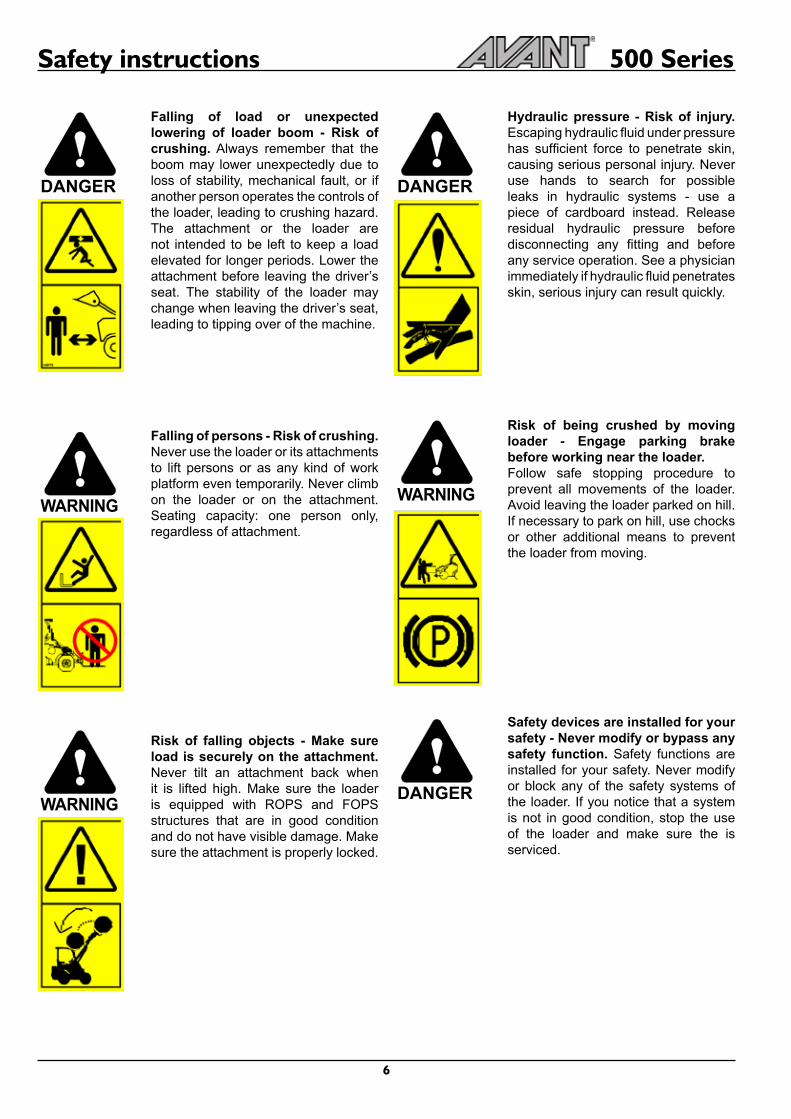
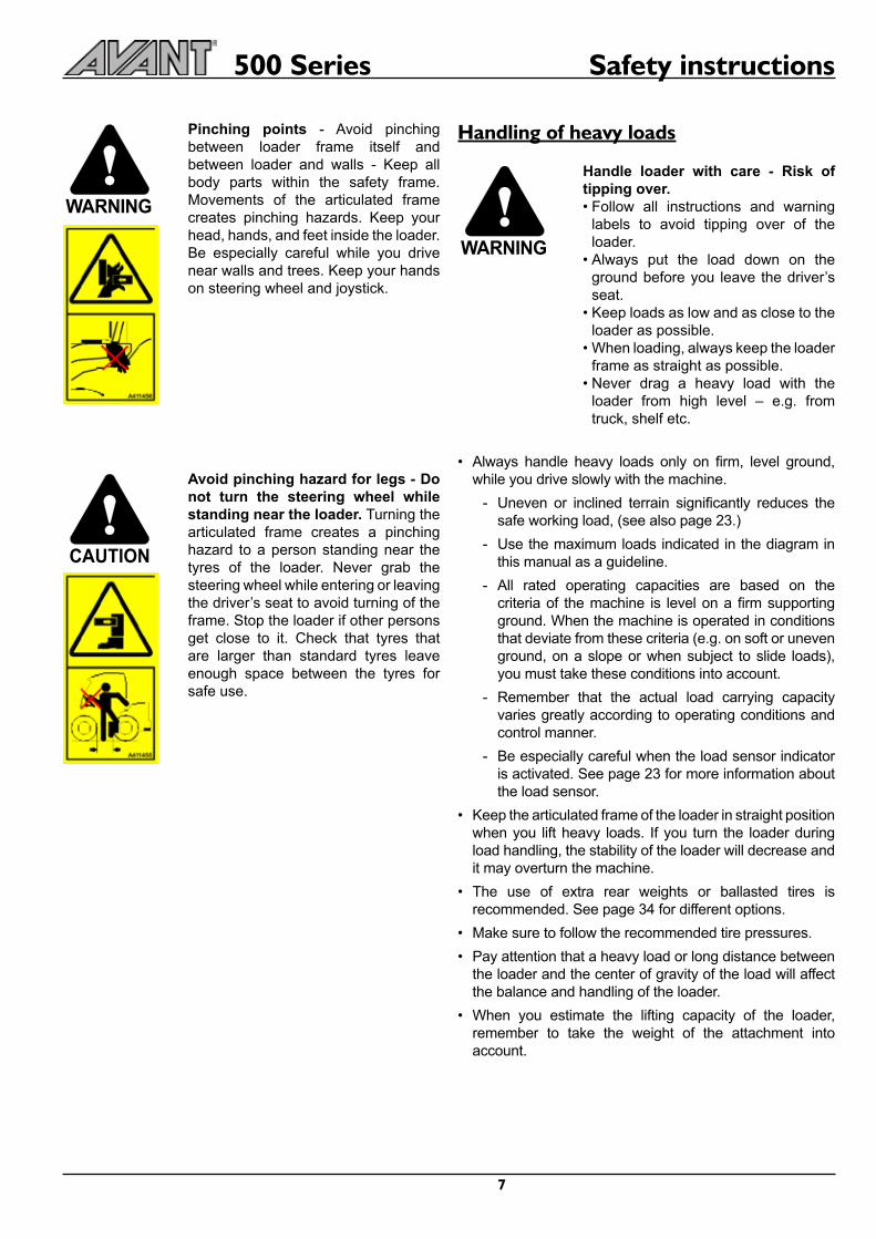


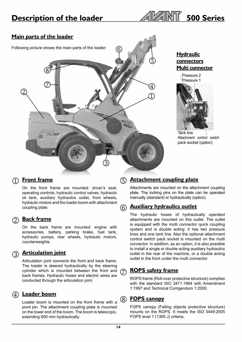


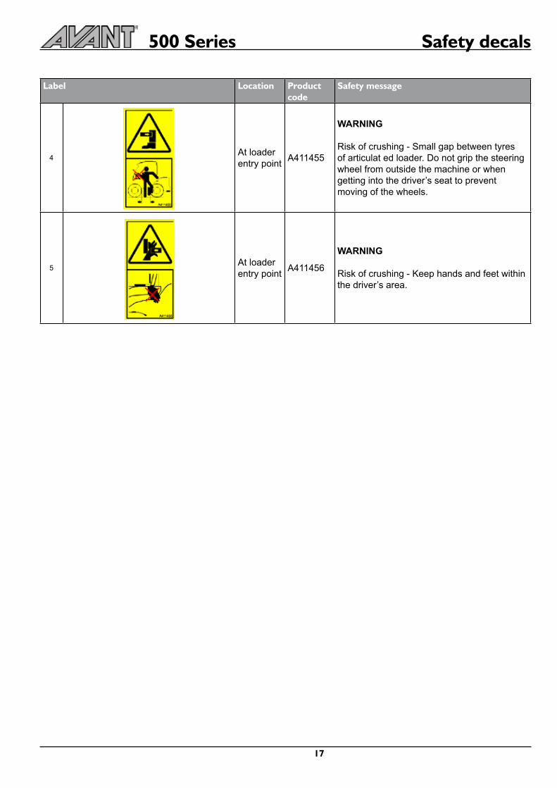


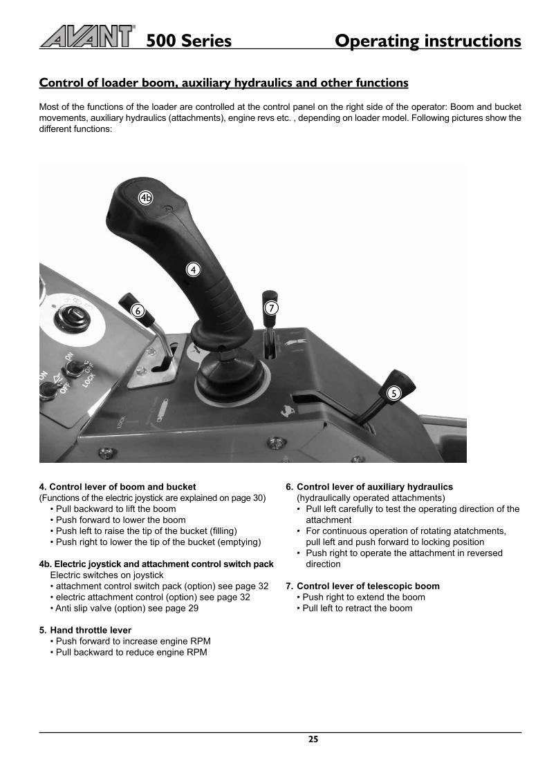


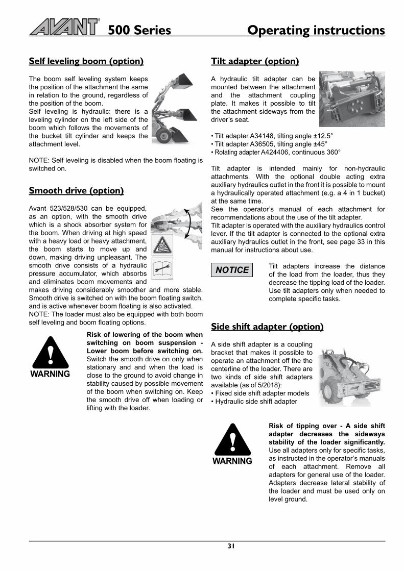


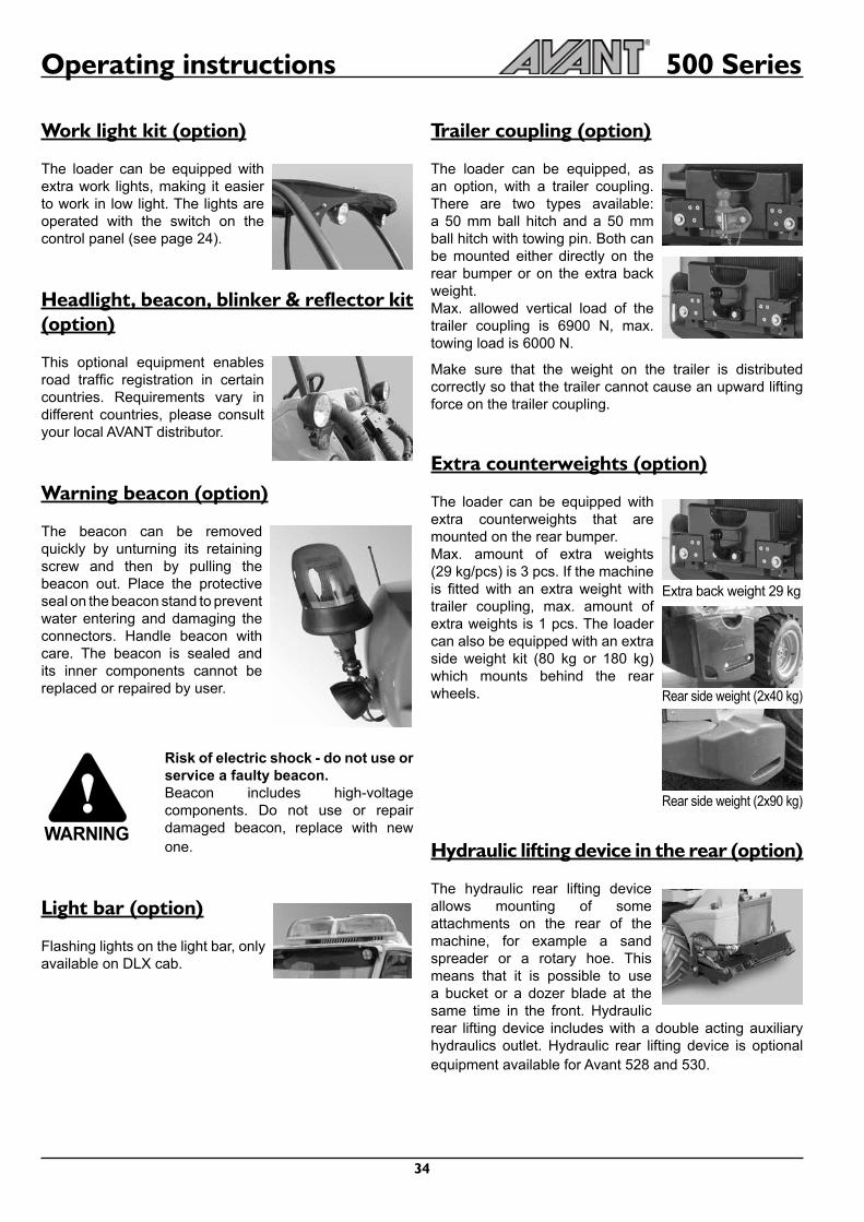


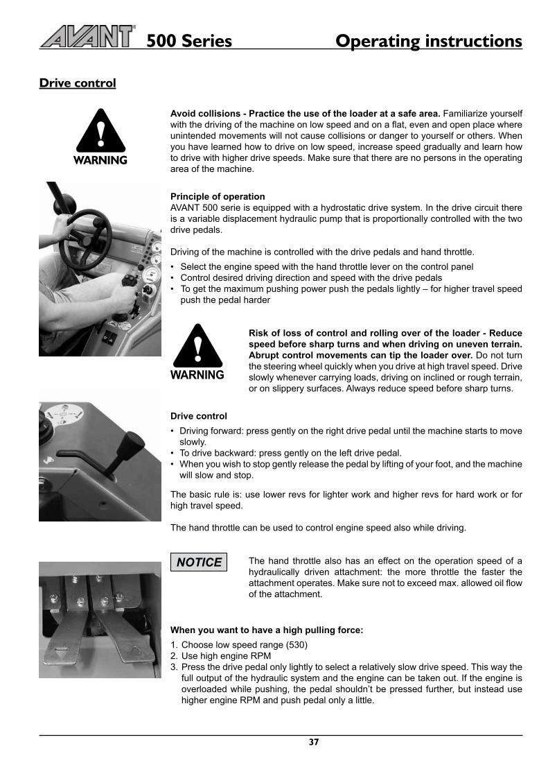
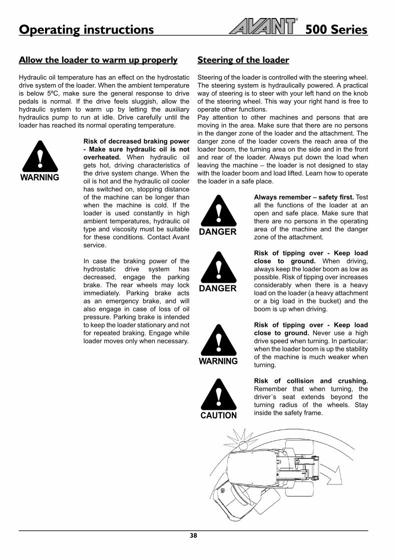

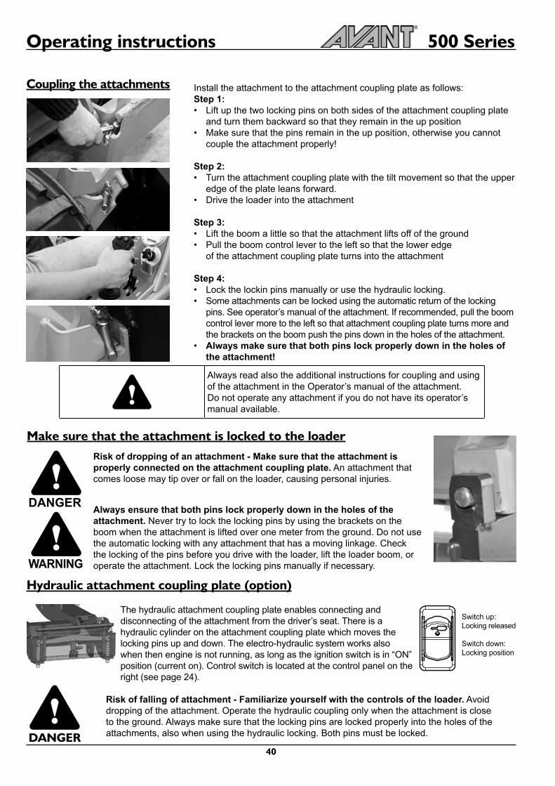


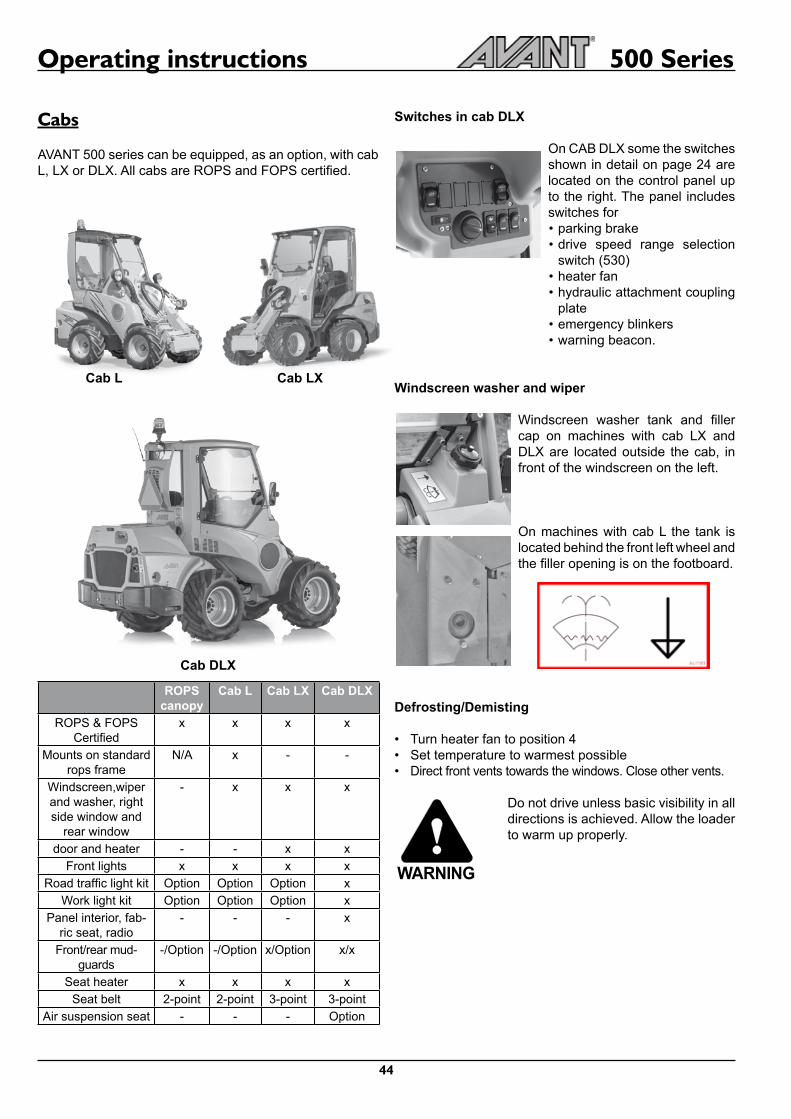

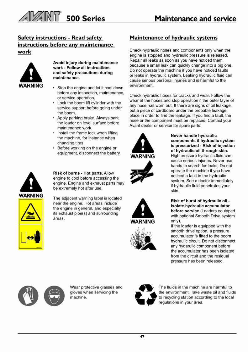


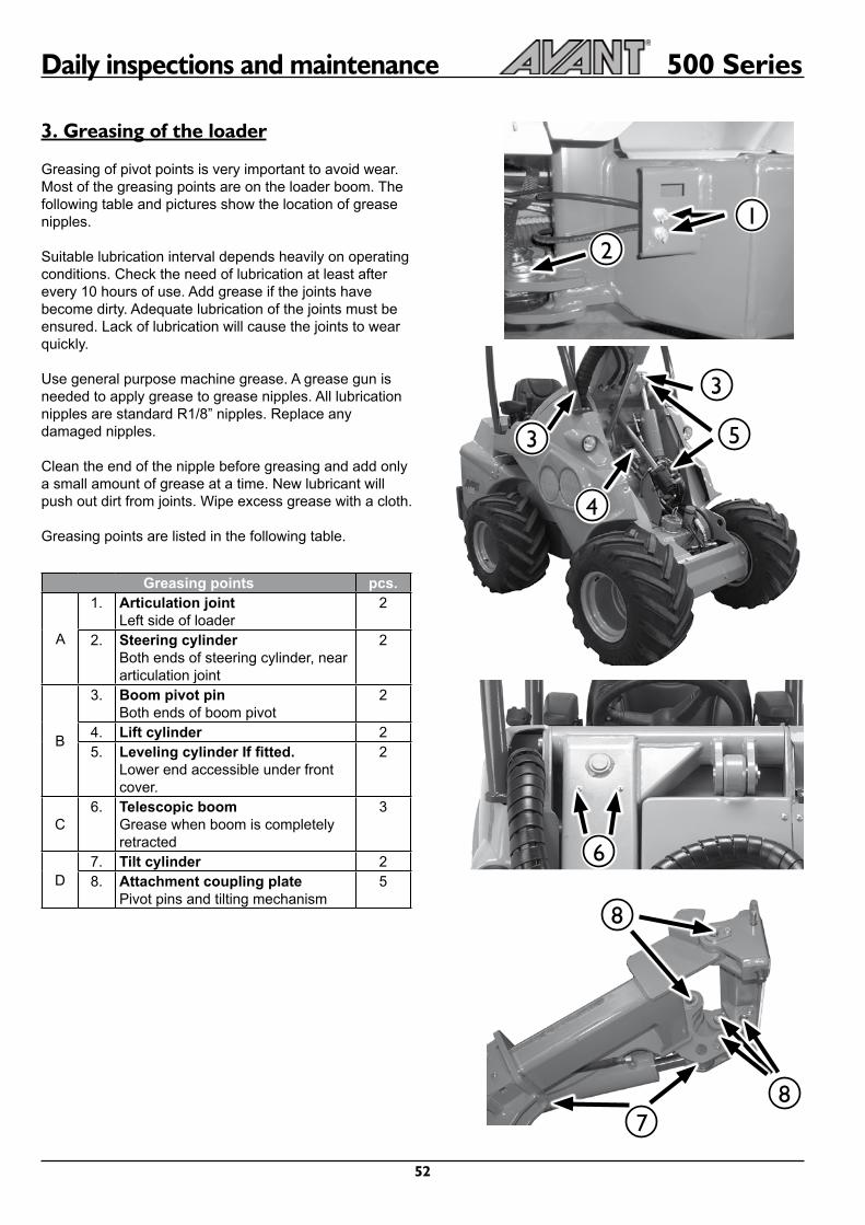


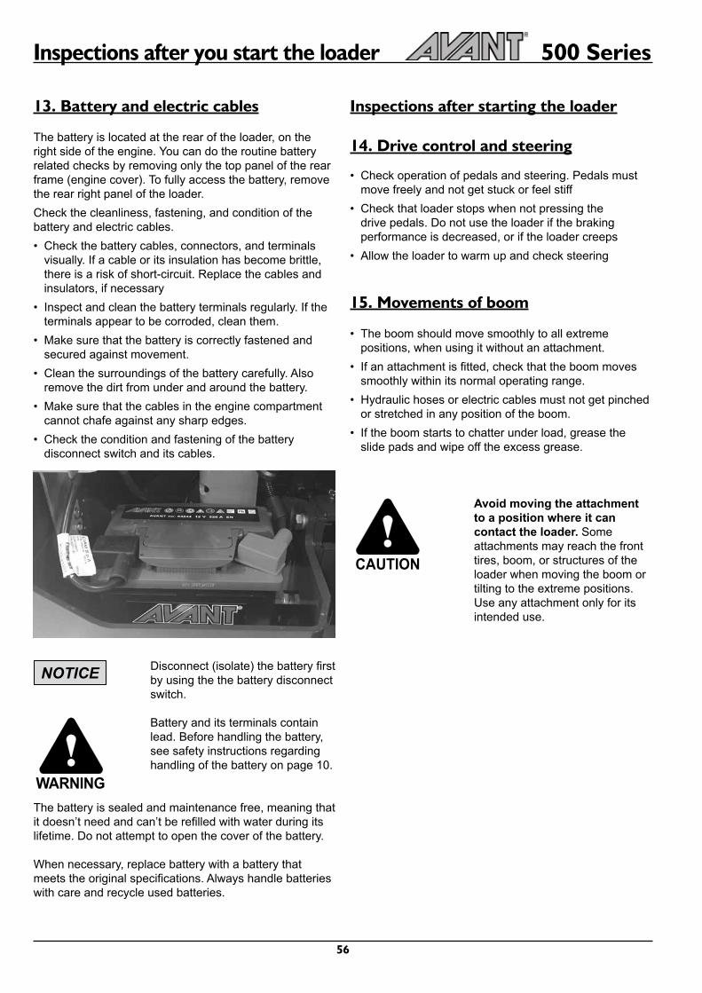
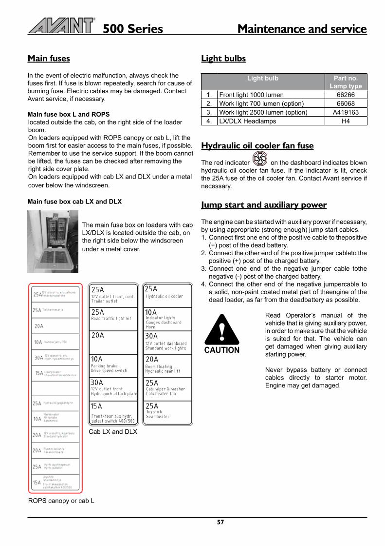

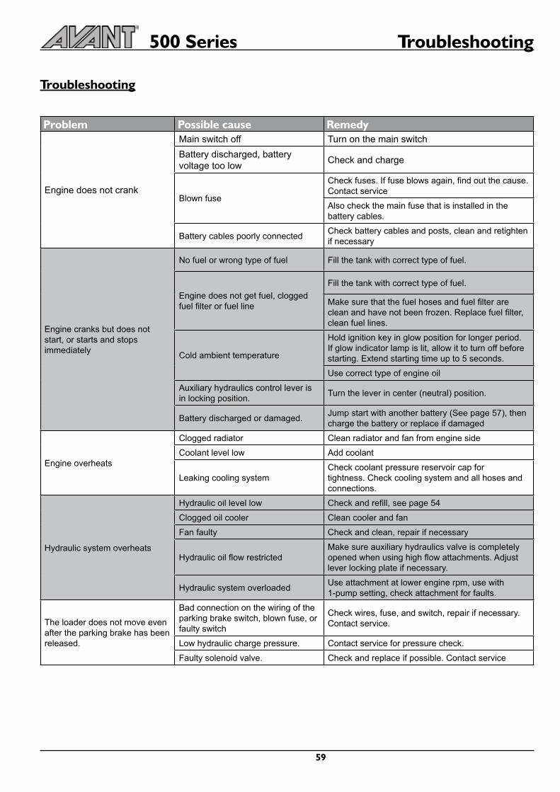


![Asymmetric Auctions - Harvard Universityscholar.harvard.edu/files/maskin/files/asymmetric_auctions.pdf · MASKIN & RILEY ASYMMETRIC AUCTIONS 415 is an interval [p3i, ai]. Heterogeneity](https://static.documents.pub/doc/80x56/5e760bf28fc02c231b5aa5dc/asymmetric-auctions-harvard-maskin-riley-asymmetric-auctions-415-is-an-interval.jpg)


