Simply Supported Beam Numerical Problems Based on Simply supported beam Q.1: Draw the SF and BM diagram for the simply supported beam loaded as shown in figure. Solution: Let reaction at support A and B be, RA and RB First find the support reaction For that, ΣV= 0 RA + RB – 2 – 4 - 2 = 0, RA + RB = 8 ...(1) Taking moment about point A, ΣMA = 0 2 x 1 + 4 x 2 + 2 x 3 – RB x 4 = 0 RB = 4KN From equation (1), RA = 4KN ...(2) ...(3) Calculation for the Shear force Diagram Draw the section line, here total 4 section line, which break the load RA and 2KN (Between Point A and C), 2KN and 4KN (Between Point C and D), 4KN and 2KN (Between Point D and E) and 2KN and RB (Between Point E and B) Consider left portion of the beam Consider section 1-1 Force on left of section 1-1 is RA SF1–1 = 4KN (constant value) Constant value means value of shear force at both nearest point of the section is equal i.e. SFA = SFC = 4KN ...(4) Consider section 2-2 Forces on left of section 2-22 is RA & 2KN SF2–2 = 4 – 2 = 2KN (constant value) Constant value means value of shear force at both nearest point of the section is equal i.e. SFC = SFD = 2KN Consider section 3-3 Forces on left of section 3-33 is RA, 2KN, 4KN SF3–3 = 4 – 2 – 4 = –2KN (constant value) ...(5)
Transcript
Simply Supported Beam
Numerical Problems Based on Simply supported beam
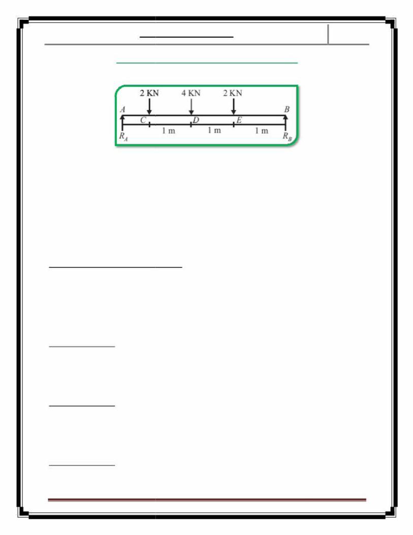
Q.1: Draw the SF and BM diagram for the simply supported beam loaded as shown in figure.
Solution:Let reaction at support A and B be, RA and RB First find the support reactionFor that,
ΣV= 0RA + RB – 2 – 4 - 2 = 0, RA + RB = 8 ...(1)
Taking moment about point A,ΣMA = 0
2 x 1 + 4 x 2 + 2 x 3 – RB x 4 = 0RB = 4KN
From equation (1),RA = 4KN
...(2)
...(3)Calculation for the Shear force DiagramDraw the section line, here total 4 section line, which break the load RA and 2KN (BetweenPoint A and C),2KN and 4KN (Between Point C and D),4KN and 2KN (Between Point D and E) and2KN and RB (Between Point E and B)Consider left portion of the beam
Consider section 1-1Force on left of section 1-1 is RA
SF1–1 = 4KN (constant value)Constant value means value of shear force at both nearest point of the section is equal i.e.
SFA = SFC = 4KN ...(4)
Consider section 2-2Forces on left of section 2-22 is RA & 2KN
SF2–2 = 4 – 2 = 2KN (constant value)Constant value means value of shear force at both nearest point of the section is equal i.e.
SFC = SFD = 2KN
Consider section 3-3Forces on left of section 3-33 is RA, 2KN, 4KN
SF3–3 = 4 – 2 – 4 = –2KN (constant value)
...(5)
Page 1
Simply Supported Beam
Constant value means value of shear force at both nearest point of the section is equal i.e.SFD = SFE = –2KN ...(6)
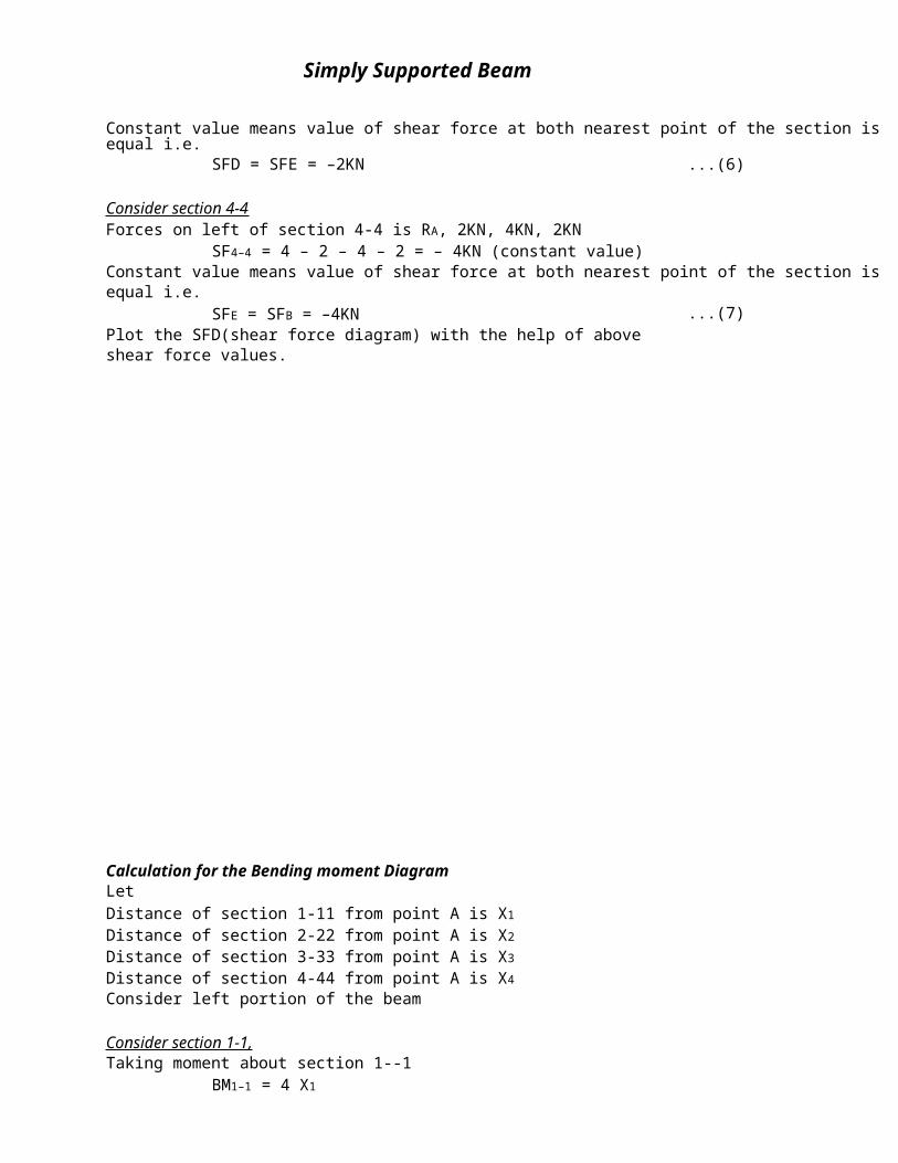
Consider section 4-4Forces on left of section 4-4 is RA, 2KN, 4KN, 2KN
SF4–4 = 4 – 2 – 4 – 2 = – 4KN (constant value)Constant value means value of shear force at both nearest point of the section is equal i.e.
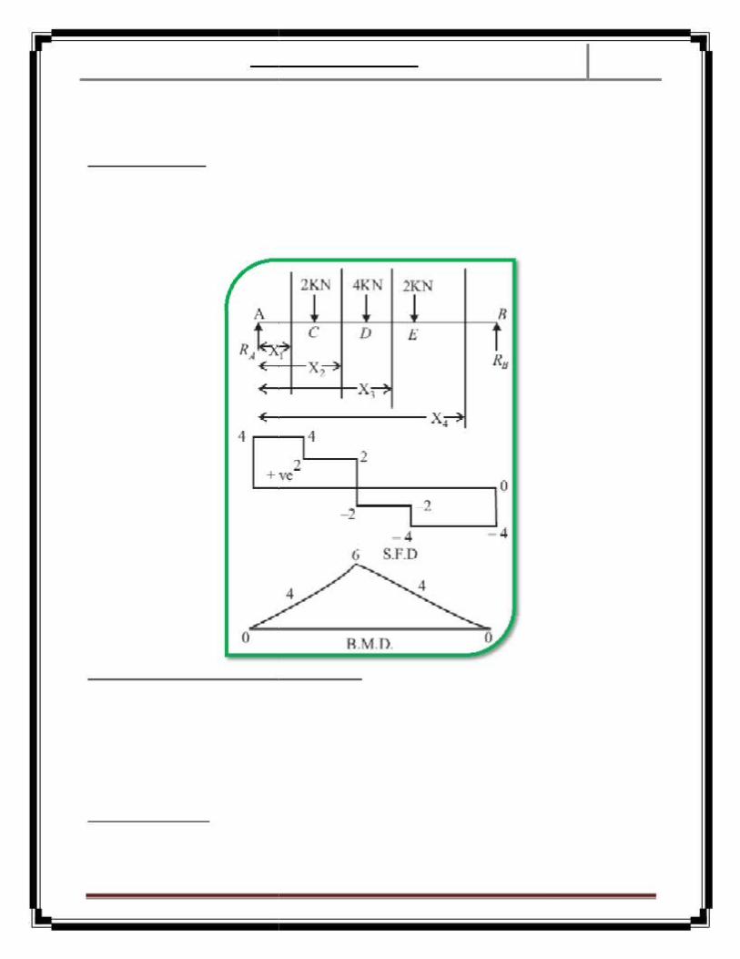
SFE = SFB = –4KNPlot the SFD(shear force diagram) with the help of above shear force values.
Calculation for the Bending moment DiagramLetDistance of section 1-11 from point A is X1
Distance of section 2-22 from point A is X2
Distance of section 3-33 from point A is X3
Distance of section 4-44 from point A is X4
Consider left portion of the beam
Consider section 1-1,Taking moment about section 1--1
BM1–1 = 4 X1
...(7)
Page 2
Simply Supported Beam
It is Equation of straight line (Y = mX + C), inclined linear.Inclined linear means value of bending moment at both nearest point of the section is varieswith
Consider section 2-2,Taking moment about section 2-2
BM2–2 = 4.X2 – 2.(X2 – 1)= 2.X2 + 2
It is Equation of straight line (Y = mX + C), inclined linear.Inclined linear means value of Bending moment at both nearest point of the section is varieswith
It is Equation of straight line (Y = mX + C), inclined linear.Inclined linear means value of Bending moment at both nearest point of the section is varieswith
It is Equation of straight line (Y = mX + C), inclined linear.Inclined linear means value of Bending moment at both nearest point of the section is varieswith
i.e. inclined line 4 to 0Plot the BMD(bending moment diag) with the help of above bending moment values.As can be seen in the second diagram of this question._____________________________________________________________________________________________________________________________________________________________________________________________________________________________________________________________________________________________________________________________________________________________________________________________________________________________________________________________________________________________________________________________________________________________________________________________________________________________________________________________________________________________________________________________________________________________________________________________________________________________________________________________________________________________________________________________________________________________________________________________________________________________________________________________________________________________________________________________________________________________________________________________________________________________________________________________________________________________________________________________________________________________________________________________________________________________________________________________________________________________________________________________________________________________________________________________________________________________________________________________________________________________________________________________________________________________________________________________________________________________________________________________________________________________________________________________________________________________________________________________________________________________________________________________________________________________________________________________________________________________________________________________________________________________________________________________________________________________________________________________________________________________________________________________________________________________________________________________________________________________________________________________________________________________________________________________________________________________________________________________________________________________________________________________________________________________________________________________________________________________________________________________________________________________________________________________________________________________________________________________________
Page 4
Simply Supported Beam
Q.2:: Draw the SF and BM diagram for the simply supported beam loaded as shown inFollowing diagram (this diagram also includes the solution also so before solving thenumerical try not to see the SFD & BMD).
Solution:Let reaction at support A and B be, RA and RB
First find the support reaction.For finding the support reaction, convert UDL in to pointload and equal to 2 X 2 = 4KN, acting at mid point of UDL i.e.3m from point A.For that,
∑V = 0RA + RB – 1 – 4 – 1 = 0,RA + RB = 6
Taking moment about point A,∑MA = 0
1 X 1 + 4 X 3 + 1 X 5 – RB X 6 = 0RB = 3KN
From equation (1),RA = 3KN
...(1)
...(2)
...(3)
Calculation for the Shear force Diagra m
Draw the section line, here total 5-section line, which breakthe load RA and 1KN (Between Point A and C),
1KN and starting of UDL (Between Point C and D), end pointof UDL and 1KN (Between Point E and F) and
1KN and RB (Between Point F and B)
LetDistance of section 1-11 from point A is X1
Distance of section 2-22 from point A is X2
Distance of section 3-33 from point A is X3
Distance of section 4-44 from point A is X4
Distance of section 5-55 from point A is X5
Consider left portion of the beamConsider section 1-1Force on left of section 1-1 is RA
SF1–1 = 3KN (constant value)Constant value means value of shear force at both nearest point of the section is equal i.e.
SFA = SFC = 3KN ...(4)Consider section 2-2
Forces on left of section 2-2 is RA & 1KNSF2–2 = 3 – 1 = 2KN (constant value)
Constant value means value of shear force at both nearest point of the section is equal i.e.SFC = SFD = 2KN
Consider section 3-3
Forces on left of section 3-3 is RA,1KN and UDL (from point D to the section line i.e. UDL on total distance of (X 3 - 2)
...(5)
Page 5
Simply Supported Beam
SF3–3 = 3 - 1 - 2(X3 - 2) = 6 - 2X3 KN (Equation of straight line)It is Equation of straight line (Y = mX + C), inclined linear.Inclined linear means value of S.F. at both nearest point of the section is varies with X3 = 2 to
i.e. inclined line 2 to -2Since here shear force changes the sign so at any point shear force will be zero and at that point bending momentis maximum.For finding the position of zero shear force equate the shear force equation to zero, i.e.
6 – 2X3 = 0; X3 = 3m,i.e. at 3m from point A bending moment is maximum.
Consider section 4-4Forces on left of section 4-4 is RA, 1KN, 4KN
SF4–4 = 3 – 1 – 4 = – 2KN (constant value)Constant value means value of shear force at both nearest point of the section is equal i.e.
SFE = SFF = -2KNConsider section 5-5Forces on left of section 5-5 is RA, 1KN, 4KN, 1KN
SF5-5 = 3 – 1 – 4 – 1 = –3KN (constant value)Constant value means value of shear force at both nearest point of the section is equal i.e.
SFE = SFB = –3KN
...(8)
...(9)Plot the SFD with the help of above shear force values.
Calculation for the Bending moment DiagramConsider left portion of the beamConsider section 1-1,Taking moment about section 1-1
BM1–1 = 3.X1It is Equation of straight line (Y = mX + C), inclined linear.Inclined linear means value of bending moment at both nearest point of the section is varies with
X1 = 0 to X1 = 1At X1 = 0
BMA = 0 ...(10)At X1 = 1
BMC = 3 ...(11)i.e. inclined line 0 to 3
Consider section 2-2,Taking moment about section 2-2
BM2-2 = 3.X2 – 1.(X2 – 1)= 2.X2 + 1
It is Equation of straight line (Y = mX + C), inclined linear.Inclined linear means value of bending moment at both nearest point of the section is varies with
X2 = 1 to X2 = 2At X2 = 1
BMC = 3 ...(12)At X2 = 2
BMD = 5 ...(13)i.e. inclined line 3 to 5
Page 6
Simply Supported Beam
Consider section 3-3,Taking moment about section 3-3
It is Equation of Parabola (Y = mX2 + C),Parabola means a parabolic curve is formed, value of bending moment at both nearest point of the section isvaries with X3 = 2 to X3 = 4
At X3 = 2BMD = 5
At X3 = 4BME = 5
But B.M. is maximum at X3 = 3, which lies between X3 = 2 to X3 = 4So we also find the value of BM at X3 = 3
At X3 = 3BMmax = 6
...(14)
...(15)
...(16)i.e. curve makes with in 5 to 6 to 5 region.Consider section 4-4, taking moment about section 4-4
It is Equation of straight line (Y = mX + C), inclined linear.Inclined linear means value of bending moment at both nearest point of the section is varies with X4 = 4 to X4 = 5
At X4 = 4BME = 5
At X4 = 5BMF = 3
...(17)
...(18)i.e. inclined line 5 to 3
Consider section 5-5,Taking moment about section 5-5
It is Equation of straight line (Y = mX + C), inclined linear.Inclined linear means value of bending moment at both nearest point of the section is varies with X5 = 5 to X5 = 6
At X5 = 5BME = 3
At X4 = 6BMF = 0
...(19)
...(20)i.e. inclined line 3 to 0
Plot the BMD with the help of above bending moment values.
Q.3: Draw the SF and BM diagram for the simply supported beam loaded as shown in figure.
Page 7
Simply Supported Beam
Solution:Let reaction at support A and B be, RA and RB Firstfind the support reaction.
For finding the support reaction, convert UDL in topoint load and equal to 20 X 1.5 = 30KN, acting atmid point of UDL i.e. 0.75m from point A.
For that,∑V = 0
RA + RB - 30 - 20 = 0, RA + RB = 50 ...(1)Taking moment about point A,
Draw the section line, here total 4-section line,which break the load RA and UDL (Between Point A and E),30KN/m and 20KN (Between Point E and D),30KN/M and 20KN (Between Point D and C) and20KN and RB (Between Point C and B)
LetDistance of section 1-11 from point A is X1
Distance of section 2-22 from point A is X2
Distance of section 3-33 from point A is X3
Distance of section 4-44 from point A is X4
Consider left portion of the beam
Consider section 1-1Force on left of section 1-1 is RA and UDL (from point A to the section line i.e. UDL on total distance of X1
SF1–1 = 21.875 -20X1 KN (Equation of straight line)It is Equation of straight line (Y = mX + C), inclined linear.
Inclined linear means value of shear force at both nearest point of the section is varies with X1 = 0 to X1 = 1.5At X1 = 0
SFA = 21.875At X1 = 1.5
SFE = –8.125
...(4)
...(5)i.e. inclined line 21.875 to – 8.125
Since here shear force changes the sign so at any point shear force will be zero and at that point bending momentis maximum.For finding the position of zero shear force equate the shear force equation to zero, i.e.21.875 -20X1 = 0; X1 = 1.09375m, i.e. at 1.09375m from point A bending moment is maximum.
Consider section 2-2Forces on left of section 2-22 is RA & 30KN
Page 8
Simply Supported Beam
SF2-2 = 21.875 – 30 = – 8.125KN (constant value)Constant value means value of shear force at both nearest point of the section is equal i.e.
SFE = SFD = – 8.125KN ...(6)
Consider section 3-3Forces on left of section 3-3 is RA & 30KN, since forces are equal that of section 2-2, so the value of shear force atsection 3-3 will be equal that of section 2-2
SF3-3 = 21.875 – 30 = – 8.125KN (constant value)Constant value means value of shear force at both nearest point of the section is equal i.e.
SFD = SFC = – 8.125KN ...(7)
Consider section 4-4Forces on left of section 4-4 is RA, 30KN, 20KN
SF4-4 = 21.875 – 30 -20 = -28.125KN (constant value)Constant value means value of shear force at both nearest point of the section is equal i.e.
SFC = SFB = –28.125KN ...(8)Plot the SFD with the help of above shear force values.
Calculation for the Bending moment DiagramConsider left portion of the beam
Consider section 1-1,Taking moment about section 1-1
BM1-1 = 21.875X1 -20X1(X1/2)
It is Equation of Parabola (Y = mX2 + C),Parabola means a parabolic curve is formed, value of bending moment at both nearest point of the section isvaries with X1 = 0 to X1 = 1.5
At X1 = 0BMA = 0 ...(9)
At X1 = 1.5BMC = 10.3125 ...(10)
But B.M. is maximum at X1 = 1.09, which lies between X1 = 0 to X1 = 1.5So we also find the value of BM at X1 = 1.09
At X1 = 1.09BMmax = 11.8 ...(11)
i.e. curve makes with in 0 to 11.8 to 10.3125 region.
Consider section 2-2,Taking moment about section 2-2
It is Equation of straight line (Y = mX + C), inclined linear.Inclined linear means value of bending moment at both nearest point of the section is varies with
X2 = 1.5 to X2 = 2At X2 = 1.5
BME = 10.3125At X2 = 2
BMD = 6.25i.e. inclined line 10.3125 to 6.25
Consider section 3-3,Taking moment about section 3-3
It is Equation of straight line (Y = mX + C), inclined linear.Inclined linear means value of bending moment at both nearest point of the section is varies with
X3 = 2 to X3 = 3At X3 = 2
BMD = 36.25At X3 = 3
BMC = 28.125
Consider section 4-4,Taking moment about section 4-4
It is Equation of straight line (Y = mX + C), inclined linear.Inclined linear means value of bending moment at both nearest point of the section is varies with
X4 = 3 to X4 = 4At X4 = 3
BMC = 28.125At X4 = 4
BMB = 0
...(14)
...(15)
...(16)
...(17)i.e. inclined line 28.125 to 0
Plot the BMD with the help of above bending moment values.
Q.4: Determine the SF and BM diagrams for the simply supported beam shown in figure No. 4. Also find themaximum bending moment.
Solution:
Since hinged at point A and D, suppose reaction at support A and D be, RAH, RAV and RDH, RDV first find the supportreaction.For finding the support reaction, convert UDL and UVL in to point load and,
Point load of UDL equal to10 X 2 = 20KN,Acting at mid point of UDL
i.e. 1m from point A.Point load of UVL equal to1/2 X 20 X 2 = 20KN, acting at a distance 1/3 of total distance i.e. 1/3m from point D.
For that,∑V = 0RAV + RDV – 20 – 20 = 0, RA + RB = 40
Taking moment about point A,∑MA = 020 X 1 + 20 X 5.33 – RDV X 6 = 0RDV = 21.1 KNFrom equation (1), RAV = 18.9KN
...(1)
...(2)
...(3)Calculation for the Shear force Diagram
Draw the section line, here total 3-section line, which break the load RAV and UDL (Between Point A and B),
Page 10
Simply Supported Beam
No load (Between Point B and C) and UVL (Between Point C and D).LetDistance of section 1-11 from point A is X1
Distance of section 2-22 from point A is X2
Distance of section 3-33 from point A is X3
Consider left portion of the beam
Consider section 1-1Force on left of section 1-1 is RAV and UDL(from point A to the section line i.e. UDL ontotal distance of X1
SF1-1 = 18.9 -10X1 KN(Equation of straight line)
It is Equation of straight line (Y = mX + C),inclined linear.Inclined linear means value of shear force atboth nearest point of the section is varieswith X1 = 0 to X1 = 2At X = 0
SFA = 18.9At X1 = 2
SFB = –1.1
...(4)
...(5)i.e. inclined line 18.9 to - 1.1
Since here shear force changes the sign so atany point shear force will be zero and at thatpoint bending moment is maximum.
For finding the position of zero shear forceequate the shear force equation to zero, i.e.
18.9 –10X1 = 0; X1 = 1.89m,i.e. at 1.89m from point A bending moment is maximum.
Consider section 2-2Forces on left of section 2-2 is RAV & 20KN
SF2-2 = 18.9 – 20 = – 1.1KN (constant value)Constant value means value of shear force at both nearest point of the section is equal i.e.
SFB = SFC = – 1.1KN
Consider section 3-3Forces on left of section 3-3 is RAV & 20KN and UVL of 20KN/m over (X3 – 4) m length,First calculate the total load of UVL over length of (X3 – 4)Consider triangle CDE and CGF
DE/GF = CD/CGSince DE = 20
20/GF = 2/(X3 – 4)GF = 10(X3 – 4)
Now load of triangleCGF = 1/2 X CG X GF = 1/2 X (X3 – 4) X 10(X3 – 4)
Parabola means a parabolic curve is formed, value of bendingmoment at both nearest point of the section is varies with X3 = 4to X3 = 6
At X3 = 4SFC = –1.1KNSFD = –21.1KN
...(8)
...(9)
Plot the SFD(shear force diagram) with the help ofabove shear force values.
Calculation for the Bending moment DiagramConsider left portion of the beam
Consider section 1-1,Taking moment about section 1-1
BM1–1 = 18.9X1 –10X1.X1/22
It is Equation of Parabola (Y = mX2 + C),Parabola means a parabolic curve is formed, value of bending moment at both nearest point of the section isvaries with X1 = 0 to X1 = 2
At X1 = 0BMA = 0
At X1 = 2BMB = 17.8
But B.M. is maximum at X 1 = 1.89 , which lies between X1 = 0 to X1 = 2So we also find the value of BM at X1 = 1.89At X1 = 1.89
BMmax = 17.86
...(10)
...(11)
...(12)i.e. curve makes with in 0 to 17.86 to 17.8 region.
Consider section 2-2,Taking moment about section 2-2
BM2-2 = 18.9X2 – 20(X2 – 1)It is Equation of straight line (Y = mX + C), inclined linear.Inclined linear means value of bending moment at both nearest point of the section is varies with X2 = 2 to X2 = 4
At X2 = 2BMB = 17.8
At X2 = 4BMC = 15.76
i.e. inclined line 17.8 to 15.76
Consider section 3-3,Taking moment about section 3-3
2
It is cubic Equation which varies with X3 = 4 to X3 = 6At X3 = 4
BMC = 15.76 ...(15)
...(13)
...(14)
Page 12
Simply Supported Beam
At X3 = 6BMD = 0 ...(16)
Plot the BMD with the help of above bending moment values.
Q.5: Draw the SF and BM diagrams for a simply supported beam 5m long carrying a load of 200N through abracket welded to the beam loaded as shown in following figure.
Solution:
The diagram is of force couple system, let us apply at C two equal and opposite forces each equal and parallel to2000N. Now the vertically upward load of 2000N at C and vertically downward load of 2000N at D forms ananticlockwise couple at C whose moment is 2000 X 0.5 = 1000NmAnd we are left with a vertically downward load of 2000N acting at C.
Let reaction at support A and B be, RA and RB first find the support reaction.
Taking moment about point A;2000 X 3 – 1000 – RB X 5 = 0
RB = 1000NRV = 0, RA + RB – 2000 = 0
RA = 1000N
Calculation for the Shear force Diagra mDraw the section line, here total 2 section line, which break the load
RA and 2000N (Between Point A and C),2000N and RB (Between Point C and B).
LetDistance of section 1-11 from point A is X1
Distance of section 2-22 from point A is X2
Consider left portion of the beam
Consider section 1-1Force on left of section 1-1 is RA
SF1-1 = 1000N (constant value)Constant value means value of shear force at both nearest point of the section is equal i.e.
SFA = SFC = 1000N
...(1)
...(2)
...(3)
Page 13
Simply Supported Beam
Consider section 2-2Forces on left of section 2-2 is RA &2000N
SF2-2 = 1000 – 2000 = –1000(constant value)Constant value means value of shearforce at both nearest point of thesection is equal i.e.SFC = SFB = –1000N ...(4)Plot the SFD with the help of aboveshear force values.
Calculation for the bending momentDiagramConsider section 1-1,Taking moment about section 1-1
BM1-1 = 1000.X1
It is Equation of straight line(Y = mX + C), inclined linear.Inclined linear means value ofbending moment at both nearestpoint of the section is varies with X1
= 0 to X1 = 3At X1 = 0
BMA = 0 ...(5)At X1 = 3
BMC = 3000 ...(6)i.e. inclined line 0 to 3000
Consider section 2-2,Taking moment about section 2-2
It is Equation of straight line (Y = mX + C), inclined linear.Inclined linear means value of Bending moment at both nearest point of the section is varies with X2 = 3 to X2 = 5
At X2 = 3BMC = 2000
At X2 = 5BMB = 0
...(7)
...(8)i.e. inclined line 2000 to 0
Plot the BMD with the help of above bending moment values. The SFD and BMD is shown in figure No.5
Q.6: A simply supported beam 6m long is subjected to a triangular load of 6000N as shown in figure below. Drawthe S.F. and B.M. diagrams for the beam.Solution:LetSuppose reaction at support A and B be, RA and RB first find the support reaction.Due to symmetry,RA = RB = 6000/2 = 3000N
Draw the section line, here total 2-section line,which break the point A,D and Point D,BLetDistance of section 1-11 from point A is X1
Distance of section 2-22 from point A is X2
Consider left portion of the beamConsider section 1-1Forces on left of section 1-1 is RA and UVL of6000N/m over X1 m length,Since, Total load = 6000 = 1/2 X AB X CD1/2 X 6 X CD = 6000, CD = 2000N ...(2)First calculate the total load of UVL over length ofX1
Consider triangle ADC and AFEDC/EF = AD/AF
Since DC = 20002000/EF = 3/X1
EF = (2000X1)/3Now load of triangle AEF = 1/2 X EF × AF
= (1/2 X 2000X1)/3 × (X1)=(1000.X12)/3 a
distance of X1/3 from F
...(3)SF1-1 = 3000 – (1000X12)/3 (Parabola)
Parabola means a parabolic curve is formed, value of bending moment at both nearest point of the section isvaries with X1 = 0 to X1 = 3
At X1 = 0SFA = 3000N
At X1 = 3SFD = 0
Consider section 2-2Forces on left of section 2-2 is RA and UVL of 2000N/m(At CD) and UVL over (X2 – 3) m length,First calculate the total load of UVL over length of (X2 – 3)Consider triangle CDB and BGH
DC/GH = DB/BGSince DC = 2000
2
2
Now load of triangle BGH = 1/2 X GH X BG2 2
2
...(4)
...(5)
...(6)Load of CDB = 1/2 X 3 X 2000 = 3000Now load of CDGH = load of CDB - load of BGH
= 3000 – 1000(6 – X2)2/3 ...(7)2
Parabola means a parabolic curve is formed, value of bending moment at both nearest point of the section isvaries with X2 = 3 to X2 = 6
At X2 = 3SFA = 0
At X2 = 6...(8)
Page 15
BM1-1 = 3000X1 – [(1000X1 )/3] X1/3
Simply Supported Beam
SFD = –3000N ...(9)Plot the SFD with the help of above value asshown in fig.Since SF change its sign at X2 = 3, that means at adistance of 3m from point A bending moment ismaximum.
Calculation for the Bending moment DiagramConsider section 1-1
2
(Cubic)Cubic means a parabolic curve is formed, value ofbending moment at both nearest point of thesection is varies with X1 = 0 to X1 = 3
At X1 = 0BMA = 0 ...(10)
At X1 = 3BMD = 6000 ...(11)
Consider section 2-2Point of CG of any trapezium is = h/3[(b + 2a)/(a +b)]i.e. Distance of C.G of the trapezium CDGH isgiven by,
BM2-2 = 3000X2-3000(X2-2)-[3000-1000(6 – X2)2/3]{+ (X2 – 3)(12 – X2)}/{3(9 – X2)} (Equation of Parabola)Parabola means a parabolic curve is formed, value of bending moment at both nearest point of the section isvaries with X2 = 3 to X2 = 6
Q.7:: A simply supported beam carries distributed load varying uniformly from 125N/m at one end to 250N/m atthe other. Draw the SF and BM diagram and determine the maximum B.M.Solution:Total load = Area of the load diagram ABEC= Rectangle ABED + Triangle DEC= (AB X BE) + (1/2 X DE X DC) = (9 X 125) +
[1/2 X 9 X (250-125)]
Page 16
Simply Supported Beam
= 1125N + 562.5N ...(1)Centroid of the load of 1125N (rectangular load) is at a distance of 9/2 = 4.5m from AD and the centroid of the loadof 562.5N (Triangular load) is at a distance of 1/3 X DE = 1/3 X 9 = 3m from point A.Let support reaction at A and B be RA and RB. For finding the support reaction,Taking moment about point A,1125 X 4.5 + 562.5 X 3 - RB X 9 = 0
RB = 750N ...(2)Now, RV = 0
RA + RB = 1125 + 562.5 = 1687.5RA = 937.5N ...(3)
Calculation for the Shear force DiagramDraw the section line, here total 1-section line, which break the point A and BLetDistance of section 1-1 from point B is XConsider right portion of the beamConsider section 1-1Forces on right of section 1-1 is RB and Load of PBEF and Load of EFH
SF1-1 = RB - load on the area PBEF - load on the area EFH= RB - X.125 - 1/2.X.FH
In the equiangular triangles DEC and FEHDC/DE = FH/FE
or,125/9 = FH/XFH = 125X/9
S.F. between B and A = 750 - 125X - 125X2/18 (Equation of Parabola)Parabola means a parabolic curve is formed, value of bending moment at both nearest point of the section isvaries with X = 0 to X = 9
At X = 0SFB = 750N ...(4)
At X = 9SFA = –937.5N ...(5)
Since the value of SF changes its sign, which is between the point A and B we get max. BM For the point of zeroshear,
750 – 125X – 125X2/18 = 0On solving we get, X = 4.75m
That is BM is max. at X = 4.75 from point B
Calculation for the Bending moment DiagramConsider section 1-1