72
5MX-F8199-E0 AT115 OWNER’S MANUAL
| Date post: | 22-Dec-2015 |
| Category: |
Documents |
| Upload: | myravelle-vidallon-negro |
| View: | 3 times |
| Download: | 0 times |

5MX-F8199-E0
AT115PRINTED IN INDONESIA
YAMAHA MOTOR CO., LTD.
OWNER’S MANUAL

Engine start procedure
Engine oil replacement
V-belt inspection
Load limit
Before pushing start button, make sure to apply the Front or Rear Brake and that the Sidestand is retracted.
Engine oil replacement : Every 2000 km.Recommended oil : SAE20W - 50 type SF Class Motor Oil
Convenience hook : 1 kg, Helmet box: 5 kg5MX-F835Y-00
Periodic maintenance must be performed by any authorized Yamaha Dealer (Refer tothe Owner's Manual for details.)

00000 INTRODUCTION
our purchase of the Yamaha AT115. This model is the result ofence in the production of fine sporting, touring, and pacesettingepresents the high degree of craftsmanship and reliability that leader in these fields.
eration, inspection, and basicions concerning the operationamaha dealer.
EAU04229*
td.
use of
is expressly prohibited.Printed in Indonesia.
U5MXE0.book Page 1 Thursday, December 20, 2001 2:08 PM
EAU
Congratulations on yYamaha’s vast experiracing machines. It rhave made Yamaha a
This manual will givemaintenance of this mor maintenance of yo
you an understanding of the opotorcycle. If you have any quest
ur motorcycle, please consult a Y
AT115OWNER’S MANUAL
©2001 by Yamaha Motor Co., L1st edition, December 2001
All rights reserved.Any reprinting or unauthorizedwithout the written permission
Yamaha Motor Co., Ltd.

EAU00005PORTANT MANUAL INFORMATION
ticularly important information is distinguished in this manual by the following notations:
ERT! YOUR SAFETY IS
U5MXE0.book Page 1 Thursday, December 20, 2001 2:08 PM
IM
Par
re injury or death to theting or repairing the
to avoid damage to the
clearer.
torcycle and should remain
nd quality. Therefore, whilelable at the time of printing,nd this manual. If you have
aha dealer.
EW000002
Y BEFORE OPERATING
N
The Safety Alert Symbol mINVOLVED!
WARNING Failure to follow WARNINGmotorcycle operator, a bmotorcycle.
CAUTION: A CAUTION indicates specimotorcycle.
OTE: A NOTE provides key informa
NOTE:_
� This manual should be conwith it even if the motorcycl
� Yamaha continually seeks this manual contains the mthere may be minor discrepany questions concerning t
_
WARNING_
PLEASE READ THIS MANUATHIS MOTORCYCLE. _
eans ATTENTION! BECOME AL
instructions could result in seveystander, or a person inspec
al precautions that must be taken
tion to make procedures easier or
sidered a permanent part of this moe is subsequently sold.advancements in product design aost current product information avaiancies between your motorcycle a
his manual, please consult your Yam
L CAREFULLY AND COMPLETEL

ABLE OF CONTENTS
D IMPORTANT RIDING ....................................................5-1rming up a cold engine .............5-1 engine .....................................5-2
....................................................5-2d deceleration ...........................5-3
....................................................5-3 .................................................5-4
....................................................5-5
....................................................5-6
TENANCE AND MINOR ....................................................6-1t ..................................................6-1nance and lubrication chart ......6-2installing the cowling and ....................................................6-4park plug ....................................6-7oil strainer ..................................6-9ion oil .......................................6-11r filter element, V-belt case ents, and check hoses ............6-13arburetor ..................................6-16ngine idling speed ...................6-17rottle cable free play ...............6-17
alve clearance .........................6-18
U5MXE0.book Page 1 Thursday, December 20, 2001 2:08 PM
EAU
1
2
3
4
00009 T
GIVE SAFETY THE RIGHT OF WAY .................1-1
DESCRIPTION ...................................................2-1Left view.............................................................2-1Right view...........................................................2-2Controls and instruments ...................................2-3
INSTRUMENT AND CONTROL FUNCTIONS ....3-1Main switch/steering lock ..................................3-1Indicator lights ...................................................3-2Speedometer unit ..............................................3-2Fuel gauge ........................................................3-2Handlebar switches ...........................................3-3Front brake lever ...............................................3-4Rear brake lever ................................................3-4Fuel tank cap .....................................................3-4Fuel ...................................................................3-5Starter (choke) lever ..........................................3-6Kickstarter .........................................................3-6Seat ...................................................................3-6Helmet box ........................................................3-7Convenience hook .............................................3-8
PRE-OPERATION CHECKS ...............................4-1Pre-operation check list .....................................4-1
OPERATION ANPOINTS............Starting and waStarting a warmStarting off .....Acceleration anBraking ..........Engine break-inParking ..........General note ..
PERIODIC MAINREPAIR............Owner’s tool kiPeriodic mainteRemoving and
panels ........Checking the sEngine oil and Final transmissCleaning the ai
air filter elemAdjusting the cAdjusting the eAdjusting the thAdjusting the v
5
6

TA
LEANING AND STORAGE.....7-1..................................................7-1..................................................7-1
S...............................................8-1..................................................8-1
ORMATION..............................9-1mbers .......................................9-1
ber .........................................9-1mber ........................................9-1
U5MXE0.book Page 2 Thursday, December 20, 2001 2:08 PM
BLE OF CONTENTS
Tires ................................................................6-19Spoke wheels ..................................................6-21Checking the front brake lever free play ..........6-21Adjusting the rear brake lever free play ..........6-22Checking the front brake pads and rear
brake shoes .................................................6-23Checking the brake fluid level .........................6-24Changing the brake fluid .................................6-25Checking the V-belt .........................................6-25Checking and lubricating the cables ...............6-25Checking and lubricating the throttle grip
and cable .....................................................6-26Lubricating the front and rear brake levers .....6-26Checking and lubricating the centerstand
and sidestand ..............................................6-27Checking the front fork ....................................6-27Checking the steering .....................................6-28Checking the wheel bearings ..........................6-29Battery .............................................................6-29Replacing the fuse ..........................................6-31Replacing a headlight bulb ..............................6-33Replacing a front turn signal light bulb ............6-34Replacing the tail/brake light bulb or a rear
turn signal light bulb ....................................6-35Troubleshooting ..............................................6-37Troubleshooting chart .....................................6-38
MOTORCYCLE CA. CLEANING ..B. STORAGE...
SPECIFICATIONSpecifications ..
CONSUMER INFIdentification nuFrame serial numEngine serial nu
7
8
9
1
2
3
4
5
6
7
8
9
THE RIGHT OF WAY
unsurpassed feeling of power andst accept; even the best motorcycle
lue and operating condition of yourue for the rider: good performancemedication, drugs and alcohol is, ofers—must always be at their mental alcohol, there is a tendency to take
seat belts are for car drivers andr made of leather or tear-resistantloves and a properly fitting helmet.relessness. Although full-coveragety and protection, motorcyclists will risk of going too fast and are apt tohe good motorcyclist rides safely,
e caused by others.
U5MXE0.book Page 1 Thursday, December 20, 2001 2:08 PM
EAU
1-1
00021
1- GIVE SAFETY
Motorcycles are fascinating vehicles, which can give you an freedom. However, they also impose certain limits, which you mudoes not ignore the laws of physics.
Regular care and maintenance are essential for preserving vamotorcycle. Moreover, what is true for the motorcycle is also trdepends on being in good shape. Riding under the influence of course, out of the question. Motorcycle riders—more than car drivand physical best. Under the influence of even small amounts ofdangerous risks.
Protective clothing is as essential for the motorcycle rider as passengers. Always wear a complete motorcycle suit (whethesynthetic materials with protectors), sturdy boots, motorcycle gOptimum protective wear, however, should not encourage cahelmets and suits, in particular, create an illusion of total safealways be vulnerable. Riders who lack critical self-control run thetake chances. This is even more dangerous in wet weather. Tpredictably and defensively—avoiding all dangers, including thos
Enjoy your ride!
2
EAU00026
U5MXE0.book Page 1 Thursday, December 20, 2001 2:08 PM
2-DE
Le
(page 3-6)B (page 6-10)A (page 6-10)
1.2.3.
2-1
SCRIPTION
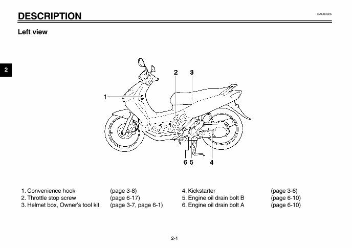
ft view
Convenience hook (page 3-8)Throttle stop screw (page 6-17)Helmet box, Owner’s tool kit (page 3-7, page 6-1)
4. Kickstarter5. Engine oil drain bolt 6. Engine oil drain bolt

DESCRIPTION
2
Ri
7.8.9.
10.
U5MXE0.book Page 2 Thursday, December 20, 2001 2:08 PM
2-2
ght view
Engine oil filler cap (page 6-9)Air filter element (page 6-13)Battery (page 6-29)Fuses (page 6-31)

D
2
C
1234
(page 3-2)(page 3-3)(page 6-17)(page 3-4)
U5MXE0.book Page 3 Thursday, December 20, 2001 2:08 PM
ESCRIPTION
2-3
ontrols and instruments
. Rear brake lever (page 3-4)
. Starter choke lever (page 3-6)
. Left handlebar switches (page 3-3)
. Speedometer unit (page 3-2)
5. Fuel gauge6. Start switch7. Throttle grip8. Front brake lever

3
NTROL FUNCTIONS
unlock the steeringsh the key in, and then turn it toFF” while still pushing it.
EW000016
WARNINGver turn the key to “OFF” orOCK” while the motorcycle isoving, otherwise the electricalstems will be switched off, whichay result in loss of control or ancident. Make sure that the motor-cle is stopped before turning they to “OFF” or “LOCK”.
Push.Turn.
U5MXE0.book Page 1 Thursday, December 20, 2001 2:08 PM
EAU
MThthuspo
OAlpoonke
OAlca
3-1
00027
3-INSTRUMENT AND CO
EAU00029
ain switch/steering lock e main switch/steering lock controls
e ignition and lighting systems, and ised to lock the steering. The varioussitions are described below.
EAU00030*
Nl electrical systems are supplied withwer, and the meter lighting comes, and the engine can be started. They cannot be removed.
EAU00038
FFl electrical systems are off. The keyn be removed.
EAU00040
LOCKThe steering is locked, and all electricalsystems are off. The key can be re-moved.
To lock the steering1. Turn the handlebars all the way to
the left.2. Push the key in from the “OFF” po-
sition, and then turn it to “LOCK”while still pushing it.
3. Remove the key.
ToPu“O
_
Ne“Lmsymaccyke_
1.2.
IN
3
Ind
TuanThes pus
HigThhigon.
EAU02950*
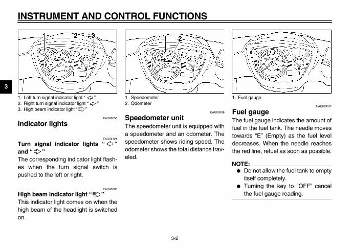
el gauge fuel gauge indicates the amount of
l in the fuel tank. The needle movesards “E” (Empty) as the fuel levelreases. When the needle reaches red line, refuel as soon as possible.
TE:Do not allow the fuel tank to emptyitself completely. Turning the key to “OFF” cancelthe fuel gauge reading.
1. L2. R3. H
uel gauge
U5MXE0.book Page 2 Thursday, December 20, 2001 2:08 PM
STRUMENT AND CONTROL FUNCTIONS
3-2
EAU00056
icator lights
EAU04121
rn signal indicator lights “ ”d “ ” e corresponding indicator light flash-
when the turn signal switch ished to the left or right.
EAU00063
h beam indicator light “ ” is indicator light comes on when theh beam of the headlight is switched
EAU00098
Speedometer unit The speedometer unit is equipped witha speedometer and an odometer. Thespeedometer shows riding speed. Theodometer shows the total distance trav-eled.
FuThefuetowdecthe
NO_
�
�
_
eft turn signal indicator light “ ”ight turn signal indicator light “ ”igh beam indicator light “ ”
1. Speedometer2. Odometer
1. F
NTROL FUNCTIONS
3
H
LiSthsw
EAU00143
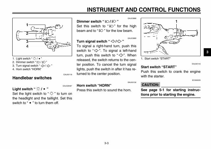
art switch “START” sh this switch to crank the engine
th the starter.EC000005
AUTION:e page 5-1 for starting instruc-ns prior to starting the engine.
1.2.3.4.
Start switch “START”
U5MXE0.book Page 3 Thursday, December 20, 2001 2:08 PM
INSTRUMENT AND CO
3-3
EAU00118
andlebar switches
EAU02948*
ght switch “ / ” et the light switch to “ ” to turn one headlight and the taillight. Set thisitch to “ ” to turn them off.
EAU03888
Dimmer switch “ / ” Set this switch to “ ” for the highbeam and to “ ” for the low beam.
EAU03889
Turn signal switch “ / ” To signal a right-hand turn, push thisswitch to “ ”. To signal a left-handturn, push this switch to “ ”. Whenreleased, the switch returns to the cen-ter position. To cancel the turn signallights, push the switch in after it has re-turned to the center position.
EAU00130
Horn switch “HORN” Press this switch to sound the horn.
StPuwi
C_
Setio_
Light switch “ / ”Dimmer switch “ / ”Turn signal switch “ / ”Horn switch “HORN”
1.
IN
3
FrThrighbrabar
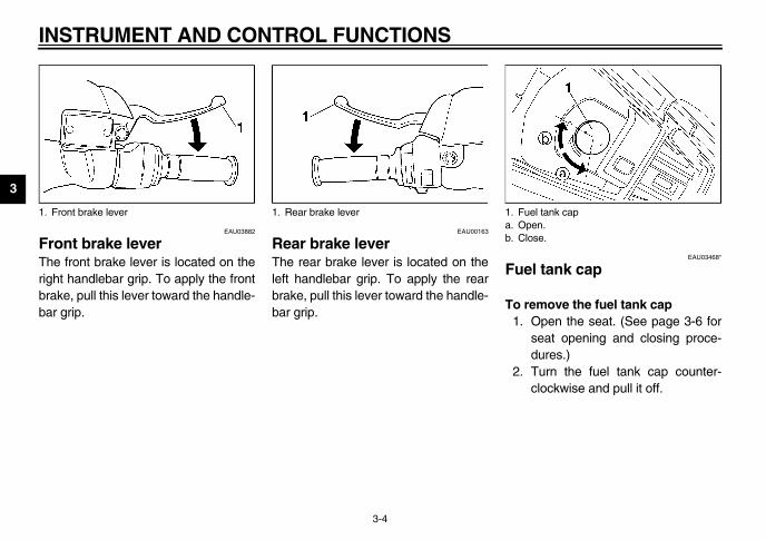
EAU03468*
el tank cap
remove the fuel tank capOpen the seat. (See page 3-6 forseat opening and closing proce-dures.)Turn the fuel tank cap counter-clockwise and pull it off.
1. F uel tank cappen.lose.
U5MXE0.book Page 4 Thursday, December 20, 2001 2:08 PM
STRUMENT AND CONTROL FUNCTIONS
3-4
EAU03882
ont brake lever e front brake lever is located on thet handlebar grip. To apply the frontke, pull this lever toward the handle- grip.
EAU00163
Rear brake lever The rear brake lever is located on theleft handlebar grip. To apply the rearbrake, pull this lever toward the handle-bar grip.
Fu
To 1.
2.
ront brake lever 1. Rear brake lever 1. Fa. Ob. C

NTROL FUNCTIONS
3
To1
2
_
Mpr_
EAU00185
AUTION:mediately wipe off spilled fuel
ith a clean, dry, soft cloth, sinceel may deteriorate painted surfac- or plastic parts.
EAU00187*
Recommended fuel:Regular gasoline
Fuel tank capacity:Total amount:
4.9 L
U5MXE0.book Page 5 Thursday, December 20, 2001 2:08 PM
INSTRUMENT AND CO
3-5
install the fuel tank cap. Insert the fuel tank cap into the
tank opening and turn it clockwiseuntil the alignment marks on thecap and tank are aligned.
. Close the seat.EW000024
WARNINGake sure that the fuel tank cap isoperly installed before riding.
EAU03753
Fuel Make sure that there is sufficient fuel inthe tank. Fill the fuel tank to the bottomof the filler tube as shown.
EW000130
WARNING_
� Do not overfill the fuel tank, oth-erwise it may overflow when thefuel warms up and expands.
� Avoid spilling fuel on the hotengine.
_
C_
Imwfues_
1. Fuel tank filler tube2. Fuel level

IN
3
StStaair-theMotheMothe
EAU03802*
at
open the seatPlace the motorcycle on the cen-terstand. Insert the key into the main switch,and then turn it counterclockwise.
TE: not push inward when turning the.
Fold the seat up.
1. S pen.
U5MXE0.book Page 6 Thursday, December 20, 2001 2:08 PM
STRUMENT AND CONTROL FUNCTIONS
3-6
EAU03839
arter (choke) lever “ ” rting a cold engine requires a richerfuel mixture, which is supplied by starter (choke).ve the lever in direction a to turn on starter (choke).ve the lever in direction b to turn off starter (choke).
EAU00214
Kickstarter To start the engine, fold out the kick-starter lever, move it down lightly withyour foot until the gears engage, andthen push it down smoothly but force-fully.
Se
To 1.
2.
NO_
Dokey_
3.
tarter (choke) lever “ ” 1. Kickstarter 1. O
NTROL FUNCTIONS
3
To1
2
N_
Mcu_
EC000010*
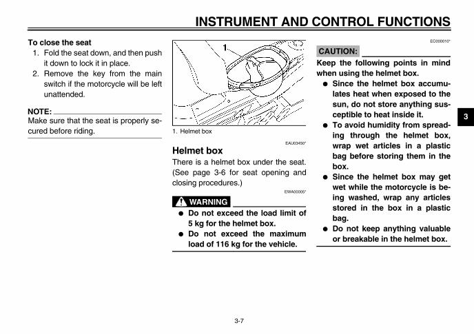
AUTION:ep the following points in mind
hen using the helmet box.� Since the helmet box accumu-
lates heat when exposed to thesun, do not store anything sus-ceptible to heat inside it.
� To avoid humidity from spread-ing through the helmet box,wrap wet articles in a plasticbag before storing them in thebox.
� Since the helmet box may getwet while the motorcycle is be-ing washed, wrap any articlesstored in the box in a plasticbag.
� Do not keep anything valuableor breakable in the helmet box.
U5MXE0.book Page 7 Thursday, December 20, 2001 2:08 PM
INSTRUMENT AND CO
3-7
close the seat. Fold the seat down, and then push
it down to lock it in place.. Remove the key from the main
switch if the motorcycle will be leftunattended.
OTE:ake sure that the seat is properly se-red before riding.
EAU03450*
Helmet box There is a helmet box under the seat.(See page 3-6 for seat opening andclosing procedures.)
EWA00005*
WARNING_
� Do not exceed the load limit of5 kg for the helmet box.
� Do not exceed the maximumload of 116 kg for the vehicle.
_
C_
Kew
_
1. Helmet box
IN
3
Toplafron
NO_
�
�
_
U5MXE0.book Page 8 Thursday, December 20, 2001 2:08 PM
STRUMENT AND CONTROL FUNCTIONS
3-8
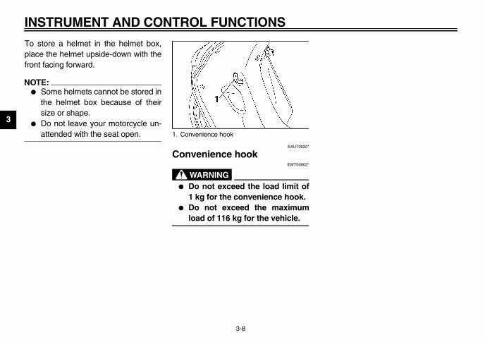
store a helmet in the helmet box,ce the helmet upside-down with thet facing forward.
TE:Some helmets cannot be stored inthe helmet box because of theirsize or shape.Do not leave your motorcycle un-attended with the seat open.
EAUT0020*
Convenience hookEWT00002*
WARNING_
� Do not exceed the load limit of1 kg for the convenience hook.
� Do not exceed the maximumload of 116 kg for the vehicle.
_
1. Convenience hook
4
PERATION CHECKS
eteriorate quickly and unexpectedly,s). Any damage, fluid leakage or loss addition to a thorough visual inspec-
EAU03439
PAGE
3-5
6-9
6-11–6-12
6-21–6-24
6-22–6-23
te cable and 6-17–6-18, 6-26
6-25
6-19–6-21
U5MXE0.book Page 1 Thursday, December 20, 2001 2:08 PM
EAU
Thevoftio
CO
F
E
F
F
R
T
C
W
4-1
01114
4-PRE-O
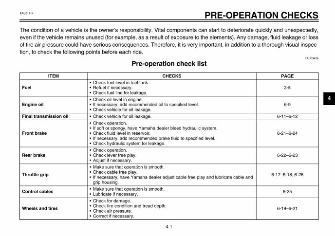
e condition of a vehicle is the owner’s responsibility. Vital components can start to den if the vehicle remains unused (for example, as a result of exposure to the element tire air pressure could have serious consequences. Therefore, it is very important, inn, to check the following points before each ride.
Pre-operation check list -01E
ITEM CHECKS
uel• Check fuel level in fuel tank.• Refuel if necessary.• Check fuel line for leakage.
ngine oil• Check oil level in engine.• If necessary, add recommended oil to specified level.• Check vehicle for oil leakage.
inal transmission oil • Check vehicle for oil leakage.
ront brake
• Check operation.• If soft or spongy, have Yamaha dealer bleed hydraulic system.• Check fluid level in reservoir.• If necessary, add recommended brake fluid to specified level.• Check hydraulic system for leakage.
ear brake• Check operation.• Check lever free play.• Adjust if necessary.
hrottle grip
• Make sure that operation is smooth.• Check cable free play.• If necessary, have Yamaha dealer adjust cable free play and lubrica
grip housing.
ontrol cables • Make sure that operation is smooth.• Lubricate if necessary.
heels and tires
• Check for damage.• Check tire condition and tread depth.• Check air pressure.• Correct if necessary.

PR
4NO_
Pre ction can be accomplished in a verysho_
EWA00033
_
If a ed and repaired before operatingthe_
Br 6-26
Ce 6-27
Ch —
Insan —
Ba 6-29–6-31
PAGE
U5MXE0.book Page 2 Thursday, December 20, 2001 2:08 PM
E-OPERATION CHECKS
4-2
TE:-operation checks should be made each time the motorcycle is used. Such an inspert time; and the added safety it assures is more than worth the time involved.
WARNINGny item in the Pre-operation check list is not working properly, have it inspect motorcycle.
ake levers • Make sure that operation is smooth.• Lubricate lever pivoting points if necessary.
nterstand, sidestand • Make sure that operation is smooth.• Lubricate pivots if necessary.
assis fasteners • Make sure that all nuts, bolts and screws are properly tightened.• Tighten if necessary.
truments, lights, signals d switches
• Check operation. • Correct if necessary.
ttery • Check fluid level.• Fill with distilled water if necessary.
ITEM CHECKS
5
NT RIDING POINTS
Start the engine by pushing thestart switch, while applying thefront or rear brake or by pushingthe kickstarter lever down.
E:e engine fails to start, release thet switch, wait a few seconds, and try again. Each starting attempt
uld be as short as possible to pre-e the battery. Do not crank the en- more than 5 seconds on any onempt. If the engine does not start the starter motor, try using thestarter with the motorcycle on theterstand.
tart switch “START”ickstarter
U5MXE0.book Page 1 Thursday, December 20, 2001 2:08 PM
EAU
_
_
5-100372
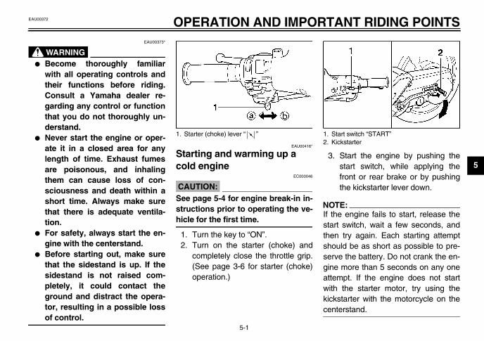
5-OPERATION AND IMPORTAEAU00373*
WARNING� Become thoroughly familiar
with all operating controls andtheir functions before riding.Consult a Yamaha dealer re-garding any control or functionthat you do not thoroughly un-derstand.
� Never start the engine or oper-ate it in a closed area for anylength of time. Exhaust fumesare poisonous, and inhalingthem can cause loss of con-sciousness and death within ashort time. Always make surethat there is adequate ventila-tion.
� For safety, always start the en-gine with the centerstand.
� Before starting out, make surethat the sidestand is up. If thesidestand is not raised com-pletely, it could contact theground and distract the opera-tor, resulting in a possible lossof control.
EAU00416*
Starting and warming up a cold engine
EC000046
CAUTION:_
See page 5-4 for engine break-in in-structions prior to operating the ve-hicle for the first time. _
1. Turn the key to “ON”.2. Turn on the starter (choke) and
completely close the throttle grip.(See page 3-6 for starter (choke)operation.)
3.
NOT_
If thstarthenshoservgineattewithkickcen_
1. Starter (choke) lever “ ” 1. S2. K

O
5
4.
CA_
Fowaoffen_
5.
NO_
Foup cyccol_
EAU00433*
rting off
TE:ore starting off, allow the engine torm up.
While pulling the rear brake leverwith your left hand and holding thegrab bar with your right hand, pushthe motorcycle off the centerstand.Sit astride the seat, and then ad-just the rear view mirrors.Switch the turn signal on.Check for oncoming traffic, andthen slowly turn the throttle grip(on the right) in order to take off.Switch the turn signal off.
U5MXE0.book Page 2 Thursday, December 20, 2001 2:08 PM
PERATION AND IMPORTANT RIDING POINTS
5-2
After starting the engine, move thestarter (choke) back about half-way.
ECA00055
UTION:r maximum engine life, alwaysrm the engine up before starting. Never accelerate hard when thegine is cold!
When the engine is warm, turn thestarter (choke) off.
TE:r maximum engine life, always warmthe engine before riding your motor-le. Never accelerate hard with ad engine.
EAU01258
Starting a warm engine Follow the same procedure as for start-ing a cold engine with the exceptionthat the starter (choke) is not requiredwhen the engine is warm.
Sta
NO_
Befwa_
1.
2.
3.4.
5.

ANT RIDING POINTS
5AThanspdith
� Railroad crossings, streetcarrails, iron plates on road con-struction sites, and manholecovers become extremely slip-pery when wet. Therefore, slowdown when approaching suchareas and cross them with cau-tion.
� Keep in mind that braking on awet road is much more difficult.
� Ride slowly down a hill, as brak-ing downhill can be very diffi-cult.
ear
U5MXE0.book Page 3 Thursday, December 20, 2001 2:08 PM
OPERATION AND IMPORT
5-3
EAU00434
cceleration and deceleration e speed can be adjusted by openingd closing the throttle. To increase theeed, turn the throttle grip in
rection a. To reduce the speed, turne throttle grip in direction b.
EAU00435*
Braking 1. Close the throttle completely.2. Apply both front and rear brakes
simultaneously while gradually in-creasing the pressure.
EW000057*
WARNING_
� Avoid braking hard or suddenly(especially when leaning over toone side), otherwise the motor-cycle may skid or overturn.
_
Front R

O
5
EnThin tbetsonterSinput1,0gincorthisatioin e
–1,000 kmid prolonged operation abovethrottle.
00 km and beyondid prolonged full-throttle operation.y the speed occasionally.
EC000049
UTION:ny engine trouble should occuring the engine break-in period,ediately have a Yamaha dealer
ck the vehicle.
U5MXE0.book Page 4 Thursday, December 20, 2001 2:08 PM
PERATION AND IMPORTANT RIDING POINTS
5-4
EAU00436
gine break-in ere is never a more important periodhe life of your engine than the periodween 0 and 1,000 km. For this rea-, you should read the following ma-
ial carefully.ce the engine is brand new, do not an excessive load on it for the first00 km. The various parts in the en-e wear and polish themselves to therect operating clearances. During period, prolonged full-throttle oper-n or any condition that might resultngine overheating must be avoided.
EAU00447*
0–150 km� Avoid prolonged operation above
1/3 throttle. � After every hour of operation, stop
the engine, and then let it cool forfive to ten minutes.
� Vary the engine speed from timeto time. Do not operate the engineat one set throttle position.
150–500 km� Avoid prolonged operation above
1/2 throttle. � Rev the engine freely through the
gears, but do not use full throttle atany time.
EC000058*
CAUTION:_
After 500 km of operation, the en-gine oil and the final transmissionoil must be changed and the engineoil strainer cleaned. _
500Avo3/4
1,0AvoVar
CA_
If adurimmche_
ANT RIDING POINTS
5
PWthsw
_
_
U5MXE0.book Page 5 Thursday, December 20, 2001 2:08 PM
OPERATION AND IMPORT
5-5
EAU00460
arking hen parking, stop the engine, anden remove the key from the mainitch.
EW000058
WARNING� Since the engine and exhaust
system can become very hot,park in a place where pedestri-ans or children are not likely totouch them.
� Do not park on a slope or onsoft ground, otherwise themotorcycle may overturn.

O
5
GMna
1.
CAN KEEP ITS PERFORMANCE A LONGER TIME
U5MXE0.book Page 6 Thursday, December 20, 2001 2:08 PM
PERATION AND IMPORTANT RIDING POINTS
5-6
eneral noteuch can be gained from the correct use and mainte-nce of a motorcycle.
THE CUSTOMERS CAN USE THE FULLEST POTENTIAL OF YAMAHA MOTORCYCLES
2. A MOTORCYCLECAPABILITY FOR
ANT RIDING POINTS
5
3. CAN DEMAND A HIGH PRICE ED IN AS A USED PRODUCT
U5MXE0.book Page 7 Thursday, December 20, 2001 2:08 PM
OPERATION AND IMPORT
5-7
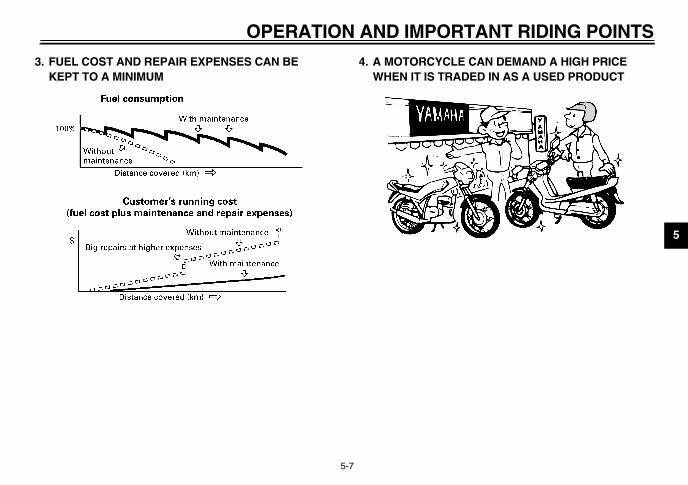
FUEL COST AND REPAIR EXPENSES CAN BE KEPT TO A MINIMUM
4. A MOTORCYCLE WHEN IT IS TRAD

6
EAU00462
TE:ou do not have the tools or experi-e required for a particular job, have
U5MXE0.book Page 1 Thursday, December 20, 2001 2:08 PM
6-PE
SafPer
amaha dealer perform it for you.
EW000063
WARNINGdifications not approved by
aha may cause loss of perfor-nce and render the vehicle un-e for use. Consult a Yamahaler before attempting any chang-
bricsafsiblspeareThemashoerationWECAUSVAEN
_
If ycycYam_
6-1
RIODIC MAINTENANCE AND MINOR REPAIR EAU00464
ety is an obligation of the owner.iodic inspection, adjustment and lu-ation will keep your vehicle in theest and most efficient condition pos-e. The most important points of in-ction, adjustment, and lubrication explained on the following pages. intervals given in the periodic
intenance and lubrication chartuld be simply considered as a gen-l guide under normal riding condi-s. However, DEPENDING ON THEATHER, TERRAIN, GEOGRAPHI-L LOCATION, AND INDIVIDUALE, THE MAINTENANCE INTER-LS MAY NEED TO BE SHORT-ED.
EW000060
WARNINGou are not familiar with motor-le maintenance work, have aaha dealer do it for you.
EAU03846*
Owner’s tool kit The owner’s tool kit is located on thebottom of the seat. (See page 3-6 forseat opening and closing procedures.)The service information included in thismanual and the tools provided in theowner’s tool kit are intended to assistyou in the performance of preventivemaintenance and minor repairs. How-ever, additional tools such as a torquewrench may be necessary to performcertain maintenance work correctly.
NO_
If yenca Y_
_
MoYammasafdeaes._
1. Owner’s tool kit
AND MINOR REPAIR
6
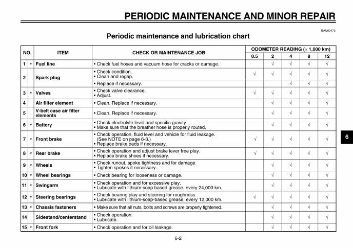
EAU00473
art CP
NODOMETER READING (× 1,000 km)
0.5 2 4 8 12
1 √ √ √ √
2√ √ √ √ √
√ √ √
3 √ √ √ √ √
4 √ √ √ √
5 √ √ √ √
6 √ √ √ √
7 √ √ √ √ √
8 √ √ √ √ √
9 √ √ √ √
10 √ √ √ √
11 √ √ √ √
12 √ √ √ √ √
13 √ √ √ √
14 √ √ √ √
15 √ √ √ √
U5MXE0.book Page 2 Thursday, December 20, 2001 2:08 PM
PERIODIC MAINTENANCE
6-2
Periodic maintenance and lubrication ch-03E
O. ITEM CHECK OR MAINTENANCE JOB
* Fuel line • Check fuel hoses and vacuum hose for cracks or damage.
Spark plug• Check condition.• Clean and regap.
• Replace if necessary.
* Valves • Check valve clearance.• Adjust.
Air filter element • Clean. Replace if necessary.
V-belt case air filter elements • Clean. Replace if necessary.
* Battery • Check electrolyte level and specific gravity.• Make sure that the breather hose is properly routed.
* Front brake• Check operation, fluid level and vehicle for fluid leakage.
(See NOTE on page 6-3.)• Replace brake pads if necessary.
* Rear brake • Check operation and adjust brake lever free play.• Replace brake shoes if necessary.
* Wheels • Check runout, spoke tightness and for damage.• Tighten spokes if necessary.
* Wheel bearings • Check bearing for looseness or damage.
* Swingarm • Check operation and for excessive play.• Lubricate with lithium-soap based grease, every 24,000 km.
* Steering bearings • Check bearing play and steering for roughness.• Lubricate with lithium-soap-based grease, every 12,000 km.
* Chassis fasteners • Make sure that all nuts, bolts and screws are properly tightened.
Sidestand/centerstand • Check operation.• Lubricate.
* Front fork • Check operation and for oil leakage.
PE
6
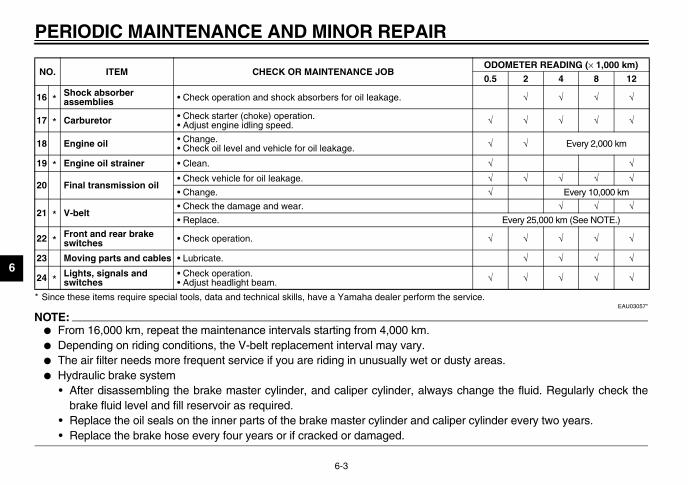
* Si ice.EAU03057*
NO_
�
�
� areas.�
ange the fluid. Regularly check the
cylinder every two years.
_
16 √ √ √ √
17 √ √ √ √ √
18 √ √ Every 2,000 km
19 √ √
20√ √ √ √ √√ Every 10,000 km
21√ √ √
Every 25,000 km (See NOTE.)
22 √ √ √ √ √
23 √ √ √ √
24 √ √ √ √ √
NOODOMETER READING (× 1,000 km)
0.5 2 4 8 12
U5MXE0.book Page 3 Thursday, December 20, 2001 2:08 PM
RIODIC MAINTENANCE AND MINOR REPAIR
6-3
nce these items require special tools, data and technical skills, have a Yamaha dealer perform the serv
TE:From 16,000 km, repeat the maintenance intervals starting from 4,000 km.Depending on riding conditions, the V-belt replacement interval may vary.The air filter needs more frequent service if you are riding in unusually wet or dustyHydraulic brake system• After disassembling the brake master cylinder, and caliper cylinder, always ch
brake fluid level and fill reservoir as required.• Replace the oil seals on the inner parts of the brake master cylinder and caliper • Replace the brake hose every four years or if cracked or damaged.
*Shock absorber assemblies • Check operation and shock absorbers for oil leakage.
* Carburetor • Check starter (choke) operation.• Adjust engine idling speed.
Engine oil • Change.• Check oil level and vehicle for oil leakage.
* Engine oil strainer • Clean.
Final transmission oil• Check vehicle for oil leakage.
• Change.
* V-belt• Check the damage and wear.
• Replace.
*Front and rear brake switches • Check operation.
Moving parts and cables • Lubricate.
*Lights, signals and switches
• Check operation.• Adjust headlight beam.
. ITEM CHECK OR MAINTENANCE JOB
AND MINOR REPAIR
6RcThneofthtimre
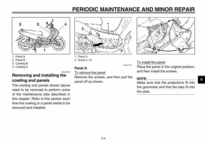
install the panelace the panel in the original position,d then install the screws.
TE:ake sure that the projections fit intoe grommets and that the tabs fit intoe slots.
1.2.3.4.
U5MXE0.book Page 4 Thursday, December 20, 2001 2:08 PM
PERIODIC MAINTENANCE
6-4
EAU03516
emoving and installing the owling and panels e cowling and panels shown aboveed to be removed to perform some
the maintenance jobs described inis chapter. Refer to this section eache the cowling or a panel needs to be
moved and installed.
EAU01074*
Panel ATo remove the panelRemove the screws, and then pull thepanel off as shown.
ToPlan
NO_
Mthth_
Panel APanel BCowling BCowling A
1. Panel A2. Screw (× 2)

PE
6
PaTo
1.
2.
ToPlaand
Remove the screws on cowling A.
1. S2. P
crew (× 2)owling A
U5MXE0.book Page 5 Thursday, December 20, 2001 2:08 PM
RIODIC MAINTENANCE AND MINOR REPAIR
6-5
EAU03971
nel B remove the panel
Open the seat. (See page 3-6 forseat opening and closing proce-dures.)Remove the screws, and then pullthe panel off as shown.
install the panelce the panel in the original position, then install the screws.
EAU03886*
Cowling A To remove the cowling
1. Remove the license plate bracketby removing the screws.
2.
crew (× 2)anel B
1. Screw (× 2)2. Cowling A3. License plate bracket
1. S2. C

AND MINOR REPAIR
6
3 install the cowling. Align the tabs in cowling A with the
slots of cowling B, and then pushcowling A into the original position.
TE:hen installing cowling A, push in one areas shown from top to bottom.
. Install the screws on cowling B.
. Install the screws on cowling A.
. Install the license plate bracket byinstalling the screws.
1.2.
U5MXE0.book Page 6 Thursday, December 20, 2001 2:08 PM
PERIODIC MAINTENANCE
6-6
. Remove the screws on cowling B.4. Pull cowling A off as shown.
NOTE:_
When removing cowling A, pull out onthe areas shown from bottom to top. _
To1
NO_
Wth_
234
Screw (× 6)Cowling B
PE
6
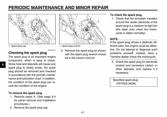
ChThcomSinspapluin ananthevea
To1.
2.
check the spark plugCheck that the porcelain insulatoraround the center electrode of thespark plug is a medium-to-light tan(the ideal color when the motor-cycle is ridden normally).
TE:e spark plug shows a distinctly dif-nt color, the engine could be defec-. Do not attempt to diagnose suchblems yourself. Instead, have a
aha dealer check the motorcycle.
Check the spark plug for electrodeerosion and excessive carbon orother deposits, and replace it ifnecessary.
1. S
pecified spark plug:CR7HSA (NGK)
U5MXE0.book Page 7 Thursday, December 20, 2001 2:08 PM
RIODIC MAINTENANCE AND MINOR REPAIR
6-7
EAUT0004*
ecking the spark plug e spark plug is an important engine
ponent, which is easy to check.ce heat and deposits will cause anyrk plug to slowly erode, the spark
g should be removed and checkedccordance with the periodic mainte-ce and lubrication chart. In addition, condition of the spark plug can re-l the condition of the engine.
remove the spark plugRemove panel A. (See page 6-4for panel removal and installationprocedures.)Remove the spark plug cap.
3. Remove the spark plug as shown,with the spark plug wrench includ-ed in the owner’s tool kit.
To 1.
NO_
If thferetiveproYam_
2.
park plug cap 1. Spark plug wrench
S
AND MINOR REPAIR
6
To1
2
3
a.
U5MXE0.book Page 8 Thursday, December 20, 2001 2:08 PM
PERIODIC MAINTENANCE
6-8
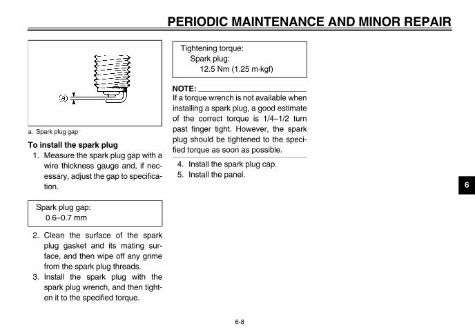
install the spark plug. Measure the spark plug gap with a
wire thickness gauge and, if nec-essary, adjust the gap to specifica-tion.
. Clean the surface of the sparkplug gasket and its mating sur-face, and then wipe off any grimefrom the spark plug threads.
. Install the spark plug with thespark plug wrench, and then tight-en it to the specified torque.
NOTE:_
If a torque wrench is not available wheninstalling a spark plug, a good estimateof the correct torque is 1/4–1/2 turnpast finger tight. However, the sparkplug should be tightened to the speci-fied torque as soon as possible. _
4. Install the spark plug cap.5. Install the panel.
Spark plug gap
Spark plug gap:0.6–0.7 mm
Tightening torque:Spark plug:
12.5 Nm (1.25 m·kgf)
PE
6
EnThbefmuclepercha
To1.
NO_
Mationleva fa_
2.
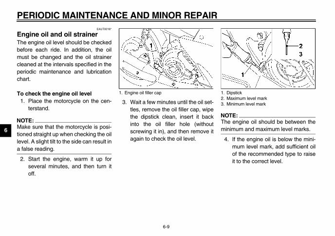
TE: engine oil should be between theimum and maximum level marks.
If the engine oil is below the mini-mum level mark, add sufficient oilof the recommended type to raiseit to the correct level.
ipstickaximum level markinimum level mark
U5MXE0.book Page 9 Thursday, December 20, 2001 2:08 PM
RIODIC MAINTENANCE AND MINOR REPAIR
6-9
EAUT0016*
gine oil and oil strainer e engine oil level should be checkedore each ride. In addition, the oilst be changed and the oil straineraned at the intervals specified in theiodic maintenance and lubricationrt.
check the engine oil levelPlace the motorcycle on the cen-terstand.
TE:ke sure that the motorcycle is posi-ed straight up when checking the oil
el. A slight tilt to the side can result inlse reading.
Start the engine, warm it up forseveral minutes, and then turn itoff.
3. Wait a few minutes until the oil set-tles, remove the oil filler cap, wipethe dipstick clean, insert it backinto the oil filler hole (withoutscrewing it in), and then remove itagain to check the oil level.
NO_
Themin_
4.
1. Engine oil filler cap 1. D2. M3. M
AND MINOR REPAIR
6
Toth
1
2
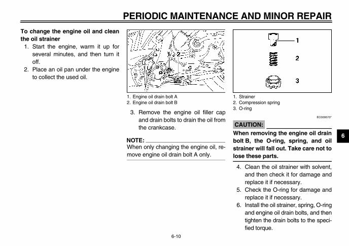
EC000070*
AUTION:hen removing the engine oil drainlt B, the O-ring, spring, and oil
rainer will fall out. Take care not tose these parts.
. Clean the oil strainer with solvent,and then check it for damage andreplace it if necessary.
. Check the O-ring for damage andreplace it if necessary.
. Install the oil strainer, spring, O-ringand engine oil drain bolts, and thentighten the drain bolts to the speci-fied torque.
StrainerCompression springO-ring
U5MXE0.book Page 10 Thursday, December 20, 2001 2:08 PM
PERIODIC MAINTENANCE
6-10
change the engine oil and cleane oil strainer. Start the engine, warm it up for
several minutes, and then turn itoff.
. Place an oil pan under the engineto collect the used oil.
3. Remove the engine oil filler capand drain bolts to drain the oil fromthe crankcase.
NOTE:_
When only changing the engine oil, re-move engine oil drain bolt A only. _
C_
Wbostlo_
4
5
6
1. Engine oil drain bolt A2. Engine oil drain bolt B
1.2.3.
PE
6
NO_
Masea_
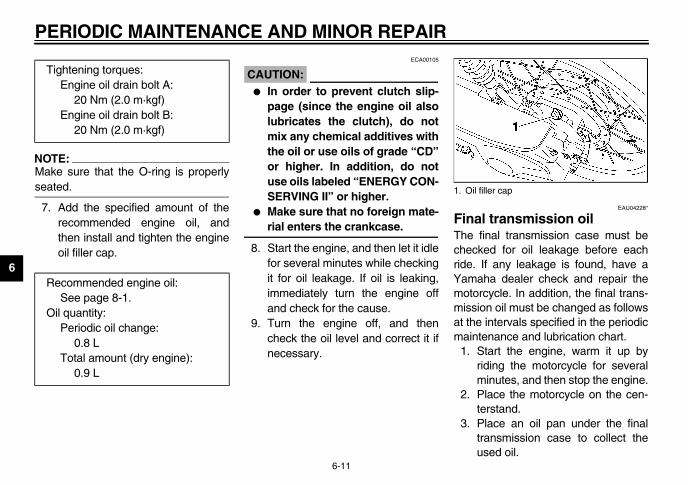
7. EAU04228*
al transmission oil final transmission case must beked for oil leakage before each
. If any leakage is found, have aaha dealer check and repair the
orcycle. In addition, the final trans-ion oil must be changed as followse intervals specified in the periodictenance and lubrication chart.Start the engine, warm it up byriding the motorcycle for severalminutes, and then stop the engine.Place the motorcycle on the cen-terstand.Place an oil pan under the finaltransmission case to collect theused oil.
T
R
O
il filler cap
U5MXE0.book Page 11 Thursday, December 20, 2001 2:08 PM
RIODIC MAINTENANCE AND MINOR REPAIR
6-11
TE:ke sure that the O-ring is properlyted.
Add the specified amount of therecommended engine oil, andthen install and tighten the engineoil filler cap.
ECA00105
CAUTION:_
� In order to prevent clutch slip-page (since the engine oil alsolubricates the clutch), do notmix any chemical additives withthe oil or use oils of grade “CD”or higher. In addition, do notuse oils labeled “ENERGY CON-SERVING II” or higher.
� Make sure that no foreign mate-rial enters the crankcase.
_
8. Start the engine, and then let it idlefor several minutes while checkingit for oil leakage. If oil is leaking,immediately turn the engine offand check for the cause.
9. Turn the engine off, and thencheck the oil level and correct it ifnecessary.
FinThechecrideYammotmissat thmain
1.
2.
3.
ightening torques:Engine oil drain bolt A:
20 Nm (2.0 m·kgf)Engine oil drain bolt B:
20 Nm (2.0 m·kgf)
ecommended engine oil:See page 8-1.
il quantity:Periodic oil change:
0.8 LTotal amount (dry engine):
0.9 L
1. O

AND MINOR REPAIR
6
4.
5.
6.
1. F
T
U5MXE0.book Page 12 Thursday, December 20, 2001 2:08 PM
PERIODIC MAINTENANCE
6-12
Remove the oil filler cap and drainbolt to drain the oil from the finaltransmission case.Install the final transmission oildrain bolt, and then tighten it to thespecified torque.
Add the specified amount of therecommended final transmissionoil, and then install and tighten theoil filler cap.
EWA00062
WARNING_
� Make sure that no foreign mate-rial enters the final transmis-sion case.
� Make sure that no oil gets onthe tire or wheel.
_
7. Check the final transmission casefor oil leakage. If oil is leaking,check for the cause.
inal transmission oil drain bolt
ightening torque:Final transmission oil drain bolt:
22 Nm (2.2 m·kgf)
Recommended final transmission oil:
See page 8-1.Oil quantity:
0.1 L
PE
6
ClV-anThter intetenbotyouarehoscle
Cle1.
2.
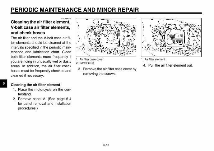
Pull the air filter element out.
ir filter element
U5MXE0.book Page 13 Thursday, December 20, 2001 2:08 PM
RIODIC MAINTENANCE AND MINOR REPAIR
6-13
EAUM0058*
eaning the air filter element, belt case air filter elements, d check hoses e air filter and the V-belt case air fil-elements should be cleaned at thervals specified in the periodic main-ance and lubrication chart. Cleanh filter elements more frequently if are riding in unusually wet or dustyas. In addition, the air filter checkes must be frequently checked and
aned if necessary.
aning the air filter elementPlace the motorcycle on the cen-terstand.Remove panel A. (See page 6-4for panel removal and installationprocedures.)
3. Remove the air filter case cover byremoving the screws.
4.
1. Air filter case cover2. Screw (× 5)
1. A
AND MINOR REPAIR
6
5
6
7
8
9
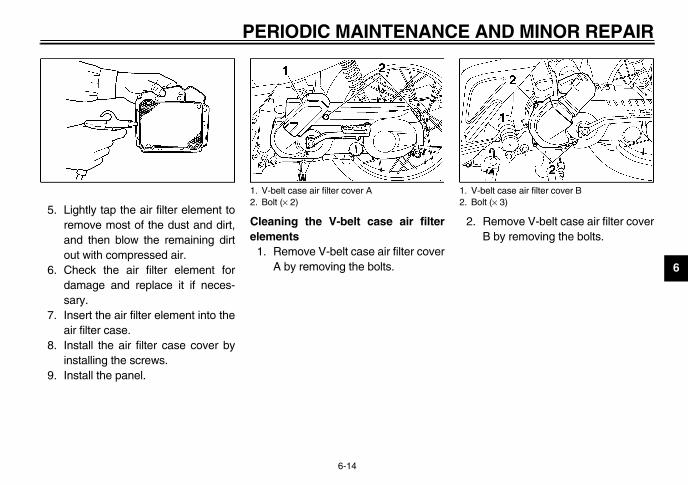
. Remove V-belt case air filter coverB by removing the bolts.
V-belt case air filter cover BBolt (× 3)
U5MXE0.book Page 14 Thursday, December 20, 2001 2:08 PM
PERIODIC MAINTENANCE
6-14
. Lightly tap the air filter element toremove most of the dust and dirt,and then blow the remaining dirtout with compressed air.
. Check the air filter element fordamage and replace it if neces-sary.
. Insert the air filter element into theair filter case.
. Install the air filter case cover byinstalling the screws.
. Install the panel.
Cleaning the V-belt case air filterelements
1. Remove V-belt case air filter coverA by removing the bolts.
2
1. V-belt case air filter cover A2. Bolt (× 2)
1.2.
PE
6
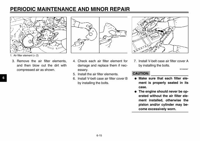
3. Install V-belt case air filter cover Aby installing the bolts.
EC000092*
UTION:Make sure that each filter ele-ment is properly seated in itscase.The engine should never be op-erated without the air filter ele-ment installed, otherwise thepiston and/or cylinder may be-come excessively worn.
1. A
U5MXE0.book Page 15 Thursday, December 20, 2001 2:08 PM
RIODIC MAINTENANCE AND MINOR REPAIR
6-15
Remove the air filter elements,and then blow out the dirt withcompressed air as shown.
4. Check each air filter element fordamage and replace them if nec-essary.
5. Install the air filter elements.6. Install V-belt case air filter cover B
by installing the bolts.
7.
CA_
�
�
_
ir filter element (× 2)
AND MINOR REPAIR
6
To1
EAU00629
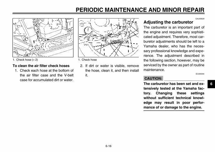
djusting the carburetor e carburetor is an important part of
e engine and requires very sophisti-ted adjustment. Therefore, most car-retor adjustments should be left to amaha dealer, who has the neces-ry professional knowledge and expe-nce. The adjustment described ine following section, however, may berviced by the owner as part of routineaintenance.
EC000094
AUTION:e carburetor has been set and ex-
nsively tested at the Yamaha fac-ry. Changing these settingsithout sufficient technical knowl-ge may result in poor perfor-ance of or damage to the engine.
1.
U5MXE0.book Page 16 Thursday, December 20, 2001 2:08 PM
PERIODIC MAINTENANCE
6-16
clean the air filter check hoses. Check each hose at the bottom of
the air filter case and the V-beltcase for accumulated dirt or water.
2. If dirt or water is visible, removethe hose, clean it, and then installit.
AThthcabuYasariethsem
C_
Thtetowedm_
Check hose (× 2) 1. Check hose
PE
6
AdspThchefollpercha
NO_
A dma_
1.
2.
NO_
Thspo_
EAU00634*
justing the throttle cable e play throttle cable free play should
asure 3–7 mm at the throttle grip.iodically check the throttle cable play and, if necessary, adjust it asws.
TE: engine idling speed must be cor-
tly adjusted before checking and ad-ting the throttle cable free play.
U5MXE0.book Page 17 Thursday, December 20, 2001 2:08 PM
RIODIC MAINTENANCE AND MINOR REPAIR
6-17
EAU01168
justing the engine idling eed e engine idling speed must becked and, if necessary, adjusted as
ows at the intervals specified in theiodic maintenance and lubricationrt.
TE:iagnostic tachometer is needed toke this adjustment.
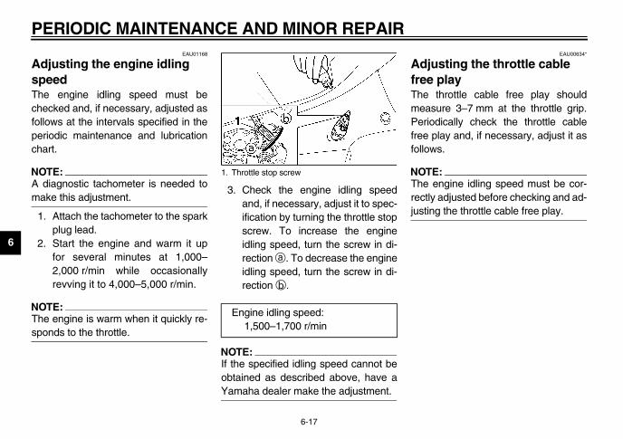
Attach the tachometer to the sparkplug lead.Start the engine and warm it upfor several minutes at 1,000–2,000 r/min while occasionallyrevving it to 4,000–5,000 r/min.
TE:e engine is warm when it quickly re-nds to the throttle.
3. Check the engine idling speedand, if necessary, adjust it to spec-ification by turning the throttle stopscrew. To increase the engineidling speed, turn the screw in di-rection a. To decrease the engineidling speed, turn the screw in di-rection b.
NOTE:_
If the specified idling speed cannot beobtained as described above, have aYamaha dealer make the adjustment. _
AdfreThemePerfreefollo
NO_
Therecjus_
1. Throttle stop screw
Engine idling speed:1,500–1,700 r/min

ND MINOR REPAIR
6
1.2.
3.
NO_
Aftsurorig_
1. T2. L3. Cc. T
U5MXE0.book Page 18 Thursday, December 20, 2001 2:08 PM
PERIODIC MAINTENANCE A
6-18
Loosen the locknut.To increase the throttle cable freeplay, turn the adjusting nut in di-rection a. To decrease the throttlecable free play, turn the adjustingnut in direction b.Tighten the locknut.
TE:er adjusting the throttle free play, bee to place the cable cover in theinal position.
EAU00637
Adjusting the valve clearance The valve clearance changes with use,resulting in improper air-fuel mixtureand/or engine noise. To prevent thisfrom occurring, the valve clearancemust be adjusted by a Yamaha dealerat the intervals specified in the periodicmaintenance and lubrication chart.
hrottle cable free play adjusting nutocknutable coverhrottle cable free play

PE
6
TirToity,cycreg
TirThchebef
_
Thch(i.etiretur_
EW000087
WARNINGuse loading has an enormousct on the handling, braking, per-ance and safety characteristicsur motorcycle, you should keepollowing precautions in mind. NEVER OVERLOAD THEMOTORCYCLE! Operation of anoverloaded motorcycle may re-sult in tire damage, loss of con-trol, or severe injury. Make surethat the total weight of rider, pas-senger, cargo, and accessoriesdoes not exceed the specifiedmaximum load for the vehicle. Do not carry along looselypacked items, which can shiftduring a ride. Securely pack the heaviestitems close to the center of themotorcycle and distribute theweight evenly on both sides. Adjust the tire air pressure withregard to the load. Check the tire condition and airpressure before each ride.
U5MXE0.book Page 19 Thursday, December 20, 2001 2:08 PM
RIODIC MAINTENANCE AND MINOR REPAIR
6-19
EAU03790*
es maximize the performance, durabil- and safe operation of your motor-le, note the following pointsarding the specified tires.
e air pressuree tire air pressure should becked and, if necessary, adjustedore each ride.
EW000091
WARNINGe tire air pressure must beecked and adjusted on cold tires., when the temperature of thes equals the ambient tempera-e).
CE-24E
CE-07E
_
Becaimpaformof yothe f
�
�
�
�
�
_
Tire air pressure(measured on cold tires)
Front Rear
200 kPa(2.00 kgf/cm2)
225 kPa(2.25 kgf/cm2)
Maximum load* 116 kg
* Total weight of rider, passenger, cargo and accessories

ND MINOR REPAIR
6
TirThride(mnaisiddeaCE-2
NO_
Thfrowit_
informationmotorcycle is equipped with tube
EW000078
WARNINGhe front and rear tires shoulde of the same make and de-ign, otherwise the handlingharacteristics of the motor-ycle cannot be guaranteed.fter extensive tests, only the
ires listed below have been ap-roved for this model byamaha Motor Co., Ltd.
1. S2. Ta. T
M(fr
facturer Size Model
p 70/90-16 36P D110
facturer Size Model
p 80/90-16 43P D110
U5MXE0.book Page 20 Thursday, December 20, 2001 2:08 PM
PERIODIC MAINTENANCE A
6-20
e inspectione tires must be checked before each. If the tire shows crosswise lines
inimum tread depth), if the tire has al or glass fragments in it, or if theewall is cracked, have a Yamahaler replace the tire immediately.
3E
TE:e tire tread depth limits may differm country to country. Always complyh the local regulations.
EW000079
WARNING_
� Have a Yamaha dealer replaceexcessively worn tires. Besidesbeing illegal, operating themotorcycle with excessivelyworn tires decreases riding sta-bility and can lead to loss ofcontrol.
� The replacement of all wheel-and brake-related parts, includ-ing the tires, should be left to aYamaha dealer, who has thenecessary professional knowl-edge and experience.
_
Tire This tires.
_
� Tbscc
� AtpY
_
CE-10E
idewallire wear indicatorire tread depth
inimum tire tread depth ont and rear)
1.0 mm
FRONT
Manu
Dunlo
REAR
Manu
Dunlo

PE
6
_
�
�
�
_
EAU03851*
ecking the front brake lever e playce this model is equipped with a hy-ulic front brake, adjusting the brakeer free play is not needed.wever, it is necessary to check theke fluid level and check the hydrau-ystem for leakage.
ront brake lever
U5MXE0.book Page 21 Thursday, December 20, 2001 2:08 PM
RIODIC MAINTENANCE AND MINOR REPAIR
6-21
EAU00680
WARNINGIt is dangerous to ride with aworn-out tire. When a tire treadbegins to show crosswise lines,have a Yamaha dealer replacethe tire immediately.The replacement of all wheel-and brake-related parts, includ-ing the tires, should be left to aYamaha dealer, who has thenecessary professional knowl-edge and experience.It is not recommended to patcha punctured tube. If unavoid-able, however, patch the tubevery carefully and replace it assoon as possible with a high-quality product.
EAU00685
Spoke wheels To maximize the performance, durabil-ity, and safe operation of your motor-cycle, note the following pointsregarding the specified wheels.
� The wheel rims should be checkedfor cracks, bends or warpage, andthe spokes for looseness or dam-age before each ride. If any dam-age is found, have a Yamahadealer replace the wheel. Do notattempt even the smallest repair tothe wheel. A deformed or crackedwheel must be replaced.
� The wheel should be balancedwhenever either the tire or wheelhas been changed or replaced. Anunbalanced wheel can result inpoor performance, adverse han-dling characteristics, and a short-ened tire life.
� Ride at moderate speeds afterchanging a tire since the tire sur-face must first be “broken in” for itto develop its optimal characteris-tics.
ChfreSindralevHobralic s
1. F

AND MINOR REPAIR
6
_
AleaiisYfoththmac_
increase the rear brake lever freeay, turn the adjusting nut at the brakeoe plate in direction a. To decreasee rear brake lever free play, turn thejusting nut in direction b.
EW000101
WARNINGproper adjustment cannot be ob-ined as described, have a Yamahaaler make this adjustment.
Rear brake lever free play adjusting nut
U5MXE0.book Page 22 Thursday, December 20, 2001 2:08 PM
PERIODIC MAINTENANCE
6-22
EW000099*
WARNING soft or spongy feeling in the brakever can indicate the presence ofr in the hydraulic system. If there air in the hydraulic system, have aamaha dealer bleed the system be-re operating the motorcycle. Air ine hydraulic system will diminishe braking performance, whichay result in loss of control and ancident.
EAU00704*
Adjusting the rear brake lever free play The rear brake lever free play shouldmeasure 10–20 mm as shown. Period-ically check the rear brake lever freeplay and, if necessary, adjust it as fol-lows.
Toplshthad
_
If tade_
a. Rear brake lever free play 1.
PE
6
ChanThbraat tma
EAU04502
ar brake shoes rear brake is provided with a wear
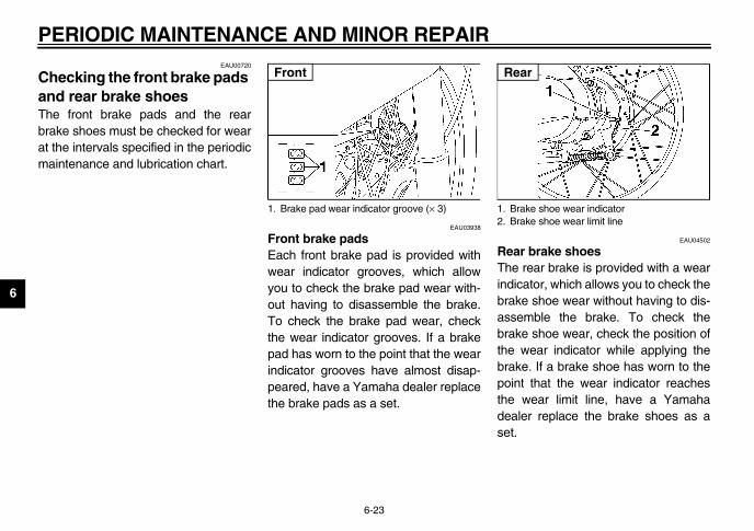
icator, which allows you to check theke shoe wear without having to dis-emble the brake. To check theke shoe wear, check the position of wear indicator while applying theke. If a brake shoe has worn to thent that the wear indicator reaches wear limit line, have a Yamahaler replace the brake shoes as a
.
rake shoe wear indicatorrake shoe wear limit line
ar
U5MXE0.book Page 23 Thursday, December 20, 2001 2:08 PM
RIODIC MAINTENANCE AND MINOR REPAIR
6-23
EAU00720
ecking the front brake pads d rear brake shoes e front brake pads and the rearke shoes must be checked for wearhe intervals specified in the periodicintenance and lubrication chart.
EAU03938
Front brake padsEach front brake pad is provided withwear indicator grooves, which allowyou to check the brake pad wear with-out having to disassemble the brake.To check the brake pad wear, checkthe wear indicator grooves. If a brakepad has worn to the point that the wearindicator grooves have almost disap-peared, have a Yamaha dealer replacethe brake pads as a set.
ReTheindbraassbrathebrapoithedeaset
1. Brake pad wear indicator groove (× 3)
Front
1. B2. B
Re

AND MINOR REPAIR
6
CIneninBisreidanbrbrte
� Brake fluid may deteriorate paint-ed surfaces or plastic parts. Al-ways clean up spilled fluidimmediately.
� As the brake pads wear, it is nor-mal for the brake fluid level togradually go down. However, if thebrake fluid level goes down sud-denly, have a Yamaha dealercheck the cause.
1.
U5MXE0.book Page 24 Thursday, December 20, 2001 2:08 PM
PERIODIC MAINTENANCE
6-24
EAU00732
hecking the brake fluid level sufficient brake fluid may allow air toter the brake system, possibly caus-
g it to become ineffective.efore riding, check that the brake fluid above the minimum level mark andplenish if necessary. A low brake flu- level may indicate worn brake padsd/or brake system leakage. If theake level is low, be sure to check theake pads for wear and the brake sys-m for leakage.
Observe these precautions:� When checking the fluid level,
make sure that the top of the mas-ter cylinder is level by turning thehandlebars.
� Use only the recommended quali-ty brake fluid, otherwise the rubberseals may deteriorate, causingleakage and poor braking perfor-mance.
NOTE:_
If DOT 4 is not available, DOT 3 can beused. _
� Refill with the same type of brakefluid. Mixing fluids may result in aharmful chemical reaction andlead to poor braking performance.
� Be careful that water does not en-ter the master cylinder when refill-ing. Water will significantly lowerthe boiling point of the fluid andmay result in vapor lock.
Minimum level mark
Recommended brake fluid: DOT 4

PE
6
ChHabrathenanhavcylbralistage
�
�
EAU02962
ecking and lubricating the bles operation of all control cables and
condition of the cables should becked before each ride, and the ca-
s and cable ends should be lubricat-if necessary. If a cable is damageddoes not move smoothly, have a
aha dealer check or replace it.
EW000112
WARNINGmage to the outer sheath may in-fere with proper cable operation will cause the inner cable tot. Replace a damaged cable asn as possible to prevent unsafeditions.
ecommended lubricant:Engine oil
U5MXE0.book Page 25 Thursday, December 20, 2001 2:08 PM
RIODIC MAINTENANCE AND MINOR REPAIR
6-25
EAU03985
anging the brake fluid ve a Yamaha dealer change theke fluid at the intervals specified in NOTE after the periodic mainte-ce and lubrication chart. In addition,e the oil seals of the brake master
inder and caliper as well as theke hose replaced at the intervalsed below or whenever they are dam-d or leaking.Oil seals: Replace every twoyears.Brake hose: Replace every fouryears.
EAU00770*
Checking the V-belt The V-belt must be checked by aYamaha dealer at the intervals speci-fied in the periodic maintenance and lu-brication chart.
NOTE:_
It is recommended to replace the V-beltevery 25,000 km. _
ChcaThethechebleed or Yam
_
Daterandrussoocon_
R

AND MINOR REPAIR
6
CthThbetioreth
U5MXE0.book Page 26 Thursday, December 20, 2001 2:08 PM
PERIODIC MAINTENANCE
6-26
EAU04034
hecking and lubricating the rottle grip and cable e operation of the throttle grip should checked before each ride. In addi-n, the cable should be lubricated orplaced at the intervals specified ine periodic maintenance chart.
EAU03118
Lubricating the front and rear brake levers The pivoting points of the front and rearbrake levers must be lubricated at theintervals specified in the periodic main-tenance and lubrication chart.
Recommended lubricant:Lithium-soap-based grease (all-purpose grease)

PE
6
ChceThsideacmecat
_
If tnohapa_
EAU02939
ecking the front fork condition and operation of the front must be checked as follows at thervals specified in the periodic main-ance and lubrication chart.
check the conditionEW000115
WARNINGurely support the motorcycle sot there is no danger of it fallingr.
eck the inner tubes for scratches,age and excessive oil leakage.
U5MXE0.book Page 27 Thursday, December 20, 2001 2:08 PM
RIODIC MAINTENANCE AND MINOR REPAIR
6-27
EAU03371
ecking and lubricating the nterstand and sidestand e operation of the centerstand andestand should be checked beforeh ride, and the pivots and metal-to-tal contact surfaces should be lubri-ed if necessary.
EW000114
WARNINGhe centerstand or sidestand doest move up and down smoothly,ve a Yamaha dealer check or re-ir it.
ChTheforkinteten
To
_
Secthaove_
Chdam
Recommended lubricant:Lithium-soap-based grease (all-purpose grease)
AND MINOR REPAIR
6
To1
2
C_
If fohapa_
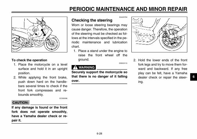
. Hold the lower ends of the frontfork legs and try to move them for-ward and backward. If any freeplay can be felt, have a Yamahadealer check or repair the steer-ing.
U5MXE0.book Page 28 Thursday, December 20, 2001 2:08 PM
PERIODIC MAINTENANCE
6-28
check the operation. Place the motorcycle on a level
surface and hold it in an uprightposition.
. While applying the front brake,push down hard on the handle-bars several times to check if thefront fork compresses and re-bounds smoothly.
EC000098
AUTION:any damage is found or the frontrk does not operate smoothly,ve a Yamaha dealer check or re-ir it.
EAU00794
Checking the steering Worn or loose steering bearings maycause danger. Therefore, the operationof the steering must be checked as fol-lows at the intervals specified in the pe-riodic maintenance and lubricationchart.
1. Place a stand under the engine toraise the front wheel off theground.
EW000115
WARNING_
Securely support the motorcycle sothat there is no danger of it fallingover. _
2

PE
6
ChThbe thetionhubsmche
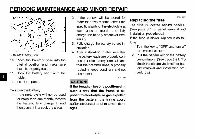
Unhook the battery band, and thendisconnect the negative batterylead from the battery.Pull the battery breather hose outas shown.Pull the battery out of the batterycompartment.
egative battery leadattery bandattery breather hose
U5MXE0.book Page 29 Thursday, December 20, 2001 2:08 PM
RIODIC MAINTENANCE AND MINOR REPAIR
6-29
EAU01144
ecking the wheel bearings e front and rear wheel bearings mustchecked at the intervals specified in periodic maintenance and lubrica- chart. If there is play in the wheel or if the wheel does not turn
oothly, have a Yamaha dealerck the wheel bearings.
EAU03806*
Battery A poorly maintained battery will cor-rode and discharge quickly. The elec-trolyte level, battery lead connectionsand breather hose routing should bechecked before each ride and at the in-tervals specified in the periodic mainte-nance and lubrication chart.
To check the electrolyte level1. Remove panel A. (See page 6-4
for panel removal and installationprocedures.)
2.
3.
4.
1. N2. B3. B

AND MINOR REPAIR
6
5
N_
Thm_
6
� KEEP THIS AND ALL BATTER-IES OUT OF THE REACH OFCHILDREN.
EC000100
AUTION:e only distilled water, as tap waterntains minerals that are harmful the battery.
. Check and, if necessary, tightenthe positive battery lead to thepositive battery terminal.
. Place the battery in the batterycompartment.
. Connect and tighten the negativebattery lead to the negative batteryterminal.
1.2.
U5MXE0.book Page 30 Thursday, December 20, 2001 2:08 PM
PERIODIC MAINTENANCE
6-30
. Place the battery on a level sur-face, and then check the electro-lyte level in the battery.
OTE:e electrolyte should be between the
inimum and maximum level marks.
. If the electrolyte is at or below theminimum level mark, add distilledwater to raise the electrolyte to themaximum level mark.
EW000116
WARNING_
� Electrolyte is poisonous anddangerous since it contains sul-furic acid, which causes severeburns. Avoid any contact withskin, eyes or clothing and al-ways shield your eyes whenworking near batteries. In caseof contact, administer the fol-lowing FIRST AID.• EXTERNAL: Flush with plenty
of water.• INTERNAL: Drink large quan-
tities of water or milk and im-mediately call a physician.
• EYES: Flush with water for15 minutes and seek promptmedical attention.
� Batteries produce explosive hy-drogen gas. Therefore, keepsparks, flames, cigarettes, etc.,away from the battery and pro-vide sufficient ventilation whencharging it in an enclosedspace.
_
C_
Uscoto_
7
8
9
Maximum level markMinimum level mark
PE
6
10.
11.
12.
To1.
EAU01307*
placing the fuse fuse is located behind panel A.e page 6-4 for panel removal andtallation procedures.)e fuse is blown, replace it as fol-
s.Turn the key to “OFF” and turn offall electrical circuits.Pull the battery out of the batterycompartment. (See page 6-29, “Tocheck the electrolyte level” for bat-tery removal and installation pro-cedures.)
1. B
U5MXE0.book Page 31 Thursday, December 20, 2001 2:08 PM
RIODIC MAINTENANCE AND MINOR REPAIR
6-31
Place the breather hose into theoriginal position and make surethat it is properly routed.Hook the battery band onto theholder.Install the panel.
store the batteryIf the motorcycle will not be usedfor more than one month, removethe battery, fully charge it, andthen place it in a cool, dry place.
2. If the battery will be stored formore than two months, check thespecific gravity of the electrolyte atleast once a month and fullycharge the battery whenever nec-essary.
3. Fully charge the battery before in-stallation.
4. After installation, make sure thatthe battery leads are properly con-nected to the battery terminals andthat the breather hose is properlyrouted, in good condition, and notobstructed.
EC000099
CAUTION:_
If the breather hose is positioned insuch a way that the frame is ex-posed to electrolyte or gas expelledfrom the battery, the frame couldsuffer structural and external dam-ages. _
ReThe(SeinsIf thlow
1.
2.attery breather hose
AND MINOR REPAIR
6
3
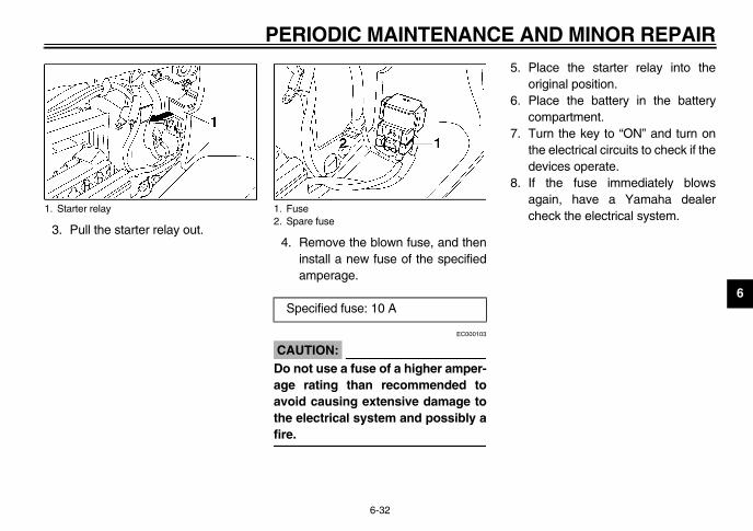
. Place the starter relay into theoriginal position.
. Place the battery in the batterycompartment.
. Turn the key to “ON” and turn onthe electrical circuits to check if thedevices operate.
. If the fuse immediately blowsagain, have a Yamaha dealercheck the electrical system.
1.
U5MXE0.book Page 32 Thursday, December 20, 2001 2:08 PM
PERIODIC MAINTENANCE
6-32
. Pull the starter relay out.4. Remove the blown fuse, and then
install a new fuse of the specifiedamperage.
EC000103
CAUTION:_
Do not use a fuse of a higher amper-age rating than recommended toavoid causing extensive damage tothe electrical system and possibly afire. _
5
6
7
8
Starter relay 1. Fuse2. Spare fuse
Specified fuse: 10 A

PE
6
ReIf aas
CA_
It de_
1.
2. Remove the socket by pushing itin and turning it counterclockwise.Remove the defective bulb.
EW000119
WARNINGadlight bulbs get very hot. There-e, keep flammable products awaym a lit headlight bulb, and do notch the bulb until it has cooledn.
Place a new headlight bulb intoposition.Install the socket by pushing it inand turning it clockwise.
eadlight bulb socket (× 2)
U5MXE0.book Page 33 Thursday, December 20, 2001 2:08 PM
RIODIC MAINTENANCE AND MINOR REPAIR
6-33
EAU04134*
placing a headlight bulb headlight bulb burns out, replace itfollows.
EC000107
UTION:is advisable to have a Yamahaaler perform this job.
Place the motorcycle on the cen-terstand.Remove cowling A. (See page 6-5for cowling removal and installa-tion procedures.)
3. Remove the headlight bulb coverby turning it counterclockwise.
4.
5.
_
Heforfrotoudow_
6.
7.
1. Headlight bulb cover (× 2) 1. H

AND MINOR REPAIR
6
8
910
. Remove the socket (together withthe bulb) by turning it counter-clockwise.
. Remove the defective bulb.
. Insert a new bulb into position.
. Install the socket (together withthe bulb) by turning it clockwise.
. Install the cowling.
Turn signal light bulb socket (× 2)
U5MXE0.book Page 34 Thursday, December 20, 2001 2:08 PM
PERIODIC MAINTENANCE
6-34
. Install the headlight bulb cover byturning it clockwise.
. Install the cowling.
. Have a Yamaha dealer adjust theheadlight beam if necessary.
EAUT0022*
Replacing a front turn signal light bulb
EC000107
CAUTION:_
It is advisable to have a Yamahadealer perform this job. _
1. Place the motorcycle on the cen-terstand.
2. Remove cowling A. (See page 6-5for cowling removal and installa-tion procedures.)
3
456
7
1.

PE
6
Rebubu
CA_
It de_
Plasta
Ta1.
Remove the defective bulb bypushing it in and turning it counter-clockwise.Insert a new bulb into the socket,push it in, and then turn it clock-wise until it stops.Place the tail/brake light lens intothe original position, and then in-stall the screws.
EC000108
UTION: not overtighten the screws, oth-ise the lens may break.
Install the panel.
1. S ail/brake light bulb
U5MXE0.book Page 35 Thursday, December 20, 2001 2:08 PM
RIODIC MAINTENANCE AND MINOR REPAIR
6-35
EAUS0013*
placing the tail/brake light lb or a rear turn signal light lb
EC000107
UTION:is advisable to have a Yamahaaler perform this job.
ce the motorcycle on the center-nd.
il/brake light bulbRemove panel B. (See page 6-5for panel removal and installationprocedures.)
2. Remove the screws, unhook thetab from the slot, and then pull thetail/brake light lens outward.
3.
4.
5.
CA_
Doerw_
6.
crew (× 2) 1. Tab2. Slot
1. T

AND MINOR REPAIR
6
Tu1
. Remove the defective bulb.
. Insert a new bulb into position.
. Place the turn signal light lens intothe original position.
. Install the tail/brake light lens.
Turn signal light bulb (× 2)
U5MXE0.book Page 36 Thursday, December 20, 2001 2:08 PM
PERIODIC MAINTENANCE
6-36
rn signal light bulb. Remove the tail/brake light lens.
(See “Tail/brake light bulb” for lensremoval and installation proce-dures.)
2. Pull the turn signal light lens off. 345
6
1.

PE
6
EAU01008
ubleshooting ough Yamaha motorcycles receiveorough inspection before shipment the factory, trouble may occur dur-
operation. Any problem in the fuel,pression, or ignition systems, formple, can cause poor starting and
s of power. following troubleshooting chartresents a quick and easy procedurechecking these vital systems your-. However, should your motorcycleuire any repair, take it to a Yamahaler, whose skilled technicians have
necessary tools, experience, andw-how to service the motorcycleperly. only genuine Yamaha replace-
nt parts. Imitation parts may look Yamaha parts, but they are oftenrior, have a shorter service life and lead to expensive repair bills.
U5MXE0.book Page 37 Thursday, December 20, 2001 2:08 PM
RIODIC MAINTENANCE AND MINOR REPAIR
6-37
TroAltha thfromingcomexalosTherepfor selfreqdeatheknoproUsemelikeinfecan

AND MINOR REPAIR
6
EAU03473
TroubleshootEW000125
WARNING_
Keep away open ystem. _
CT-1FE
1. Fu
art..
The engine does not start. Have a Yamaha dealer check the vehicle.
The engine does not start.Check the battery.
Open the throttle halfway and operate the electric starter.
U5MXE0.book Page 38 Thursday, December 20, 2001 2:08 PM
Check the futhe fuel tank
Operate theelectric starte
2. Comp
Remove the and check el
3. Ignitio
Operate theelectric start
4. Batter
PERIODIC MAINTENANCE
6-38
ing chart
flames and do not smoke while checking or working on the fuel s
el level in .
elThere isenough fuel.
There isno fuel.
Check the compression.
Supply fuel. The engine does not stCheck the compression
r.
ressionThere is compression.
There is no compression.
Check the ignition.
Have a Yamaha dealer check the vehicle.
spark plug ectrodes.
nWet
Dry
Wipe off with a dry cloth and correct the spark plug gap, or replace the spark plug.
Have a Yamaha dealer check the vehicle.
er.
yThe engine turns overquickly.
The engine turns overslowly.
The battery is good.
Check fluid, recharge, check connections.

7
EAK00000
Remove the battery and charge it.Store it in a dry place and re-charge it once a month. Do not
U5MXE0.book Page 1 Thursday, December 20, 2001 2:08 PM
7-M
A. Fre
store the battery in an excessivelywarm or cold place (less than 0 °Cor more than 30 °C).
EUU05800
TE:ke any necessary repairs beforering the motorcycle.
mopeaperof m
1.
CA_
Excwawhtranpar
2.
3.
7-1
OTORCYCLE CLEANING AND STORAGEEAK01302*
CLEANINGquent, thorough cleaning of yourtorcycle will not only enhance its ap-rance but will improve its generalformance and extend the useful lifeany components.Rinse the dirt and degreaser offwith a garden hose.
EUU34602
UTION:essive hose pressure may cause
ter seepage and deterioration ofeel bearings, front fork, brakes,smission seals and electrical
ts.
After cleaning the motorcycle, dryall surfaces with a chamois, cleantowel, or soft absorbent cloth.Automotive-type wax may be ap-plied to all painted and chrome-plated surfaces. When finished,start the engine and let it idle forseveral minutes.
EAK00700*
B. STORAGELong term storage (60 days or more) ofyour motorcycle will require some pre-ventive procedures to guard againstdeterioration. After thoroughly cleaningthe motorcycle, prepare for storage asfollows:
1. Drain the fuel tank, fuel lines, andcarburetor float bowl(s).
2. Lubricate all control cables.3. Block up the frame to raise both
wheels off the ground.4. Tie a plastic bag over the exhaust
pipe outlet to prevent moisturefrom entering.
5. If storing in a humid or salt-air at-mosphere, coat all exposed metalsurfaces with a light film of oil. Donot apply oil to any rubber parts orthe seat cover.
6.
NO_
Masto

8
8-SPECIFICATIONS
SAE 20W-50 API Service “SF” type motor oil
0.8 L
engine) 0.9 L
SAE 10W-40 API Service “SE” type motor oil
0.1 L
Dry element
REGULAR GASOLINE
4.9 L
MIKUNI
BS25 × 1
NGK / CR7HSA
0.6–0.7 mm
V-belt automatic
U5MXE0.book Page 1 Thursday, December 20, 2001 2:08 PM
EAU
SCS-
8-1
01038
pecifications 01EModel AT115
Dimensions
Overall length 1,935 mm
Overall width 675 mm
Overall height 1,070 mm
Seat height 755 mm
Wheelbase 1,280 mm
Ground clearance 135 mm
Minimum turning radius 1,900 mm
Basic weight (with oil and full fuel tank) 103 kg
Maximum load* 116 kg
* Total weight of rider, passenger, cargo and accessories
Engine
Engine type Forced air-cooled 4-stroke, SOHC
Cylinder arrangement Forward inclined single cylinder
Displacement 113.7 cm3
Bore × stroke 50.0 × 57.9 mm
Compression ratio 8.8:1
Starting system Electric and kickstarter
Lubrication system Wet sump
Engine oil
Type
Capacity
Periodic oil change
Total amount (dry
Final transmission oil
Type
Quantity
Air filter
Fuel
Type
Fuel tank capacity
Carburetor
Manufacturer
Model × quantity
Spark plug
Manufacturer/Type
Gap
Clutch type
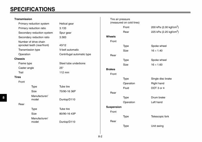
SP
8
)
200 kPa (2.00 kgf/cm2)
225 kPa (2.25 kgf/cm2)
Spoke wheel
16 × 1.40
Spoke wheel
16 × 1.60
Single disc brake
Right hand
DOT 3 or 4
Drum brake
Left hand
Telescopic fork
Unit swing
U5MXE0.book Page 2 Thursday, December 20, 2001 2:08 PM
ECIFICATIONS
8-2
Transmission
Primary reduction system Helical gear
Primary reduction ratio 3.133
Secondary reduction system Spur gear
Secondary reduction ratio 3.583
Number of drive chain sprocket teeth (rear/front) 43/12
Transmission type V-belt automatic
Operation Centrifugal automatic type
Chassis
Frame type Steel tube underbone
Caster angle 25°
Trail 112 mm
Tires
Front
Type Tube tire
Size 70/90-16 36P
Manufacturer/model Dunlop/D110
Rear
Type Tube tire
Size 80/90-16 43P
Manufacturer/model Dunlop/D110
Tire air pressure (measured on cold tires
Front
Rear
Wheels
Front
Type
Size
Rear
Type
Size
Brakes
Front
Type
Operation
Fluid
Rear
Type
Operation
Suspension
Front
Type
Rear
Type

SPECIFICATIONS
8
U5MXE0.book Page 3 Thursday, December 20, 2001 2:08 PM
8-3
Spring/shock absorbers
Front Coil spring / oil damper
Rear Coil spring / oil damper
Wheel travel
Front 80 mm
Rear 55 mm
Electrical
Ignition system DC. C.D.I.
Charging system
Type A.C. magneto
Standard output 14 V, 105 W@ 5,000 r/min
Battery
Model Local made
Voltage, capacity 12 V, 7 Ah
Headlight bulb type Incandesce bulb
Bulb voltage, wattage × quantity
Headlight 12 V, 25/25 W × 2
Tail/brake light 12 V, 5/21 W × 1
Turn signal light 12 V, 10 W × 4
Meter lighting 12 V, 1.7 W × 112 V, 3.4 W × 1
High beam indicator light 12 V, 1.7 W × 1
Turn signal indicator light 12 V, 3.4 W × 2
Fuse 10 A
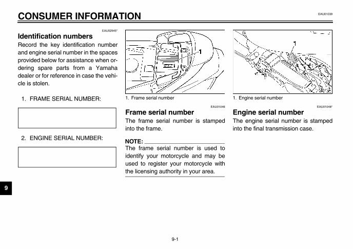
9
EAU01039
U5MXE0.book Page 1 Thursday, December 20, 2001 2:08 PM
9-CO
IdeRe
EAU01048*
gine serial number engine serial number is stamped the final transmission case.
ngine serial number
andproderdeacle
1.CA-02
2.CA-02
9-1
NSUMER INFORMATIONEAU02945*
ntification numbers cord the key identification number engine serial number in the spacesvided below for assistance when or-ing spare parts from a Yamahaler or for reference in case the vehi-is stolen.
FRAME SERIAL NUMBER:E
ENGINE SERIAL NUMBER: E
EAU01046
Frame serial number The frame serial number is stampedinto the frame.
NOTE:_
The frame serial number is used toidentify your motorcycle and may beused to register your motorcycle withthe licensing authority in your area. _
EnTheinto
1. Frame serial number 1. E

Engine start procedure
Engine oil replacement
V-belt inspection
Load limit
Before pushing start button, make sure to apply the Front or Rear Brake and that the Sidestand is retracted.
Engine oil replacement : Every 2000 km.Recommended oil : SAE20W - 50 type SF Class Motor Oil
Convenience hook : 1 kg, Helmet box: 5 kg5MX-F835Y-00
Periodic maintenance must be performed by any authorized Yamaha Dealer (Refer tothe Owner's Manual for details.)

5MX-F8199-E0
AT115PRINTED IN INDONESIA
YAMAHA MOTOR CO., LTD.
OWNER’S MANUAL