548 IEEE TRANSACTIONS ON COMPUTER-AIDED DESIGN OF INTEGRATED CIRCUITS AND SYSTEMS, VOL. 30, NO. 4, APRIL 2011 Extending the Effective Throughput of NoCs with Distributed Shared-Buffer Routers Rohit Sunkam Ramanujam, Student Member, IEEE, Vassos Soteriou, Member, IEEE, Bill Lin, Member, IEEE, and Li-Shiuan Peh, Member, IEEE Abstract —Router microarchitecture plays a central role in the performance of networks-on-chip (NoCs). Buffers are needed in routers to house incoming flits that cannot be immediately forwarded due to contention. This buffering can be done at the inputs or the outputs of a router, corresponding to an input-buffered router (IBR) or an output-buffered router (OBR). OBRs are attractive because they can sustain higher throughputs and have lower queuing delays under high loads than IBRs. However, a direct implementation of an OBR requires a router speedup equal to the number of ports, making such a design prohibitive under aggressive clocking needs and limited power budgets of most NoC applications. In this paper, a new router design based on a distributed shared-buffer (DSB) architecture is proposed that aims to practically emulate an OBR. The pro- posed architecture introduces innovations to address the unique constraints of NoCs, including efficient pipelining and novel flow control. Practical DSB configurations are also presented with reduced power overheads while exhibiting negligible performance degradation. Compared to a state-of-the-art pipelined IBR, the proposed DSB router achieves up to 19% higher throughput on synthetic traffic and reduces packet latency on average by 61% when running SPLASH-2 benchmarks with high contention. On average, the saturation throughput of DSB routers is within 7% of the theoretically ideal saturation throughput under the synthetic workloads evaluated. Index Terms—Network throughput, networks-on-chip, on-chip interconnection networks, router microarchitecture. I. Introduction N ETWORK-ON-CHIP (NoC) architectures are becom- ing the de facto fabric for both general-purpose chip multiprocessors (CMPs) and application-specific systems-on- chips (SoCs). In the design of NoCs, high throughput and low latency are both important design parameters and the router microarchitecture plays a vital role in achieving these performance goals. High throughput routers allow an NoC Manuscript received July 2, 2010; accepted November 17, 2010. Date of current version March 18, 2011. This paper was recommended by Associate Editor L. Benini. This work was supported in part by the National Science Foundation, under Grant CCF 0702341. R. S. Ramanujam and B. Lin are with the Department of Electrical and Computer Engineering, University of California, San Diego, CA 92093 USA (e-mail: [email protected]; [email protected]). V. Soteriou is with the Department of Electrical Engineering and Informa- tion Technology, Cyprus University of Technology, Limassol 3603, Cyprus (e-mail: [email protected]). L.-S. Peh is with the Department of Electrical Engineering and Computer Science, Massachusetts Institute of Technology, Cambridge, MA 02139 USA (e-mail: [email protected]). Digital Object Identifier 10.1109/TCAD.2011.2110550 to satisfy the communication needs of multi-core and many- core applications, or the higher achievable throughput can be traded off for power savings with fewer resources being used to attain a target bandwidth. Further, achieving high throughput is also critical from a delay perspective for applications with heavy communication workloads because queueing delays grow rapidly as the network approaches saturation. A router’s role lies in efficiently multiplexing packets onto the network links. Router buffering is used to house arriving flits 1 that cannot be immediately forwarded to the output links due to contention. This buffering can be done either at the inputs or the outputs of a router, corresponding to an input- buffered router (IBR) or an output-buffered router (OBR). OBRs are attractive for NoCs because they can sustain higher throughputs and have lower queueing delays than IBRs under high loads. However, a direct implementation of an OBR requires each router to operate at a speedup of P , where P is the number of router ports. This can either be realized with the router being clocked at P times the link clock frequency or the router having P times more internal buffer and crossbar ports. Both of these approaches are prohibitive given the aggressive design goals of most NoC applications, such as high-performance CMPs. This is a key reason behind the broad adoption of IBR microarchitectures as the preferred design choice and the extensive prior effort in the computer architec- ture community on aggressively pipelined IBR designs. In this paper, we propose a new router microarchitecture that aims to emulate an OBR without the need for any router speedup. It is based on a distributed shared-buffer (DSB) router architecture that has been successfully used in high- performance Internet packet routers [10], [24]. Rather than buffering data at the output ports, a DSB router uses two crossbar stages with buffering sandwiched in between. These buffers are referred to as middle memories (MMs). To emulate the first-come first-served (FCFS) order of an OBR, incoming packets are timestamped with the same departure times as they would depart in an OBR. Packets are then assigned to one of the MM buffers with two constraints. First, packets that are arriving at the same time must be assigned to different MMs. Second, an incoming packet cannot be assigned to a MM that already holds a packet with the same departure time. 2 It has been shown in [10] and [24] that a DSB 1 A flit is a fixed-size portion of a packetized message. 2 This is necessary to avoid switch contention. 0278-0070/$26.00 c 2011 IEEE
Transcript
548 IEEE TRANSACTIONS ON COMPUTER-AIDED DESIGN OF INTEGRATED CIRCUITS AND SYSTEMS, VOL. 30, NO. 4, APRIL 2011
Extending the Effective Throughput of NoCs withDistributed Shared-Buffer Routers
Abstract—Router microarchitecture plays a central role in theperformance of networks-on-chip (NoCs). Buffers are neededin routers to house incoming flits that cannot be immediatelyforwarded due to contention. This buffering can be done atthe inputs or the outputs of a router, corresponding to aninput-buffered router (IBR) or an output-buffered router (OBR).OBRs are attractive because they can sustain higher throughputsand have lower queuing delays under high loads than IBRs.However, a direct implementation of an OBR requires a routerspeedup equal to the number of ports, making such a designprohibitive under aggressive clocking needs and limited powerbudgets of most NoC applications. In this paper, a new routerdesign based on a distributed shared-buffer (DSB) architectureis proposed that aims to practically emulate an OBR. The pro-posed architecture introduces innovations to address the uniqueconstraints of NoCs, including efficient pipelining and novel flowcontrol. Practical DSB configurations are also presented withreduced power overheads while exhibiting negligible performancedegradation. Compared to a state-of-the-art pipelined IBR, theproposed DSB router achieves up to 19% higher throughputon synthetic traffic and reduces packet latency on average by61% when running SPLASH-2 benchmarks with high contention.On average, the saturation throughput of DSB routers is within7% of the theoretically ideal saturation throughput under thesynthetic workloads evaluated.
Index Terms—Network throughput, networks-on-chip, on-chipinterconnection networks, router microarchitecture.
I. Introduction
NETWORK-ON-CHIP (NoC) architectures are becom-ing the de facto fabric for both general-purpose chip
multiprocessors (CMPs) and application-specific systems-on-chips (SoCs). In the design of NoCs, high throughput andlow latency are both important design parameters and therouter microarchitecture plays a vital role in achieving theseperformance goals. High throughput routers allow an NoC
Manuscript received July 2, 2010; accepted November 17, 2010. Date ofcurrent version March 18, 2011. This paper was recommended by AssociateEditor L. Benini. This work was supported in part by the National ScienceFoundation, under Grant CCF 0702341.
R. S. Ramanujam and B. Lin are with the Department of Electrical andComputer Engineering, University of California, San Diego, CA 92093 USA(e-mail: [email protected]; [email protected]).
V. Soteriou is with the Department of Electrical Engineering and Informa-tion Technology, Cyprus University of Technology, Limassol 3603, Cyprus(e-mail: [email protected]).
L.-S. Peh is with the Department of Electrical Engineering and ComputerScience, Massachusetts Institute of Technology, Cambridge, MA 02139 USA(e-mail: [email protected]).
Digital Object Identifier 10.1109/TCAD.2011.2110550
to satisfy the communication needs of multi-core and many-core applications, or the higher achievable throughput can betraded off for power savings with fewer resources being usedto attain a target bandwidth. Further, achieving high throughputis also critical from a delay perspective for applications withheavy communication workloads because queueing delaysgrow rapidly as the network approaches saturation.
A router’s role lies in efficiently multiplexing packets ontothe network links. Router buffering is used to house arrivingflits1 that cannot be immediately forwarded to the output linksdue to contention. This buffering can be done either at theinputs or the outputs of a router, corresponding to an input-buffered router (IBR) or an output-buffered router (OBR).OBRs are attractive for NoCs because they can sustain higherthroughputs and have lower queueing delays than IBRs underhigh loads. However, a direct implementation of an OBRrequires each router to operate at a speedup of P , where P isthe number of router ports. This can either be realized withthe router being clocked at P times the link clock frequencyor the router having P times more internal buffer and crossbarports. Both of these approaches are prohibitive given theaggressive design goals of most NoC applications, such ashigh-performance CMPs. This is a key reason behind the broadadoption of IBR microarchitectures as the preferred designchoice and the extensive prior effort in the computer architec-ture community on aggressively pipelined IBR designs.
In this paper, we propose a new router microarchitecturethat aims to emulate an OBR without the need for any routerspeedup. It is based on a distributed shared-buffer (DSB)router architecture that has been successfully used in high-performance Internet packet routers [10], [24]. Rather thanbuffering data at the output ports, a DSB router uses twocrossbar stages with buffering sandwiched in between. Thesebuffers are referred to as middle memories (MMs). To emulatethe first-come first-served (FCFS) order of an OBR, incomingpackets are timestamped with the same departure times as theywould depart in an OBR. Packets are then assigned to oneof the MM buffers with two constraints. First, packets thatare arriving at the same time must be assigned to differentMMs. Second, an incoming packet cannot be assigned to aMM that already holds a packet with the same departuretime.2 It has been shown in [10] and [24] that a DSB
1A flit is a fixed-size portion of a packetized message.2This is necessary to avoid switch contention.
RAMANUJAM et al.: EXTENDING THE EFFECTIVE THROUGHPUT OF NOCS WITH DISTRIBUTED SHARED-BUFFER ROUTERS 549
router can emulate a FCFS OBR if unlimited buffering isavailable.
However, just as the design objectives and constraints foran on-chip IBR are quite different from those for an Internetpacket router, the architecture tradeoffs and design constraintsfor an on-chip DSB router are also quite different. First,limited power and area budgets restrict a practical routermicroarchitecture implementation to contain small amountsof buffering. It is, therefore, imperative to explore power-efficient and area-efficient DSB configurations suitable for on-chip design. Next, a flow-control protocol which can workwith few buffers is necessary since NoC applications andprotocols, such as cache coherency, cannot tolerate droppingof packets. A suitable flow-control mechanism is also neededto support a wide range of delay-sensitive applications withultra-low latency requirements. This can be achieved with flit-level flow control that allows allocation of network resources atthe granularity of flits. This is different from Internet routerswhich typically employ store-and-forward packet-level flowcontrol. Finally, another key difference is the need for on-chip routers to operate at aggressive clock frequencies. Thiscan be achieved with efficient router pipelining where circuitdelay and complexity are balanced across all router pipelinestages. Our proposed router microarchitecture tackles all thesechallenges with appropriate solutions and new designs.
Our evaluation shows that the proposed on-chip DSB routerachieves up to 19% higher saturation throughput in comparisonto a state-of-the-art pipelined IBR and up to 94% of theideal saturation throughput for the synthetic traffic workloadsevaluated. On the set of SPLASH-2 benchmarks [26] whichexhibit high contention and demand high bandwidth, ourresults further show that the proposed DSB router reducespacket latency by 61% on average when compared with IBRs.
The remainder of this paper is organized as follows. Sec-tion II provides background information on throughput analy-sis and on existing router architectures. Section III describesour proposed DSB router microarchitecture for NoCs. Next,Section IV provides extensive throughput and latency eval-uations of our proposed DSB architecture using a detailedcycle-accurate simulator on a range of synthetic network tracesand traffic traces gathered from real system simulations, whileSection V evaluates the power and area overhead of DSBrouters. Section VI reviews related work. Finally, Section VIIconcludes this paper.
II. Background
In this section, we first provide a brief background onthroughput analysis. We then present a short description ofOBR and IBR microarchitectures, focusing on their deficien-cies in practically attaining ideal throughput, before discussingdistributed-shared-buffer Internet routers and how they mimicoutput buffering [10], [24].
A. Throughput Analysis
Here, we provide a brief overview of the analysis techniquesused to evaluate ideal network throughput. In particular, weelaborate on the concepts of network capacity, channel load,
TABLE I
Traffic Patterns and Their Corresponding Ideal Saturation
Throughput Under DOR-XY Routing
SaturationTraffic Description ThroughputUniform Destination chosen at random, uniformly 1.0
Tornado (x, y) to ((x +⌈
k2
⌉− 1)%k, (y +
⌈k2
⌉− 1)%k) 0.66
Complement (x, y) to (k − x − 1, k − y − 1) 0.5
and saturation throughput. These concepts are intended tocapture what could be ideally achieved for a routing algorithmR on a given traffic pattern �. To decouple the effects of therouter microarchitecture, including buffer sizing and the flowcontrol mechanism being used, ideal throughput analysis isbased on channel load analysis. We first review the conceptof network capacity.
1) Network Capacity: Network capacity is defined by themaximum channel load, γ∗, that a channel at the bisectionof the network needs to sustain under uniformly distributedtraffic. As shown in [5], for any k × k mesh
γ∗ =
⎧⎪⎨
⎪⎩
k
4, for even k
k2 − 1
4k, for odd k.
The network capacity, N , in flits per node per cycle is thendefined as the inverse of γ∗ as follows:
N =1
γ∗ =
⎧⎪⎨
⎪⎩
4
k, for even k
4k
k2 − 1, for odd k.
For example, for a k × k mesh, with k = 8, N = 4/8 =0.5 flits/node/cycle. Next, we review the concept of saturationthroughput.
2) Saturation Throughput: For a routing algorithm R and agiven traffic pattern �, the expected channel load on a channelc is denoted as γc(R, �). The normalized worst-case channelload, γwc(R, �), is then defined as the expected number offlits crossing the most heavily loaded channel, normalized toγ∗, as follows:
γwc(R, �) =maxc∈C γc(R, �)
γ∗
where C is the set of all channels in the network.Given this definition of normalized worst-case channel load,
the saturation throughput corresponds to the average numberof flits that can be injected per cycle by all the nodes in thenetwork so as to saturate the most heavily loaded channel toits unit capacity. This is given as follows:
�(R, �) =1
γwc(R, �).
Saturation throughput is defined specifically for a given routingalgorithm R and traffic pattern �. Table I shows a few com-monly used traffic patterns and their corresponding saturationthroughput under dimension-ordered XY routing (DOR-XY).Note that 100% capacity cannot always be achieved withDOR-XY routing even under an ideal router design, defined
550 IEEE TRANSACTIONS ON COMPUTER-AIDED DESIGN OF INTEGRATED CIRCUITS AND SYSTEMS, VOL. 30, NO. 4, APRIL 2011
as the one that can handle injection loads up to the saturationthroughput. For example, for an adversarial traffic patternlike bit-complement traffic, it is well-known that DOR-XYrouting saturates at 50% of network capacity. To decouplethe effects of the routing algorithm on network performance,we assume DOR-XY routing throughout the remainder ofthis paper. The goal of our router design is to reach theideal router performance and thus approach the achievablesaturation throughput.
B. OBRs
Fact 1: An OBR with unlimited buffering can achieve thetheoretical saturation throughput.
Fact 2: OBRs with unlimited buffering have predictableand bounded packet delays when the network is below sat-uration.
Emulating the FCFS behavior of OBR architectures isimportant for exploiting their attractive high-throughput andlow-latency properties. Throughput guarantees offered by alloblivious routing algorithms [5], which are often used inNoCs because of their simplicity, assume ideal output-bufferedrouting with infinite buffers when performing throughput anal-ysis. When the network topology and the traffic matrix areboth known, the saturation throughput for oblivious routingalgorithms can be computed based on worst-case channelload analysis (as described in Section II-A). Even when noinformation about the spatial characteristics of the trafficis available, which is often the case, worst-case throughputguarantees of oblivious routing functions can be providedby solving bipartite maximum-weight matching problems foreach channel [29]. These throughput guarantees do not hold ifthe routers used do not emulate an OBR. Generally, usingIBRs, the worst-case saturation throughput of an obliviousrouting algorithm can be quite far off from the value pre-dicted by worst-case throughput analysis (Fig. 3). So one keyadvantage of OBR emulation is to provide and retain suchguarantees with the limited hardware resources available inon-chip routers.
OBRs also have lower and more predictable queueing delaysthan IBRs because of their FCFS servicing scheme. Flits arenot delayed in OBRs unless the delay is unavoidable dueto multiple flits arriving at the same time at different inputports destined for the same output port. On the contrary, theswitch arbitration (SA) schemes used in IBRs for multiplexingpackets onto links are suboptimal and result in unpredictablepacket delays. The predictability of packet delays is an impor-tant concern for delay-sensitive NoC applications and OBRemulation is a step forward in this direction.
Fig. 1 depicts the OBR architecture. In this architecture, in-coming flits are directly written into the output buffers througha concentrator. Since up to P flits may arrive together for aparticular output in the same cycle, a direct implementation ofan OBR would require a router speedup of P , where P is thenumber of router ports (i.e., P = 5 in Fig. 1). Router speedupcan be realized in two ways. First, by clocking the routerat P times the link frequency, which is highly impracticalwith today’s aggressive clock rates. Even if realizable, thiswill lead to exorbitant power consumption. Second, it can
Fig. 1. OBR architecture model.
Fig. 2. (a) Typical IBR microarchitecture with VC flow control and twoVCs, and (b) its three-stage pipeline: 1) route computation (RC) + virtual-channel allocation (VA) + switch arbitration (SA); 2) switch traversal (ST);and 3) link traversal (LT).
be realized with higher internal port counts at the buffersand the crossbar; each output buffer needs P write ports,with input ports connected to the output buffers through aP × P2 crossbar. This scenario leads to huge complementarymetal-oxide-semiconductor area penalties. High power andarea requirements for OBR implementation are the key reasonsbehind the broad adoption of IBR microarchitectures as theprincipal design choice and the extensive prior effort in thecomputer architecture community on aggressively pipelinedIBR designs (see Section VI), despite the very attractive prop-erty that an OBR can theoretically reach the ideal saturationthroughput. Subsequently, in Section II-D, we review a DSBrouter architecture that emulates an OBR, inheriting its eleganttheoretical properties, without the need for P times routerspeedup. We first review the IBR microarchitecture that iswidely used in on-chip interconnection networks.
C. IBR Microarchitecture
Fig. 2(a) sketches a typical IBR microarchitecture [5] that isgoverned by virtual-channel (VC) flow control [4]. We adoptthis as the baseline IBR for our evaluations. The router has P
ports, where P depends on the dimension of the topology. In a2-D mesh, P = 5 as it includes the four NSEW ports as well asthe injection/ejection port from/to the processor core. At eachinput port, buffers are organized as separate first-in first-outqueues, one for each VC. Flits entering the router are placedin one of these queues depending on their VC ID. Queues of aninput port typically share a single crossbar input port, as shown
RAMANUJAM et al.: EXTENDING THE EFFECTIVE THROUGHPUT OF NOCS WITH DISTRIBUTED SHARED-BUFFER ROUTERS 551
Fig. 3. Latency-throughput curve of an IBR with unlimited buffering, VCsand perfect allocation (Ford–Fulkerson matching algorithm [7]).
in Fig. 2(a), with crossbar output ports directly connected tooutput links that interconnect the current (upstream) routerwith its neighboring (downstream) router.
Fig. 2(b) shows the corresponding IBR router pipeline. Therouter uses look-ahead routing and speculative switch alloca-tion (SA) resulting in a short three-stage router pipeline. Routecomputation (RC) determines the output port based on thepacket destination and is done one hop in advance. SpeculativeSA is done in parallel with virtual-channel allocation (VA) andpriority is given to nonspeculative switch requests to ensurethat performance is not hurt by speculation. Once SA and VAare completed, flits traverse the crossbar (ST) before finallytraversing the output link [link traversal (LT)] toward thedownstream router. Head flits proceed through all the stageswhile the body and tail flits skip the RC and VA stages andinherit the VC allocated to the head flit. The tail flit releasesthe reserved VC after departing the upstream router.
To attain high throughput, an IBR relies on several keymicroarchitectural components to effectively multiplex flitsonto the output links. First, additional buffering allows agreater number of flits to be housed at a router duringhigh contention. This increases the number of competing flitcandidates to eventually traverse a link toward a downstreamrouter, while also alleviating congestion at upstream routers.Second, a higher number of VCs allows a greater number ofindividual packet flows to be accommodated, increasing bufferutilization and ultimately link utilization. Finally, the VC andswitch allocators need to have good matching capability, i.e.,they should ensure that VCs and crossbar switch ports nevergo idle when there are flits waiting for them.
To explore the throughput limits of an IBR, we simulated an8×8 mesh network of IBRs with a pipelined microarchitectureas described above, but with unlimited buffering and VCs,and perfect matching (Ford–Fulkerson allocation [7]). Four-flit packets were sent uniformly to random destinations androuted using DOR-XY routing. Section IV describes thedetailed simulation methodology. Fig. 3 compares the latency-throughput curve of the ideal IBR with the curve of anOBR having the same number of pipeline stages. Despiteunlimited buffering, VCs and perfect matching, all of whichare impractical as they command impossibly huge area, power,and delay overheads, the IBR obtained only about 81% of idealsaturation throughput. This is because of the bottlenecks that
Fig. 4. DSB router architecture model.
exist along the datapath of an IBR; buffers are partitioned perinput port, and all VC queues at an input port share a singleport into the crossbar. So when multiple packet flows at aninput port wish to depart through different output ports, theyneed to queue up and leave the input buffer one at a time.OBRs precisely tackle this deficiency and can achieve near-ideal saturation throughput, as Fig. 3 shows.
D. DSB Routers
DSB routers have been successfully used in high-performance Internet packet routers [10], [24] to emulateOBRs without any internal router speedup. Rather than buffer-ing data directly at the output ports, a DSB router uses twocrossbar stages with buffering sandwiched in between. Fig. 4depicts the DSB microarchitecture used in Internet routers.The input ports are connected via a P × N crossbar to N
MMs. These N MMs are then connected to the output portsvia a second N × P crossbar. At every cycle, one packet canbe read from and written to each MM. It should be noted herethat when contention occurs in Internet routers, packets can bedropped. This scenario is not allowed in our proposed on-chipDSB architecture (see Section III).
To emulate the FCFS packet servicing in OBRs, a DSBrouter has to satisfy two conditions: 1) a packet is dropped bythe DSB router if and only if it will also be dropped by anOBR, and 2) if a packet is not dropped, then the packet mustdepart the DSB router at the same cycle as the cycle in which itwould have departed an OBR. To achieve this emulation, eachpacket arriving at a DSB router is timestamped with the cyclein which it would have departed from an OBR (i.e., in FCFSorder). When a packet arrives, a scheduler chooses a MMto which to write this incoming packet and to appropriatelyconfigure the corresponding first crossbar (XB1). Also, at eachcycle, packets whose timestamp is equal to the current cycletime are read from the MMs and transferred to the outputsthrough the second crossbar (XB2).
In [10] and [24], it was shown that a MM assignment canalways be found and a DSB router can exactly emulate anOBR if the following condition is satisfied.
Fact 3: A DSB router with N ≥ (2P − 1) MMs andunlimited buffering in each MM can exactly emulate a FCFSOBR with unlimited buffering.At least (2P −1) MMs are needed to ensure that two types ofconflicts can always be resolved. The first type of conflict is anarrival conflict. A packet has an arrival conflict with all packetsthat arrive simultaneously at other input ports since packetsarriving at the same time cannot be written to the same MM.With P input ports, the maximum number of arrival conflicts
552 IEEE TRANSACTIONS ON COMPUTER-AIDED DESIGN OF INTEGRATED CIRCUITS AND SYSTEMS, VOL. 30, NO. 4, APRIL 2011
a packet can have is (P − 1). The second type of conflict isa departure conflict. A packet has a departure conflict withall other packets that have the same timestamp and need todepart simultaneously through different output ports. With P
output ports, a packet can have departure conflicts with at most(P − 1) other packets. Therefore, by the pigeonhole principle,N ≥ (2P − 1) MMs are necessary and sufficient to find aconflict-free MM assignment for all incoming packets.
III. Proposed DSB Router for NoCs
A. Key Architectural ContributionsThe proposed DSB NoC router architecture addresses the
bottlenecks that exist in the data path of IBRs which lead tolower than theoretical ideal throughput. At the same time, ittackles the inherent speedup limitations and area penalties ofOBRs while harnessing their increased throughput capabilities.The MMs decouple input VC queueing from output channelbandwidth, as any flit can acquire any MM provided that thereare no timing conflicts with other flits already stored in thesame MM. Essentially, MMs provide path diversity betweenthe input and output ports within a router. Although based onthe DSB architecture used in Internet routers, the proposedNoC router architecture faces a number of challenges specificto the on-chip domain.
First and foremost, NoC applications such as cache co-herence protocols cannot tolerate dropping of packets unlikein Internet protocols. As a result, the DSB architecture usedin Internet routers cannot be directly applied to the on-chip domain. To guarantee packet delivery, a flow controlmechanism needs to be in place. The proposed DSB routeruses credit-based flit-level flow control. To implement credit-based flow control, we introduce input buffers with VCs anddistribute the available router buffers between the input portsand the MMs. Flow control is applied on a flit-by-flit basis,advancing each flit from an input queue toward any time-compatible MM and ultimately to the output link. Flits aretimestamped and placed into a compatible MM only when thenext-hop router has buffers available at its corresponding inputport. Further, since the MM buffering is limited due to powerand area constraints, flits are held back in the input bufferswhen they fail to find a compatible MM.
Next, since power is of utmost importance in the NoCdomain, the power-performance tradeoff of different DSBconfigurations needs to be explored. Although, theoretically,2P − 1 MMs are needed in a P-ported router to avoid allpossible arrival and departure conflicts, having a large numberof MMs increases power and area overheads by increasingthe crossbar size. Therefore, we evaluate DSB configurationswith fewer than 2P − 1 MMs and estimate the impact of thereduced number of MMs on performance.
Finally, on-chip routers need to operate at aggressive clockfrequencies, pointing to the need for careful design of routerpipelines with low complexity logic at each stage. Our designassumes a delay and complexity-balanced five-stage pipeline.The proposed DSB architecture can achieve much higherperformance than VC IBRs with comparable buffering whileadding reasonable power and area overheads in managingMMs and assigning timestamps to flits.
Fig. 5. (a) DSB router microarchitecture with N MMs and (b) its five-stagepipeline: 1) route computation (RC) + timestamping (TS); 2) conflict resolu-tion (CR) and virtual-channel allocation (VA); 3) first crossbar traversal (XB1)+ middle memory write (MM WR); 4) middle memory read (MM RD) andsecond crossbar traversal (XB2); and 5) link traversal (LT).
B. DSB Microarchitecture and Pipeline
Fig. 5 shows the router microarchitecture of the proposedDSB router and its corresponding five-stage pipeline. Incom-ing flits are first buffered in the input buffers which aresegmented into several atomic VCs. The RC stage employs alook-ahead routing scheme like the baseline IBR architecture,where the output port of a packet is computed based onthe destination coordinates, one hop in advance. This is doneonly for the head flit of a packet. The remaining pipelinestages of a DSB router are substantially different from thoseof IBRs. Instead of arbitrating for free VCs (buffering) andpassage through the crossbar switch (link), flits in a DSBrouter compete for two resources: MM buffers (buffering) anda unique time at which to depart from the MM to the outputport (link).
The timestamping (TS) stage deals with the timestampresource allocation. A timestamp refers to the future cycle atwhich a flit will be read from a MM, through the secondcrossbar, XB2, onto the output port. TS is carried out inconjunction with lookahead routing. A flit (head, body, or tail)enters the TS stage and issues a request to the timestamper ifit is at the head of a VC or if the flit ahead of it in the sameVC has moved to the second stage of the pipeline. A flit canalso re-enter the TS stage if it fails to find either a conflict-free MM or a free VC at the input of the next-hop router, aswill be explained later. If multiple VCs from the same inputport send simultaneous requests to the timestamper, it picks awinning VC and assigns the earliest possible departure timefor the output port requested by the flit in the selected VC.Let us assume that the output port requested is p. In order tofind the earliest possible departure time through port p, thetimestamper first computes the time the flit would leave theMM assuming there are no flits already stored in the MMsthat need to depart through port p. Let us denote this time asT [p] as follows:
T [p] = Current Time + 3
RAMANUJAM et al.: EXTENDING THE EFFECTIVE THROUGHPUT OF NOCS WITH DISTRIBUTED SHARED-BUFFER ROUTERS 553
Fig. 6. Arrival CR illustration for flits under a simplified DSB routerarchitecture with two input ports (no VCs), two output ports, and two MMs,MM[0] and MM[1], each with a three-flit capacity. FA and FB need to departthrough the same output port. They are timestamped at the same current cyclei. FA is assigned a timestamp of i + 3 while FB is assigned a timestamp ofi + 4, assuming input 1 has a higher priority than input 2 and there are noflits already stored in the MM buffers. Although FA and FB are in differentinput ports and have different departure times, they cannot be simultaneouslywritten into the same MM, as each memory has a single write port. SoFA and FB are assigned to MM[0] and MM[1], respectively. (a) Time = i.(b) Time = i + 2.
since two pipeline stages, namely, CR + VA (conflict resolution+ VC allocation) and XB1 + MM WR (crossbar 1 and MMwrite) lie between the TS and MM RD + XB2 (MM read andcrossbar 2) stages in the DSB pipeline (see Fig. 5). Next, weconsider the case when there are flits in the MMs destined foroutput port p. To handle this case, the timestamper remembersthe value of the last timestamp assigned for each output portup to until the previous cycle. The last assigned timestampfor output port p is denoted as LAT [p]. As timestamps areassigned in a strictly increasing order, the assigned times-tamp for output port p in the current cycle must be greaterthan LAT [p]. In other words, a flit that is currently beingtimestamped can depart the MM through output port p onlyafter all flits that are destined for the same output port andwere timestamped at an earlier cycle, depart the MM. Thisemulates the FCFS servicing scheme of OBRs. Hence, theearliest timestamp that can be assigned to a flit for output portp is given as follows:
Timestamp = max(LAT [p] + 1, T [p]). (1)
If flits at more than one input port request a timestampfor output port p in the same cycle, the timestamper servesthe inputs in an order of decreasing priority (either fixed orrotating). The timestamp of a flit at the highest priority inputis computed as above and the remaining flits at other inputsare assigned sequentially increasing timestamps in the orderof decreasing priority.
CR and VA comprise the second pipeline stage of theDSB router. The CR and VA operations are carried out inparallel. The task of the CR stage is to find a conflict-free MMassignment for flits that were assigned timestamps in the TS
Fig. 7. Departure CR illustration for flits under a simplified DSB routerarchitecture with two input ports (no VCs), two output ports, and two MMs,MM[0] and MM[1], each with a three-flit capacity. Flit FA enters the TS stageat current time i for output port 1 and is assigned a timestamp of i + 3 sincethere are no flits in any MMs destined for output port 1. When it enters theCR stage in the next cycle, there are two flits already stored in MM[0] havingtimestamps i + 2 and i + 3 destined for output port 2. Although MM[0] has anempty slot to store an additional flit, FA cannot be assigned to MM[0] sinceit has a conflicting departure time with a flit already stored in MM[0] whichhas only one read port. So, flit FA has to be assigned to MM[1]. (a) Time =i. (b) Time = i + 1. (c) Time = i + 2.
stage. As mentioned earlier, there are two kinds of conflicts inshared-buffer routers: arrival conflicts and departure conflicts.Arrival conflicts are handled by assigning a different MM toevery input port with timestamped flits. Departure conflictsare avoided by ensuring that the flits stored in the sameMM have unique timestamps. Figs. 6 and 7 demonstrate howarrival and departure conflicts are resolved in a simplified DSBarchitecture. These restrictions are enforced due to the fact thatMMs are uni-ported3 and only one flit can be written into (viaXB1) and read from (via XB2) a MM in a given cycle. Theimplementation details of the TS and CR stages are explainedin the next section.
The VC allocator arbitrates for free VCs at the input portof the next-hop router in parallel with CR. VA is done onlyfor the head flit of a packet. The VC allocator maintains twolists of VCs: a reserved VC pool and a free VC pool. VA isdone by picking the next free output VC from the free VClist of the given output port, similar to the technique usedin [15]. Additionally, when output VCs are freed, their VCnumber is moved from the reserved VC list to the end of thefree VC list. If a free VC exists and the flit is granted a MM,it subsequently proceeds to the third pipeline stage, where it
3Single-ported memories are power and area-efficient.
554 IEEE TRANSACTIONS ON COMPUTER-AIDED DESIGN OF INTEGRATED CIRCUITS AND SYSTEMS, VOL. 30, NO. 4, APRIL 2011
traverses the first crossbar (XB1) and is written to its assignedMM (MEM WR). If no free VC exists (all VCs belong to thereserved VC list), or if CR fails to find a conflict-free MM,the flit has to be re-assigned a new timestamp and it thereforere-enters the TS stage.
When the timestamp of a flit matches the current routertime, the flit is read from the MM, MM RD, and passesthrough the second crossbar, XB2, in the fourth pipeline stage.We assume that the output port information is added to everyflit and stored along with it in the MM. Finally, in the LTstage, flits traverse the output links to reach the downstreamrouter.
C. Practical Implementation
In this section, we describe the implementation details ofthe TS and CR stages, which are unique to the proposedDSB architecture. It must be noted here that the proposedimplementation is only one among a range of possible designimplementation choices that span a spectrum of area/delaytradeoffs. We specifically focus on the implementation of afive-ported 2-D mesh router. However, our design can beextended to higher or lower radix routers.
The high-level block diagrams of the logic used in the TSstage are shown in Fig. 8(a)–(c). The five input ports arelabeled from i0 to i4. First, as shown in Fig. 8(a), whenmultiple VCs from the same input port send simultaneousrequests to the timestamper, a winning VC is selected usinga matrix arbiter. In addition to the TS requests, the arbiteralso takes as input the size of the free VC lists for the outputports requested by each of the flits in the TS stage and givespriority to body and tail flits that have already acquired a VCover head flits, if they are likely to fail in the VA stage. Thisavoids wasted cycles resulting from re-TS of flits.
After choosing a winning VC at each input port, the outputports requested by the flits in the selected VCs, OPi, areused to generate timestamp offsets for each of these flits,as shown in Fig. 8(b). Timestamp offsets are required toassign sequentially increasing timestamps to flits based oninput priority, when flits from more than one input portsimultaneously request a timestamp for the same output port,as discussed in Section III-B. Internally, the offset generatorblock comprises of separate sub-blocks, one for each outputport. The offsets are generated on a per output port basis andthe offset value for a flit is equal to the number of higherpriority flits requesting a timestamp for the same output portin a given cycle. The offset generation sub-block for an outputport is a simple combinational function of the requests receivedfrom the input ports (OPi) and the input priorities. The finaltimestamp assigned to a flit at input i is the sum of thetimestamp assigned to the highest priority flit requesting thesame output port as the current flit [given by (1)] and the com-puted offset as follows:
TSi = max(LAT [OPi] + 1, current time + 3) + offseti. (2)
In the DSB architecture, flits are stored in MMs only afterthey have reserved buffering at the next-hop router. Let thetotal buffering at each input port be B flits. If the current time
Fig. 8. Block diagrams of the TS stage. (a) Arbitration. (b) Offset generation.(c) Timestamp computation. (d) Compute timestamp block.
Fig. 9. Block diagram of the CR stage.
is denoted by curr time, we restrict the maximum timestampassigned for an output port to curr time + B − 1. This isbecause, assigning a timestamp equal to curr time+B meansthat there are B flits before the current flit (with timestampscurr time to curr time+B−1) that have been timestampedfor the same output port and have not yet departed the router.If all timestamped flits succeed in acquiring an output VC anda conflict-free MM, these B flits would reserve all availablebuffering at the input of the next-hop router and any flit witha timestamp greater than curr time + B − 1 would fail toreserve an output VC. Hence, assigning timestamps greaterthan curr time + B − 1 is not necessary. This fact is used to
RAMANUJAM et al.: EXTENDING THE EFFECTIVE THROUGHPUT OF NOCS WITH DISTRIBUTED SHARED-BUFFER ROUTERS 555
simplify the hardware for detecting departure conflicts. Fromthis discussion, at most B unique timestamps are assigned foran output port, which can be represented using �log2 B� bits.We ensure that each MM has exactly B flits of buffering sothat a flit with timestamp T is always stored at the T th locationwithin the MM. In this way, a flit with timestamp T can onlyhave departure conflicts with flits stored at the T th location ofany one of the N MMs.
With timestamps represented using �log2 B� bits, the times-tamp assignment has to be carried out using modulo-Barithmetic. Under this scheme, the current time rolls overevery B clock cycles, implemented using a mod-B counter.The assigned timestamps can take B unique values and alsoroll over beyond B. Hence, if curr time%B has a valuet, flits stored in the MMs can have B unique timestampsbetween t and (t − 1)%B, representing times from curr time
to curr time + B − 1. The last assigned timestamp for anoutput port can fall behind curr time when the output portis not used for a while. If the last assigned timestamp foroutput port OP falls behind curr time%B (i.e. LAT [OP] =curr time%B), it is advanced along with the current time toensure that the last assigned timestamp is always either equalto or ahead of curr time%B. This prevents old values ofLAT [OP] from appearing as future timestamps after rollover.Fig. 8(d) presents the logic diagram for the timestamp compu-tation block shown in Fig. 8(c). When assigning a timestampfor output port OPi, (LAT [OPi] + 1)%B is simultaneouslycompared to (curr time + 1)%B and (curr time + 2)%B,and the results are ORed together. A logic 1 at the outputof the OR gate signifies that (LAT [OPi] + 1)%B is behind(curr time + 3)%B and vice versa. The greater of the twotimes is chosen and the corresponding flit offset is added toobtain the final timestamp according to (2). If the timestampcomputed using (2) is greater than B, it is rolled over bysubtracting B from the result, as shown.
In the last block of Fig. 8(c), the timestamps are shuffledaccording to input priority, which is assumed to be a rotatingpriority over all inputs. In this respect, PTS0 is the timestampof the input with priority 0, PTS1 is the timestamp of inputwith priority 1, and so on. This helps with the priority-basedMM assignment during the CR stage. If an input does not holda flit that needs to be timestamped, an invalid timestamp valueis stored instead.
The task of the CR stage is to detect arrival and departureconflicts. To keep track of the occupancy of the MM buffers,we use an auxiliary data structure called the MM reservationtable (MMRT). For N MMs, with B flits of buffering per MM,the MMRT is an array of B registers, each N bits wide. Theregisters are indexed from 0 to B − 1. If bit MMRT [i][j] isset, it implies that memory bank j holds a flit with timestampi and vice versa.
Departure conflicts are resolved using the MMRT. For eachtimestamp that needs to be assigned a MM (PTS0. . . PTS4),the MMRT register indexed by the timestamp represents theMM compatibility bitmap for the timestamp. In Fig. 9, thebits C[i][0] to C[i][N − 1] represent the individual bits ofthe N-bit register, MMRT [PTSi]. If bit C[i][j] is 1, it meansthat MM j already has a flit with timestamp PTSi and hence,
has a departure conflict with any flit with this timestamp. Onthe contrary, if C[i][j] is 0, the flit with timestamp PTSi iscompatible with MM j. If an input does not have a flit thatneeds to be timestamped, the compatibility bits for all MMsare set to 1 (meaning incompatible).
Next, arrival conflicts are resolved in the MM assignmentstage. The MMs are assigned fixed priorities with memoryN − 1 given the highest priority and memory 0 the lowestpriority. In the MM assignment stage, the inputs are grantedthe highest priority compatible MM in the order of decreasinginput priority while ensuring that more than one input is notgranted the same MM. Bit G[i][j] denotes the grant bit andit is set to 1 if the input with priority i has been grantedMM j. This memory assignment scheme was specificallydesigned to have low MM miss rates when the number ofMMs is fewer than 2P − 1 (P being the number of ports)for five-ported mesh routers. Having less than 2P − 1 MMsis necessary to reduce the power and area of DSB routers asshown in Section V. When the number of MMs is at least2P − 1, memory assignment schemes with less delay can beimplemented as it is much easier to find conflict-free MMs.
The above logic distribution between the TS and CR stageswas architected to even-out the fan-out-of-4 (FO4) delaysacross the four stages (excluding LT) of the DSB pipeline.The FO4 calculations were carried out using the method oflogical effort [28], and was applied to each logic block. Fora five-ported DSB router with five VCs per input port, fourflits per VC (B = 20 flits) and five MMs with 20 flits perMM, the critical path delays of the TS and CR pipeline stageswere estimated at 19 FO4s and 18 FO4s, respectively. Adelay of less than 20 FO4 for each stage in the proposedarchitecture enables an aggressively clocked high-performanceimplementation. In particular, assuming a FO4 delay of 15 psfor Intel’s 65 nm process technology, our proposed design canbe clocked at a frequency of more than 3 GHz.
IV. Throughput and Latency Evaluation
A. Simulation Setup
To evaluate the effectiveness of our proposed DSB routeragainst a baseline IBR architecture with VC flow control,we implemented two corresponding cycle-accurate flit-levelsimulators. The baseline IBR simulator has a three-stagepipeline as described in Section II-C. The DSB simulator mod-els the five-stage router pipeline described in Section III-B.Both simulators support k-ary 2-mesh topologies with theircorresponding five-ported routers. DOR-XY routing is usedfor all our simulations where packets are first routed in theX-dimension followed by the Y -dimension. We use DOR-XYbecause our main focus is on highlighting the improvement inperformance due to the DSB router architecture, rather thanthe routing algorithm.
We present results for both synthetic and real traffic traces.The three synthetic traffic traces used are uniform, com-plement, and tornado traffic, shown in Table I. Thesethree traces represent a mixture of benign and adversarialtraffic patterns. The ideal saturation throughputs that can beachieved for these three traffic patterns using DOR-XY (based
556 IEEE TRANSACTIONS ON COMPUTER-AIDED DESIGN OF INTEGRATED CIRCUITS AND SYSTEMS, VOL. 30, NO. 4, APRIL 2011
Fig. 10. Performance comparison of different router architectures under various synthetic traffic patterns. (a) Uniform. (b) Complement. (c) Tornado.
on channel load analysis) are also shown in Table I. Allthroughput results presented subsequently are normalized tothe ideal saturation throughput for the given traffic pattern.An 8 × 8 mesh topology is used for our simulations withsynthetic traffic. Multi-flit packets composed of four 32-bitflits are injected into the network and the performance metricconsidered is the average packet latency under different trafficloads (packet injection rates). The latency of a packet ismeasured as the difference between the time the head flit isinjected into the network and the time the tail flit is ejectedat the destination router. The simulations are carried out fora duration of 1 million cycles and a warm-up period of10 000 cycles is used to stabilize average queue lengths beforeperformance metrics are monitored.
In addition to the synthetic traces, we also compare theperformance of the two router architectures on eight traffictraces from the SPLASH-2 benchmark suite [26]. The tracesused are for a 49-node shared memory CMP [16] arranged asa 7×7 mesh. The SPLASH-2 traces were gathered by runningthe corresponding benchmarks with 49 threads4 on Bochs [17],a multiprocessor simulator with an embedded Linux 2.4 ker-nel. The memory trace was captured and fed to a memorysystem simulator that models the classic modified, shared,invalid (MSI) directory-based cache coherence protocol, withthe home directory nodes statically assigned based on the leastsignificant bits of the tag, distributed across all processors inthe chip. Each processor node has a two-level cache (2 MBL2 cache per node) that interfaces with a network router and4 GB off-chip main memory. Access latency to the L2 cache isderived from CACTI to be six cycles, whereas off-chip mainmemory access delay is assumed to be 200 cycles. Simulationswith SPLASH-2 traces are run for the entire duration of thetrace, typically in the range of tens of millions of cycles, whichis different for each trace.
B. Performance of the DSB Router on Synthetic Traces
The nomenclature of IBR and DSB configurations referredto in this section is presented in Table II, along with detailsof the buffer distribution in each configuration. For the DSBarchitecture, the number of flits per MM is always equal to
4Two of the eight traces, fft and radix could not be run with 49 threads.They were run with 64 threads instead. The memory traces of the first 49threads were captured and the addresses were mapped onto a 49-node system.
TABLE II
Nomenclature of the Router Microarchitectures Compared
Fig. 11. Normalized saturation throughput comparison for different NoCrouter microarchitectural configurations.
the number of input buffers to simplify departure CR, asdiscussed in Section III-C. Theoretically, a five-ported DSBrouter needs nine MMs to avoid all conflicts in the worstcase, i.e., when all possible arrival and departure conflictsoccur simultaneously. However, keeping the power overheadin mind, we evaluate a DSB configuration with only five MMs(DSB200) and compare its performance to a configuration withten MMs (DSB300).
In addition to the configurations shown in Table II, we alsoimplemented an OBR simulator with a very large numberof buffers (10 000-flit buffers) at each output port, emulatinginfinite output buffer capacities. Redundant pipeline stages areintroduced in the OBR simulator totaling a pipeline depth offive, to ensure the same pipeline length as our DSB router forfair comparisons. This helped us to compare the performanceof DSB configurations with an OBR with the same number
RAMANUJAM et al.: EXTENDING THE EFFECTIVE THROUGHPUT OF NOCS WITH DISTRIBUTED SHARED-BUFFER ROUTERS 557
Fig. 12. Performance sensitivity of IBR and DSB architectures to total buffering under various synthetic traffic patterns. (a) Uniform. (b) Complement.(c) Tornado.
of pipeline stages, but which behaves ideally and incurs nodelay due to SA and buffer capacity limitations. We refer tothis OBR configuration as OBR-5stage.
We first compare the performance of IBR200, DSB200,DSB300, and OBR-5stage. IBR200 and DSB200 have thesame number of buffers (200 flits). DSB300 has the samenumber of input buffers but double the number of MMscompared to DSB200. The average packet latency curves fordifferent injected loads are shown in Fig. 10 for the threesynthetic traffic patterns and the saturation throughput valuesare presented in Fig. 11. The saturation throughput is assumedto be the injection rate at which the average packet latency isthree times the zero-load latency.
Fig. 11 shows that with an aggregate buffering of 200 flits,DSB200 outperforms IBR200 by 11.25%, 9.5%, and 18.5%on uniform, complement, and tornado traffic, respectively,in terms of saturation throughput. Although IBR200 has aslightly lower latency than DSB200 under low loads due tothe shorter router pipeline, the higher saturation throughputof DSB200 gives it a definite edge under moderate to highloads. It must be noted here that during the course of anapplication running on a CMP, there may be transient periodsof high traffic or localized traffic hotspots during which partsof the network are driven close to (or past) saturation. Arouter with higher saturation throughput can minimize theoccurrence of these transient hotspots and provide tremendouslatency savings during these periods, which can far-outweighthe slightly higher latency observed under low loads. This ismore clearly depicted in the SPLASH-2 results presented inSection IV-C.
The performance of DSB200 is nearly identical to DSB300,with negligible difference in saturation throughputs for allthree traffic patterns. This is because the probability of morethan five arrival and departure conflicts occurring simultane-ously is very low. We observe in our experiments that evenunder very high injection loads, in the worst case, less than0.3% of the flits failed to find a conflict-free MM over alltraffic patterns. Hence, it can be concluded that althoughtheoretically nine MMs are needed to resolve all conflicts,in practice, five MMs result in very little degradation inthroughput. The reason why fewer MMs are attractive isbecause of the significant power and area savings that canbe achieved by using smaller crossbars and fewer buffers.
Fig. 13. Sensitivity of saturation throughput to buffer size.
The saturation throughput of DSB200 is also close to that ofOBR-5stage. For uniform, tornado, and complement traffic, thesaturation throughput of the DSB200 architecture is within 9%,4%, and 8%, respectively, of the throughput of OBR-5stage.The slightly lower saturation throughput of DSB routers is aresult of having far fewer buffers compared to OBR-5stage’sinfinite buffering.
Next, we explore the performance sensitivity to the aggre-gate router buffering for both the IBR and DSB architectures.Fig. 12 shows the average packet latency curves under differentinjection loads and Fig. 13 compares the saturation throughputof IBR and DSB routers with 160, 200, and 240 flits ofbuffering for the three synthetic workloads. For both the IBRand DSB architectures, the partitioning of input buffers intoVCs is done in such a way that the throughput is maximized.The IBR configurations show very little variation in saturationthroughput with change in the number of buffers. However,for the case of DSB routers, we observe that the effectivethroughput can be improved by increasing the aggregatebuffering. DSB240 has a saturation throughput of 92% foruniform traffic which is a 3.4% gain over DSB200. DSB200 inturn has higher throughput than DSB160 under all workloads.Therefore, while the performance of IBRs saturate beyond acertain number of buffers, the performance of DSB routerscan be improved further at the expense of more buffering(power). This is because the performance of IBRs is limitedby the efficiency of the SA stage. On the contrary, the
558 IEEE TRANSACTIONS ON COMPUTER-AIDED DESIGN OF INTEGRATED CIRCUITS AND SYSTEMS, VOL. 30, NO. 4, APRIL 2011
Fig. 14. Network latency for SPLASH-2 benchmarks.
throughput of DSB routers, which aim to emulate an OBR,approaches the ideal saturation throughput as buffering isincreased. For the three synthetic traffic traces evaluated, thesaturation throughput of DSB240 is within 7% of the satura-tion throughput of OBR-5stage. We also observe that DSB160,with a total buffering capacity of 160 flits can significantlyoutperform IBRs with much greater buffering. This indicatesthat if power consumption is critical, DSB configurations withfewer buffers can be used to constrain the router’s poweroverhead.
C. Performance of DSB on Real Traffic Traces
In this section, we present simulation results using the eightbenchmark traces from the SPLASH-2 suite [26]. For uniform,tornado, and complement traffic, the traffic matrix � is as-sumed to be fixed and stationary. As discussed in Section II-A,using idealized load analysis, the ideal saturation throughputcan be computed based on just � under these synthetic trafficcases. However, in the case of real traffic traces, like theSPLASH-2 traces, the traffic pattern is space and time-varying.Therefore, the notion of ideal saturation throughput can neitherbe clearly defined nor easily determined. Instead, we comparethe average packet latencies over the entire trace duration usingour cycle-accurate flit-level simulators.
Fig. 14 shows the latency results of all the IBR andDSB router configurations, normalized to the average packetlatency of IBR200. The first observation to be made here isthat the average packet latency of the DSB configurations iscomparable to OBR-5stage for seven of the eight SPLASH-2 benchmarks evaluated. For the water-nsquared trace,OBR-5stage has a lower latency than DSB routers because thistrace has traffic hot spots where packets are injected at a ratethat saturates both OBR and DSB routers. In such a situation,the large number of output buffers available in OBR-5stagehelp in attaining a lower average latency. On average, acrossall eight traces, OBR-5stage has 14% lower average packetlatency than DSB-240. In most traces, the ability of a DSBrouter to closely match an OBR in terms of latency illustratesits capability to emulate OBRs, even with limited buffering.
Next, we observe that DSB200 outperforms IBR200 onfft, water-nsquared, water-spatial, and radixtraces by 72%, 64.5%, 97.5%, and 8%, respectively. Forthe three traces where the performance improvement is over50%, i.e., fft, water-nsquared, and water-spatial,IBR200 saturates during portions of all three traces whileDSB200 saturates only in the case of the water-nsquaredtrace. It is during these transient periods of congestion thatthe communication delay can shoot up and the network canbecome a serious performance bottleneck. The high relativepacket delays of the IBR configurations seen in these threetraces is expected to directly impact application performanceas communication delays will constitute the bulk of the appli-cation runtime. It can therefore be inferred from these re-sults that a relatively small increase in saturation throughputtranslates into tremendous reductions in packet latency forapplications that demand high bandwidth. However, IBR200has 32%, 18%, and 24% lower latency for raytrace,barnes, and ocean benchmarks. This is because thesetraces have negligible output port contention and the higherdelay of DSB routers can be attributed to their longer pipelinedepth of 5 as compared to 3 for IBR200. This is provedby the fact that even OBR-5stage, which has no extra delayintroduced as a result of switch contention, has higher averagepacket latency than IBR200. For the SPLASH-2 benchmarkswith high output port contention (fft, water-nsquared,water-spatial, and radix), on average, DSB200 has61% lower latency than IBR200. In addition, averaging acrossall eight traces, DSB200 has 17% lower latency than IBR200. Hence, for applications that demand high throughput anddrive the network toward saturation or close to saturation, DSBrouters are clearly superior to IBRs.
Although DSB160 has lower saturation throughput com-pared to the DSB200 and DSB240 configurations under allthree synthetic traffic traces, the difference in average packetlatency in real application traces is less notable. The biggestdifference in average packet latencies of DSB160 and DSB240configurations is seen for the water-spatial trace, whereDSB240 has 18% lower latency than DSB160. On average,
RAMANUJAM et al.: EXTENDING THE EFFECTIVE THROUGHPUT OF NOCS WITH DISTRIBUTED SHARED-BUFFER ROUTERS 559
TABLE III
Router Power and Area Comparison with Full-Swing Crossbars
Router Power Area Power Penalty
Config. (mW) (mm2) Per Router Per TileBuffer Xbar Arbiter MM Clock Total NoC Power = 10% NoC Power = 15% NoC Power = 20%
the difference in average packet latency between the DSB160and DS240 configurations across all eight traces is less than4%. However, compared to IBR240 and IBR200 configura-tions with much higher aggregate buffering, DSB160 achieves60% lower average packet latency for the four SPLASH-2benchmarks with high contention.
Last, there is negligible difference in performance betweenDSB200 with five MMs and DSB300 with ten MMs. Thisfurther shows that even with real application traces, more thanfive simultaneous arrival and departure conflicts occur veryrarely. Hence, five MMs are sufficient to achieve comparableperformance to a ten-MM configuration, with the added ad-vantage of significantly lower power and area overheads, aswill also be shown in the next section.
V. Power and Area Evaluation
Table III compares the power consumption and area re-quirements of IBR and DSB router microarchitectures withthe same aggregate buffering. We use the power and areamodels in Orion 2.0 [11], [30] for our analysis. The modelsuse parameters from Taiwan Semiconductor ManufacturingCompany 65 nm process libraries and include both dynamicand leakage power components. The operational frequencyused is 3 GHz at 1.2-V. A typical flit arrival probabilityof 0.3 is assumed at each input port and the flit width isset to 32 bits. Static random access memories (SRAMs) areused as input and MM buffers and low threshold voltagetransistors are used to ensure low delays for 3 GHz operation.The VC allocator is configured to simply select a free VCfrom a free VC list as described in Section III-B in bothDSB and IBR architectures while a matrix arbiter is usedfor SA in IBRs. The power and area of the arbitrationlogic of the DSB router were extrapolated from the powerand area numbers of the arbitration logic of an IBR, basedon the the number of two-input gates required to imple-ment the logic blocks in the two architectures. The arbiterpower of the DSB routers includes the power of all logicblocks needed to implement TS and CR, as described inSection III-C.
As shown in Table III, DSB160, DSB200, and DSB240consume 32%, 39%, and 44% more power and occupy 64%,58%, and 52% more area than an IBR router with the sameamount of buffering. The higher power consumption and arearequirements of the DSB router is due to the presence ofan extra crossbar and a more complex arbitration scheme(involving TS and CR) compared to the switch arbiter in an
IBR. The DSB160 configuration, which uses fewer buffersthan IBR240, achieves significantly better performance onboth synthetic and real traffic, but exhibits a 27% power anda 33% area overhead over IBR240.
Although the power cost per router for a DSB router issubstantially greater than that of an IBR, the overall powerincrease for an NoC-based CMP application is often relativelysmaller. In Table III, the power penalty per tile (processor +router) of using a DSB router is presented for three differentscenarios where the NoC consumes 10%, 15%, and 20%of the total CMP tile power. Even for applications wherethe router consumes as high as 20% of the tile power, thepower per tile with a DSB200 router is only 8% higher thanthe tile power with IBR200. On the contrary, if the routerconsumes only 10% of the tile power, the power per tile witha DSB200 router is just 3.9% higher than the tile power withIBR200. We believe that the increased power cost is justifiedfor applications that demand high bandwidth and exhibit highcontention since latency reductions of more than 60% can beachieved using DSB routers. As with power, in the case of arearequirements, the increase in area of the entire tile as a result ofusing a DSB router in place of an IBR is again very low sincethe router area is only a small portion of the total tile area.
As discussed earlier, the DSB200 configuration with fiveMMs and the DSB300 configuration with ten MMs exhibitsimilar performance. However, DSB200 consumes 37% lesspower and occupies 40% less area compared to DSB300(Table IV). The power and area savings are achieved by using
560 IEEE TRANSACTIONS ON COMPUTER-AIDED DESIGN OF INTEGRATED CIRCUITS AND SYSTEMS, VOL. 30, NO. 4, APRIL 2011
fewer buffers and two 5 × 5 crossbars in DSB200 instead of5 × 10 and 10 × 5 crossbars used in DSB300.
Another technique with which the power overhead of DSBrouters can be further reduced is by employing customizedlow-swing crossbars [14]. It has been shown in [14] that cross-bar power can be reduced by approximately 60% comparedto a baseline unoptimized design by using differential low-voltage signaling. As a conservative estimate, our extrapolatedlow-swing crossbar power model reduces the power of the5×5 crossbar used in the DSB and IBR architectures by 50%compared to a full-swing crossbar. The power consumptionof the two architectures with optimized low-power crossbarsis presented in Table V. The power penalty per router forDSB160, DSB200, and DSB240 routers can be reduced to23%, 31%, and 37%, respectively, compared to an IBR routerwith the same aggregate buffering.
VI. Related Work
A. On-Chip Routers
Most previous papers focus on efficient buffer organizationas a means of extending the effective throughput of NoCs.Sophisticated extensions to IBR microarchitectures have beenproposed for improving throughput, latency, and power. Forthroughput, techniques like flit-reservation flow control [22],variable allocation of VCs [21], and express VCs [16] havebeen proposed. As these designs are input-buffered, theyare only able to multiplex arriving packets from their inputports across the crossbar switch, unlike our proposed DSBarchitecture which can shuffle incoming packet flows from allinput ports onto the MMs and then onto the crossbar switch.The proposed DSB architecture offers better opportunities forpacket multiplexing and improved packet flow, which helps inmimicking the high throughput and predictable delay charac-teristics of OBRs. The Xpipes NoC architecture [1] targetedtoward gigascale SoCs uses output buffering without anyswitch speedup. The Xpipes switch implementation and flowcontrol mainly target low latency rather than high-throughput,the latter being the primary objective of DSB routers.
There have been several IBR proposals that target networklatency, making single-cycle routers feasible, such as spec-ulative allocation [19], [20], [23] and lookaheads [8], [15].For power savings, techniques such as row-column separa-tion [13] and segmentation of crossbars and straight-throughbuffers [31] have been proposed. These latency and poweroptimization techniques are orthogonal to our proposal as theydo not target throughput. Some of these techniques can beapplied to the DSB router as well to reduce network latencyand energy consumption.
Another way to improve throughput in NoCs is by designingrouting algorithms which balance the network load over alllinks. Most NoC load-balancing and low latency-orientedrouting protocols stem from the off-chip networking domainand the interested reader is urged to refer to [5] and [6] forreferences therein; here, we refer to a few representative recentworks. On-chip oblivious and adaptive routing algorithms havebeen proposed to improve network throughput [9], [25]). Ingeneral, any oblivious routing algorithm can be used in the
DSB architecture as the RC stage operates in the same wayas in an IBR. Also, adaptive routing algorithms can be easilyincorporated into the DSB architecture as follows: adaptiverouting decisions are usually based on the next-hop inputqueue length as an indication of downstream congestion duringoutput-port selection. Since the DSB architecture emulatesan OBR, instead of input queue length, the correspondingoutput queue length can be used as an indicator of downstreamcongestion. The output queue length can be determined byconsidering the “Last-Assigned-Timestamp” of the alreadytimestamped flits.
B. Off-Chip Routers
As already mentioned, DSB routers [24], [10], which canemulate an OBR without router speedup, have been success-fully used for Internet routing. Stunkel et al. [27] proposedthe IBM Colony router which is a customized architecture foroff-chip interconnection networks with large central buffersand three crossbars. Although the architecture is similar toDSB, it does not use TS of flits for OBR emulation. Instead,packets potentially incur large de-serialization and serializationlatencies to support wide SRAM accesses.
Chuang et al. [3] showed that an IBR can also emulatean OBR. This emulation requires a router speedup of 2 andan impractical complex matching problem, both of whichare hard to achieve with on-chip designs. In addition, load-balanced routers [2], [12], [18] have been proposed as scalablearchitectures for Internet routing. To ensure packet ordering,they typically employ aggregation or scheduling schemes thatincur long latencies which is not acceptable in the context ofon-chip networks.
VII. Conclusion
In this paper, we proposed a DSB router for on-chipnetworks. DSB routers have been successfully used in Internetrouters to emulate the ideal throughput of OBRs, but portingthem to on-chip networks with more stringent constraintspresents tough challenges. The proposed DSB router achievesup to 19% higher saturation throughput than IBRs and up to94% of the ideal saturation throughput for synthetic trafficpatterns. The higher saturation throughput translates to largereductions in network latency with SPLASH-2 benchmarks.For SPLASH-2 applications, which exhibit high contentionand demand high communication bandwidth, DSB routers onaverage have 61% lower network latency than IBRs.
References
[1] D. Bertozzi and L. Benini, “Xpipes: A network-on-chip architecture forgigascale systems-on-chip,” IEEE Circuits Syst. Mag., vol. 4, no. 2, pp.18–31, Sep. 2004.
[2] C. S. Chang, D. S. Lee, and Y. S. Jou, “Load balanced Birkhoff-vonNeumann switches, part I: One-stage buffering,” Comput. Commun., vol.25, no. 6, pp. 611–622, Apr. 2002.
[3] S.-T. Chuang, A. Goel, N. McKeown, and B. Prabhakar, “Matchingoutput queueing with a combined input/output-queued switch,” IEEE J.Selected Areas Commun., vol. 17, no. 6, pp. 1030–1039, Jun. 1999.
[4] W. J. Dally, “Virtual-channel flow control,” in Proc. 17th IEEE/ACMISCA, May 1990, pp. 60–68.
RAMANUJAM et al.: EXTENDING THE EFFECTIVE THROUGHPUT OF NOCS WITH DISTRIBUTED SHARED-BUFFER ROUTERS 561
[5] W. J. Dally and B. Towles, “Principles and Practices of InterconnectionNetworks. San Mateo, CA: Morgan Kaufmann, 2004.
[6] J. Duato, S. Yalamanchili , and L. Ni, “Interconnection Networks: AnEngineering Approach. San Mateo, CA: Morgan Kaufmann, 2003.
[7] L. R. Ford and D. R. Fulkerson, “Maximal flow through a network,”Canadian J. Math., vol. 8, no. 3, pp. 399–404, Mar. 1956.
[8] P. Gratz, K. Changkyu, R. McDonald, S. W. Keckler, and D. Burger,“Implementation and evaluation of on-chip network architectures,” inProc. 24th IEEE ICCD, Oct. 2006, pp. 477–484.
[9] J. Hu and R. Marculescu, “DyAD: Smart routing for networks-on-chip,”in Proc. 41st ACM/EDAC/IEEE DAC, Jun. 2004, pp. 260–263.
[10] S. Iyer, R. Zhang, and N. McKeown, “Routers with a single stage ofbuffering,” in Proc. ACM Conf. Applicat., Technol., Architect., ProtocolsComput. Commun. (SIGCOMM), Sep. 2002, pp. 251–264.
[11] A. Kahng, L. Bin, P. Li-Shiuan, and K. Samadi, “Orion 2.0: A fastand accurate NoC power and area model for early-stage design spaceexploration,” in Proc. 10th Conf. DATE, Apr. 2009, pp. 423–428.
[12] I. Keslassy, S.-T. Chuang, K. Yu, D. Miller, M. Horowitz, O. Solgaard,and N. McKeown, “Scaling Internet routers using optics,” in Proc.ACM Conf. Applicat., Technol., Architect., Protocols Comput. Commun.(SIGCOMM), Nov. 2003, pp. 189–200.
[13] J. Kim, C. Nicopoulos, P. Dongkook, V. Narayanan, M. S. Yousif, andC. R. Das, “A gracefully degrading and energy-efficient modular routerarchitecture for on-chip networks,” in Proc. 33rd IEEE/ACM ISCA, Jun.2006, pp. 4–15.
[14] T. Krishna, J. Postman, C. Edmonds, L.-S. Peh, and P. Chiang, “SWIFT:A swing-reduced tnterconnect for a token-based network-on-chip in90nm CMOS,” in Proc. 28th Int. Conf. Comput. Des., Oct. 2010.
[15] A. Kumar, P. Kundu, A. P. Singh, L.-S. Peh, and N. K. Jha, “A 4.6Tbits/s3.6GHz single-cycle NoC router with a novel switch allocator in 65nmCMOS,” in Proc. 25th IEEE ICCD, Oct. 2007, pp. 63–70.
[16] A. Kumar, L.-S. Peh, P. Kundu, and N. K. Jha, “Express virtual channels:Toward the ideal interconnection fabric,” in Proc. 34th IEEE/ACM ISCA,Jun. 2007, pp. 150–161.
[17] K. P. Lawton, “Bochs: A portable PC emulator for Unix/X,” Linux J.,vol. 1996, no. 29, p. 7, Jul. 1996.
[18] B. Lin and I. Keslassy, “The concurrent matching switch architecture,”in Proc. 25th Conf. IEEE Comput. Commun. Soc. (INFOCOM), Apr.2006, pp. 1–12.
[19] S. S. Mukherjee, P. Bannon, S. Lang, A. Spink, and D. Webb, “TheAlpha 21364 network architecture,” IEEE Micro Mag., vol. 22, no. 1,pp. 26–35, Jan.–Feb. 2002.
[20] R. Mullins, A. West, and S. Moore, “Low-latency virtual-channel routersfor on-chip networks,” in Proc. 31st IEEE/ACM ISCA, Jun. 2004,pp. 188–197.
[21] C. A. Nicopoulos, P. Dongkook, K. Jongman, N. Vijaykrishnan, M. S.Yousif, and C. R. Das, “ViChaR: A dynamic virtual channel regulatorfor network-on-chip routers,” in Proc. 39th IEEE/ACM Int. Symp.Microarchitect. (MICRO), Dec. 2006, pp. 333–346.
[22] L.-S. Peh and W. J. Dally, “Flit-reservation flow control,” in Proc. 6thIEEE/ACM HPCA, Jan. 2000, pp. 73–84.
[23] L.-S. Peh and W. J. Dally, “A delay model and speculative architecturefor pipelined routers,” in Proc. 7th IEEE/ACM Int. Symp. HPCA, Jan.2001, pp. 255–266.
[24] A. Prakash, A. Aziz, and V. Ramachandran, “Randomized parallelschedulers for switch-memory-switch routers: Analysis and numericalstudies,” in Proc. 23rd Conf. IEEE Comput. Commun. Soc. (INFOCOM),Mar. 2004, pp. 2026–2037.
[25] D. Seo, A. Ali, W.-T. Lim, and N. Rafique, “Near-optimal worst-casethroughput routing for 2-D mesh networks,” in Proc. 32nd IEEE/ACMISCA, Jun. 2005, pp. 432–443.
[27] C. B. Stunkel, J. Herring, B. Abali, and R. Sivaram, “A new switchchip for IBM RS/6000 SP systems,” in Proc. ACM/IEEE Int. Conf.Supercomput., May 1999, p. 16.
[28] I. Sutherland, R. F. Sproull, and D. F. Harris, Logical Effort: DesigningFast CMOS Circuits. San Mateo, CA: Morgan Kaufmann, 1999.
[29] B. Towles and W. J. Dally, “Worst-case traffic for oblivious routingfunctions,” in Proc. 14th ACM SPAA, Aug. 2002, pp. 1–8.
[30] H.-S. Wang, X. Zhu, L.-S. Peh, and S. Malik, “Orion: A power-performance simulator for interconnection networks,” in Proc. 35thIEEE/ACM Int. Symp. Microarchitect. (MICRO), Nov. 2002, pp. 294–305.
[31] H.-S. Wang, L.-S. Peh, and S. Malik, “Power-driven design of routermicroarchitectures in on-chip networks,” in Proc. 36th IEEE/ACM Int.Symp. Microarchitect. (MICRO), Nov. 2003, pp. 105–116.
Rohit Sunkam Ramanujam (S’07) received theB.Tech. degree from the Indian Institute of Tech-nology Kharagpur, Kharagpur, India, and the M.S.degree in electrical and computer engineering fromthe University of California, San Diego, in 2006and 2008, respectively. He is currently pursuing thePh.D. degree in electrical and computer engineeringfrom the University of California.
His current research interests include the designof high performance routing algorithms and routerarchitectures for on-chip interconnection networks.
Vassos Soteriou (S’03–M’08) received the B.S. andPh.D. degrees in electrical engineering from RiceUniversity, Houston, TX, in 2001, and PrincetonUniversity, Princeton, NJ, in 2006, respectively.
Since 2007, he has been a Lecturer with theDepartment of Electrical Engineering and Infor-mation Technology, Cyprus University of Technol-ogy, Limassol, Cyprus. His current research inter-ests include computer architecture, interconnectionnetworks, on-chip networks, and multi-core architec-tures, with emphasis on power consumption reduc-
tion methodologies, fault-tolerance, performance enhancements, and design-space exploration.
Dr. Soteriou was the recipient of a Best Paper Award at the 2004 IEEEInternational Conference on Computer Design.
Bill Lin (S’87–M’90) received the B.S., the M.S.,and the Ph.D. degrees in electrical engineering andcomputer science from the University of California,Berkeley.
He is currently a Professor of electrical and com-puter engineering with the University of California,San Diego (UCSD), where he is actively involvedwith the Center for Wireless Communications, theCenter for Networked Systems, and the CaliforniaInstitute for Telecommunications and InformationTechnology in industry-sponsored research efforts.
Prior to joining the faculty at UCSD, he was the Head of the System Controland Communications Group at IMEC, Leuven, Belgium. IMEC is the largestindependent microelectronics and information technology research center inEurope. It is funded by European funding agencies in joint projects with majorEuropean telecom and semiconductor companies. His research has led to over150 journal and conference publications.
Dr. Lin is the recipient of two Best Paper Awards, two Best PaperNominations, and two Distinguished Paper Citations for his research. He hasserved on panels and given invited presentations at several major conferences.He has also served on over 35 program committees, including the GeneralChair for NOCS-2009, ANSC-2010, and IWQoS-2011. He also holds threeawarded patents.
Li-Shiuan Peh (S’99–M’01) received the B.S. de-gree in computer science from the National Uni-versity of Singapore, Singapore, in 1995, and thePh.D. degree in computer science from StanfordUniversity, Palo Alto, CA, in 2001.
Since 2009, she has been the Associate Profes-sor of electrical engineering and computer science,Massachusetts Institute of Technology, Cambridge,MA. Since 2002, she was a Faculty Member withPrinceton University, Princeton, NJ. Her current re-search interests include low-power interconnection
networks, on-chip networks, and parallel computer architectures.Dr. Peh was awarded the CRA Anita Borg Early Career Award in 2007, the
Sloan Research Fellowship in 2006, and the NSF CAREER Award in 2003.
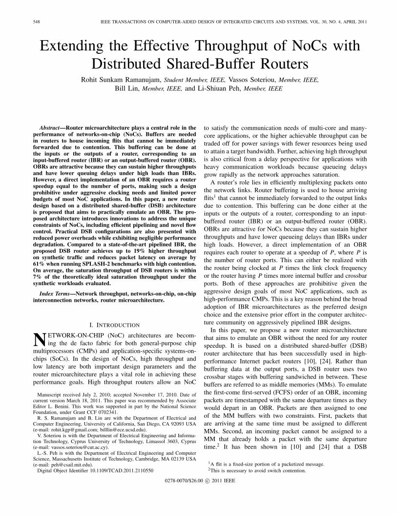
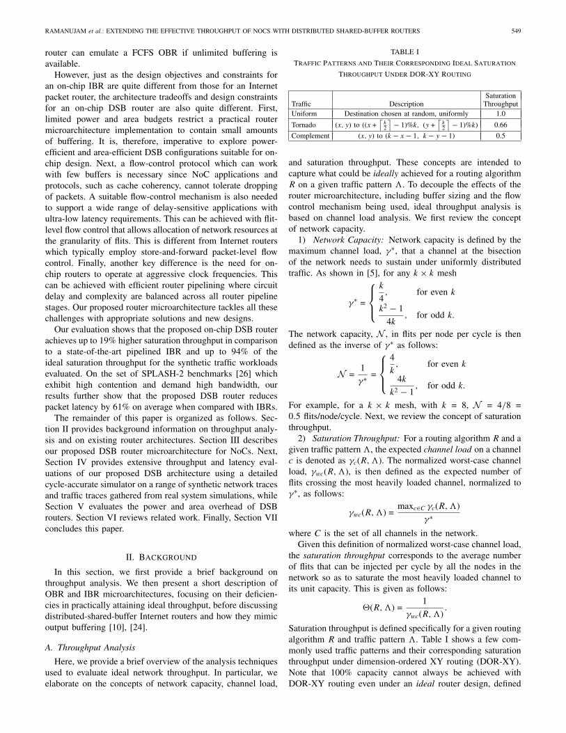
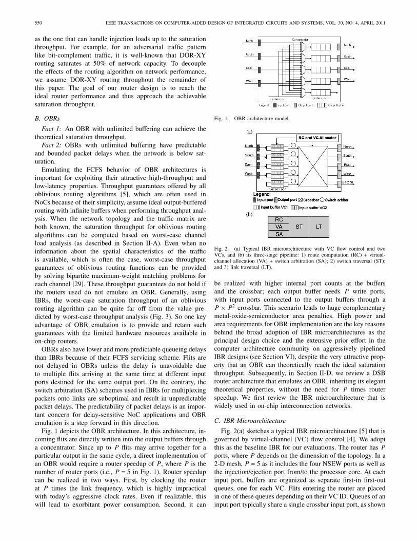
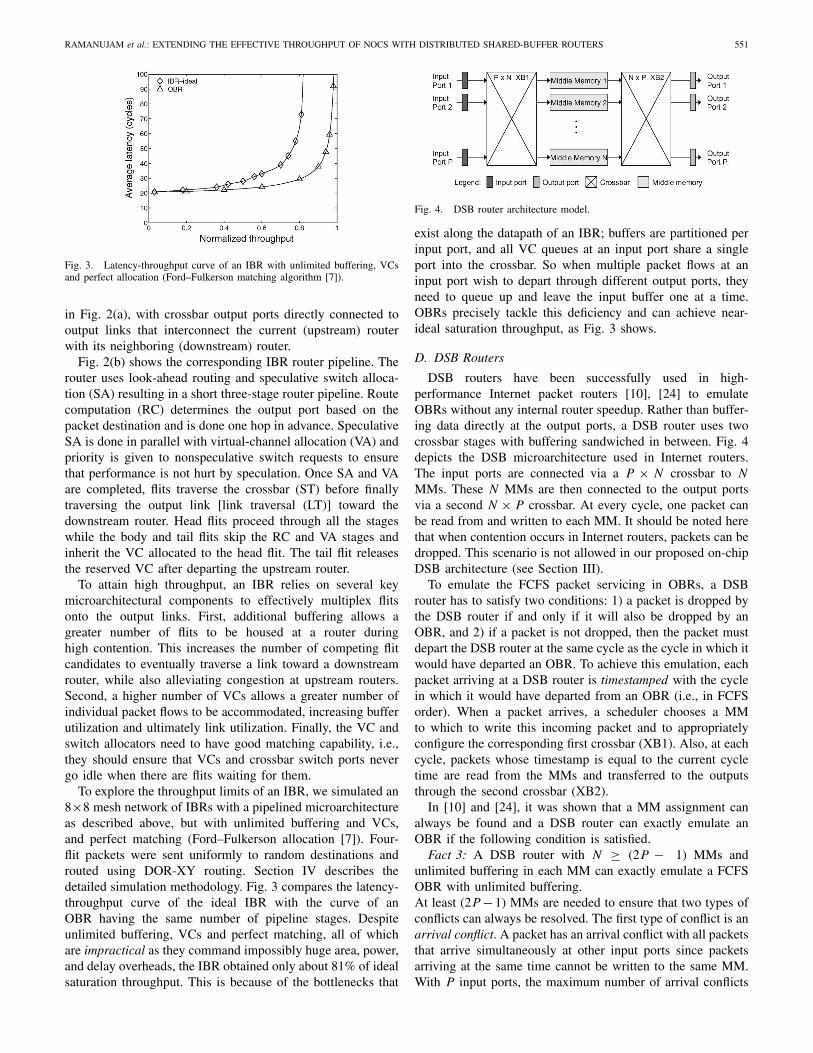
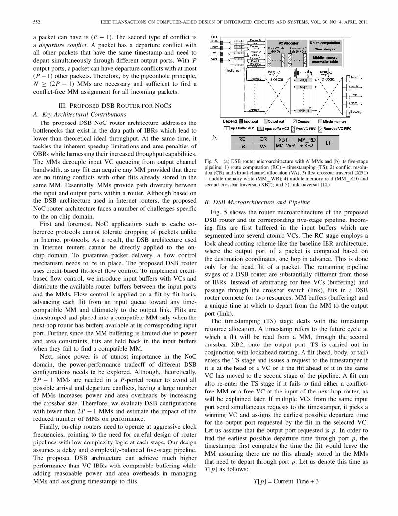
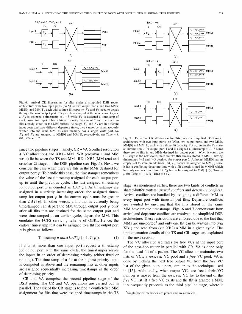
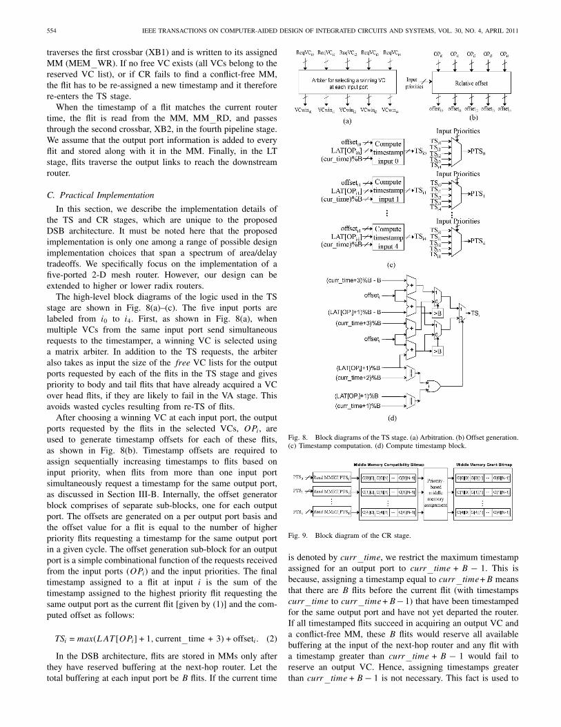
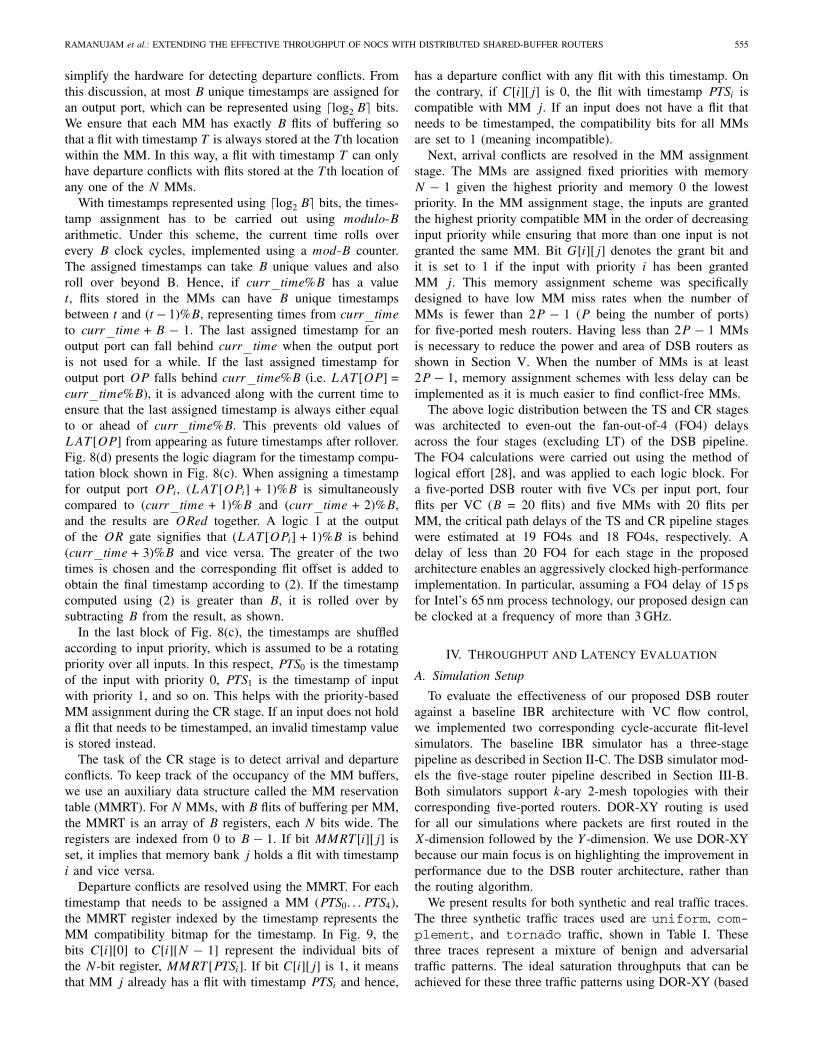
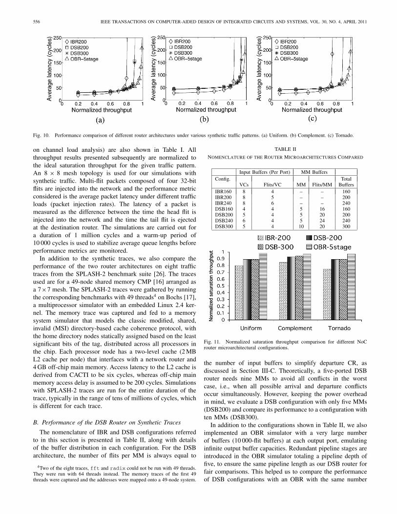
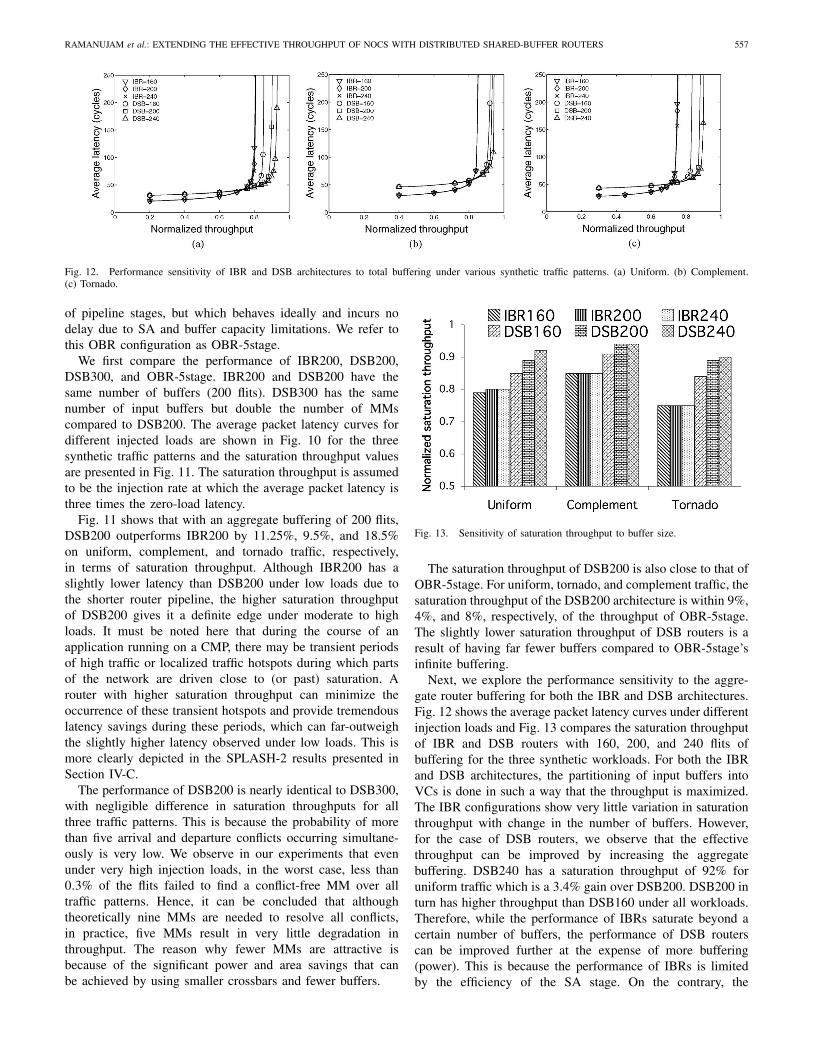
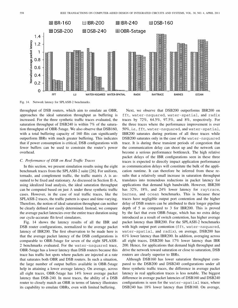
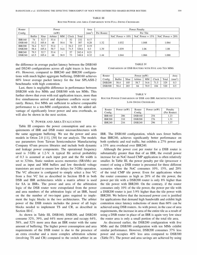


![Process: Unity [9441] Identifier: com.unity3d.UnityEditor5 ... · 34 com.unity3d.UnityEditor5.x 0x00000001010366a8 void ExecuteSerializationCommands(dynamic_array](https://static.documents.pub/doc/80x56/5e7d46b4c53f18402f268721/process-unity-9441-identiier-com-34-com-0x00000001010366a8-void-executeserializationcommandsdynamicarray.jpg)
![Chapter 8 Design of Application-Specific 3D Networks-on ...cwcserv.ucsd.edu/~billlin/recent/springer10_3D.pdf · the global communication challenges in nanoscale SoC designs [1, 2].](https://static.documents.pub/doc/80x56/5ff8d957f2b318722f44ad1e/chapter-8-design-of-application-specific-3d-networks-on-billlinrecentspringer103dpdf.jpg)

![Process: SweetHome3D [652] Identifier: com.eteks ...€¦Path: /Applications/Sweet Home 3D.app/Contents/MacOS/SweetHome3D Identifier ... Crashed Thread: 22 Java: J3D-Renderer-1 Exception](https://static.documents.pub/doc/80x56/5b51b58a7f8b9af4408c7d9c/process-sweethome3d-652-identier-cometeks-applicationssweet-home-3dappcontentsmacossweethome3d.jpg)


