D1U54P-W-1500-12-HxxTC Series 54mm 1U Front End AC-DC Power Supply Converter http://www.murata-p.com/support D1U54P-W-1500-12-HxxTC.A08 page 1 of 10 Available now at: www.murata-ps.com/en/3d/acdc.html +1500W continuous output power IEC60320-C16 connector for maximized low line operation 94% efficiency at 50% Load 12V main output 3.3V; 5V and 12V standby output Options 1U height: 2.15" x 12.65" x 1.57" > 35 watts per cubic inch density N+1 redundancy, hotpluggble, Ishare compatible with DC input series active (digital) current sharing on 12V main output; integral ORing /isolation device MOSFET internal cooling fan (variable speed) overvoltage, overcurrent, overtemperature protection PMBus™/I²C interface with LED status indicators RoHS compliant two year warranty PRODUCT OVERVIEW The D1U54P-W-1500-12-HxxTC product series offers very high efficiency in a compact form factor. These variants offers 1500 watt, and is a power factor corrected front end supply with a 12Vdc main output and either a 3.3V, 5V or 12V auxiliary/standby output. Active (digital) current sharing is provided and up to eight supplies may be operated in parallel. The supply may be hot plugged, and auto recovers from overtemperature faults, that are reported by a status LEDS on the front panel in addition to logic and PMBus™ status signals. The low profile 1U package and excellent 35W/cubic inch power density it ideal for delivering reliable, efficient power to servers, workstations, storage systems and other 12V distributed power architectures. OUTPUT VOLTAGE CHARACTERISTICS Output Parameter Conditions Min. Typ. Max. Units 12V Nominal Output Voltage 12 Vdc Output Set Point Accuracy 50% load; Tamb =25°C -0.5 +0.5 % Line and Load Regulation 2 Measured at remote sense -1.0 +1.5 Ripple Voltage & Noise 1,2 20MHz Bandwidth 120 mV p-p Output Current 1500W; (115-264Vac) 0 125 A Output Current 1260W; (90-264Vac) 0 105 Load Capacitance 30,000 μF 3.3VSB Nominal Output Voltage 3.3 Vdc Line and Load Regulation 3.14 3.46 Ripple Voltage & Noise 1,3 20MHz Bandwidth 75 mV p-p Output Current 0 4 A Load Capacitance 0 3000 μF 5VSB Nominal Output Voltage 5.0 Vdc Line and Load Regulation 4.76 5.24 Ripple Voltage & Noise 1,3 20MHz Bandwidth 75 mV p-p Output Current 0 4 A Load Capacitance 0 3000 μF 12VSB Nominal Output Voltage 12 Vdc Line and Load Regulation 11.7 12.3 Ripple Voltage & Noise 1,3 120 mV p-p Output Current 0 2.5 A Load Capacitance 1000 μF Ripple and noise are measured with 0.1 μF of ceramic capacitance and 10 μF of tantalum capacitance on each of the power supply outputs. A short coaxial cable to the scope termination is used. Minimum Load of 5A. Minimum Load of 0.25A. ORDERING GUIDE Part Number Power Output Input Voltage (200-240 Vac) 45°C Power Output Input Voltage (110-120 Vac) 45°C Power Output Input Voltage (100 Vac) 40°C Main Output Standby Output Airflow D1U54P-W-1500-12-HC4TC 1500W 1400W 1260W 12Vdc 3.3Vdc Back to Front D1U54P-W-1500-12-HA4TC 5Vdc D1U54P-W-1500-12-HB4TC 12Vdc D1U54P-W-1500-12-HC3TC 3.3Vdc Front to Back D1U54P-W-1500-12-HA3TC 5Vdc 1 The HAxTC variants are certified for compliance to 80 PLUS ® Platinum efficiency requirements. INPUT CHARACTERISTICS Parameter Conditions Min. Nom. Max. Units Input Voltage Operating Range 90 115/230 264 Vac Input Frequency 47 50/60 63 Hz Turn-on Input Voltage Ramp up 74 84 Vac Turn-off Input Voltage Ramp down 70 80 Maximum current Vin = 100 Vac/60Hz; 1260W 15 Arms Inrush Current Cold start between 0 to 200msec, 264Vac 50 Apk Power Factor At 230Vac, full load 0.99 Efficiency (230Vac) excluding fan load 20% load 90 % 50% load 94 100% load 91 FEATURES For full details go to www.murata-ps.com/rohs CB
Transcript
D1U54P-W-1500-12-HxxTC Series 54mm 1U Front End AC-DC Power Supply Converter
http://www.murata-p.com/support D1U54P-W-1500-12-HxxTC.A08 page 1 of 10
Available now at: www.murata-ps.com/en/3d/acdc.html
+1500W continuous output power IEC60320-C16 connector for maximized
low line operation 94% efficiency at 50% Load 12V main output 3.3V; 5V and 12V standby output Options 1U height: 2.15" x 12.65" x 1.57" > 35 watts per cubic inch density N+1 redundancy, hotpluggble, Ishare
compatible with DC input series active (digital) current sharing on 12V
main output; integral ORing /isolationdevice MOSFET
internal cooling fan (variable speed)overvoltage, overcurrent,overtemperature protection
PMBus™/I²C interface with LED statusindicators
RoHS compliant two year warranty
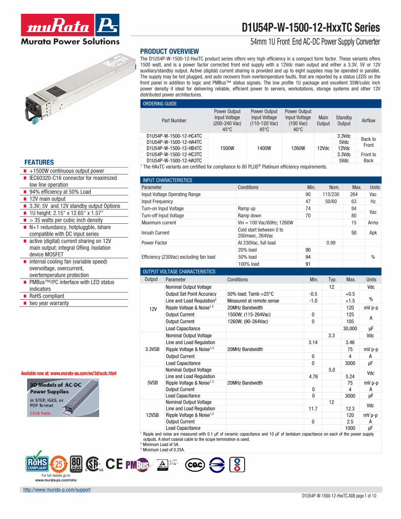
PRODUCT OVERVIEW The D1U54P-W-1500-12-HxxTC product series offers very high efficiency in a compact form factor. These variants offers 1500 watt, and is a power factor corrected front end supply with a 12Vdc main output and either a 3.3V, 5V or 12V auxiliary/standby output. Active (digital) current sharing is provided and up to eight supplies may be operated in parallel. The supply may be hot plugged, and auto recovers from overtemperature faults, that are reported by a status LEDS on the front panel in addition to logic and PMBus™ status signals. The low profile 1U package and excellent 35W/cubic inch power density it ideal for delivering reliable, efficient power to servers, workstations, storage systems and other 12V distributed power architectures.
OUTPUT VOLTAGE CHARACTERISTICS Output Parameter Conditions Min. Typ. Max. Units
12V
Nominal Output Voltage 12 Vdc Output Set Point Accuracy 50% load; Tamb =25°C -0.5 +0.5
% Line and Load Regulation2 Measured at remote sense -1.0 +1.5 Ripple Voltage & Noise1,2
A Output Current 1260W; (90-264Vac) 0 105 Load Capacitance 30,000 μF
3.3VSB
Nominal Output Voltage 3.3 Vdc Line and Load Regulation 3.14 3.46 Ripple Voltage & Noise1,3 20MHz Bandwidth 75 mV p-p Output Current 0 4 A Load Capacitance 0 3000 μF
5VSB
Nominal Output Voltage 5.0 Vdc
Line and Load Regulation 4.76 5.24 Ripple Voltage & Noise1,3 20MHz Bandwidth 75 mV p-p Output Current 0 4 A Load Capacitance 0 3000 μF
12VSB
Nominal Output Voltage 12 Vdc
Line and Load Regulation 11.7 12.3 Ripple Voltage & Noise1,3 120 mV p-p Output Current 0 2.5 A Load Capacitance 1000 μF
1 Ripple and noise are measured with 0.1 μF of ceramic capacitance and 10 μF of tantalum capacitance on each of the power supply outputs. A short coaxial cable to the scope termination is used.
2 Minimum Load of 5A.3 Minimum Load of 0.25A.
ORDERING GUIDE
Part Number
Power Output Input Voltage (200-240 Vac)
45°C
Power Output Input Voltage (110-120 Vac)
45°C
Power Output Input Voltage
(100 Vac) 40°C
Main Output
Standby Output Airflow
D1U54P-W-1500-12-HC4TC
1500W 1400W 1260W 12Vdc
3.3Vdc Back to Front D1U54P-W-1500-12-HA4TC 5Vdc
D1U54P-W-1500-12-HB4TC 12Vdc D1U54P-W-1500-12-HC3TC 3.3Vdc Front to
Back D1U54P-W-1500-12-HA3TC 5Vdc 1 The HAxTC variants are certified for compliance to 80 PLUS® Platinum efficiency requirements.
INPUT CHARACTERISTICS Parameter Conditions Min. Nom. Max. Units Input Voltage Operating Range 90 115/230 264 Vac Input Frequency 47 50/60 63 Hz Turn-on Input Voltage Ramp up 74 84
Vac Turn-off Input Voltage Ramp down 70 80 Maximum current Vin = 100 Vac/60Hz; 1260W 15 Arms
Inrush Current Cold start between 0 to 200msec, 264Vac 50 Apk
Power Factor At 230Vac, full load 0.99
Efficiency (230Vac) excluding fan load 20% load 90
STATUS INDICATORS AND CONTROL SIGNALS (BI_COLOUR LED) GREEN AMBER Condition LED Status (Power) LED Status (Fault) Standby - ON; Main output - OFF; AC PRESENT Blinking green Off Standby - ON; Main output - ON Solid green Off Main output overcurrent, undervoltage, overvoltage1 Off On FAN_FAULT; overtemperature; standby overcurrent, undervoltage1 Off On No AC Power Off Off Power Supply Warning Event1 Off Blinking 1 reported also by PMBus Status Register(s) and asserts SMB_Alert
ADDR ADDRESS SELECTION ADDR pin (A3) resistor to GND (K-ohm)*
Power Supply Main Controller (Serial Communications Slave Address)
Power Supply External EEPROM (Serial Communications Slave Address)
D1U54P-W-1500-12-HxxTC Series 54mm 1U Front End AC-DC Power Supply Converter
http://www.murata-p.com/support D1U54P-W-1500-12-HxxTC.A08 page 4 of 10
STATUS AND CONTROL SIGNALS
Signal Name I/O Description Interface Details
INPUT_OK (AC Source) Output
The signal output is driven high when input source is available and within acceptable limits. The output is driven low to indicate loss of input power. There is a minimum of 1ms pre-warning time before the signal is driven low prior to the PWR_OK signal going low. The power supply must ensure that this interface signal provides accurate status when AC power is lost.
Pulled up internally via 10K to VDD1. A logic high >2.0Vdc A logic low <0.8Vdc Driven low by internal CMOS buffer (open drain output).
PW_OK (Output OK) Output The signal is asserted, driven high, by the power supply to indicate that all outputs are valid. If any of the outputs fail then this output will be hi-Z or driven low. The output is driven low to indicate that the Main output is outside of lower limit of regulation (11.4Vdc).
Pulled up internally via 10K to VDD1. A logic high >2.0Vdc A logic low <0.8Vdc Driven low by internal CMOS buffer (open drain output).
SMB_ALERT (FAULT/WARNING) Output
The signal output is driven low to indicate that the power supply has detected a warning or fault and is intended to alert the system. This output must be driven high when the power is operating correctly (within specified limits). The signal will revert to a high level when the warning/fault stimulus (that caused the alert) is removed. SMB_Alert and LED Fault / warn status assert together. CML errors do not impact SMB_Alert and LED status.
Pulled up internally via 10K to VDD1. A logic high >2.0Vdc A logic low <0.8Vdc Driven low by internal CMOS buffer (open drain output).
PRESENT_L (Power Supply Absent) Output The signal is used to detect the presence (installed) of a PSU by the host system. The signal is
connected to PSU logic SGND within the power module.
Passive connection to +VSB_Return. A logic low <0.8Vdc
PS_ON (Power Supply Enable/Disable
Input
This signal is pulled up internally to the internal housekeeping supply (within the power supply). The power supply main 12Vdc output will be enabled when this signal is pulled low to +VSB_Return. In the low state the signal input shall not source more than 1mA of current. The 12Vdc output will be disabled when the input is driven higher than 2.4V, or open circuited. Cycling this signal shall clear latched fault conditions.
Pulled up internally via 10K to VDD1. A logic high >2.0Vdc A logic low <0.8Vdc Input is via CMOS Schmitt trigger buffer.
PS_KILL Input This signal is used during hot swap to disable the main output during hot swap extraction. The input is pulled up internally to the internal housekeeping supply (within the power supply). The signal is provided on a short (lagging pin) and should be connected to +VSB_Return.
Pulled up internally via 10K to VDD1. A logic high >2.0Vdc A logic low <0.8Vdc Input is via CMOS Schmitt trigger buffer.
ADDR (Address Select) Input
An analog input that is used to set the address of the internal slave devices (EEPROM and microprocessor) used for digital communications. Connection of a suitable resistor to +VSB_Return, in conjunction with an internal resistor divider chain, will configure the required address.
DC voltage between the limits of 0 and +3.3Vdc.
SCL (Serial Clock) Both
A serial clock line compatible with PMBusTM Power Systems Management Protocol Part 1 – General Requirements Rev 1.1. No additional internal capacitance is added that would affect the speed of the bus. The signal is provided with a series isolator device to disconnect the internal power supply bus in the event that the power module is unpowered.
VIL is 0.8V maximum VOL is 0.4V maximum when sinking 3mA VIH is 2.1V minimum
SDA (Serial Data) Both
A serial data line compatible with PMBusTM Power Systems Management Protocol Part 1 – General Requirements Rev 1.1. The signal is provided with a series isolator device to disconnect the internal power supply bus in the event that the power module is unpowered.
VIL is 0.8V maximum VOL is 0.4V maximum when sinking 3mA VIH is 2.1V minimum
V1_SENSE V1SENSE_RTN
Input
Remote sense connections intended to be connected at and sense the voltage at the point of load. The voltage sense will interact with the internal module regulation loop to compensate for voltage drops due to connection resistance between the output connector and the load. If remote sense compensation is not required then the voltage can be configured for local sense by: 1. V1_SENSE directly connected to power blades 6 to 10 (inclusive) 2. V1_SENSE_RTN directly connected to power blades 1 to 5 (inclusive)
Compensation for up to 0.12Vdc total connection drop (output and return connections).
ISHARE
Bi-Directional Analogue
Bus
The current sharing signal is connected between sharing units (forming an ISHARE bus). It is an input and/or an output (bi-directional analog bus) as the voltage on the line controls the current share between sharing units. A power supply will respond to a change in this voltage but a power supply can also change the voltage depending on the load drawn from it. On a single unit the voltage on the pin (and the common ISHARE bus would read 8VDC at 100% load (module capability). For two identical units sharing the same 100% load this would read 4VDC for perfect current sharing (i.e. 50% module load capability per unit).
Analogue voltage: +8V maximum; 10K to +12V_RTN
1. VDD is an internal voltage rail derived from VSB and an internal housekeeping rail (“diode ORed”) and is compatible with the voltage levels of TTL and CMOS logic families.
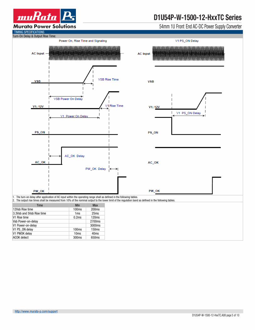
1. The turn-on delay after application of AC input within the operating range shall as defined in the following tables. 2. The output rise times shall be measured from 10% of the nominal output to the lower limit of the regulation band as defined in the following tables.
Time Min Max 12Vsb Rise time 100ms 200ms 3.3Vsb and 5Vsb Rise time 1ms 25ms V1 Rise time 0.2ms 120ms Vsb Power-on-delay 2700ms V1 Power-on-delay 3000ms V1 PS_ON delay 100ms 150ms V1 PWOK delay 10ms 40ms ACOK detect 300ms 650ms
D1U54P-W-1500-12-HxxTC Series 54mm 1U Front End AC-DC Power Supply Converter
http://www.murata-p.com/support D1U54P-W-1500-12-HxxTC.A08 page 7 of 10
0
50
100
150
200
250
300
350
400
450
0 2 4 6 8 10 12 14
Back
Pre
ssur
e (P
a)
PSU airflow (CFM)
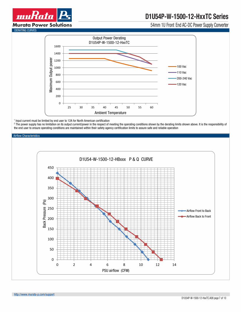
D1U54-W-1500-12-HBxxx P & Q CURVE
Airflow Front to Back
Airflow Back to Front
DERATING CURVES
1 Input current must be limited by end user to 12A for North American certification 2 The power supply has no limitation on its output current/power in the respect of meeting the operating conditions shown by the derating limits shown above. It is the responsibility of the end user to ensure operating conditions are maintained within their safety agency certification limits to assure safe and reliable operation
D1U54P-W-1500-12-HxxTC Series 54mm 1U Front End AC-DC Power Supply Converter
http://www.murata-p.com/support D1U54P-W-1500-12-HxxTC.A08 page 8 of 10
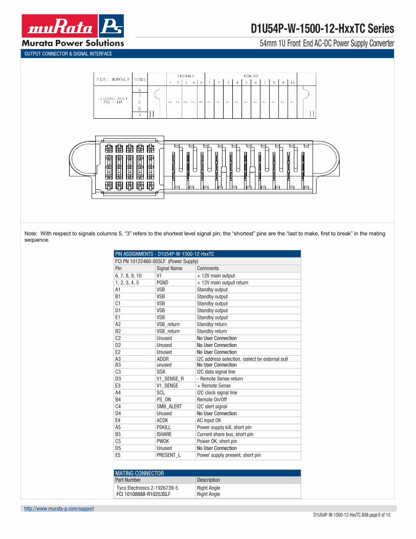
OUTPUT CONNECTOR & SIGNAL INTERFACE
Note: With respect to signals columns 5, “3” refers to the shortest level signal pin; the “shortest” pins are the “last to make, first to break” in the mating sequence.
PIN ASSIGNMENTS - D1U54P-W-1500-12-HxxTC FCI PN 10122460-005LF (Power Supply) Pin Signal Name Comments 6, 7, 8, 9, 10 V1 + 12V main output 1, 2, 3, 4, 5 PGND + 12V main output return A1 VSB Standby output B1 VSB Standby output C1 VSB Standby output D1 VSB Standby output E1 VSB Standby output A2 VSB_return Standby return B2 VSB_return Standby return C2 Unused No User Connection D2 Unused No User Connection E2 Unused No User Connection A3 ADDR I2C address selection, (select by external pull
B3 unused No User Connection C3 SDA I2C data signal line D3 V1_SENSE_R - Remote Sense return E3 V1_SENSE + Remote Sense A4 SCL I2C clock signal line B4 PS_ON Remote On/Off C4 SMB_ALERT I2C alert signal D4 Unused No User Connection E4 ACOK AC input OK A5 PSKILL Power supply kill, short pin B5 ISHARE Current share bus, short pin C5 PWOK Power OK, short pin D5 Unused No User Connection E5 PRESENT_L Power supply present, short pin
D1U54P-W-1500-12-HxxTC Series 54mm 1U Front End AC-DC Power Supply Converter
http://www.murata-p.com/support D1U54P-W-1500-12-HxxTC.A08 page 9 of 10
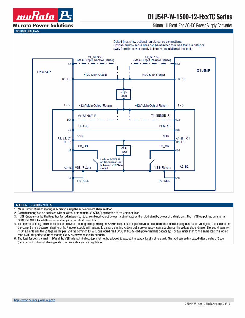
WIRING DIAGRAM
CURRENT SHARING NOTES 1. Main Output: Current sharing is achieved using the active current share method. 2. Current sharing can be achieved with or without the remote (V_SENSE) connected to the common load. 3. +VSB Outputs can be tied together for redundancy but total combined output power must not exceed the rated standby power of a single unit. The +VSB output has an internal
ORING MOSFET for additional redundancy/internal short protection. 4. The current sharing pin B5 is connected between sharing units (forming an ISHARE bus). It is an input and/or an output (bi-directional analog bus) as the voltage on the line controls
the current share between sharing units. A power supply will respond to a change in this voltage but a power supply can also change the voltage depending on the load drawn from it. On a single unit the voltage on the pin (and the common ISHARE bus would read 8VDC at 100% load (power module capability). For two units sharing the same load this would read 4VDC for perfect current sharing (i.e. 50% power capability per unit).
5. The load for both the main 12V and the VSB rails at initial startup shall not be allowed to exceed the capability of a single unit. The load can be increased after a delay of 3sec (minimum), to allow all sharing units to achieve steady state regulation.
D1U54P-W-1500-12-HxxTC Series 54mm 1U Front End AC-DC Power Supply Converter
http://www.murata-p.com/support D1U54P-W-1500-12-HxxTC.A08 page 10 of 10
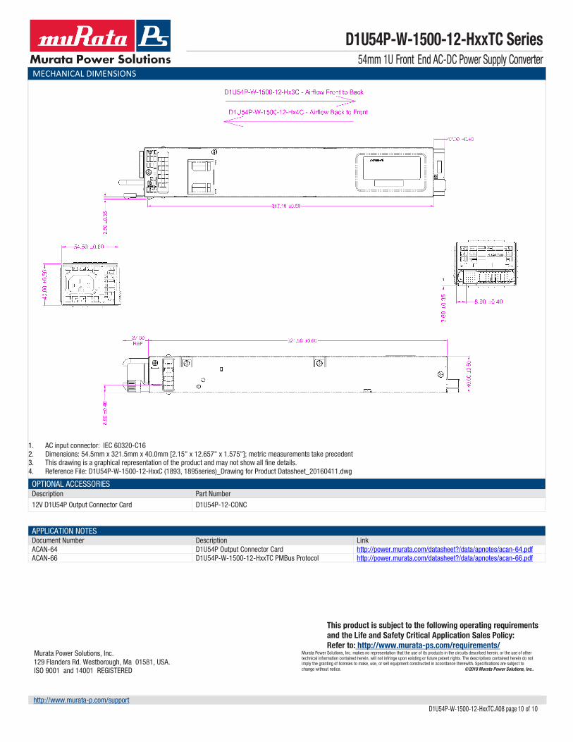
MECHANICAL DIMENSIONS
1. AC input connector: IEC 60320-C16 2. Dimensions: 54.5mm x 321.5mm x 40.0mm [2.15" x 12.657" x 1.575"]; metric measurements take precedent 3. This drawing is a graphical representation of the product and may not show all fine details. 4. Reference File: D1U54P-W-1500-12-HxxC (1893, 1895series)_Drawing for Product Datasheet_20160411.dwg
OPTIONAL ACCESSORIES Description Part Number
12V D1U54P Output Connector Card D1U54P-12-CONC
APPLICATION NOTES Document Number Description Link ACAN-64 D1U54P Output Connector Card http://power.murata.com/datasheet?/data/apnotes/acan-64.pdf ACAN-66 D1U54P-W-1500-12-HxxTC PMBus Protocol http://power.murata.com/datasheet?/data/apnotes/acan-66.pdf
Murata Power Solutions, Inc. 129 Flanders Rd. Westborough, Ma 01581, USA.
ISO 9001 and 14001 REGISTERED
This product is subject to the following operating requirements and the Life and Safety Critical Application Sales Policy: Refer to: http://www.murata-ps.com/requirements/