Classic Performance Products, Inc. 714.522.2000 | fax 714.522.2500 378 E. Orangethorpe Ave. | Placentia, CA 92870 | www.classicperform.com Steering, Brake & Suspension Specialists Rev. 08/15/2017 # 5556OSC-AK-NS Original Automatic Steering Column Instructions for 1955-56 Chevy Bel Air This photo shows that with the old style column conversion, the seal to the firewall is poor as well as needing to cut a larger hole to slip the shift arm through. (FIG. A) PLEASE NOTE: The installer needs to make sure that nothing can make contact with a brake hose, caliper, or other brake component at any point through the entire range of steering and suspension movement. The installer also needs to make sure none of the steering or braking components can become bound or jammed at any time through the range of suspension or steering movement. D A B C Instructions: 1. Remove the existing steering column from the car. With the column removed, you can see the difference in mounting points for the detent and shift arm. CPP column on left. (FIG. C) Remove the turn signal lever and the shift arm. Next, remove the three turn signal housing screws that hold it to the column and carefully pull the housing off and pull the wires out of the column. 2. Once separated from the column, remove the three prong turn signal housing lock plate and then slip the collar off the column tube. Lastly, remove the notched retaining ring. All these parts will be re-used on the new column. # 5556OSC-AK-NS Shown The shift detent on the old style conversion does not allow the factory seal to fit correctly and will not let the carpet lay flat. (FIG. B) 3. Before assembling the CPP column, apply a small amount of anti-seize to the inner tube. This will allow for smoother shifting. (FIG. D) Continued on Next Page
Transcript
Classic Performance Products, Inc. 714.522.2000 | fax 714.522.2500 378 E. Orangethorpe Ave. | Placentia, CA 92870 | www.classicperform.com
Steering, Brake & Suspension Specialists
Rev. 08/15/2017
#5556OSC-AK-NS Original Automatic Steering Column Instructionsfor 1955-56 Chevy Bel Air
This photo shows that with the old style column conversion, the seal to the firewall is poor as well as needing to cut a larger hole to slip the shift arm through. (FIG. A)
PLEASE NOTE: The installer needs to make sure that nothing can make contact with a brake hose, caliper, or other brake component at any point through the entire range of steering and suspension movement. The installer also needs to make sure none of the steering or braking components can become bound or jammed at any time through the range of suspension or steering movement.
D
A
B
C
Instructions:
1. Remove the existing steering column from the car. With the column removed, you can see the difference in mounting points for the detent and shift arm. CPP column on left. (FIG. C) Remove the turn signal lever and the shift arm. Next, remove the three turn signal housing screws that hold it to the column and carefully pull the housing off and pull the wires out of the column.
2. Once separated from the column, remove the three prong turn signal housing lock plate and then slip the collar off the column tube. Lastly, remove the notched retaining ring. All these parts will be re-used on the new column.
#5556OSC-AK-NS Shown
The shift detent on the old style conversion does not allow the factory seal to fit correctly and will not let the carpet lay flat. (FIG. B)
3. Before assembling the CPP column, apply a small amount of anti-seize to the inner tube. This will allow for smoother shifting. (FIG. D)
Continued on Next Page
Classic Performance Products, Inc. 714.522.2000 | fax 714.522.2500 378 E. Orangethorpe Ave. | Placentia, CA 92870 | www.classicperform.com
Steering, Brake & Suspension Specialists
Rev. 08/15/2017
F1
4. When installing the inner tube notched retaining ring, it might be
necessary to press down the three tabs to allow the retaining ring to sit on without falling down inside the column. (FIG. E1-E2)
E1 E2
H I
G
F2 F3
#5556OSC-AK-NS Original Automatic Steering Column Instructionsfor 1955-56 Chevy Bel Air (Continued)
5. Before installing the shift collar, apply a small amount of anti-seize to the end to ensure a smooth operation. Re-install the factory turn signal housing lock plate and turn it until it locks under the tabs on the column. (FIG. F1-F3)
6. Re-install the turn signal housing to the column. You will need to fish the turn signal wires down the inside of the column and out the factory hole. (FIG. G)
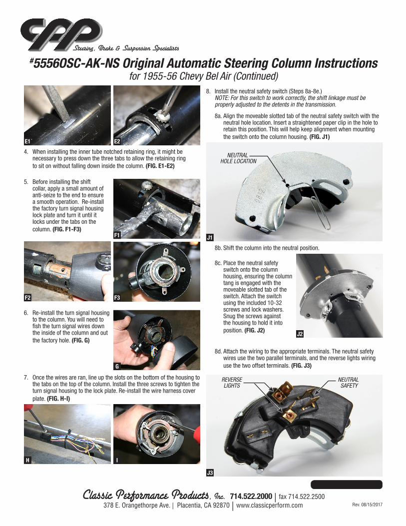
8. Install the neutral safety switch (Steps 8a-8e.) NOTE: For this switch to work correctly, the shift linkage must be properly adjusted to the detents in the transmission.
7. Once the wires are ran, line up the slots on the bottom of the housing to the tabs on the top of the column. Install the three screws to tighten the turn signal housing to the lock plate. Re-install the wire harness cover plate. (FIG. H-I)
J2
8b. Shift the column into the neutral position.
Continued on Next Page
8c. Place the neutral safety switch onto the column housing, ensuring the column tang is engaged with the moveable slotted tab of the switch. Attach the switch using the included 10-32 screws and lock washers. Snug the screws against the housing to hold it into position. (FIG. J2)
8d. Attach the wiring to the appropriate terminals. The neutral safety wires use the two parallel terminals, and the reverse lights wiring use the two offset terminals. (FIG. J3)
J1
NEUTRAL HOLE LOCATION
J3
NEUTRAL SAFETY
REVERSE LIGHTS
8a. Align the moveable slotted tab of the neutral safety switch with the neutral hole location. Insert a straightened paper clip in the hole to retain this position. This will help keep alignment when mounting the switch onto the column housing. (FIG. J1)
Classic Performance Products, Inc. 714.522.2000 | fax 714.522.2500 378 E. Orangethorpe Ave. | Placentia, CA 92870 | www.classicperform.com
CPP column shown assembled with the factory shift collar and turn signal housing. (FIG. K)
8e. The engine should only start in park or neutral. Reverse lights should turn on when shifted in reverse. Loosen the attaching screws and adjust switch position as needed. Tighten the attaching screws once properly adjusted.
9. To install the rag joint, a ¼” hole must be drilled to secure the rag joint to the shaft with the roll pin supplied. Next, from the inside of the car, install the rag joint/shaft to the steering box and tighten. Slide the floor plate onto the bottom end of the CPP column. Then slide the new CPP column over the steering shaft and out through the bottom of the floor board. Secure the column to the dash using the factory column clamp. (FIG. L1-L2)
K
M
N
#5556OSC-AK-NS Original Automatic Steering Column Instructionsfor 1955-56 Chevy Bel Air (Continued)
10. Secure the base of the column
to the floor using the CPP floor plate and column clamp. With this kit, you can see how much cleaner it fits to the floor board. (FIG. M)
L1 L2
11. Next hook up the transmission shift linkage. The outside of the firewall is much cleaner as well with the CPP column. (FIG. N)
12. Reinstall the shift and turn signal levers. The CPP column is completely installed and still retains the classic factory look.
NOTES:The correct gap between the steering wheel and turn signal housing can be obtained by how far up or down the column is bolted to the bottom side of the dash using the factory under dash mount. The under dash mount is slotted to allow for adjustment. Before you drill and pin the rag joint to the shaft, first install the rag joint to the steering box. Slide the shaft through the firewall from inside the car into the rag joint. Install the column over the shaft and bolt it in place with the factory under dash mount. Now install the steering wheel. By sliding the column up or down through the mount, you can adjust the gap between the turn signal housing and steering wheel. If no further adjustment is needed, remove the column from the car. Drill and pin the rag joint as shown in (Fig. L1). If further adjustment is needed due to different brands of steering wheels and adapters, there is some adjustment in the rag joint placement on the shaft. By moving the inner shaft up or down in the rag joint will help with the gap between the steering wheel and turn signal housing. Mark the rag joint on the shaft where the hole needs to be drilled. Make sure there is enough room to pin the rag joint to the shaft and that you will not be drilling to close to the end of the shaft. Remove the column, rag joint and shaft from the car. Drill and pin the rag joint as shown in (Fig. L1).
In some rare cases, your factory body mount bushings are worn and/or your frame has been hit may cause some minor issues with installing this column. If the body mounts are worn from years of wear and tear, the body may have sagged causing the column to come closer to the rag joint and gear box. It might be necessary to trim the top of the rag joint for clearance if it rubs the column housing or replace your worn out body bushings.