The official directions are written in Chinese, this English edition is for your reference only 56-1 Electromagnetic Compatibility 56-1 Electromagnetic Compatibility Refer to: R10 03-S1 56-1.1 Effective date and Scope: 56-1.1.1 Effective date from 2013/01/01, the new vehicle variants of L category and from 2015/01/01, all vehicle variants of L category shall comply with “56-1 Electromagnetic Compatibility”. Those had already comply with “56 Electromagnetic Compatibility” shall conform to Electromagnetic immunity requirements of “56-1 Electromagnetic Compatibility”. 56-1.1.2 Effective date from 2014/01/01, the new vehicle variants of M,N and O categories shall comply with “56-1 Electromagnetic Compatibility” 56-1.1.3 Effective date From 2016/01/01, each electric vehicle variants of M,N and O categories shall comply with this regulation. Those had already comply with “56 Electromagnetic Compatibility” shall comply with Electromagnetic immunity requirements of “56-1 Electromagnetic Compatibility”. 56-1.1.4 Effective date From 2016/01/01, each non-electric vehicle variants of M1 and N1 categories, from 2017/01/01, each non-electric vehicle variants of M2, M3,N2 and N3 categories, and from 2018/01/01, all non-electric vehicle variants of O category shall comply with this regulation. Those non-electric vehicle variants of M1 and N1 categories had already comply with “56 Electromagnetic Compatibility” shall comply with Electromagnetic immunity requirements of “56-1 Electromagnetic Compatibility”. 56-1.1.5 The same applicant applying for low volume safety approval and the amounts of vehicle not exceed 3 at same year and the category symbols M1,N1, L3 or L5 of same variant and specification, could exempt the Electromagnetic immunity requirement of this regulation. 56-1.1.6 The same applicant applying for vehicle-by-vehicle low volume safety approval and the amounts of vehicle not exceed 20 at same year and vehicle of same variant and specification, could exempt the Electromagnetic immunity requirement of this regulation. 56-1.1.7 For the vehicles used by authorities, organizations, schools or individuals for self-use only could exempt from this regulation of 56-1 Electromagnetic Compatibility. Effective date from 2017/1/1, for the vehicles imported by authorities, organizations, institutes or individuals for self-use, if the vehicle registered and owned by the importer for more than six months from abroad, it could exempt from the regulation of "56-1 Electromagnetic Compatibility ". 56-1.2 Definitions 56-1.2.1 "Electromagnetic compatibility" means the ability of a vehicle or component(s) or separate electrical/electronic technical unit(s) to function satisfactorily in an electromagnetic environment without introducing intolerable electromagnetic disturbances to anything in that environment. 56-1.2.2 "Electromagnetic disturbance" means annoy electromagnetic phenomenon which may degrade the performance of a vehicle or component(s) or separate electrical/electronic technical unit(s). An electromagnetic disturbance may be electromagnetic noise or a -1-
Transcript
The official directions are written in Chinese, this English edition is for your reference only 56-1 Electromagnetic Compatibility
56-1 Electromagnetic CompatibilityRefer to: R10 03-S1
56-1.1 Effective date and Scope:56-1.1.1 Effective date from 2013/01/01, the new vehicle variants of L category and from 2015/01/01, all vehicle variants of L category
shall comply with “56-1 Electromagnetic Compatibility”. Those had already comply with “56 Electromagnetic Compatibility” shall conform to Electromagnetic immunity requirements of “56-1 Electromagnetic Compatibility”.
56-1.1.2 Effective date from 2014/01/01, the new vehicle variants of M,N and O categories shall comply with “56-1 Electromagnetic Compatibility”
56-1.1.3 Effective date From 2016/01/01, each electric vehicle variants of M,N and O categories shall comply with this regulation. Those had already comply with “56 Electromagnetic Compatibility” shall comply with Electromagnetic immunity requirements of “56-1 Electromagnetic Compatibility”.
56-1.1.4 Effective date From 2016/01/01, each non-electric vehicle variants of M1 and N1 categories, from 2017/01/01, each non-electric vehicle variants of M2, M3,N2 and N3 categories, and from 2018/01/01, all non-electric vehicle variants of O category shall comply with this regulation. Those non-electric vehicle variants of M1 and N1 categories had already comply with “56 Electromagnetic Compatibility” shall comply with Electromagnetic immunity requirements of “56-1 Electromagnetic Compatibility”.
56-1.1.5 The same applicant applying for low volume safety approval and the amounts of vehicle not exceed 3 at same year and the category symbols M1,N1, L3 or L5 of same variant and specification, could exempt the Electromagnetic immunity requirement of this regulation.
56-1.1.6 The same applicant applying for vehicle-by-vehicle low volume safety approval and the amounts of vehicle not exceed 20 at same year and vehicle of same variant and specification, could exempt the Electromagnetic immunity requirement of this regulation.
56-1.1.7 For the vehicles used by authorities, organizations, schools or individuals for self-use only could exempt from this regulation of 56-1 Electromagnetic Compatibility. Effective date from 2017/1/1, for the vehicles imported by authorities, organizations, institutes or individuals for self-use, if the vehicle registered and owned by the importer for more than six months from abroad, it could exempt from the regulation of "56-1 Electromagnetic Compatibility ".
56-1.2 Definitions56-1.2.1 "Electromagnetic compatibility" means the ability of a vehicle or component(s) or separate electrical/electronic technical unit(s) to
function satisfactorily in an electromagnetic environment without introducing intolerable electromagnetic disturbances to anything in that environment.
56-1.2.2 "Electromagnetic disturbance" means annoy electromagnetic phenomenon which may degrade the performance of a vehicle or component(s) or separate electrical/electronic technical unit(s). An electromagnetic disturbance may be electromagnetic noise or a
-1-
The official directions are written in Chinese, this English edition is for your reference only 56-1 Electromagnetic Compatibility
change in the propagation medium itself.56-1.2.3 "Electromagnetic immunity" means the ability of a vehicle or component(s) or separate technical unit(s) to perform without
degradation of performance in the presence of specified electromagnetic disturbances.56-1.2.4 "Electromagnetic environment" means the totality of electromagnetic phenomena existing at a given location.56-1.2.5 "Reference limit" means the nominal level to which type approval and conformity of production limit values are referenced.56-1.2.6 "Reference antenna" for the frequency range 20 to 80 MHz: means a shortened balanced resonant dipole at 80 MHz, and for the
frequency range above 80 MHz: means a balanced half-wave resonant dipole tuned to the measurement frequency.56-1.2.7 "Broadband electromagnetic disturbances" means electromagnetic disturbances which have a bandwidth greater than the
passband of the receiver used.56-1.2.8 "Narrowband electromagnetic disturbances" means electromagnetic disturbances which have a bandwidth less than the
passband of the receiver used.56-1.2.9 "Electrical/electronic system" means an electrical and or electronic device or set of devices together with any associated electrical
wiring which forms part of a vehicle but which is not intended to be type approved separately from the vehicle. 56-1.2.10 "Electrical/electronic sub-assembly" (ESA) means an electrical and/or electronic device set of devices intended to be part of a
vehicle, together with any associated electrical wiring, which performs one or more specialized functions. An ESA may be approved at the request of a manufacturer as either a "component" or a "separate technical unit(STU)''.
56-1.2.11 "Immunity related functions" are:(a) Functions related to the direct control of the vehicle:(i) by degradation or change in: e.g. engine, gear, brake, suspension, active steering, speed limitation devices;(ii) by affecting drivers position: e.g. seat or steering wheel positioning;(iii) by affecting driver's visibility: e.g. dipped beam, windscreen wiper.(b) Functions related to driver, passenger and other road user protection:(i) e.g. airbag and safety restraint systems.(c) Functions which when disturbed cause confusion to the driver or other road users:
(i) optical disturbances: incorrect operation of e.g. direction indicators, stop lamps, end outline marker lamps, rear position lamp, light bars for emergency system, wrong information from warning indicators, lamps or displays related to functions in subparagraphs (a) or (b) which might be observed in the direct view of the driver;
(ii) acoustical disturbances: incorrect operation of e.g. anti-theft alarm, horn.(d) Functions related to vehicle data bus functionality:(i) by blocking data transmission on vehicle data bus-systems, which are used to transmit data, required to ensure the correct functioning of other immunity related functions.
(e) Functions which when disturbed affect vehicle statutory data: e.g. tachograph, odometer.56-1.3 Electromagnetic Compatibility shall according to suitable types and range of principle are as below:
-2-
The official directions are written in Chinese, this English edition is for your reference only 56-1 Electromagnetic Compatibility
56-1.3.1 If use completed vehicle for testing, which shall according to suitable variants and range of principle are as below:56-1.3.1.1 The same vehicle category symbol.56-1.3.1.2 The same type of large passenger vehicle body.56-1.3.1.3 The same brand and vehicle type series.56-1.3.1.4 The same chassis brand.56-1.3.1.5 Chassis manufacturers announced that the same chassis vehicle type series.56-1.3.1.6 The same type of vehicle propulsion source (internal combustion engine or pure electric motor or hybrid vehicle).
56-1.3.2 If use chassis vehicle instead of completed vehicle for testing, which shall according to suitable variants and range of principle are as below:
56-1.3.2.1 The same vehicle category.56-1.3.2.2 The same chassis brand.56-1.3.2.3 Chassis manufacturers announced that the same chassis vehicle type series.56-1.3.2.4 The same type of vehicle propulsion source (internal combustion engine or pure electric motor or hybrid vehicle).
56-1.3.3 If use Electrical/Electronic sub-assembly(ESA) for testing, which shall according to suitable variants and range of principle are as below:
56-1.3.3.1 The same ESA brand.56-1.3.3.2 The same ESA type.56-1.3.3.3 The same function performed by the ESA.56-1.3.3.4 The same general arrangement of the electrical and/or electronic components,(If applicable).
56-1.4 Test method descriptions56-1.4.1 General specifications
56-1.4.1.1 A vehicle and its electrical/electronic system(s) or ESA(s) shall be so designed, constructed and fitted as to enable the vehicle, in normal conditions of use, to comply with the requirements of this Regulation.
56-1.4.1.1.1 A vehicle shall be tested for radiated emissions and for immunity to radiated disturbances. No tests for conducted emissions or immunity to conducted disturbances are required for vehicle type approval.
56-1.4.1.1.2 ESA(s) shall be tested for radiated and conducted emissions, for immunity to radiated and conducted disturbances.56-1.4.1.2 Before testing the Technical Service has to prepare a test plan in conjunction with the manufacturer, which contains at least
mode of operation, stimulated function(s), monitored function(s), pass/fail criterion(criteria) and intended emissions.56-1.4.2 Specifications concerning broadband electromagnetic radiation from vehicles.
The official directions are written in Chinese, this English edition is for your reference only 56-1 Electromagnetic Compatibility
The electromagnetic radiation generated by the vehicle representative of its type shall be measured using the method described in paragraph56-1.5. The method of measurement shall be defined by the vehicle manufacturer in accordance with the Technical
Service. 56-1.4.2.2 Vehicle broadband type approval limits
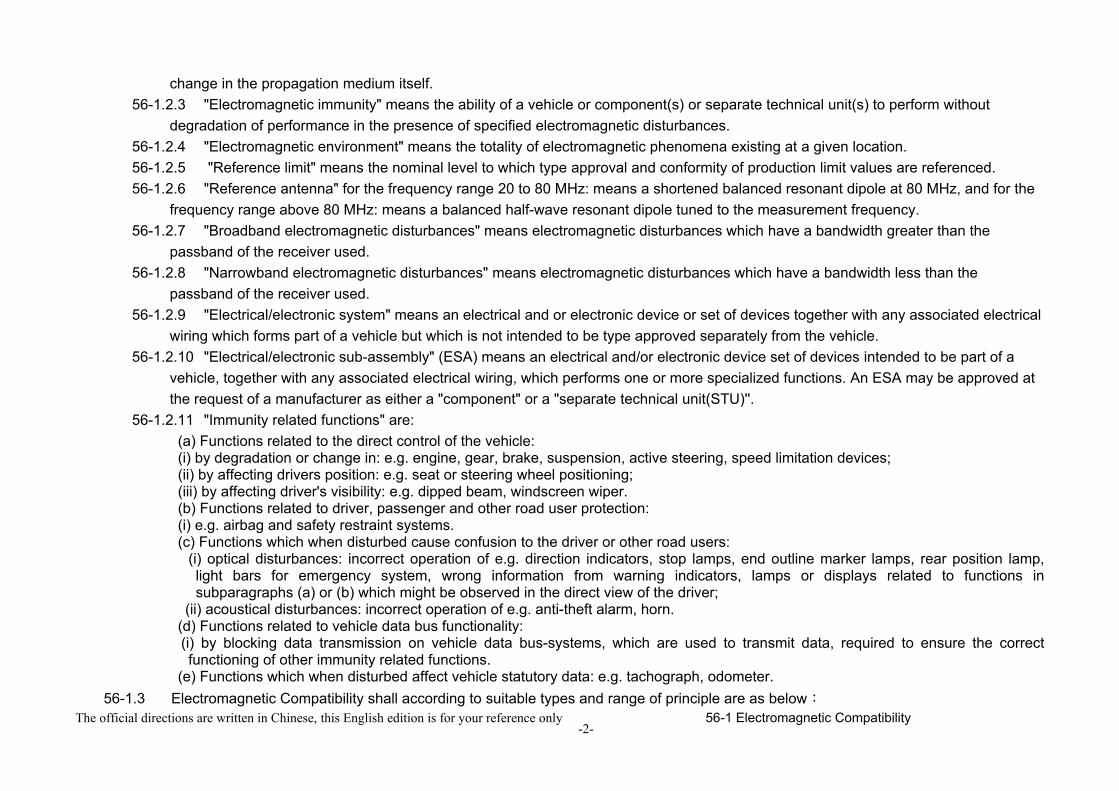
56-1.4.2.2.1 if measurements are made using the method described in paragraph 56-1.5 using a vehicle-to antenna spacing of 10.0 +/- 0.2 m, the limits shall be 32 dB microvolts/m in the 30 to 75 MHz frequency band and 32 to 43 dB microvolts/m in the 75 to 400 MHz frequency band, this limit increasing logarithmically with frequencies above 75 MHz as shown in figure 1. In the 400 to 1,000 MHz frequency band the limit remains constant at 43 dB microvolts/m.
56-1.4.2.2.2 If measurements are made using the method described in paragraph 56-1.5 using a vehicle-toantenna spacing of 3.0 +/- 0.05 m, the limits shall be 42 dB microvolts/m in the 30 to 75 MHz frequency band and 42 to 53 dB microvolts/m in the 75 to 400 MHz frequency band, this limit increasing logarithmically with frequencies above 75 MHz as shown in figure 2. In the 400 to 1,000 MHz frequency band the limit remains constant at 53 dB microvolts/m.
56-1.4.2.2.3 On the vehicle representative of its type, the measured values, expressed in dB microvolts/m shall be below the type approval limits.
56-1.4.3 Specifications concerning narrowband electromagnetic radiation from vehicles56-1.4.3.1 Method of measurement
The electromagnetic radiation generated by the vehicle representative of its type shall be measured using the method described in paragraph 56-1.6. These shall be defined by the vehicle manufacturer in accordance with the Technical Service.
56-1.4.3.2 Vehicle narrowband type approval limits56-1.4.3.2.1 If measurements are made using the method described in paragraph 56-1.6 using a vehicle-to antenna spacing of
10.0 +/- 0.2 m, the limits shall be 22 dB microvolts/m in the 30 to 75 MHz frequency band and 22 to 33 dB microvolts/m in the 75 to 400 MHz frequency band, this limit increasing logarithmically with frequencies above 75 MHz as shown in figure 3. In the 400 to 1,000 MHz frequency band the limit remains constant at 33 dB microvolts/m.
56-1.4.3.2.2 If measurements are made using the method described in paragraph 56-1.6 using a vehicle-toantenna spacing of 3.0 +/- 0.05 m, the limit shall be 32 dB microvolts/m in the 30 to 75 MHz frequency band and 32 to 43 dB microvolts/m in the 75 to 400 MHz frequency band, this limit increasing logarithmically with frequencies above 75 MHz as shown in figure 4. In the 400 to 1,000 MHz frequency band the limit remains constant at 43 dB microvolts/m.
56-1.4.3.2.3 On the vehicle representative of its type, the measured values, expressed in dB microvolts/m, shall be below the type approval limit.
56-1.4.3.2.4 Notwithstanding the limits defined in paragraphs 56-1.4.3.2.1., 56-1.4.3.2.2. and 56-1.4.3.2.3., if, during the initial
-4-
The official directions are written in Chinese, this English edition is for your reference only 56-1 Electromagnetic Compatibility
step described in paragraph 56-1.6, the signal strength measured at the vehicle broadcast radio antenna is less than 20 dB microvolts over the frequency range 76 to 108 MHz measured with an average detector, then the vehicle shall be deemed to comply with the limits for narrowband emissions and no further testing will be required.
56-1.4.4 Specifications concerning immunity of vehicles to electromagnetic radiation56-1.4.4.1 Method of testing
The immunity to electromagnetic radiation of the vehicle representative of its type shall be tested by the method described in paragraph 56-1.9.
56-1.4.4.2 Vehicle immunity type approval limits56-1.4.4.2.1 If tests are made using the method described paragraph 56-1.9, the field strength shall be 30 volts/m rms (root mean
squared) in over 90 per cent of the 20 to 2,000 MHz frequency band and a minimum of 25 volts/m rms over the whole 20 to 2,000 MHz frequency band.
56-1.4.4.2.2 The vehicle representative of its type shall be considered as complying with immunity requirements if, during the tests performed in accordance with paragraph 56-1.9, there shall be no degradation of performance of "immunity related functions".
56-1.4.5 Specification concerning broadband electromagnetic interference generated by ESAs.56-1.4.5.1 Method of measurement
The electromagnetic radiation generated by the ESA representative of its type shall be measured by the method described in paragraph 56-1.7.
56-1.4.5.2 ESA broadband type approval limits56-1.4.5.2.1 If measurements are made using the method described in paragraph 56-1.7, the limits shall be 62 to 52 dB
microvolts/m in the 30 to 75 MHz frequency band, this limit decreasing logarithmically with frequencies above 30 MHz, and 52 to 63 dB microvolts/m in the 75 to 400 MHz band, this limit increasing logarithmically with frequencies above 75 MHz as shown in figure 5. In the 400 to 1,000 MHz frequency band the limit remains constant at 63 dB microvolts/m.
56-1.4.5.2.2 On the ESA representative of its type, the measured values, expressed in dB microvolts/ m, shall be below the type approval limits.
56-1.4.6 Specifications concerning narrowband electromagnetic interference generated by ESAs.56-1.4.6.1 Method of measurement
The electromagnetic radiation generated by the ESA representative of its type shall be measured by the method described paragraph 56-1.8.
56-1.4.6.2 ESA narrowband type approval limits56-1.4.6.2.1 If measurements are made using the method described paragraph 56-1.8, the limits shall be 52 to 42 dB
-5-
The official directions are written in Chinese, this English edition is for your reference only 56-1 Electromagnetic Compatibility
microvolts/m in the 30 to 75 MHz frequency band, this limit decreasing logarithmically with frequencies above 30 MHz, and 42 to 53 dB microvolts/m in the 75 to 400 MHz band, this limit increasing logarithmically with frequencies above 75 MHz as shown figure 6. In the 400 to 1,000 MHz frequency band the limit remains constant at 53 dB microvolts/m.
56-1.4.6.2.2 On the ESA representative of its type, the measured value, expressed in dB microvolts/ m shall be below the type approval limits.
56-1.4.7 Specifications concerning immunity of ESAs to electromagnetic radiation56-1.4.7.1 Method(s) of testing
The immunity to electromagnetic radiation of the ESA representative of its type shall be tested by the method(s) chosen from those described in paragraph 56-1.10.
56-1.4.7.2 ESA immunity type approval limits56-1.4.7.2.1 If tests are made using the methods described in paragraph 56-1.10, the immunity test levels shall be 60 volts/m for
the 150 mm stripline testing method, 15 volts/m for the 800 mm stripline testing method, 75 volts/m for the Transverse Electromagnetic Mode (TEM) cell testing method, 60 mA for the bulk current injection (BCI) testing method and 30 volts/m for the free field testing method in over 90 per cent of the 20 to 2,000 MHz frequency band, and to a minimum of 50 volts/m for the 150 mm stripline testing method, 12.5 volts/m for the 800 mm stripline testing method, 62.5 volts/m, for the TEM cell testing method, 50 mA for the bulk current injection (BCI) testing method and 25 volts/m for the free field testing method over the whole 20 to 2,000 MHz frequency band.
56-1.4.7.2.2 The ESA representative of its type shall be considered as complying with immunity requirements if, during the tests performed in accordance with paragraph 56-1.10, there shall be no degradation of performance of "immunity related functions".
56-1.4.8 Specifications concerning the immunity to transient disturbances conducted along supply lines.56-1.4.8.1 Method of testing
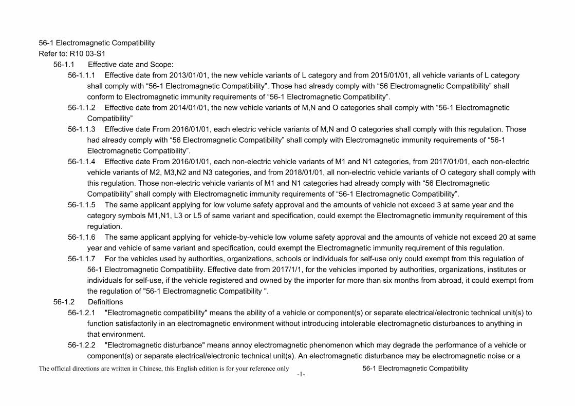
The immunity of ESA representative of its type shall be tested by the method(s) according to ISO 7637-2, second edition 2004 as described in paragraph 56-1.11 with the test levels given table 1.
-6-
The official directions are written in Chinese, this English edition is for your reference only 56-1 Electromagnetic Compatibility
56-1.4.9 Specifications concerning the emission of conducted disturbances56-1.4.9.1 Method of testing
The emission of ESA representative of its type shall be tested by the method(s) according to ISO 7637-2, second edition 2004 as described in paragraph 56-1.11 for the levels given in table 2.
56-1.4.10 Exceptions56-1.4.10.1Where a vehicle or electrical/electronic system or ESA does not include an electronic oscillator with an operating frequency
greater than 9 kHz, it shall be deemed to comply with paragraph 56-1.4.3, 56-1.4.6, 56-1.6. or56-1.8.56-1.4.10.2Vehicles which do not have electrical/electronic systems with "immunity related functions" need not be tested for immunity to
radiated disturbances and shall be deemed to comply with paragraph 56-1.4.4. and 56-1.9 to this Regulation.56-1.4.10.3. ESAs with no immunity related functions need not be tested for immunity to radiated disturbances and shall be deemed to
comply with paragraph 56-1 4.4 and paragraph 56-1 10 to this Regulation.56-1.4.10.4. Electrostatic discharge
-7-
The official directions are written in Chinese, this English edition is for your reference only 56-1 Electromagnetic Compatibility
For vehicles fitted with tyres, the vehicle body/chassis can be considered to be an electrically isolated structure. Significant electrostatic forces in relation to the vehicle's external environment only occur at the moment of occupant entry into or exit from the vehicle. As the vehicle is stationary at these moments, no type approval test for electrostatic discharge is deemed necessary.
56-1.4.10.5 Conducted emissionESAs that are not switched, contain no switches or do not include inductive loads need not be tested for conducted emission and shall be deemed to comply with paragraph 56-1.4.9.
56-1.4.10.6 The loss of function of receivers during the immunity test, when the test signal is within the receiver bandwidth (RF exclusion band) as specified for the specific radio service/ product in the harmonized international EMC standard, does not necessarily lead to a fail criteria.
56-1.4.10.7 RF transmitters shall be tested in the transmit mode. Wanted emissions (e.g. from RF transmitting systems) within the necessary bandwidth and out of band emissions are disregarded for the purpose of this Regulation. Spurious emissions are subject to this Regulation.
56-1.4.10.7.1 "Necessary Bandwidth": for a given class of emission, the width of the frequency band which is just sufficient to ensure the transmission of information at the rate and with the quality required under specified conditions (Article 1, No. 1.152 of the International Telecommunication Union (ITU) Radio Regulations).
56-1.4.10.7.2 "Out-of-band Emissions": Emission on a frequency or frequencies immediately outside the necessary bandwidth which results from the modulation process, but excluding spurious emissions (Article 1, No. 1.144 of the ITU Radio Regulations).
56-1.4.10.7.3 "Spurious Emission": In every modulation process additional undesired signals exist. They are summarized under the expression "spurious emissions". Spurious emissions are emissions on a frequency or frequencies, which are outside the necessary bandwidth and the level of which may be reduced without affecting the corresponding transmission of information. Spurious emissions include harmonic emissions, parasitic emissions, intermodulation products and frequency conversion products, but exclude out-of-band emissions (Article 1 No. 1.145 of the ITU Radio Regulations).
-8-
The official directions are written in Chinese, this English edition is for your reference only 56-1 Electromagnetic Compatibility
The official directions are written in Chinese, this English edition is for your reference only 56-1 Electromagnetic Compatibility
(See paragraph 4.5.2.1 of this Regulation)
Figure 5: Electrical/electronic sub-assembly
-12-
The official directions are written in Chinese, this English edition is for your reference only 56-1 Electromagnetic Compatibility
(See paragraph 4.6.2.1 of this Regulation)
Figure 6: Electrical/electronic sub-assembly
56-1.5 Method of measurement of radiated broadband electromagnetic emission from vehicles56-1.5.1 General
56-1.5.1.1 The test method described in this annex shall only be applied to vehicles.56-1.5.1.2 Test method
This test is intended to measure the broadband emissions generated by electrical or electronic systems fitted to the vehicle (e.g. ignition system or electric motors).If not otherwise stated in this annex the test shall be performed according to CISPR 12 (amendment 1, fifth edition 2005).
56-1.5.2 Vehicle state during tests56-1.5.2.1 Engine
The engine shall be in operation according to CISPR 12 (amendment 1, fifth edition 2005) clause 5.3.2.56-1.5.2.2 Other vehicle systems
All equipment capable of generating broadband emissions which can be switched on permanently by the driver or passenger should be in operation in maximum load, e.g. wiper motors or fans. The horn and electric window motors are excluded because they are not used continuously.
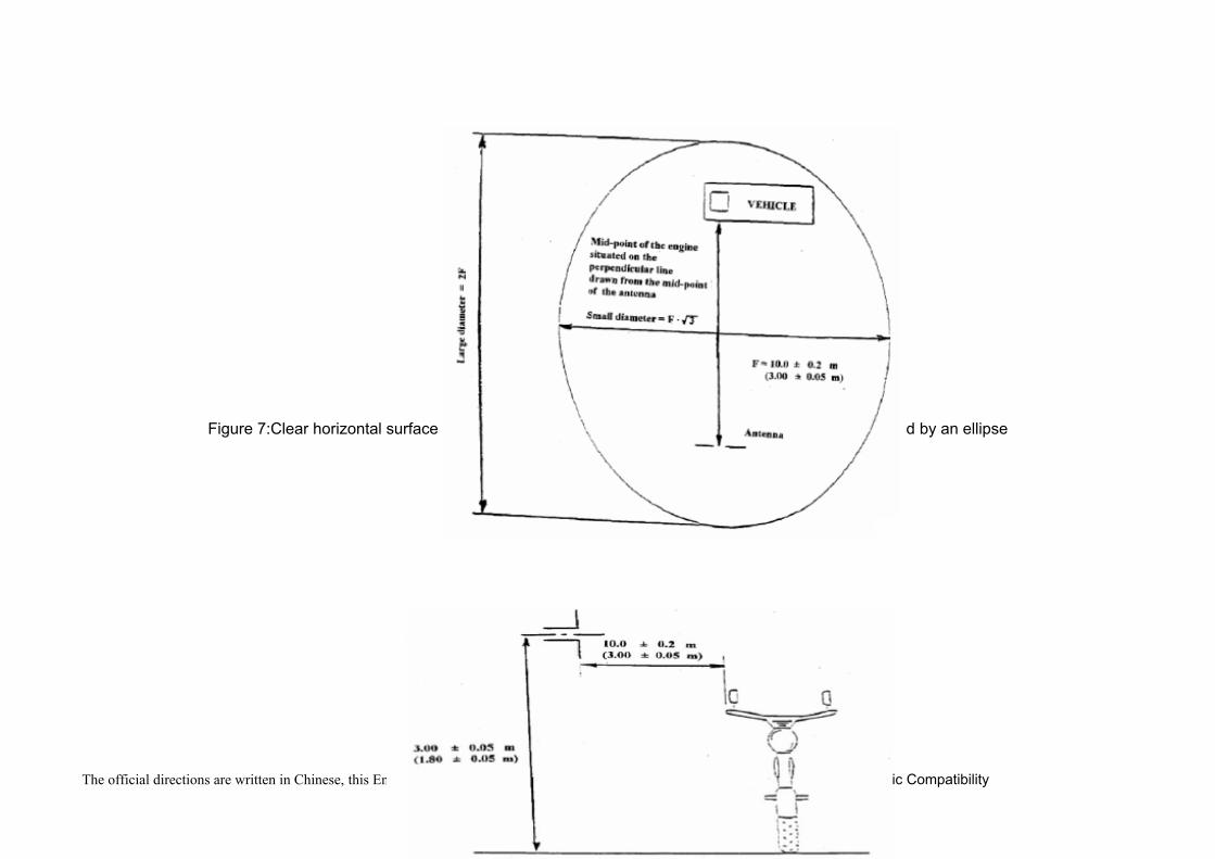
56-1.5.3 Measurement location56-1.5.3.1 As an alternative to the requirements of CISPR 12 (amendment 1, fifth edition 2005) for vehicles of category L the test
surface may be any location that fulfils the conditions shown in the figure 7. In this case the measuring equipment must lie outside the part shown in the figures 7 and 8..
56-1.5.3.2 Enclosed test facilities may be used if correlation can be shown between the results obtained in the enclosed test facility and those obtained at an outdoor site. Enclosed test facilities do not need to meet the dimensional requirements of the outdoor site other than the distance from the antenna to the vehicle and the height of the antenna.
56-1.5.4 Testing requirements56-1.5.4.1 The limits apply throughout the frequency range 30 to 1,000 MHz for measurements performed in a semi anechoic chamber
or an outdoor test site.56-1.5.4.2 Measurements can be performed with either quasi-peak or peak detectors. The limits given in paragraphs 56-1.4.2 and 56-
-13-
The official directions are written in Chinese, this English edition is for your reference only 56-1 Electromagnetic Compatibility
1.4.5 of this Regulation are for quasi-peak detectors. If peak detectors are used a correction factor of 20 dB as defined in CISPR 12 (amendment 1, fifth edition 2005) shall be applied.
56-1.5.4.3 MeasurementsThe Technical Service shall perform the test at the intervals specified in the CISPR 12 (amendment 1, fifth edition 2005) standard throughout the frequency range 30 to 1,000 MHz.Alternatively, if the manufacturer provides measurement data for the whole frequency band from a test laboratory accredited to the applicable parts of ISO 17025 (first edition 1999) and recognized by the Approval Authority, the Technical Service may divide the frequency range in 14 frequency bands 30 - 34, 34 - 45, 45 - 60, 60 - 80, 80 - 100, 100 -130, 130 - 170, 170 - 225, 225 - 300, 300-400, 400 - 525, 525 - 700, 700 - 850, 850 -1,000 MHz and perform tests at the 14 frequencies giving the highest emission levels within each band to confirm that the vehicle meets the requirements of this annex.In the event that the limit is exceeded during the test, investigations shall be made to ensure that this is due to the vehicle and not to background radiation.
56-1.5.4.4 ReadingsThe maximum of the readings relative to the limit (horizontal and vertical polarization and antenna location on the left and right-hand sides of the vehicle) in each of the 14 frequency bands shall be taken as the characteristic reading at the frequency at which themeasurements were made.
56-1.6 Method of measurement of radiated narrowband electromagnetic emissions from vehicles56-1.6.1 General
56-1.6.1.1 The test method described in this annex shall only be applied to vehicles.56-1.6.1.2 Test method
This test is intended to measure the narrowband electromagnetic emissions such as might emanate from microprocessor-based systems or other narrowband source.If not otherwise stated in this annex the test shall be performed according to CISPR 12 (amendment 1, fifth edition 2005) or to CISPR 25 (second edition 2002).
56-1.6.1.3 As an initial step the levels of emissions in the Frequency Modulation (FM) band (76 to 108 MHz) shall be measured at the vehicle broadcast radio antenna with an average detector. If the level specified in paragraph 56-1.4.3.2.4. of this Regulation is not exceeded, then the vehicle shall be deemed to comply with the requirements of this annex in respect of that frequency band and the full test shall not be carried out.
56-1.6.1.4 As an alternative for vehicles of category L the measurement location can be chosen according to paragraph 56-1.5.3.56-1.6.2 Vehicle state during tests
56-1.6.2.1 The ignition switch shall be switched on. The engine shall not be operating.56-1.6.2.2 The vehicle's electronic systems shall all be in normal operating mode with the vehicle stationary.
-14-
The official directions are written in Chinese, this English edition is for your reference only 56-1 Electromagnetic Compatibility
56-1.6.2.3 All equipment which can be switched on permanently by the driver or passenger with internal oscillators > 9 kHz or repetitive signals should be in normal operation.
56-1.6.3 Test requirements56-1.6.3.1 The limits apply throughout the frequency range 30 to 1,000 MHz for measurements performed in a semi anechoic chamber
or an outdoor test site.56-1.6.3.2 Measurements shall be performed with an average detector.56-1.6.3.3 Measurements
The Technical Service shall perform the test at the intervals specified in the CISPR 12 (amendment 1, fifth edition 2005) standard throughout the frequency range 30 to 1,000 MHz.Alternatively, if the manufacturer provides measurement data for the whole frequency band from a test laboratory accredited to the applicable parts of ISO 17025 (first edition 1999) and recognized by the Approval Authority, the Technical Service may divide the frequency range in 14 frequency bands 30 - 34, 34 - 45, 45 - 60, 60 - 80, 80 - 100, 100 - 130, 130 - 170, 170 - 225, 225 - 300, 300- 400, 400 - 525, 525 - 700, 700 - 850, 850 - 1,000 MHz and perform tests at the 14 frequencies giving the highest emission levels within each band to confirm that the vehicle meets the requirements of this annex.In the event that the limit is exceeded during the test, investigations shall be made to ensure that this is due to the vehicle and not to background radiation including broadband radiation from any ESA.
56-1.6.3.4 ReadingsThe maximum of the readings relative to the limit (horizontal and vertical polarization and antenna location on the left and right-hand sides of the vehicle) in each of the 14 frequency bands shall be taken as the characteristic reading at the frequency at which the measurements were made.
-15-
The official directions are written in Chinese, this English edition is for your reference only 56-1 Electromagnetic Compatibility
Figure 7:Clear horizontal surface free of electromagnetic reflection delimitation of the surface defined by an ellipse
-16-
The official directions are written in Chinese, this English edition is for your reference only 56-1 Electromagnetic Compatibility
Figure 8: Position of antenna in relation to the vehicle
56-1.7 Method of measurement of radiated broadband electromagnetic emissions from electrical/electronic sub-assemblies(ESAs)56-1.7.1 General
56-1.7.1.1 The test method described in this annex may be applied to ESAs, which may be subsequently fitted to vehicles, which comply with paragraph 56-1.5.
56-1.7.1.2 Test methodThis test is intended to measure broadband electromagnetic emissions from ESAs (e.g. ignition systems, electric motor,
etc.).If not otherwise stated in this annex the test shall be performed according CISPR 25 (second edition 2002).
56-1.7.2 ESA state during tests56-1.7.2.1 Test method
This test is intended to measure broadband electromagnetic emissions from ESAs (e.g. ignition systems, electric motor, etc.). If not otherwise stated in this annex the test shall be performed according CISPR 25 (second edition 2002).
56-1.7.3 Test arrangement56-1.7.3.1 The test shall be performed according to CISPR 25 (second edition 2002) clause 6.4. -ALSE method.56-1.7.3.2 Alternative measuring location
As an alternative to an absorber lined shielded enclosure (ALSE) an open area test site (OATS), which complies with the requirements of CISPR 16-1-4 (edition 1.1 2004) may be used (see appendix of this annex).
56-1.7.3.3 AmbientTo ensure that there is no extraneous noise or signal of a magnitude sufficient to affect materially the measurement,
-17-
The official directions are written in Chinese, this English edition is for your reference only 56-1 Electromagnetic Compatibility
measurements shall be taken before or after the main test. In this measurement, the extraneous noise or signal shall be at least 6 dB below the limits of interference given in paragraph 56-1.4.5.2.1 of this Regulation, except for intentional narrowband ambient transmissions.
56-1.7.4 Test requirements56-1.7.4.1 The limits apply throughout the frequency range 30 to 1,000 MHz for measurements performed in a semi anechoic chamber
or an outdoor test site.56-1.7.4.2 Measurements can be performed with either quasi-peak or peak detectors. The limits given in paragraphs 56-1.4.2 and 56-
1.4.5. of this Regulation are for quasi-peak detectors. If peak detectors are used a correction factor of 20 dB as defined in CISPR 12 (amendment 1, fifth edition 2005) shall be applied.
56-1.7.4.3 MeasurementsThe Technical Service shall perform the test at the intervals specified in the CISPR 25 (second edition 2002) standard throughout the frequency range 30 to 1,000 MHz.Alternatively, if the manufacturer provides measurement to data for the whole frequency band from a test laboratory accredited to the applicable parts of ISO 17025 (first edition 1999) and recognized by the Approval Authority, the Technical Service may divide the frequency range in 13 frequency bands 30-50, 50-75, 75-100, 100-130, 130-165, 165- 200, 200-250, 250-320, 320-400, 400-520, 520-660, 660-820, 820-1,000 MHz andperform tests at the 13 frequencies giving the highest emission levels within each band to confirm that the ESA meets the requirements of this annex.In the event that the limit is exceeded during the test, investigations shall be made to ensure that this is due to the ESA and not to background radiation.
56-1.7.4.4 ReadingsThe maximum of the readings relative to the limit (horizontal/vertical polarization) in each of the 13 frequency bands shall be taken as the characteristic reading at the frequency at which the measurements were made.
-18-
The official directions are written in Chinese, this English edition is for your reference only 56-1 Electromagnetic Compatibility
Figure 9
56-1.8 Method of measurement of radiated narrowband electromagnetic emissions from electrical /electronic sub-assemblies(ESAs).56-1.8.1 General
56-1.8.1.1 The test method described in this annex may be applied to ESAs, which may be subsequently fitted to vehicles, which comply, with paragraph 56-1.6.
56-1.8.1.2 Test methodThis test is intended to measure the narrowband electromagnetic emissions such as might emanate from a microprocessor-
based system.If not otherwise stated in this annex the test shall be performed according to CISPR 25 (second edition 2002).
56-1.8.2 ESA state during testsThe ESA under test shall be in normal operation mode.
56-1.8.3 Test arrangement56-1.8.3.1 The test shall be performed according CISPR 25 (second edition 2002) clause 6.4. -ALSE method.56-1.8.3.2 Alternative measuring location
As an alternative to an absorber lined shielded enclosure (ALSE) an open area test site (OATS) which complies with the
-19-
The official directions are written in Chinese, this English edition is for your reference only 56-1 Electromagnetic Compatibility
requirements of CISPR 16-1-4 (edition 1.1 2004) may be used (as shown in figure 9.).56-1.8.3.3 Ambient
To ensure that there is no extraneous noise or signal of a magnitude sufficient to affect materially the measurement, measurements shall be taken before or after the main test. In this measurement, the extraneous noise or signal shall be at least 6 dB below the limits of interference given in paragraph 56-1.4.6.2.1. of this Regulation, except for intentional narrowband ambient transmissions.
56-1.8.4 Test requirements56-1.8.4.1 The limits apply throughout the frequency range 30 to 1,000 MHz for measurements performed in semi anechoic chambers
or outdoor test sites.56-1.8.4.2 Measurements shall be performed with an average detector.56-1.8.4.3 Measurements
The Technical Service shall perform the test at the intervals specified in the CISPR 12 (amendment 1,5th edition 2005) standard throughout the frequency range 30 to 1,000 MHz.
56-1.8.4.4 ReadingsThe maximum of the readings relative to the limit (horizontal/vertical polarisation) in each of the 13 frequency bands shall be taken as the characteristic reading at the frequency at which the measurements were made.
56-1.9 Method of testing for immunity of vehicles to electromagnetic radiation56-1.9.1 General
56-1.9.1.1 The test method described in this paragraph shall only be applied to vehicles.56-1.9.1.2 Test method
This test is intended to demonstrate the immunity of the vehicle electronic systems. The vehicle shall be subject to electromagnetic fields as described in this paragraph. The vehicle shall be monitored during the tests.If not otherwise stated in this annex the test shall be performed according to ISO 11451-2, third edition 2005.
56-1.9.1.3 Alternative test methodsThe test may be alternatively performed in an outdoor test site for all vehicles. The test facility shall comply with (national) legal requirements regarding the emission of electromagnetic fields.If a vehicle is longer than 12 m and/or wider than 2.60 m and/or higher than 4.00 m, BCI(bulk current injection) method according to ISO 11451-4 (first edition 1995) can be used in the frequency range 20 to 2,000 MHz with levels defined in paragraph 56-1.4.7.2.1 .of this Regulation.
56-1.9.2 Vehicle state during tests56-1.9.2.1 The vehicle shall be in an unladen condition except for necessary test equipment.
56-1.9.2.1.1 The engine shall normally turn the driving wheels at a steady speed of 50 km/h if there is no technical reason due to
-20-
The official directions are written in Chinese, this English edition is for your reference only 56-1 Electromagnetic Compatibility
the vehicle to define a different condition. For vehicles of categories L1 and L2 the steady speed shall normally be turned at 25 km/h. The vehicle shall be on an appropriately loaded dynamometer or alternatively supported on insulated axle stands with minimum ground clearance if no dynamometer is available. Where appropriate, transmission shafts, belts or chains may be disconnected (e.g. trucks, two and three-wheel vehicles).
56-1.9.2.1.2 Basic vehicle conditionsThe paragraph defines minimum test conditions (as far as applicable) and failures criteria for vehicle immunity tests. Other vehicle systems, which can affect immunity related functions must be tested in a way to be agreed between manufacturer and Technical Service.
-21-
The official directions are written in Chinese, this English edition is for your reference only 56-1 Electromagnetic Compatibility
56-1.9.2.1.3 All equipment which can be switched on permanently by the driver or passenger should be in normal operation.56-1.9.2.1.4 All other systems which affect the driver's control of the vehicle shall be (on) as in normal operation of the vehicle.
56-1.9.2.2 If there are vehicle electrical/electronic systems which form an integral part of the direct control of the vehicle, which will not operate under the conditions described in paragraph 56-1.9.2.1. , it will be permissible for the manufacturer to provide a report or
-22-
The official directions are written in Chinese, this English edition is for your reference only 56-1 Electromagnetic Compatibility
additional evidence to the Technical Service that the vehicle electrical/electronic system meets the requirements of this Regulation. Such evidence shall be retained in the type approval documentation.
56-1.9.2.3 Only non-perturbing equipment shall be used while monitoring the vehicle. The vehicle exterior and the passenger compartment shall be monitored to determine whether the requirements are met (e.g. by using (a) video camera(s), a microphone, etc.).
56-1.9.3 Reference point56-1.9.3.1 For the purposes of this paragraph, the reference point is the point at which the field strength shall be established and shall
be defined as follows:56-1.9.3.2 For category M, N, O vehicles according to ISO 11451-2, third edition 2005.56-1.9.3.3 For category L vehicles:
56-1.9.3.3.1 at least 2 m horizontally from the antenna phase centre or at least 1 m vertically from the radiating elements of a transmission-line-system (TLS);
56-1.9.3.3.2 on the vehicle's centre line (plane of longitudinal symmetry);56-1.9.3.3.3 at a height of 1.0 +/- 0.05 m above the plane on which the vehicle rests or 2.0 +/- 0.05m if the minimum height of the
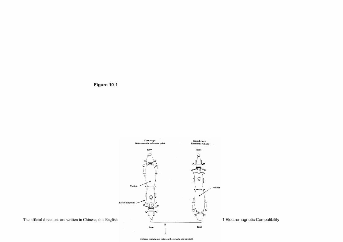
roof of any vehicle in the model range exceeds 3.0 m,56-1.9.3.3.4 At 1.0 +/- 0.2 m below the vertical centerline of the vehicle's front wheel (point C in figure 10) in the case of vehicle of
category L2 and L5. ; or at 0.2 +/- 0.2 m behind the vertical centerline of the vehicle's front wheel (point D in figure 10-1) in the case of two-wheeled vehicles.
56-1.9.3.3.5 If it is decided to radiate the rear of the vehicle, the reference point shall be established as in paragraphs 56-1.9.3.3.1. to 56-1.9.3.3.4. The vehicle shall then be installed facing away from the antenna and positioned as if it had been horizontally rotated 180 around its centre point, i.e. such that the distance from the antenna to the nearest part of the outer body of the vehicle remains the same. This is illustrated in figure 11.
-23-
The official directions are written in Chinese, this English edition is for your reference only 56-1 Electromagnetic Compatibility
Figure 10
-24-
The official directions are written in Chinese, this English edition is for your reference only 56-1 Electromagnetic Compatibility
Figure 10-1
-25-
The official directions are written in Chinese, this English edition is for your reference only 56-1 Electromagnetic Compatibility
Figure 11
56-1.9.4 Test requirements56-1.9.4.1 Frequency range, dwell times, polarization.
The vehicle shall be exposed to electromagnetic radiation in the 20 to 2,000 MHz frequency ranges in vertical polarization. The test signal modulation shall be:(a) AM (amplitude modulation), with 1 kHz modulation and 80 per cent modulation depth in the 20 to 800 MHz frequency
range, and(b) PM (pulse modulation), t on 577 microseconds, period 4,600 microseconds in the 800 to 2,000 MHz frequency range, if not otherwise agreed between Technical Service and vehicle manufacturer. Frequency step size and dwell time shall be chosen according to ISO 11451-1, third edition 2005.
56-1.9.4.1.1 The Technical Service shall perform the test at the intervals specified in ISO 11451-1,third edition 2005 throughout the frequency range 20 to 2,000 MHz.Alternatively, if the manufacturer provides measurement to data for the whole frequency band from a test laboratory accredited to the applicable parts of ISO 17025 (first edition 1999) and recognized by the Approval Authority, the Technical Service may choose a reduced number of spot frequencies in the range, e.g. 27, 45, 65, 90, 120, 150, 190, 230,280, 380, 450, 600, 750, 900, 1,300, and 1,800 MHz to confirm that the vehicle meets the requirements.If a vehicle fails the test defined in this paragraph, it must be verified as having failed under the relevant test conditions and not as a result of the generation of uncontrolled fields.
56-1.9.5 Generation of required field strength 56-1.9.5.1 Test methodology
56-1.9.5.1.1 The substitution method according to ISO 11451-1, third edition 2005 shall be used to establish the test field conditions.
56-1.9.5.1.2 CalibrationFor TLS one field probe at the facility reference point shall be used. For antennas four field probes at the facility reference line shall be used.
56-1.9.5.1.3 Test phaseThe vehicle shall be positioned with the centre line of the vehicle on the facility reference point or line. The vehicle shall normally face a fixed antenna. However, where the electronic control units and the associated wiring harness are
-26-
The official directions are written in Chinese, this English edition is for your reference only 56-1 Electromagnetic Compatibility
predominantly in the rear of the vehicle, the test should normally be carried out with the vehicle facing away from the antenna.In the case of long vehicles (i.e. excluding vehicles of categories L, M1 and N1), which have electronic control units and associated wiring harness predominantly towards the middle of the vehicle, a reference point may be established based on either the right side surface or the left side surface of the vehicle. This reference point shall be at the midpoint of the vehicle's length or at one point along the side of the vehicle chosen by the manufacturer in conjunction with the Competent Authority after considering the distribution of electronic systems and the layout of any wiring harness.Such testing may only take place if the physical construction of the chamber permits. The antenna location must be noted in the test report
56-1.10 Method(s) of testing for immunity of electrical/electronic subassemblies to electromagnetic radiation56-1.10.1 General
56-1.10.1.1The test method(s) described in this paragraph applies to ESAs.56-1.10.1.2ESAs may comply with the requirements of any combination of the following test methods at the manufacturer's discretion
provided that this results in the full frequency range specified in paragraph 56-1.10.3.1:(a) Absorber chamber test according ISO 11452-2, second edition 2004;(b) TEM cell testing according ISO 11452-3, third edition 2001;(c) Bulk current injection testing according ISO 11452-4, third edition 2005;(d) Stripline testing according ISO 11452-5, second edition 2002;
(e) 800 mm stripline according paragraph 56-1.10.4.5. of this regulation. (Frequency range and general test conditions shall be based on ISO 11452-1, third edition 2005).
56-1.10.2 State of ESA during tests56-1.10.2.1The test conditions shall be according ISO 11452-1, third edition 2005.56-1.10.2.2The ESA under test shall be switched on and must be stimulated to be in normal operation condition. It shall be arranged
as defined in this paragraph unless individual test methods dictate otherwise.56-1.10.2.3Any extraneous equipment required to operate the ESA under test shall not be in place during the calibration phase. No
extraneous equipment shall be closer than 1 m from the reference point during calibration.56-1.10.2.4To ensure reproducible measurement results are obtained when tests and measurements are repeated, the test signal
generating equipment and its layout shall be to the same specification as that used during each appropriate calibration phase.56-1.10.2.5If the ESA under test consists of more than one unit, the interconnecting cables should ideally be the wiring harnesses as
intended for use in the vehicle. If these are not available, the length between the electronic control unit and the AN shall be as defined in the standard. All cables in the wiring harness should be terminated as realistically as possible and preferably with real loads and actuators.
-27-
The official directions are written in Chinese, this English edition is for your reference only 56-1 Electromagnetic Compatibility
56-1.10.3 General test requirements56-1.10.3.1Frequency range, dwell times Measurements shall be made in the 20 to 2,000 MHz frequency range with frequency steps
according to ISO 11452-1, third edition 2005.The test signal modulation shall be:(a) AM (amplitude modulation), with 1 kHz modulation and 80 per cent modulation depth in the 20 to 800 MHz frequency range;
(b) PM (pulse modulation), t on 577 microseconds, period 4,600 microseconds in the 800 to 2,000 MHz frequency range, if not otherwise agreed between Technical Service and ESA manufacturer.Frequency step size and dwell time shall be chosen according to ISO 11452-1, third edition 2005.
56-1.10.3.2The Technical Service shall perform the test at the intervals specified in ISO 11452-1, third edition 2005 throughout the frequency range 20 to 2,000 MHz.Alternatively, if the manufacturer provides measurement to data for the whole frequency band from a test laboratory accredited to the applicable parts of ISO 17025, first edition 1999 and recognized by the Approval Authority, the Technical Service may choose a reduced number of spot frequencies in the range, e.g. 27, 45, 65, 90, 120, 150, 190, 230,280, 380, 450, 600, 750, 900, 1,300, and 1,800 MHz to confirm that the ESA meets the requirements of this paragtaph.
56-1.10.4 Special test requirements 56-1.10.4.1Absorber chamber test
56-1.10.4.1.1 Test methodThis test method allows the testing of vehicle electrical/electronic systems by exposing an ESA to electromagnetic radiation generated by an antenna.
56-1.10.4.1.2 Test methodologyThe "substitution method" shall be used to establish the test field conditions according ISO 11452-2, second edition 2004.The test shall be performed with vertical polarization.
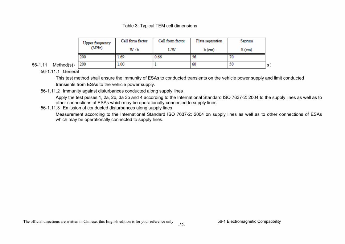
56-1.10.4.2TEM cell testing(see table 3)56-1.10.4.2.1 Test method
The TEM (transverse electromagnetic mode) cell generates homogeneous fields between the internal conductor (septum) and housing (ground plane).
56-1.10.4.2.2 Test methodologyThe test shall be performed according ISO 11452-3, third edition 2001.
Depending on the ESA to be tested the Technical Service shall chose the method of maximum field coupling to the ESA or to the wiring harness inside the TEM-cell.
56-1.10.4.3Bulk current injection testing
-28-
The official directions are written in Chinese, this English edition is for your reference only 56-1 Electromagnetic Compatibility
56-1.10.4.3.1 Test methodThis is a method of carrying out immunity tests by inducing currents directly into a wiring harness using a current injection probe.
56-1.10.4.3.2 Test methodologyThe test shall be performed according to ISO 11452-4, third edition 2005 on a test bench. As an alternative the ESA may be tested while installed in the vehicle according to ISO 11451-4 (first edition 1995) with the following characteristics:
(a) the injection probe shall be positioned in 150 mm distance to the ESA to be tested;(b) the reference method shall be used to calculate injected currents from forward power;(c) the frequency range of the method is limited by the injection probe specification.
56-1.10.4.4Stripline testing56-1.10.4.4.1 Test method
This test method consists of subjecting the wiring harness connecting the components in an ESA to specified field strengths.
56-1.10.4.4.2 Test methodologyThe test shall be performed according ISO 11452-5, second edition 2002.
56-1.10.4.5800 mm stripline testing56-1.10.4.5.1 Test method
The stripline consists of two parallel metallic plates separated by 800 mm. Equipment under test is positioned centrally between the plates and subjected to an electromagnetic field.(see figure 12, figure 13)This method can test complete electronic systems including sensors and actuators as well as the controller and wiring loom. It is suitable for apparatus whose largest dimension is less than one -third of the plate separation.
56-1.10.4.5.2 Test methodology56-1.10.4.5.2.1 Positioning of stripline
The stripline shall be housed in a screened room (to prevent external emissions) and positioned 2 m away from walls and any metallic enclosure to prevent electromagnetic reflections. RF absorber material may be used to damp these reflections. The stripline shall be placed on non-conducting supports at least 0.4 m above the floor.
56-1.10.4.5.2.2 Calibration of the striplineA field-measuring probe shall be positioned within the central one-third of the longitudinal, vertical and transverse dimensions of the space between the parallel plates with the system under test absent. The associated measuring equipment shall be sited outside the screen room. At each desired test frequency, a level of power shall be fed into the stripline to produce the required field strength at the antenna. This level of forward power, or another parameter directly related to the forward power required to define the field, shall be used for type approval tests unless changes
-29-
The official directions are written in Chinese, this English edition is for your reference only 56-1 Electromagnetic Compatibility
occur in the facilities or equipment, which necessitate this procedure being repeated.56-1.10.4.5.2.3 Installation of the ESA under test
The main control unit shall be positioned within the central one third of the longitudinal, vertical and transverse dimensions of the space between the parallel plates. It shall be supported on a stand made from non-conducting material.
56-1.10.4.5.2.4 Main wiring loom and sensor/actuator cablesThe main wiring loom and any sensor/actuator cables shall rise vertically from the control unit to the top ground plate (this helps to maximize coupling with the electromagnetic field). Then they shall follow the underside of the plate to one of its free edges where they shall loop over and follow the top of the ground plate as far as the connections to the stripline feed. The cables shall then be routed to the associated equipment, which shall be sited in an area outside the influence of the electromagnetic field, e.g.: on the floor of the screened room 1 m longitudinally away from the stripline.
-30-
The official directions are written in Chinese, this English edition is for your reference only 56-1 Electromagnetic Compatibility
Figure 12: 800 mm Stripline testing
Figure 13: 800 mm stripline dimensions
-31-
The official directions are written in Chinese, this English edition is for your reference only 56-1 Electromagnetic Compatibility
Table 3: Typical TEM cell dimensions
56-1.11 Method(s) of testing for immunity to and emission of transients of electrical/electronic sub-assembles(ESAs)56-1.11.1 General
This test method shall ensure the immunity of ESAs to conducted transients on the vehicle power supply and limit conducted transients from ESAs to the vehicle power supply.
56-1.11.2 Immunity against disturbances conducted along supply linesApply the test pulses 1, 2a, 2b, 3a 3b and 4 according to the International Standard ISO 7637-2: 2004 to the supply lines as well as to other connections of ESAs which may be operationally connected to supply lines
56-1.11.3 Emission of conducted disturbances along supply linesMeasurement according to the International Standard ISO 7637-2: 2004 on supply lines as well as to other connections of ESAs which may be operationally connected to supply lines.