5616 IEEE TRANSACTIONS ON POWER ELECTRONICS, VOL. 30, NO. 10, OCTOBER 2015
Practical Application of the Wave-Trap Conceptin Battery–Cell Equalizers
Manuel Arias, Member, IEEE, Javier Sebastian, Senior Member, IEEE, Marta M. Hernando, Senior Member, IEEE,Unai Viscarret, and Inigo Gil
Abstract—The use of battery–cell equalizers is mandatory in or-der to assure that all the cells connected in series are charged toits maximum capacity, even when they present small differences inthis parameter due to several factors, such as aging, manufactur-ing, or temperature. Active equalizers, with a higher efficiency incomparison to passive ones, have the disadvantage of using a con-siderable number of components. Moreover, in the case of activeequalizers with very high performance, this number can be evenhigher. In this paper, the use of the wave-trap concept, widely usedin telecommunication systems, is studied. This concept allows thebattery–cell equalizer to use its switching frequency as the con-trol variable that decides which cell is being charged. Hence, it isnot necessary to use a complex system based on a high numberof controlled switches in order to determine which cell is beingcharged. In this way, the number of switches (and the correspond-ing driving signals) can be strongly minimized without reducingthe performance of the system. In order to proof the validity of thisconcept (i.e., wave traps) in the design of battery–cell equalizers, atopology based on a half-bridge structure is also proposed in thispaper. It uses only two controlled switches in order to decide whichcell is charged. Experimental results are provided for a four-cellequalizer as a proof of concept.
Index Terms—Battery, balancing, cell, equalizer, frequency,wave trap.
I. INTRODUCTION
L I-ION batteries are widely used nowadays due to theirefficient charge and energy density. A battery is formed
by cells which are connected in series in order to increase itsoutput voltage and in parallel in order to increase its capacity [1].Theoretically, these cells should be all equal but, actually, theyare not, leading to differences in its capacity and its internalimpedance [2]. Their aging is also different, aggravating theproblem of their capacity mismatch over time.
Manuscript received July 8, 2014; revised September 25, 2014; acceptedNovember 10, 2014. Date of publication November 24, 2014; date of currentversion May 22, 2015. This work was supported by the Spanish Governmentunder Project CONSOLIDER MICINN-10-CSD2009-00046, Project ARROW-HEAD GA: 332987, and Project ANRI-DOC (DPI2013-47176-C2-2-R), byEuropean Union under Project SPEED (FP7-NMP3-LA-2013-604057), and byIKERLAN and ORONA under Project FUO-EM-072-13. Recommended forpublication by Associate Editor Y.-M. Chen.
M. Arias, J. Sebastian, and M. M. Hernando are with the Electronic PowerSupply Research Group, University of Oviedo, 33204 Gijon, Spain (e-mail:[email protected]; [email protected]).
U. Viscarret is with the Control Engineering and Power Eleectronics, Ikerlan,20500 Mondragon, Spain (e-mail: [email protected]).
I. Gil is with the Orona eic s.coop.Elevator Innovation Center, 20120 SanSebastian, Spain (e-mail: [email protected]).
Color versions of one or more of the figures in this paper are available onlineat http://ieeexplore.ieee.org.
Digital Object Identifier 10.1109/TPEL.2014.2373435
In a series connection of several cells (forming a cell pack),these differences in their characteristics may lead to a reductionin the maximum amount of energy that can be stored in the pack.When several Li-ion cells connected in series are charged, noneof them may be overcharged due to the risk of premature agingand irreversible deterioration. Therefore, the charging processis finished when any of the cells of the pack is fully charged,making the other cells not being fully charged and reducing theeffective overall capacity of the pack [3].
Charge equalizers are mandatory in order to assure that all thecells in a series pack are fully charged even when they presentdifferences in their capacity. In this way, the energy stored inthe battery is maximized without damaging any of the cells.Equalizers can be classified in passive and active equalizers [4],[5]. The first ones are based in dissipative methods, in which theexcess of energy is removed from fully charged cells, whilethe rest of the cells are still being charged [6], [7]. The costof this kind of equalizers is the lowest one and the controlscheme is simple. Nevertheless, the efficiency is considerablylow due to the amount of dissipated energy. Moreover, the num-ber of elements (switches and/or resistors) is not necessarilylow.
Active equalizers, on the other hand, present the highest ef-ficiency as they are based on transferring energy from one ele-ment (cell pack or most charged cell) to another element (mostdischarged cell or cell pack), until all the cells reach the fullycharged state. Actually, some energy is dissipated in the process,but its amount can be neglected in comparison to the amount ofenergy dissipated in passive equalizers. This transference canbe achieved in several ways. One option is using capacitors[7]–[13] or inductors [14]–[19] for storing the energy extractedfrom one element (e.g., the most charged cell or the cell pack)and transferring it to another element (e.g., the most dischargedcell). Another option is using converters which directly transferthe energy between cells and balance them [20]–[35]. In all thecases, the number of components is extremely high. Besides,its cost is higher than the cost of passive solutions, and in manycases its control is more complex.
Regarding the number of components, the solutions based oninductors or capacitors need a number of these reactive com-ponents similar to the number of cells connected in series [13],[17]. The number of controlled switches is also of that order. Itis possible to reduce the number of reactive components toone [10], [22], [36]. In that case, the number of controlledswitches has to be increased because the equalizer has to beable to connect the most charged cell to the reactive compo-nent, extract energy from that cell and, then, connect the same
ARIAS et al.: PRACTICAL APPLICATION OF THE WAVE-TRAP CONCEPT IN BATTERY–CELL EQUALIZERS 5617
TABLE ICOMPARATIVE OF SEVERAL BATTERY–CELL EQUALIZERS
Resistors Magnetics Capacitors1 Diodes MOSFETs Speed2 Efficiency3 Control simplicity and performance4
Dissipative [4],[6]
n 0 0 0 n L L H
Switchedcapacitors [8]
0 0 n−1 0 2 × n L M M
Single-switchedcapacitor [5],[10]
0 0 1 0 2 × (n + 1) + 4 L M L
Double-tieredswitchedcapacitors [11]
0 0 2 × n−3 0 2·n M M M
Zero-current-switchingswitchedCapacitors [13]
0 n−1 inductors n−1 0 2 × n L H M
Buck–Boost(single inductor)[14]
0 one inductor 0 2 × n 2 × n M H L
Buck–boost(multipleinductors) [15],[16]
0 n–1 inductors n 2 × (n−1) 2 × (n−1) M M M
Buck–boost(multiplecoupledinductors) [16]
0 2 × (n−1)inductors (using
n–1 cores)
n (optional) 4 × (n−1) 4 × (n−1) M M M
Selective flyback[20]
0 one transformer(one secondary
winding)
1 2 × (n−1) + 1 2 × n M M L
Multioutputflyback [21]
0 one transformer(n secondary
windings)
n n 1 H M L
Modular (mintramodules)[25]
0 m + ntransformers
0 n m + 2 × n M H L
Multiwindingtransformer [26]
0 1 transformer (nwindings) n
inductors
2 × n 0 n M H L
BidirectionalFlyback [1], [28]
0 n transformers n 0 2 × n H H M
Modular twostages (mmodules) [3]
0 m + 1transformers
1 m + 1 4 × (n−1) + (m + 1) H H L
Class-E 0 one transformer(n/2 secondary
windings)
n + 1 n 1 H H M
Proposed(wave-trapconcept)
0 n inductors (onesecondarywinding)
n n 2 M M M
L = Low; M = Medium; H = High1Smoothing capacitors are included when necessary.2Speed is evaluated according to the number of cells that can be equalized at the same time, the amount of energy transferred, the number of cells involved in the energytransmission, etc.3Efficiency is evaluated according to the number of elements that have to drive the equalizing current, the efficiency of each stage, etc.4Control includes both the precision that can be achieved in the equalization and its simplicity. It is evaluated according to the number of control signals, the easiness of generatingthem, the possibility of choosing the cell that is being charged, the necessity of sensing the voltage of all the cells, etc.
reactive component to another cell (the most discharged one). Asa consequence, the total number of components (switches plusreactive components) is not actually reduced. In the equalizersbased on converters, the total number of components (controlledswitches plus diodes plus reactive components) is also high [1],[29]. Using just one converter leads to the aforementioned prob-lem because an additional circuit based on controlled switchesneed to be implemented in order to be able to change the cellwhich is connected to the output (and in some cases, even to the
input) of the converter [3], [20]. As a consequence, the numberof controlled switches is not reduced.
In this paper, the use of the wave-trap concept [37] in battery–cell equalizers is proposed and studied. This concept is widelyused in telecommunication systems in order to build multibandantennas. The wave traps allow the antenna to disconnect partsof its elements depending on the frequency of the wave. Themain purpose of using this concept in equalizers is reducingthe number of controlled switches without losing advantages or
5618 IEEE TRANSACTIONS ON POWER ELECTRONICS, VOL. 30, NO. 10, OCTOBER 2015
reducing the performance. Also, in this paper, a topology basedon a half-bridge structure is proposed as a proof of concept. Inorder to decide which cell is going to be charged, this equalizerdoes not use a complex system with a high number of controlledswitches. The wave-trap concept is employed instead [37]. Thecell to be charged by the equalizer is determined by the switch-ing frequency of the converter and, as a consequence, the totalnumber of controlled switches is just two (those of the half-bridge structure). This also strongly reduces the complexity ofthe control scheme (e.g., there is no need of controlling a highnumber of MOSFETs referred to a floating voltage).
The switching frequency being the control variable that de-cides which cell is charged by the equalizer may imply a limitednumber of cells for a given switching frequency range, espe-cially if tolerances in the components are taken into account.As will be explained, the use of the wave-trap concept allevi-ates this problem as it allows the system to increase the numberof cells for a given switching frequency range due to the highselectivity of the traps.
The accuracy of the proposed system is high, so each cellcan be precisely charged. It should be said that it is possibleto reduce the number of controlled switches in an equalizer asproposed in [21], in which a multioutput Flyback is used. Themain drawback is that the system does not actively control thecell that is charged. It depends on the voltage of all the cellsand, also, on the leakage inductance of each output (somethingnot totally under control). As a consequence, although severalcells can be balanced at the same time, a voltage imbalance mayappear [4]. With the wave-trap concept, the leakage inductanceof the magnetic components is not a problem as the system mayactively decide which cell is charged in each moment dependingon the switching frequency of the half-bridge structure.
The purpose of this paper is analyzing the feasibility of thewave-trap concept rather than presenting a specific equalizertopology. Nevertheless, it may be interesting to include a com-parative study of different topologies including the one pro-posed in this paper as a proof of concept (it will be explained inSection III). This comparison is presented in Table I.
This paper is organized as follows. A brief description ofthe proposed concept is provided in Section II. A deep insightof the topology is given in Section III. The design guidelineresulting from the previous sections is explained in Section IV.Finally, the experimental results are shown in Section V, and theconclusions are gathered in Section VI.
II. BRIEF DESCRIPTION OF THE PROPOSED CONCEPT
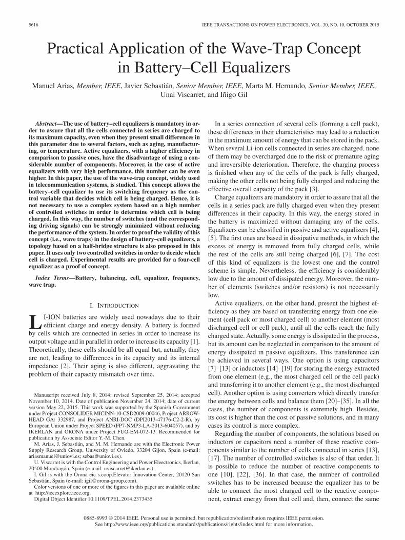
The wave-trap concept is going to be used in this applicationfor selecting the cell that is going to be charged by the proposedequalization system. In Fig. 1(a), a string of n traps is presented.Each trap consists of a capacitor and an inductor connected inparallel. Therefore, the impedance of each trap is
Zi(ω) =j · ω · Li
1 − ω2 · Li · Ci(1)
where Zi(ω) is the impedance of trap i for the pulsation ω, andLi and Ci are the inductance and the capacitance of the inductor
Fig. 1. (a) String of n traps (in gray, a sinusoidal voltage source). (b)Impedance of the n traps as a function of the frequency of the sinusoidal voltageapplied to the string.
and the capacitor used in the trap. As can be seen, each traphas one zero, which introduces a +20 dB/dec, and two poles,located at the same frequency, which lead to a –20 dB/dec slopeafter the resonant frequency fi , which is
fi =1
2 · π ·√
Li · Ci
. (2)
Each trap is designed so that its resonant frequency is dif-ferent from the resonant frequencies of the other traps [seeFig. 1(b)]. If this string of traps is supplied with a sinusoidalvoltage whose frequency is equal to the resonant frequency ofone of the traps, according to (1) its impedance will be consider-ably higher than the impedance of the other traps [see Fig. 1(b)].Consequently, nearly all the voltage applied to the string will bewithstood by this trap, while the others will only withstanda voltage close to zero due to their low impedance at thatfrequency.
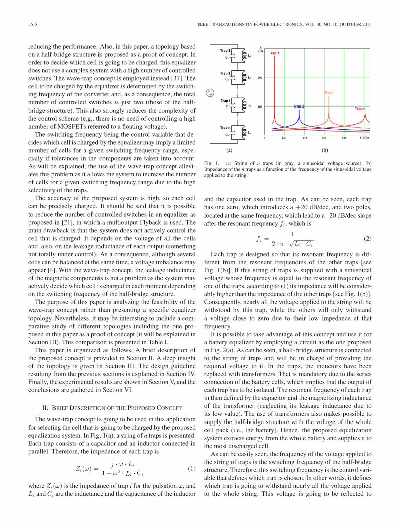
It is possible to take advantage of this concept and use it fora battery equalizer by employing a circuit as the one proposedin Fig. 2(a). As can be seen, a half-bridge structure is connectedto the string of traps and will be in charge of providing therequired voltage to it. In the traps, the inductors have beenreplaced with transformers. That is mandatory due to the seriesconnection of the battery cells, which implies that the output ofeach trap has to be isolated. The resonant frequency of each trapin then defined by the capacitor and the magnetizing inductanceof the transformer (neglecting its leakage inductance due toits low value). The use of transformers also makes possible tosupply the half-bridge structure with the voltage of the wholecell pack (i.e., the battery). Hence, the proposed equalizationsystem extracts energy from the whole battery and supplies it tothe most discharged cell.
As can be easily seen, the frequency of the voltage applied tothe string of traps is the switching frequency of the half-bridgestructure. Therefore, this switching frequency is the control vari-able that defines which trap is chosen. In other words, it defineswhich trap is going to withstand nearly all the voltage appliedto the whole string. This voltage is going to be reflected to
ARIAS et al.: PRACTICAL APPLICATION OF THE WAVE-TRAP CONCEPT IN BATTERY–CELL EQUALIZERS 5619
Fig. 2. (a) Scheme of the proposed battery equalizer. (b) Equivalent circuit.(c) Detail of trap i including the leakage and the magnetizing inductances of thetransformer.
the secondary side of the transformer and can be then used tocharge the cell connected to it. It only has to be high enoughto directly bias the rectifier diode. In fact, depending on the am-plitude of this voltage, the equalization current of the cell canbe controlled (this will be deeply explained in the next section).The other cells of the battery are not undesirably charged by theproposed system because the corresponding rectifier diodes arereverse biased due to the low value of the voltage withstood bythe corresponding traps.
III. ANALYSIS OF THE TOPOLOGY
First of all, it should be taken into account that the voltageprovided by the half-bridge structure [see VHB in Fig. 2(a)] isnot a sinusoidal waveform [as in Fig. 1(a)], but a square one.In order to have almost sinusoidal waveforms across the traps,an additional inductor LH has been included [see Fig. 2(a)].This inductor (and the traps behaving as an inductor) will with-stand the voltage harmonics above the switching frequency and,therefore, the chosen trap (i.e., the trap whose resonant fre-quency coincides with the switching frequency) will withstandan almost sinusoidal voltage. Therefore, for the sake of sim-plicity in the analysis of the topology, only the first harmoniccomponent of the voltage provided by the half-bridge structure[see VHBh1 in Fig. 2(b)] will be considered. This is a similarapproach to the one used in the analysis of resonant converters[38]–[40].
The driving scheme of the MOSFETs of the half-bridge struc-ture is the asymmetrical one [41]–[48]. The reason for choosingthis scheme (and not the more common symmetrical one) is ex-plained later in this section. In this driving scheme, the controlsignals of the MOSFETs are complementary. Hence, if D is theduty cycle of MOSFET 1, then the duty cycle of MOSFET 2is (1–D). This also means that one of them is always turnedon. As the volt–second balance in the inductive componentshas to be maintained, the voltages of the input capacitors of thehalf-bridge structure satisfy [43]
V Cin 1 = (1 − D) · Vin = (1 − D) · Vbat (3)
VCin 2 = D · Vin = D · Vbat (4)
where VC in 1 and VC in 2 are the voltages of the input capacitorsCin 1 and Cin 2 , and Vin is the input voltage of the half-bridgestructure (equal to the battery voltage Vbat). These voltagesdefine the voltage VHB(t) as can be seen in Fig. 3(a). The Fourieranalysis of this waveform leads to the following equation:
vHB hk (t) =Vin
π · k · [sin(2 · π · k · D) · cos (2 · π · fsw · k · t)
+ (1 − cos(2 · π · k · D)) · sin (2 · π · fsw · k · t)](5)
where vHB hk (t) is the kth harmonic component of the voltagevHB(t), and fsw is the switching frequency of the half-bridgestructure. Therefore, the first harmonic component satisfies
vHB h1(t) = Ah1(D,Vin ) · sin (2 · π · fsw · t + Φsw) (7)
where
Ah1(D,Vin ) =2 · Vin
π· sin(π · D) (8)
5620 IEEE TRANSACTIONS ON POWER ELECTRONICS, VOL. 30, NO. 10, OCTOBER 2015
Fig. 4. (a) Equivalent circuit of the trap. (b) Equivalent circuit when the diode is reverse biased. c) Equivalent circuit when the diode is directly biased.
Fig. 3. (a) Waveform of vHB (t) and its first harmonic component vHB h1 (t).(b) Amplitude of vHB h1 (t) for different duty cycles.
Φsw = π ·(
1 − 2 · D2
). (9)
This first harmonic component has been represented inFig. 3(a) for the depicted square-waveform voltage vHB(t).
It should be noted that the half-bridge structure will alwaysoperate with a switching frequency fsw equal to the resonantfrequency fi of one of the traps (the one connected to the mostdischarged cell)
vHB h1(t) = Ah1(D,Vin ) · sin(2 · π · fi · t + Φsw). (10)
The impedance corresponding to the nonchosen traps is verylow. The impedance of LH at any fi is also quite low. Due tothis, the voltage withstood by the chosen trap VTrap i(t) can beapproached by VHB h1(t)
vTrap i(t) ≈ vHB h1(t)= Ah1(D,Vin ) · sin(2 · π · fi · t + Φi).
(11)
Equations (8) and (11) show that the amplitude of vTrap i(t)can be controlled by means of the duty cycle D. This is thereason for using the asymmetrical driving scheme. In Fig. 3(b),the amplitude of vTrap i(t) as a function of D is represented. As
can be seen, duty cycles between 0 and 0.5 provide the samevoltage amplitude as the corresponding duty cycles in the rangebetween 0.5 and 1.0. Hence, only one of these two ranges shouldbe used. As shown in Fig. 3(b), the operating range of D will bedefined by DV min and DV max , being DV min the duty cyclewhich provides the lowest amplitude and DV max the one whichprovides the highest one. In this paper, D will be located in the0.5–1.0 range [see Fig. 3(b)].
The chosen trap shown in Fig. 2(c) has been redrawn inFig. 4(a). In this figure, the capacitor Ci has been replaced withthe voltage source vTrap i(t) due to the high-quality factor ofthe filter that each trap represents. It should be noted that thishigh-quality factor is needed for the proper operation of the pro-posed system. The behavior of the trap will change dependingon whether the diode is reverse biased or not. When it is reversebiased, the valid circuit is the one presented in Fig. 4(b). Nev-ertheless, if the voltage withstood by the trap reaches a valuehigh enough, the diode will be directly biased and the trap willbehave as the circuit presented in Fig. 4(c). Analyzing these twocircuits, it is possible to calculate the electric charge that the traptransfers to the cell in each switching period and, therefore, theamount of energy transferred. For this analysis, the followingassumptions are made:
1) The equivalent capacity of the cell is very high. Therefore,it can be considered as a constant voltage source in eachswitching period.
2) The value of the current through LH is much lower thanthe resonant current passing through the inductor and thecapacitor of the chosen trap. This is due to the aforemen-tioned high-quality factor of the traps.
3) The diode conduction time is considerably shorter thanthe resonant period. This is due to the fact that the diodewill conduct only when the voltage in the secondary sideof the transformer is positive and high enough.
4) For the sake of clarity, in the next explanation vTrap i(t)will be referred to t’, a different time reference shown inFig. 3(a). Hence, (11) can be rewritten as
vTrap i(t′) = Ah1(D,Vin ) · sin (2 · π · fi · t′) (12)
where t’ is
t′ = t +Φi
2 · π · fi. (13)
When the diode is not directly biased [see Fig. 4(b)], the cur-rent through the magnetizing inductance is equal to the currentthrough the leakage inductance. This current can be calculatedusing the sinusoidal steady-state phasor analysis because the
ARIAS et al.: PRACTICAL APPLICATION OF THE WAVE-TRAP CONCEPT IN BATTERY–CELL EQUALIZERS 5621
Fig. 5. (a) Main voltages and currents. (b) Detail of the currents between t’ch in i and t’ch end .
diode conduction time is much shorter that the resonant period(as already mentioned). Therefore
iLm i(t′) = iLk i(t′) =vTrap i(t′)
j · 2 · π · fi · Li
=1
2 · π · fi · Li· Ah1(D,Vin )
· sin(2 · π · fi · t′ −
π
2
)(14)
where
Li = LLk i + Lm i. (15)
In the same way, the current through the capacitor of the trapis
iC i(t′) = j · 2 · π · fi · Ci · vTrap i h1(t′)
= 2 · π · fi · Ci · Ah1(D,Vin ) · sin(2 · π · fi · t′ +
π
2
).
(16)
Both currents have been represented in Fig. 5(a).The diode will be directly biased when the voltage in the
secondary side of the transformer is equal to the voltage of thecell plus the knee voltage of the diode [see Fig. 4(a)]
vTrap i(t′ch ini) ·Lm i
Li· rtr i = Vcell i + Vknee (17)
where Vknee is the knee voltage of the rectifier diode, rtr i isthe turns ratio of trap i transformer (rtr i = n2/n1), and t’ch ini[see Fig. 5(a)] is the instant when the charging process of thecell starts. With (8), (12), and (17) it is possible to obtain t’ch ini
t′ch ini =1
2 · π · fi· a sin
(Vcell i + Vknee
rtr i
· Li
Lm i· π
2 · Vin · sin (π · D)
). (18)
When the diode is directly biased, the valid circuit is Fig. 4(c).Therefore, the current injected into the chosen cell is
icell i(t′) =1
rtr i(iLk i(t′) − iLm i(t′)) (19)
where
iLm i(t′) = iLm i(t′ch ini)
+1
Lm i·∫ t ′
t ′c h in i
1rtr i
· (vcell i + Vknee) · dt′
(20)
iLk i(t′) = iLk i(t′ch ini) +1
LLk i·∫ t ′
t ′c h in i
[vTrap i(t′)
− 1rtr i
· (vcell i + Vknee)]· dt′. (21)
Taking into account that iLmi(t’ch ini) = iLk i(t’ch ini), (19)
becomes
icell i(t′) =1
rtr i·[
1LLk i
·∫ t ′
t ′c h in i
[vTrap i(t′)
− 1rtr i
· (vcell i + Vknee)]· dt′
− 1Lm i
·∫ t ′
t ′c h in i
1rtr i
· (vcell i + Vknee) · dt′
].
(22)
Solving this equation yields
icell i(t′) =
Ah1(D,Vin ) · (cos (2 · π · fi · t′ch ini) − cos (2 · π · fi · t′))rtr i · LLk i · 2 · π · fi
+(Vcell i + Vknee) · (t′ch ini − t′)
r2tr i
·(
1LLk i
+1
Lm i
).
(23)
5622 IEEE TRANSACTIONS ON POWER ELECTRONICS, VOL. 30, NO. 10, OCTOBER 2015
The diode will be directly biased until the current injectedinto the cell becomes zero, at t’ch end
icell i(t′ch end) = 0. (24)
Finally, the average current injected into the chosen batterycell can be calculated very easily
Icell i = fi ·∫ t ′c h e n d
t ′c h i n i
icell i(t′) · dt′ (25)
where Icell i denotes the average value of the current injectedinto the battery cell.
The current injected into the cell should be controlled in ordernot to exceed certain levels, which would mean damaging thatbattery cell or the whole pack and, also, in order to be able toprecisely control the final voltage of the cell. As can be seen in(23), the current injected into the cell depends on the amplitudeof the first harmonic component of the voltage withstood bythe trap (Ah1(D,Vin )) and, therefore, on the duty cycle D. Asa consequence, the proposed equalizer can control the amountof energy injected into the cell during each switching period.Therefore, the system has two control variables. The first one isthe switching frequency, which defines the trap that is going tobe excited and, consequently, which cell is going to be charged.The second one is the duty cycle, which precisely defines thecurrent injected into the chosen cell.
The maximum value of the current icell i(t′), given in (23),corresponds to the maximum value of Ah1(D,Vin ), which takesplace when D = 0.5 as can be seen in (8). Therefore
icell i max(t′)
=Vin · (cos (2 · π · fi · t′ch ini) − cos(2 · π · fi · t′))
rtr i · LLk i · π2 · fi
+(Vcell i + Vknee) · (t′ch ini − t′)
r2tr i
·(
1LLk i
+1
Lm i
).
(26)
Considering this equation and (25), the maximum averagecurrent injected into the cell can be defined as
Icell i max = fi ·∫ t ′c h e n d
t ′c h i n i
icell i max(t′) · dt′. (27)
Defining Lp i as the parallel connection of LLk i and Lm i ,and λi as
λi =LLk i
Lp i=
Lm i + LLk i
Lm i(28)
(26) becomes
icell i max(t′) =1
r2tr i · 2 · π · fi · LLk i
·[2 · rtr i · Vin · (cos (2 · π · fi · t′ch ini) − cos (2 · π · fi · t′))
π
+ 2 · π · fi · λi · (Vcell i + Vknee) · (t′ch ini − t′)]. (29)
Also, defining the parameters μi , ϕi , ϕini , and ϕend as
μi =Vcell i + Vknee
Vin(30)
ϕi = 2 · π · fi · t′ (31)
ϕini = 2 · π · fi · t′ch ini (32)
ϕend = 2 · π · fi · t′ch end (33)
(29) becomes
icell i max(t′) =Vin
r2tr i · 2 · π · fi · LLk i
·[2 · rtr i · (cos ϕini − cos ϕi)
π
+ λi · μi · (ϕini − ϕi)]. (34)
This equation can be normalized by dividing icell i max(t′)by the base current Ibase i
Ibase i =Vin
2 · π · fi · LLk i(35)
obtaining
γi =icell i max(t′)
Ibase i=
1r2tr i
·[2 · rtr i · (cos ϕini − cos ϕi)
π
+ λi · μi · (ϕini − ϕi)]. (36)
From (18), (32) becomes
ϕini = a sin(
μi · λi
rtr i· π
2
). (37)
Similarly, ϕend can be obtained by making γi equal to zeroand solving
cos ϕini − cos ϕend =μi · λi
rtr i· π
2· (ϕend − ϕini). (38)
Once ϕend is obtained, the conduction angle Δϕc can beeasily obtained
Δϕc = ϕend − ϕini. (39)
The normalized maximum average current injected into thecell is [from (27)]
Γi =Icell i max
Ibase i=
12 · π ·
∫ ϕ e n d
ϕ in i
γi(ϕi) · dϕi. (40)
It should be taken into account that the magnetizing induc-tance of the transformer is considerably higher than its leakageinductance. Therefore, (28) becomes
λi ≈ 1 (41)
and hence, (18), (36), (37), and (38) become
t′ch ini ≈1
2 · π · fi· a sin
(Vcell i + Vknee
rtr i
· π
2 · Vin · sin (π · D)
)(42)
ARIAS et al.: PRACTICAL APPLICATION OF THE WAVE-TRAP CONCEPT IN BATTERY–CELL EQUALIZERS 5623
Fig. 6. Conduction angle as a function of rtr i for values of ncell around 4, which is the number of cells used in the experimental results.
γi ≈1
r2tr i
·[
2 · rtr i · (cos ϕini − cos ϕi)π
+ μi · (ϕini − ϕi)
](43)
ϕini ≈ a sin(
μi
rtr i· π
2
)(44)
cos ϕini − cos ϕend ≈ μi
rtr i· π
2· (ϕend − ϕini). (45)
For the sake of simplicity, it can be considered that the voltageof all the cells is nearly the same (i.e., Vcelli ≈ Vcell) because thevoltage imbalance is usually small in comparison to the voltageof the cells. Also, the input voltage of the half-bridge structure isthe voltage of the cell pack. Therefore, Vin ≈ Vcell · ncell , ncellbeing the number of cells connected in series. As a consequence,(30) becomes
μi =1 + νknee
ncell(46)
where νknee is
νknee =Vknee
Vcell. (47)
The evolution of the conduction angle Δϕc as a function ofthe turns ratio rtr i for different number of cells (ncell) and fordifferent values of νknee can be computed from (39), (44), thesolution of (45), and (46). Fig. 6 shows the results obtained forvalues of ncell around 4, which will be used in the Sections IV-Band V.
In the same way, Γi can be also expressed as a function ofrtr i , ncell , and νknee . The results are given in Fig. 7.
IV. DESIGN GUIDELINE
In the design of the proposed trap-based equalizer it is manda-tory to take into account several issues.
A. Influence of Tolerances
For a given trap, the nominal resonant frequency is definedby (2). For this analysis, it has been assumed that the resonantfrequency of trap i is lower than the resonant frequency of trapi + 1
fi < fi+1 . (48)
The actual resonant frequency of any trap will be inside arange defined by the tolerances of its inductor and its capacitor.Its resonant frequency may be as low as
fmin i =1
2 · π ·√
Li · (1 + tolL ) · Ci · (1 + tolC )
=fi√
(1 + tolL ) · (1 + tolC )(49)
where tolL and tolC are the tolerances of the inductor and thecapacitor of the trap. Its maximum resonant frequency due totolerances is
fmax i =1
2 · π ·√
Li · (1 − tolL ) · Ci · (1 − tolC )
=fi√
(1 − tolL ) · (1 − tolC ). (50)
5624 IEEE TRANSACTIONS ON POWER ELECTRONICS, VOL. 30, NO. 10, OCTOBER 2015
Fig. 7. Normalized maximum average current as a function of the turns ratio for values of ncell around 4.
The proposed equalizer would work properly even when theresonant frequencies of the traps were not exactly equal to thetheoretical ones as long as their relative positions were not af-fected. In other words, any trap may change its resonant fre-quency as long as it does not become lower or higher than theresonant frequency of an adjacent trap. If this condition is intro-duced in the design process, then the resulting system is robustand is not negatively affected by tolerances. The mathematicalexpression of this condition is
where τtol is defined by the tolerances of the trap components.The design should start by choosing the minimum value of
f1
fmin 1 =1
2 · π ·√
L1 · C1· 1√
(1 + tolL ) · (1 + tolC )(53)
so
L1 · C1 =1
(2 · π · fmin 1)2 · 1
(1 + tolL ) · (1 + tolC )· (54)
Once the product L1 · C1 of the first trap is obtained, it ispossible to follow an iterative process in which (52) is used tocalculate the L · C product of the next trap based on the L · Cproduct of the previous one.
B. Calculation of the Inductance, the Capacitance, and theTurns Ratio of Each Trap
There are infinite solutions for designing each trap as only thecorresponding LiCi value has been obtained in Section IV-A.Nevertheless, it is possible to optimize the design of the pro-posed equalizer considering additional conditions which willlead to specific values of the capacitance and the inductance ofeach trap.
The specific impedance Zi of each trap can be defined as
Zi =√
Li
Ci. (55)
The resonant current driven by the inductor of the chosen trapwas defined in (14). Considering this equation, (2) and (55)
iLm i(t′) = iLk i(t′) =Ah1(D,Vin )
Zi· sin
(2 · π · fi · t′ −
π
2
).
(56)
In the same way, the current driven by the capacitor [definedin (16)] is
iC i(t′) =Ah1(D,Vin )
Zi· sin
(2 · π · fi · t′ +
π
2
). (57)
Considering D = 0.5, (56) and (57) becomes
iLm i max(t′) = iLk i max(t′)
=2 · Vin
Zi · π· sin
(2 · π · fi · t′ −
π
2
)(58)
iC i max(t′) =2 · Vin
Zi · π· sin
(2 · π · fi · t′ +
π
2
). (59)
The ratio between the energy in the resonant circuit (i.e.,chosen trap) and the energy injected into the chosen cell during
ARIAS et al.: PRACTICAL APPLICATION OF THE WAVE-TRAP CONCEPT IN BATTERY–CELL EQUALIZERS 5625
Fig. 8. Trap voltage and cell current for different values of QE i . The distortion in the trap voltage depends on this parameter.
each switching period is denoted by QE i , and can be definedas
QE i =Eres i
Ecell i(60)
where Eres i is the energy in the resonant circuit, and Ecell i isthe energy injected into the cell. If the amount of energy injectedinto the cell is lower than the amount of resonant energy thatthe chosen trap is handling, then the behavior of the string oftraps will not depend on whether the diode is reverse biased ornot. This means that the voltage across the capacitor of the trapwill be sinusoidal even during the short periods of time when thediode is conducting. Hence, it is interesting to design the systemwith values of QE i higher than unity so that the behavior of thetrap is not affected by the cell (see later in this section).
The resonant energy in the chosen trap can be obtained fromits voltage and the value of its capacitor (when the voltage inthe trap is the peak one, the energy in the inductor is zero)
Eres i = Ci ·2 · V 2
in
π2 . (61)
The energy injected into the cell in each switching period canbe denoted as
Ecell i =Icell i max · Vcell i
fi. (62)
Hence
QE i =2 · fi · Ci · V 2
in
π2 · Vcell i · Icell i max. (63)
Taking into account (2) and (55), then (63) becomes
QE i =V 2
in
π3 · Zi · Vcell i · Icell i max. (64)
Fig. 8 shows the waveforms corresponding to the voltageacross the resonant capacitors and the current injected into thecells obtained for different values of QE i . As Fig. 8 shows, thevoltage across the capacitor can be considered sinusoidal whenthe value of QE i is higher than two. However, very high valuesof QE i lead to high circulating currents through the resonantcapacitor and inductor, as can be deduced from (58), (59), and(64). As a consequence, a tradeoff must be met when choosingthe values of QE i in order to obtain a system in which efficiencyis not excessively affected, while the voltage across the resonantcapacitor can be considered sinusoidal even when the diode is
Fig. 9. Design flowchart.
directly biased. Values of QE i around two (or slightly higher)can be considered good options. In fact, QE i can be designedto be lower than two [as in Fig. 8(a) or (b)]. Nevertheless, insuch a case, the voltage is excessively distorted and the behaviorof the system cannot be predicted by the proposed equations.
With (28), (40), (46), and (47) (64) can be rewritten as
QE i =1π2 · λi − 1
λi· 1(μi − νknee) · Γi
(65)
which will be used in the design guideline.The calculation of the precise values of Li and Ci should be
made as follows (see Fig. 9). First of all, the value of νknee canbe calculated using (47). With νknee and the number of cellsncell the value of μi can be then obtained from (46). Choosinga reasonable value for the conduction angle Δϕc (i.e., around30°), and with μi , it is possible to obtain the value of the turnsratio of the transformers rtr i by means of (39), (44), and (45).In Fig. 6, (39) is graphically represented, the conduction angleis depicted as a function of rtr i for different values of ncell
5626 IEEE TRANSACTIONS ON POWER ELECTRONICS, VOL. 30, NO. 10, OCTOBER 2015
and νknee (both define the value of μi). Equation (44), alongwith rtr i and μi , can be used to obtain the value of ϕini and,consequently, the value of ϕend according to the chosen value ofΔϕc . Γi can be calculated using ϕini , ϕend , rtr i , μi , and (40)and (43). This has been graphically represented in Fig. 7. Ashas been explained, the value of QE i should be high enoughin order to assure the proper operation of the resonant traps(as can be seen in Fig. 8, any value of QE i higher than 2will lead to satisfactory results). Therefore, once Γi is obtained,(65) can be used to determine the minimum value of λi for thechosen value of QE i . This minimum value of λi [see (28)],should be lower than the value of λi presented by any of thetransformers of the traps once they are built. Icell i max , themaximum average equalizing current, is a parameter defined bythe designer. Therefore, if the value of λi is satisfactory (i.e.,low enough), then (64) can be used to obtained the value of Zi
according to the chosen value of QE i . With Zi [(55)] and fi
(its calculation was presented in Section IV-A), it is possible toobtain the required values of Li and Ci .
C. Design of the Magnetics
The switching frequency of the proposed system is variable,but ideally, each inductor is going to withstand appreciable volt-age only at a frequency equal to the resonant frequency of thetrap it belongs to. When the switching frequency of the systemis different from the resonant frequency of a trap, the voltageacross that trap is almost zero and, consequently, its inductorcurrent is almost zero as well. This means that each inductordoes not have to be designed for the whole frequency range,but only for the resonant frequency of its trap [36]. Hence, itsdesign can be optimized and tuned for that frequency, reducingits losses and optimizing the overall design.
Regarding the design parameters, the maximum current,needed for designing a saturation-free transformer, and the accurrent, needed for calculating the core losses, can be obtainedfrom the equations presented in Section III. The rms currentthrough primary and secondary side of the transformer, neededto calculate the conduction losses, can be obtained also fromSection III. Finally, the required inductance and the turns ratiohave been obtained in Section IV-B.
V. EXPERIMENTAL RESULTS
A prototype has been built following the design guidelineand with the purpose of validating the proposed topology. It hasbeen designed for a pack of four cells connected in series. Theswitching frequency range is 100–215 kHz considering toler-ances of 7.5% in both, inductors and capacitors (see Table II).The value of each resonant frequency fi has been obtained ac-cording to the design process described in Section IV-A. Thevalue of νknee is around 0.2; therefore, μi is 0.3. As can be seenin Fig. 6, for a conduction angle of around 30°, the required turnsratio is 0.48. It may advisable to increase this value so that evendue to tolerances, the RDSON of the MOSFETs, the influenceof other traps, etc., the required voltage in the secondary side ofthe transformer is reached. From Fig. 7 (or the correspondingequations), the resulting value of Γi is around 2 × 10⁻³. As
TABLE IIMINIMUM, NOMINAL, AND MAXIMUM RESONANT FREQUENCY OF EACH TRAP.
NOMINAL VALUES OF INDUCTANCE AND CAPACITANCE
TRAP fn o m (kHz) fm in (kHz) fm a x (kHz) L (μH) C (μF)
Fig. 10. Frequency sweep of the string of traps (including the additionalinductor LH ).
a consequence, the required minimum value of λi is 1.009 forQE i = 5 (higher than 2, the minimum value shown in Fig. 8).This value of λi is lower than the real value that any transformernormally has. Therefore, it is a valid design regarding this issue.Icell i max is defined according to the requirements of the sys-tem and its value is 0.1 A. Consequently, the value of Zi shouldbe close to 4. With Zi and fi , it is possible to obtain the valuesof Li and Ci (see Table II).
In Fig. 10, the impedance and phase of the string of trapsimplemented in the prototype are presented. As can be seen, ateach resonant frequency, the overall impedance is defined bythe impedance of the trap. Therefore, nearly all the voltage willbe withstood by that trap. Harmonic components higher thanthe first one will be withstood by the traps with a resonant fre-quency higher than the chosen one and, mainly, by the additionalinductor LH .
In Fig. 11, the gate signals of the MOSFETs are presented. Ascan be seen, they are complementary and can be easily obtained,which make the control scheme very simple. The voltages ofCin 1 and Cin 2 change according to the duty cycle. This varia-tion is the reason why the asymmetrical driving scheme allowsthe system to control the amplitude of the first harmonic compo-nent of the square voltage provided to the string of traps by thehalf-bridge structure. It should be mentioned that having onlytwo driving signal implies that the control of the system can be
ARIAS et al.: PRACTICAL APPLICATION OF THE WAVE-TRAP CONCEPT IN BATTERY–CELL EQUALIZERS 5627
Fig. 11. Driving signals of both MOSFETs and voltage of the two input capacitors when (a) D = 50%, (b) D = 75%, and (c) D = 90%.
Fig. 12. Driving signal of MOSFET 1, string voltage and trap 3 voltage for (a) D = 50%, (b) D = 75% and (c) D = 90%.
easily implemented. The voltage of each cell can be measuredusing monitoring ICs (such as the LTC6802 or the BQ76PL536)and sent to the controller via serial communication. With thosevoltages, it can decide which cell should be charged by theequalizer. Then, it only has to generate the two driving signalswith the desired switching frequency. When a new cell has to becharged, the system only has to change the switching frequencyof the two MOSFETs. In the case of reaching the equalization,the driving signals of both MOSFETs are driven low in order tostop the operation of the converter. It should be also mentionedthat the system does not need to sense and control the switchingfrequency with a feedback loop. The precision obtained withthe PWM module of any microcontroller (or with any FPGA)is enough to assure that the switching frequency is within therequired tolerances for the proper operation of the system.
In Fig. 12, Vstring the voltage withstood by string of traps,and Vtrap 3 the voltage withstood by the chosen trap (in thiscase, trap 3) are shown for three different values of D but forthe same value of switching frequency (166 kHz in order tochoose trap 3). As can be seen, the proposed system can de-termine the amplitude of the voltage withstood by the chosentrap by means of the duty cycle. This implies that the charg-ing process (final voltage of the cell, equalization current, etc.)can be perfectly controlled. Moreover, the negative effects ofthe leakage inductance or the knee voltage can be overcome.Equalizers based on filters usually use the frequency not onlyfor choosing the cell, but also for controlling the charging pro-cess by introducing small variations in this control variable (likein the LLC resonant converter). In the proposed system, the con-
trol variable that defines the chosen trap (i.e., the frequency) isdifferent from the control variable that defines the charging pro-cess (i.e., the duty cycle). This leads to a higher performance andaccuracy.
In Fig. 13, the voltage of the four traps is presented for thefour possible switching frequencies (i.e., resonant frequencies).As can be seen, the switching frequency perfectly defines whichcell is going to be charged by the proposed system. The trapwhose resonant frequency is equal to the switching frequencyof the half-bridge structure withstands nearly all the first har-monic component, while the other traps withstand a voltageclose to zero. Therefore, the switching frequency represents avalid control variable. As can be seen in Fig. 13(b) and (c), thevoltage of the traps which have not be chosen presents a relativephase lag of 180° due to the inductive behavior of the traps witha resonant frequency higher than the switching frequency andthe capacitive behavior of the traps whose resonant frequencyis lower than the selected switching frequency. In Fig. 13(a)and (d), the voltages of all the nonchosen traps are in phasebecause they all have the same behavior (inductive in the caseof Fig. 13(a) and capacitive in the case of Fig. 13(d)].
In Fig. 14, the secondary-side voltage of the transformer im-plemented in trap 3 (Vsec 3), the voltage of cell 3 (Vcell 3),the equalization current of this cell during a switching period(Icell 3), and the voltage applied to trap 3 (Vtrap 3rtr , referred tothe secondary side) are presented for three different duty cycles.As can be seen, the charging process is as described in SectionIII. When Vsec 3 is equal to the voltage of the cell plus the kneevoltage of the rectifier diode, this diode is directly biased and
5628 IEEE TRANSACTIONS ON POWER ELECTRONICS, VOL. 30, NO. 10, OCTOBER 2015
Fig. 13. Voltage of the four traps when the switching frequency is equal to the resonant frequency of (a) trap 1, (b) trap 2, (c) trap 3, and (d) trap 4. In all thecases D = 50%.
Fig. 14. Equalization current, cell 3 voltage, and trap 3 voltage for three different charging rates. (a) D = 50%. (b) D = 75%. c) D = 90%.
part of the energy stored in the reactive elements of trap 3 istransferred to the cell, which leads to the current waveform (i.e.,resonant current) presented in the figure. This current keepsthe diode directly biased even when the voltage in the trap (re-flected to the secondary side) is lower than the voltage of the cellplus the knee voltage of the diode. When this current naturallyreaches zero (t’ch end ), the diode is reverse biased. Therefore,the diode is operating at zero-current switching.
The purpose of this paper is analyzing the feasibility of thewave-trap concept rather than presenting the equalizer based onthe asymmetrical half-bridge converter, which was used only asa proof of concept. As can be seen in Table I, the wave-trapconcept satisfies the purpose of developing equalizers with areduced number of controlled switches. It should be mentionedthat this reduction does not imply losing performance becausethe charging process is totally under control and it does not
ARIAS et al.: PRACTICAL APPLICATION OF THE WAVE-TRAP CONCEPT IN BATTERY–CELL EQUALIZERS 5629
Fig. 15. (a) Evolution of the voltages of cells 3 and 4 when they are represented by 1000-μF capacitors. (b) Measured cell voltage during discharging. (c)Operation of the proposed battery–cell equalizer with different starting voltages for each cell around their nominal value. (d) Operation of the proposed battery–cellequalizer when one of the cells has reached the maximum value. (e) Detail of the charging process of one of the cells.
imply either increasing the number of other components (i.e.,the total number of component is similar to other topologieswith the same high performance).
In Fig. 15(a), the voltages of cells 3 and 4 are shown. Forobtaining this figure, capacitors of 1000 μF are used instead ofreal battery cells (in Fig. 15(c)–(e), real lithium-ion battery cellsare used). In this way, it is possible to verify the results in ashorter time and, moreover, the system faces battery cells witha lower capacity, which involves that more precision is requiredin order not to exceed the desired voltage. In this case, it can beseen that cell 3 has a voltage of 2.0 V, lower than the voltage ofthe other cells (around 4.2 V). The proposed equalizer injectsenergy into cell 3 and raises its voltage to a value close to thevoltage of the other cells.
In Fig. 15(c)–(e), the proposed equalizer is connected to real2.5-Ah lithium-ion battery cells. In Fig. 15(b), their dischargecharacteristic, obtained through experimental verification, isprovided.
In Fig. 15(c), the operation of the proposed equalizer is pre-sented when the voltage of each cell is close to their nominalvalue (around 3.3 V). At the beginning, the lowest voltage cor-responds to cell 3. The control of the equalizer sets the switch-ing frequency of the half-bridge converter in 164 kHz. After32 min, the voltage of cell 3 has reached the value of cell 2and, therefore, the system changes the switching frequency to200 kHz, in order to charge cell 4. After 46 min, the voltageof cell 4 becomes the highest value, and the system changes
the frequency to 164 kHz during 14 min in order to chargecell 3. After 92 min, the voltage of the four cells is within thedesired range and the half-bridge converter stops its operation(i.e., both MOSFETs are turned-off). After 150 min from thestart of the equalization process, the voltage of the four cells isstabilized and the final imbalance is around 5 mV. It should betaken into account that using a simple estimation of the OCVof the cells as the criterion for defining which one has to becharged is not an optimum approach. More precise methods canbe found in the literature [49]–[51]. These methods take intoaccount the influence of temperature, uncertainties in models,mapping nonlinearity, aging, etc., and are based on inverse map-ping, Coulomb counting or extended Kalman filtering. Never-theless, the implementation of an optimum battery managementsystem (BMS) is out of the scope of this paper and, as a con-sequence, the simplest approach to the BMS development waschosen.
In Fig. 15(d) a similar test is carried out, but in this case oneof the cells has reached 3.6 V (i.e., the recommended chargingvoltage), while cells 2, 3, and 4 have a lower voltage (unbalancedoperation of the battery charger). As in the previous case, thecell with the lowest voltage is considered undercharged. Due tothe region in which battery cells are operated, the equalizationprocess is faster (23 min) and the final imbalance, after thestabilization time (around 50 min), is close to 10 mV. Finally,in Fig. 15(e), a detail of the charging process of one of the cellsis presented (the stabilization time is not shown).
5630 IEEE TRANSACTIONS ON POWER ELECTRONICS, VOL. 30, NO. 10, OCTOBER 2015
VI. CONCLUSION
The wave-trap concept has proven to be a valid option forbattery–cell equalizers. The switching frequency can be effec-tively used as the control variable that defines the cell that isgoing to be charged and, as a consequence, the number of con-trolled switches in the topology can be reduced. The duty cyclecan be used as a different control variable in order to regulatethe charging process of the chosen cell. This control variablealso allows the system to ignore the influence of certain param-eters, such as the leakage inductance or the knee voltage of therectifier diode, which cannot be totally defined in the designprocess and may affect the operation of the system. Hence, anyequalizer based on the wave-trap concept can be considered asa high-performance one. The ratio between the resonant energyand the energy transferred to the cell should be carefully chosenduring the design process in order not to excessively affect theefficiency of the equalizer.
The equalizer presented as a proof of the proposed conceptis based on a half-bridge structure, so its number of controlledswitches is only two. The number of cells that can be controlledby an equalizer based on this concept is limited by the maximumfrequency range. Nevertheless, the use of traps, which have avery high selectivity, increases the number of cells for that givenrange. For instance, the proposed topology allocates four trapsin a frequency range of 100 kHz considering tolerances of up to7.5% in the components. Any equalizer based on this conceptis also highly modular, so the number of cells can be increasedwithout enlarging the frequency range. In that case, the numberof controlled switches is increased according to the number ofmodules connected, but it will always be considerably lowerthan the number of cells. The use of traps, rather than filtersconnected to the output of the converter, allows the magneticcomponents to have an optimized design. Each inductor operatesonly at the resonant frequency of the trap it belongs to becausefor the other frequencies its voltage and its current are closeto zero. Therefore, their design can be optimized only for onefrequency and, as a consequence, size and losses can be stronglyreduced.
Finally, the analysis based on the first harmonic componenthas proven to be perfectly valid as it simplifies the calculationand design guideline of the equalizer, while keeping accurateenough results. This has been validated by means of experimen-tal results.
REFERENCES
[1] L. M. Einhorn, W. Guertlschmid, T. Blochberger, R. Kumpusch, R. Per-mann, F. V. Conte, C. Kral, and J. Fleig, “A current equalization methodfor serially connected battery cells using a single power converter for eachcell,” IEEE Trans. Veh. Technol., vol. 60, no. 9, pp. 4227–4237, Nov. 2011.
[2] M. Einhorn, F. V. Conte, C. Kral, and J. Fleig, “Comparison, selection, andparameterization of electrical battery models for automotive applications,”IEEE Trans. Power Electron., vol. 28, no. 3, pp. 1429–1437, Mar. 2013.
[3] K. Chol-Ho, K. Moon-young, P. Hong-sun, and M. Gun-Woo, “A modu-larized two-stage charge equalizer with cell selection switches for series-connected lithium-ion battery string in an HEV,” IEEE Trans. PowerElectron., vol. 27, no. 8, pp. 3764–3774, Aug. 2012.
[4] M. Daowd, N. Omar, P. Van Den Bossche, and J. Van Mierlo, “Passiveand active battery balancing comparison based on MATLAB simulation,”in Proc. IEEE Veh. Power Propulsion Conf., 2011, pp. 1–7.
[5] J. Cao, N. Schofield, and A. Emadi, “Battery balancing methods: Acomprehensive review,” in Proc. IEEE Veh. Power Propul. Conf., 2008,pp. 1–6.
[6] T. A. Stuart and Z. Wei, “Fast equalization for large lithium ion batteries,”IEEE Aerosp. Electron. Syst. Mag., vol. 24, no. 7, pp. 27–31, Jul. 2009.
[7] V. L. Teofilo, L. V. Merritt, and R. P. Hollandsworth, “Advanced lithiumion battery charger,” IEEE Aerosp. Electron. Syst. Mag., vol. 12, no. 11,pp. 30–36, Nov. 1997.
[8] C. Pascual and P. T. Krein, “Switched capacitor system for automaticseries battery equalization,” in Proc. 12th Annu. Appl. Power Electron.Conf. Expo., 1997, vol. 2, pp. 848–854.
[9] J. M. Henry and J. W. Kimball, “Practical performance analysis of complexswitched-capacitor converters,” IEEE Trans. Power Electron., vol. 26,no. 1, pp. 127–136, Jan. 2011.
[10] C. Speltino, A. Stefanopoulou, and G. Fiengo, “Cell equalization in batterystacks through state of charge estimation polling,” in Proc. Amer. ControlConf., 2010, pp. 5050–5055.
[11] A. C. Baughman and M. Ferdowsi, “Double-tiered switched-capacitorbattery charge equalization technique,” IEEE Trans. Ind. Electron.,vol. 55, no. 6, pp. 2277–2285, Jun. 2008.
[12] K. Sano and H. Fujita, “A resonant switched-capacitor converter for volt-age balancing of series-connected capacitors,” in Proc. Int. Conf. PowerElectron. Drive Syst., 2009, pp. 683–688.
[13] Y. Ye, K. W. E. Cheng, and Y. P. B. Yeung, “Zero-current switch-ing switched-capacitor zero-voltage-gap automatic equalization systemfor series battery string,” IEEE Trans. Power Electron., vol. 27, no. 7,pp. 3234–3242, Jul. 2012.
[14] P. Sang-Hyun, K. Tae-Sung, P. Jin-Sik, M. Gun-Woo, and Y. Myung-Joong, “A new buck-boost type battery equalizer,” in Proc. IEEE 24thAnnu. Appl. Power Electron. Conf. Expo., 2009, pp. 1246–1250.
[15] K. Nishijima, H. Sakamoto, and K. Harada, “A PWM controlled simpleand high performance battery balancing system,” in Proc. IEEE 31st Annu.Power Electron. Spec. Conf., 2000, vol. 1, pp. 517–520.
[16] P. Thanh Hai, J. C. Crebier, A. Chureau, A. Collet, and T. Van Nguyen,“Optimized structure for next-to-next balancing of series-connectedlithium-ion cells,” in Proc. IEEE 26th Annu. Appl. Power Electron. Conf.Expo., 2011, pp. 1374–1381.
[17] M. J. Isaacson, R. P. Hollandsworth, P. J. Giampaoli, F. A. Linkowsky,A. Salim, and V. L. Teofilo, “Advanced lithium ion battery charger,” inProc. 15th Annu. Battery Conf. Appl. Adv., 2000, pp. 193–198.
[18] P. A. Cassani and S. S. Williamson, “Design, testing, and validation ofa simplified control scheme for a novel plug-in hybrid electric vehi-cle battery cell equalizer,” IEEE Trans. Ind. Electron., vol. 57, no. 12,pp. 3956–3962, Dec. 2010.
[19] K. Tae-Hoon, P. Nam-Ju, K. Rae-Young, and H. Dong-Seok, “Low costmultiple zero voltage/zero current switching battery equalization circuitwith single soft-switching resonant cell,” in Proc. IEEE Veh. Power Propul.Conf., 2012, pp. 419–424.
[20] S. Jong-Won, S. Gab-Su, C. Chang-Yoon, and C. Bo-Hyung, “Selectiveflyback balancing circuit with improved balancing speed for series con-nected Lithium-ion batteries,” in Proc. Int. Power Electron. Conf., 2010,pp. 1180–1184.
[21] N. H. Kutkut, H. L. N. Wiegman, D. M. Divan, and D. W. Novotny,“Design considerations for charge equalization of an electric vehicle bat-tery system,” IEEE Trans. Ind. Appl., vol. 35, no. 1, pp. 28–35, Jan./Feb.1999.
[22] P. Sang-Hyun, P. Ki-Bum, K. Hyoung-Suk, M. Gun-Woo, and Y. Myung-Joong, “Single-magnetic cell-to-cell charge equalization converter withreduced number of transformer windings,” IEEE Trans. Power Electron.,vol. 27, no. 6, pp. 2900–2911, Jun. 2012.
[23] N. H. Kutkut, D. M. Divan, and D. W. Novotny, “Charge equalizationfor series connected battery strings,” in Proc. IEEE Ind. Appl. Soc. Annu.Meet., Conf. Rec, 1994, vol. 2, pp. 1008–1015.
[24] Y. C. Hsieh, J. L. Wu, and X. H. Chen, “Class-E-based charge-equalisationcircuit for battery cells,” Power Electron., IET, vol. 5, pp. 978–983,2012.
[25] P. Hong-sun, K. Chong-Eun, K. Chol-Ho, M. Gun-Woo, and L. Joong-Hui, “A modularized charge equalizer for an HEV lithium-ion batterystring,” IEEE Trans. Ind. Electron., vol. 56, no. 5, pp. 1464–1476,May 2009.
[26] L. Siqi, C. C. Mi, and Z. Mengyang, “A high-efficiency active battery-balancing circuit using multiwinding transformer,” IEEE Trans. Ind. Appl.,vol. 49, no. 1, pp. 198–207, Jan./Feb. 2013.
[27] M. Einhorn, W. Roessler, and J. Fleig, “Improved performance of se-rially connected Li-ion batteries with active cell balancing in electricvehicles,” IEEE Trans. Veh. Technol., vol. 60, no. 6, pp. 2448–2457, Jul.2011.
ARIAS et al.: PRACTICAL APPLICATION OF THE WAVE-TRAP CONCEPT IN BATTERY–CELL EQUALIZERS 5631
[28] C. Karnjanapiboon, K. Jirasereeamornkul, and V. Monyakul, “High effi-ciency battery management system for serially connected battery string,”in Proc. IEEE Int. Symp. Ind. Electron., 2009, pp. 1504–1509.
[29] K. Chol-Ho, K. Moon-Young, and M. Gun-Woo, “A modularized chargeequalizer using a battery monitoring IC for series-connected Li-ion batterystrings in electric vehicles,” IEEE Trans. Power Electron., vol. 28, no. 8,pp. 3779–3787, Aug. 2013.
[30] Y.-S. Lee and C. Ming-Wang, “Intelligent control battery equalization forseries connected lithium-ion battery strings,” IEEE Trans. Ind. Electron.,vol. 52, no. 5, pp. 1297–1307, Oct. 2005.
[31] M. Uno and K. Tanaka, “Single-switch cell voltage equalizer using mul-tistacked buck-boost converters operating in discontinuous conductionmode for series-connected energy storage cells,” IEEE Trans. Veh. Tech-nol., vol. 60, no. 8, pp. 3635–3645, Oct. 2011.
[32] W. Xuezhe and Z. Bing, “The research of vehicle power Li-ion batterypack balancing method,” in Proc. 9th Int. Conf. Electron. Meas. Instrum.Conf., 2009, pp. 2–498-2–502.
[33] A. M. Imtiaz, F. H. Khan, and H. Kamath, “A low-cost time shared cellbalancing technique for future lithium-ion battery storage system featuringregenerative energy distribution,” in Proc. IEEE 26th Annu. Appl. PowerElectron. Conf. Exp., 2011, pp. 792–799.
[34] F. Baronti, G. Fantechi, R. Roncella, and R. Saletti, “High-efficiencydigitally controlled charge equalizer for series-connected cells based onswitching converter and super-capacitor,” IEEE Trans. Ind. Informat.,vol. 9, no. 2, pp. 1139–1147, May 2013.
[35] H. Yi-Hsun, L. Tsorng-Juu, S. M. O. Chen, H. Wan-Yi, and C. Yi-Yuan, “Anovel high-efficiency compact-size low-cost balancing method for series-connected battery applications,” IEEE Trans. Power Electron., vol. 28, no.12, pp. 5927–5939, Dec. 2013.
[36] J.-W. Kim, J.-W. Shin, and J.-I. Ha, “Cell balancing control using adjustedfilters in flyback converter with single switch,” in Proc. IEEE EnergyConvers. Congr. Expo., Sep. 2013, vol. 287, no. 291, pp. 15–19.
[37] L. Low, J. Batchelor, R. Heaton, and N. Chen, “Dual patches microstrip fedantenna with wide bandwidth,” in Proc. Loughborough Antennas Propag.Conf., Nov. 2009, vol. 429, no. 432, pp. 16–17.
[38] F. Weiyi, F. C. Lee, P. Mattavelli, and H. Daocheng, “A universal adaptivedriving scheme for synchronous rectification in LLC resonant converters,”IEEE Trans. Power Electron., vol. 27, no. 8, pp. 3775–3781, Aug. 2012.
[39] F. Dianbo, L. Ya, F. C. Lee, and X. Ming, “A novel driving scheme forsynchronous rectifiers in LLC resonant converters,” IEEE Trans. PowerElectron., vol. 24, no. 5, pp. 1321–1329, May 2009.
[40] M. K. Kazimierczuk and W. Szaraniec, “Analysis of class E low di/dtrectifier with a series inductor,” IEEE Trans. Aerosp. Electron. Syst.,vol. 29, no. 1, pp. 278–287, Jan. 1993.
[41] M. Arias, D. G. Lamar, F. F. Linera, D. Balocco, A. A. Diallo, and J.Sebastian, “Design of a soft-switching asymmetrical half-bridge structureas second stage of an LED driver for street lighting application,” IEEETrans. Power Electron., vol. 27, no. 3, pp. 1608–1621, Mar. 2012.
[42] G. Y. Jeong, “High efficiency asymmetrical half-bridge structure using aself-driven synchronous rectifier,” Power Electron., IET, vol. 1, pp. 62–71,2008.
[43] R. Oruganti, H. Phua Chee, J. T. K. Guan, and C. Liew Ah, “Soft-switchedDC/DC converter with PWM control,” IEEE Trans. Power Electron.,vol. 13, no. 1, pp. 102–114, Jan. 1998.
[44] M. Arias, F. Diaz, D. G. Lamar, D. Balocco, A. A. Diallo, and J. Se-bastian, “High-efficiency asymmetrical half-bridge structure without elec-trolytic capacitor for low-output-voltage AC-DC LED drivers,” IEEETrans. Power Electron., vol. 28, no. 5, pp. 2539–2550, May 2013.
[45] L. Bor-Ren, Y. Cheng-Chang, and D. Wang, “Analysis, design and imple-mentation of an asymmetrical half-bridge structure,” in Proc. IEEE Int.Conf. Ind. Technol., 2005, pp. 1209–1214.
[46] P. K. Jain, A. St-Martin, and G. Edwards, “Asymmetrical pulse-width-modulated resonant DC/DC converter topologies,” IEEE Trans. PowerElectron., vol. 11, no. 3, pp. 413–422, May 1996.
[47] M. Arias, M. F. Diaz, D. G. Lamar, F. M. Fernandez Linera, and J. Se-bastian, “Small-signal and large-signal analysis of the two-transformerasymmetrical half-bridge structure operating in continuous conductionmode,” IEEE Trans. Power Electron., vol. 29, no. 7, pp. 3547–3562,Jul. 2014.
[48] X. Xu, A. M. Khambadkone, T. M. Leong, and R. Oruganti, “A 1-MHzzero-voltage-switching asymmetrical half-bridge DC/DC converter: anal-ysis and design,” IEEE Trans. Power Electron., vol. 21, no. 1, pp. 105–113,Jan. 2006.
[49] M. Einhorn, W. Roessler, and J. Fleig, “Improved performance of seriallyconnected li-ion batteries with active cell balancing in electric vehicles,”IEEE Trans. Veh. Technol., vol. 60, no. 6, pp. 2448–2457, Jul. 2011.
[50] L. Liu, L. Yi Wang, Z. Chen, C. Wang, F. Lin, and H. Wang, “Integratedsystem identification and state-of-charge estimation of battery systems,”IEEE Trans. Energy Convers., vol. 28, no. 1, pp. 12–23, Mar. 2013.
[51] X. Lu, K. Sun, J. M. Guerrero, J. C. Vasquez, and L. Huang, “State-of-charge balance using adaptive droop control for distributed energystorage systems in DC microgrid applications,” IEEE Trans. Ind. Electron.,vol. 61, no. 6, pp. 2804–2815, Jun. 2014.
Manuel Arias (S’05–M’10) was born in Oviedo,Spain, in 1980. He received the M.Sc. degree inelectrical engineering from the University of Oviedo,Spain, in 2005, and the Ph.D. degree from the sameuniversity in 2010.
From February 2007 to June 2011, he was an As-sistant Professor with the Department of Electricaland Electronic Engineering, University of Oviedo.Since June 2011, he has been a Researcher of Sis-temas Electroanicos de Alimentacion Group. His re-search interests include ac–dc and dc–dc converters,
UPS, and LED-based lighting.
Javier Sebastian (M’87–SM’11) was born inMadrid, Spain, in 1958. He received the M.Sc. degreefrom the Polytechnic University of Madrid, Madrid,in 1981, and the Ph.D. degree from the Universidadde Oviedo, Gijon, Spain, in 1985.
He was an Assistant Professor and an Asso-ciate Professor at both the Polytechnic University ofMadrid and the Universidad de Oviedo. Since 1992,he has been with the Universidad de Oviedo, wherehe is currently a Professor. His research interests in-clude switching-mode power supplies, modeling of
dc-to-dc converters, low-output-voltage dc-to-dc converters, and high-power-factor rectifiers.
Marta M. Hernando (M’94–SM’11) was born inGijon, Spain, in 1964. She received the M.S. andPh.D. degrees in electrical engineering from the Uni-versity of Oviedo, Gijon, Spain, in 1988 and 1992,respectively.
She is currently a Professor at the University ofOviedo. Her main interests include switching-modepower supplies and high-power factor rectifiers.
Unai Viscarret received the B.Sc. degree in electron-ics from the University of Mondragon, Mondragon,Spain, in 1998, and the M.Sc. degree from the SwissFederal Institute of Technology Lausanne (EPFL),Lausanne, Switzerland, in 2001.
Since 2001, he has been workings as a Researcherfor the IKERLAN Technological Center in Spain,and also the Control Engineering and Power Elec-tronics Area Manager. His research interest includesthe application of power electronics to the distribu-tion network and medium voltage railway traction
converters. During the last years he is working actively on the design and imple-mentation of advanced storage systems (particularly Lithium Ion batteries andsupercaps) for transport and stationary applications.
Inigo Gil received the B.Sc. degree in electronicsand B.Sc. degree in mechanics from the Universityof Navarra, San Sebastian, Spain, in 2000 and 2004,respectively.
Since 2001, he has been an Engineer at ORONAElevator Innovation Center. His research interests in-clude energy management and storage, and powerelectronics in vertical transport applications.