5692 IEEE TRANSACTIONS ON SIGNAL PROCESSING, VOL. 56, NO. 11, NOVEMBER 2008
Fully Parallel Stochastic LDPC DecodersSaeed Sharifi Tehrani, Student Member, IEEE, Shie Mannor, Member, IEEE, and Warren J. Gross, Member, IEEE
Abstract—Stochastic decoding is a new approach to iterativedecoding on graphs. This paper presents a hardware architecturefor fully parallel stochastic low-density parity-check (LDPC) de-coders. To obtain the characteristics of the proposed architecture,we apply this architecture to decode an irregular state-of-the-art(1056,528) LDPC code on a Xilinx Virtex-4 LX200 field-pro-grammable gate-array (FPGA) device. The implemented decoderachieves a clock frequency of 222 MHz and a throughput of about1.66 Gb/s at � � 4.25 dB (a bit error rate of �� �). Itprovides decoding performance within 0.5 and 0.25 dB of thefloating-point sum-product algorithm with 32 and 16 iterations,respectively, and similar error-floor behavior. The decoder usesless than 40% of the lookup tables, flip-flops, and IO ports avail-able on the FPGA device. The results provided in this papervalidate the potential of stochastic LDPC decoding as a practicaland competitive fully parallel decoding approach.
L OW-DENSITY parity-check (LDPC) block codes [1]are powerful linear error-correcting codes with decoding
performance close to the Shannon capacity limit [2]. Thesecodes have been considered for several recent digital commu-nication standards such as the DVB-S2 [3], the IEEE 802.3an(10GBASE-T) [4], the IEEE 802.16e (WiMAX) [5], and theIEEE 802.11n (WiFi) [6] standards. LDPC codes are usuallyiteratively decoded by means of belief propagation [7] usingmessage passing algorithms such as the Sum–Product Algo-rithm (SPA) or its less-complex approximation, the Min-SumAlgorithm (MSA) [8], with the expense of some decodingloss. LDPC codes and their iterative decoding process can begraphically represented using bipartite factor graphs [9]. Factorgraphs consist of two distinctive groups of nodes, variablenodes (VNs) and parity-check nodes (PNs). Each edge in afactor graph connects a VN to a PN. LDPC decoding involvesmessage passing between VNs and PNs over the edges of thefactor graph. This message passing scheme can be done concur-rently, which inherently introduces a high level of parallelismin LDPC decoding. This attractive feature together with theexcellent decoding performance of LDPC codes have made the
Manuscript received April 7, 2007; revised June 6, 2008. First published Au-gust 19, 2008; current version published Ocrober 15, 2008. The associate editorcoordinating the review of this paper and approving it for publication was Prof.Jarmo Takala. The authors acknowledge the Natural Sciences and EngineeringResearch Council of Canada (NSERC), the Canada Research Chairs (CRC),and the Fonds Québécois de la Recherche sur la Nature et les Technologies(FQRNT) for their financial support.
efficient high-speed implementation of LDPC decoders a focalpoint of research in recent years.
In general, fully parallel and partially parallel architecturesare two main strategies for the implementation of LDPC de-coders. In the fully parallel strategy, the entire factor graph isimplemented in hardware and all VNs and PNs in the graphare updated concurrently. Fully parallel decoders are usuallyimplemented to achieve high-throughput decoding of a certainLDPC code at the cost of high area consumption. This approachis particularly considered for applications with high-speed re-quirements such as the IEEE 802.3an (10GBASE-T) standard[4]. The partially parallel approach instantiates a portion of thefactor graph. Partially parallel decoders employ memory andhardware resource sharing to manage message passing betweendifferent portions of the factor graph. The main benefits of thisapproach are to minimize the area and/or to offer the flexibilityto support different block lengths and code rates in applicationssuch as IEEE 802.16e (WiMAX) [5] and IEEE 802.11n (WiFi)[6]. However, the partially parallel approach has a much lowerthroughput compared to the fully parallel approach. The par-tially parallel approach is also used for the implementation ofLDPC decoders with very long block lengths where the fullyparallel approach is not feasible today, such as the LDPC codefor the DVB-S2 standard with a block length of 64 800 bits [10].
A major challenge in the implementation of LDPC decodersis the complexity of the interconnections between VNs and PNs.The complexity of the interleaver is due to the random-like lo-cations of ones in the code’s parity-check matrix. This problemis acute for practical fully parallel decoders (where the codeblock length is usually large) and results in routing congestionand interconnection problems [11]–[13]. The routing conges-tion causes high area consumption and low logic utilization inthe decoder. For instance, with 4-bit precision of probabilitymessages, the 52.5 mm die size of the (1024,512) decoder in[11] has a logic utilization of 50% in its core; the rest of the corearea is occupied by wires. In addition to high area consumption,the presence of long physical wires in the interleaver increasesthe power consumption and limits the maximum achievableclock frequency and thus the throughput of a fully parallelLDPC decoder (see [11]–[14]). To alleviate these problems,different approaches are investigated in the literature at bothcode design and hardware implementation levels. One approachis to design “implementation-aware” codes. In this approach,instead of randomly choosing the locations of ones in theparity-check matrix (at the code design stage), the parity-checkmatrix of an LDPC code is designed with constraints allowinga suitable structure for decoder implementation and providingacceptable decoding performance [15]–[20]. Another approachused to alleviate the routing congestion problem is to usebit-serial or digit-serial architectures to implement LDPCdecoders. Examples of this approach are the recent FPGA
Authorized licensed use limited to: McGill University. Downloaded on October 17, 2008 at 18:02 from IEEE Xplore. Restrictions apply.
SHARIFI TEHRANI et al.: FULLY PARALLEL STOCHASTIC LDPC DECODERS 5693
implementation of a bit-serial (480,355) LDPC decoder in [21],the ASIC implementation of a (660,480) LDPC decoder in[12] based on bit-serial approximate MSA, and the MSA-basedbit-serial (256,128) LDPC decoder in [22]. Also, a messagebroadcasting technique was recently suggested to alleviate therouting congestion by reducing node-to-node communicationcomplexity in LDPC decoders [13]. Bit-flipping (BF) decoding[1] is another approach for low-complexity LDPC decodingwith the cost of some performance loss. Bit-flipping methodsdo not exploit message passing, they use the knowledge ofunsatisfied parity-checks to iteratively correct bit errors. Re-cently, there has been research interest in various bit-flippingmethods such as weighted BF methods (see [23] and [24]) anda newly proposed differential binary BF-based method [25].Among conventional BF methods, the weighted BF methodin [24] performs well on many LDPC codes and has a per-formance loss of about 0.5 to 1 dB, compared to SPA [24].LDPC decoders can be implemented with a programmablearchitecture or processor, which lend themselves to SoftwareDefined Radio (SDR). SDR is a programmable hardware plat-form that consists of multiple processing and memory units.SDR supports software implementations of wireless communi-cation protocols for physical layers. SDR offers flexibility tosupport codes with different block lengths and rates, however,the throughput of SDR-based LDPC decoders is usually low(e.g., see [26]). In addition to digital decoders, continuous-timeanalog implementations have been considered for LDPC codes[27] and other error-correcting codes [28]–[33]. Compared totheir digital counterparts, analog decoders offer improvementsin speed and/or power. However, because of the complex andtechnology-dependent design process, the analog approach hasbeen only considered for short error-correcting codes. The onlyreported analog LDPC decoder decodes a (32,8) code [27].
Stochastic decoding is a new alternative approach fordecoding LDPC codes. Stochastic decoding is inspired bystochastic computation [34] where probabilities are convertedto streams of stochastic bits and complex probability operationssuch as division and multiplication are performed on stochasticbits using simple bit-serial structures. Early stochastic decodingmethods could only decode acyclic/simple codes such as veryshort LDPC codes or Hamming codes [35]–[37]. Stochasticdecoding was also used for decoding a (256,121) Turbo productcode based on acyclic (16,11) Hamming component trellisdecoders [38], [39]. The earliest hardware implementation ofa stochastic LDPC decoder belongs to a specially-constructedtail-biting (16,8) LDPC decoder [37]. The first practical sto-chastic method for decoding LDPC codes was proposed in [40].It was shown that with respect to the floating-point SPA, sto-chastic decoding is potentially able to achieve almost identicaldecoding performance for short LDPC codes and near-optimalperformance for practical (long) LDPC codes. The potential ofthis method for low-complexity and fast decoding was recentlyvalidated by an FPGA implementation of a (1024,512) regularLDPC decoder with degree-3 VNs and degree-6 PNs [41]. Thisdecoder occupies about 36% of a Xilinx Virtex-4 LX200 FPGAdevice. It also achieves a throughput of 706 Mb/s at a bit errorrate (BER) of [41].
Fig. 1. Typical factor graph and the interleaver for an ��� �� LDPC code. Alength-4 cycle is dashed. In a conventional implementation with � -bit repre-sentation of messages, each edge requires �� wires (for two directions).
This paper presents an architecture for fully parallel sto-chastic LDPC decoding. Compared to our previous work in[41], this paper proposes several novel architectural techniquesthat improve both the hardware and decoding performanceof stochastic decoders. The proposed architecture is appliedto a fully parallel stochastic LDPC decoder that decodes astate-of-the-art irregular (1056,528) LDPC code on a FPGA.To show the good decoding performance and the error-floorbehavior of the proposed architecture, the decoding perfor-mance of (1056,528) and (1056,704) stochastic decoders arecompared to the floating-point SPA. It should be noted thatthe floating-point SPA is considered as a nearly-ideal case forLDPC decoding and has very high hardware complexity, hence,the BER decoding performance of hardware architectures areusually not compared to the floating-point SPA. This paperalso discusses the hardware performance and various attractivefeatures and tradeoffs offered by the proposed architecture. Therest of the paper is organized as follows. Section II provides abrief overview of LDPC codes, SPA, and stochastic decoding.Section III describes stochastic LDPC decoding. Section IVproposes the architecture for the fully parallel LDPC sto-chastic decoder along with various novel architectural features.Sections V and VI discuss the performance and tradeoffs, andprovide comparison with the state-of-the-art work. Finally,Section VII gives the conclusions.
II. BACKGROUND
A. Review of LDPC Codes and the Sum–Product Algorithm
A binary LDPC code is defined as the null space ofa sparse parity-check matrix , , where
is the transmitted block containing information andparity bits. This LDPC code can be represented by a factor graphwith VNs and PNs. The th VN, , is connected to thPN if and only if in (see Fig. 1). The number ofedges connected to a node (in the interleaver) is referred to asthe degree of the node and represented as for the VNs and
for the PNs. In regular codes, and are fixed for all VNsand PNs, respectively. In irregular LDPC codes, and varyfor different nodes.
The SPA is an iterative algorithm for decoding LDPCcodes. SPA uses soft information (probabilities) receivedfrom the channel and iteratively processes them. The SPA
Authorized licensed use limited to: McGill University. Downloaded on October 17, 2008 at 18:02 from IEEE Xplore. Restrictions apply.
5694 IEEE TRANSACTIONS ON SIGNAL PROCESSING, VOL. 56, NO. 11, NOVEMBER 2008
makes decisions by comparing final probabilities to a thresholdvalue (hard-decision) at the end of the decoding process. Let
and respectively denote the th sample in thetransmitted and received block, in a binary phase-shift keying(BPSK) transmission over an additive white Gaussian noise(AWGN) channel. Also, let be the probabilitymessage from the VN with to the PN withand be the probability message from to .Let represent the set of VNs connected to and,
represent the set of PNs connected to .1 The SPAsteps in the probability-domain can be described as follows(see [9] and [42] for details).
1) Initialize the received probability for as.
2) The sends to all connected PNs.3) The PN sends to the VN :
(1)
4) The VN sends to the PN :
(2)
5) Stop decoding once a fixed number of iterations has beenexceeded or the estimated vector, , satisfies .Otherwise, return to Step 3.
Due to the high (hardware) complexity of the SPA operationsin the probability-domain, the SPA is usually implemented inthe log-domain where channel probabilities are considered aslog-likelihood ratios (LLRs):
(3)
where and are the th transmitted and received symbols,respectively, and is the LLR of . Using the log-domainconversion, VNs calculate the summation of LLR messages andPNs employ processing to compute their outgoing mes-sages [42]. In MSA, the processing in PNs is approxi-mated to reduce the complexity at the expense of about 0.5 to1 dB performance loss, compared to the SPA [43], [44]. To com-pensate for some of the loss, different improved methods aresuggested in the literature (e.g., see [45]).
B. Stochastic Computation and Decoding
In stochastic computation, probabilities received from thechannel are converted to streams of bits called Bernoulli se-quences [34]. In this transformation, each bit in a stochasticstream is equal to 1 with the probability to be represented.Therefore, the observation of 1’s in a stream of bits, ,determines the probability, i.e., . The trans-formation of a probability to a stochastic stream is not unique,therefore, different stochastic streams are possible for a givenprobability. This also implies that the order/sequence of 1’s ina stochastic stream is not important. For example, Fig. 2 shows
1This is without loss of generality since a higher degree nodes can be con-verted to subgraphs containing only degree three nodes [9].
Fig. 2. Some possible streams for a probability of 0.8125.
Fig. 3. Early structure for a stochastic (a) VN and (b) PN [35], [40].
some possible streams for a probability of .In each stream, 13 bits out of 16 bits are 1. Using stochastictransformation, operations such as multiplication and divisionon probabilities can be performed using simple structures. Forexample, multiplication of two probabilities represented bytwo stochastic streams can be performed by an AND gate anda division of two probabilities can be approximated by a JKflip-flop (see [34] and [46]).
Fig. 3(a) shows the early structure for a stochastic VN [35],[40] and Fig. 3(b) illustrates the structure for a stochastic PN[35] (see Appendix I for the proof of these operations). A sto-chastic VN uses its previous output bit (i.e., ) when itsinput bits are not equal. This is referred to as the hold state of theVN for the corresponding edge. The decoding process proceedsby VNs and PNs exchanging bits over the edges of the graph.Each decoding round is called a decoding cycle (DC). A DC in-cludes the exchange of one bit between VNs and PNs and thusdoes not directly correspond to one iteration in the SPA [40].The simplicity of the stochastic approach as well as its bit-se-rial nature is appealing for LDPC decoding. However, these sto-chastic structures are not sufficient for decoding practical codes.Stochastic decoders are prone to the latching (lock-up) problemwhen the code graph has cycles. The latching problem refersto the situation where the existence of cycles in the code graphcorrelates the stochastic streams and makes groups of stochasticnodes stick into fixed states for several DCs [38], [40]. This sit-uation is particularly more likely to happen when the PNs con-nected to a VN in the cycle are in disagreement about the cor-rectness of the received bit at the VN. In this case, the input ofthe stochastic VN are not equal, therefore, the VN remains inthe hold state for several DCs and repeatedly outputs the samebit. Also, as shown in [40], the latching problem is more pro-nounced at high SNRs where the probabilities received from thechannel are very close to 1 (or 0) and hence bits in the equiva-lent stochastic streams are mostly 1s (or 0s) and rarely change.In this situation, the lack of random bit transitions (from 0 to
Authorized licensed use limited to: McGill University. Downloaded on October 17, 2008 at 18:02 from IEEE Xplore. Restrictions apply.
SHARIFI TEHRANI et al.: FULLY PARALLEL STOCHASTIC LDPC DECODERS 5695
1 and vice versa) within cycles prevents nodes from exiting thefixed states they have locked in. The latching problem preventsthe affected nodes from converging to right decisions and hencedisrupt the convergence of the decoder to the right codeword andseverely degrades the BER decoding performance. The latchingproblem is particularly acute for long LDPC codes because thecode graph has many cycles, particularly, short cycles such aslength-6 cycles (namely, 6-cycles) or length-4 cycles (4-cycles).Due to these problems, early stochastic decoders could only de-code simple/short or acyclic error-correcting codes.
III. STOCHASTIC LDPC DECODING
In order to circumvent the switching activity problem and re-duce the latching problem, the noise-dependent-scaling methodand edge memories (EMs) are suggested in [40]. Scaling andEMs are essential for decoding practical LDPC codes. In thispaper, we also propose internal memories (IMs) to improvethe BER performance of stochastic LDPC decoders, especiallywhen high-degree VNs are used.
A. Scaling Channel Reliabilities
Scaling methods have been previously suggested in theliterature for the performance improvement of SPA (e.g., see[47] for details). In [40], A new and essential scaling methodfor stochastic decoders (called noise-dependent-scaling) wassuggested. This method was used to provide a similar level ofswitching activity over different ranges of SNRs, which resultsin improved BER performance for stochastic decoders. In thisscaling method the received channel reliabilities are scaled bya factor which is proportional to the noise level in the channel.The scaled LLRs are, however, independent of channel noiseand thus the decoder does not need to estimate the noise inthe channel. Assuming a BPSK transmission over an AWGNchannel, the scaled LLR for the th received symbol in theblock is [40]
(4)
where is the th transmitted symbol in the block, is thezero-mean AWGN sample with a power-spectral-density ofand, is the soft output of the channel (in the formof a LLR). is a fixed parameter which is used as a maximummagnitude for the received symbols. For example, for a BPSKmodulation can be set to 6. Also, is a fixed factor whosevalue is chosen based on the best BER performance of the sto-chastic decoder [40].
B. Edge Memories and Regenerative Bits
EMs are memories assigned to edges in the factor graph. EMsare used to break the correlation between stochastic streamsusing re-randomization to circumvent the latching problem. Inthis respect, stochastic bits generated by a VN are categorizedinto two groups: regenerative bits [41] and conservative bits.Conservative bits are output bits which are produced in the holdstate and regenerative bits are output bits which are produced in
nonhold states [see Fig. 3(a)]. The essentials of the operation ofEMs are as follows.
1) EM are only updated with the regenerative bits. Therefore,when a VN is not in the hold state, the newly produced re-generative bit is used as the outgoing bit of the edge andthe EM is updated with this new bit. When the VN is inthe hold state for an edge, a bit is randomly chosen fromthe corresponding EM and is used as the outgoing bit. Thismechanism breaks the correlation of stochastic streams byrerandomizing stochastic bits and also reducing the corre-lation caused by the hold state in a stochastic stream. Thereason is that every time the hold state happens, a bit is ran-domly chosen from previous regenerative bits (which arenot generated in the hold state).
2) In order to facilitate the convergence of the decoder, EMsneed to have a time-decaying reliance (forgetting mecha-nism) on previous regenerative bits and only rely on mostrecent regenerative bits.
Different embodiments can be used to implement EMs. Oneimplementation which is used in this paper is to use an -bitshift-register with a single selectable bit. In this implementation,the shift register is updated with regenerative bits and in the caseof hold state a bit is (pseudo) randomly chosen from the shiftregister using a (pseudo) randomly generated address. Clearly,the length of the shift-register, , guarantees the time-decayingreliance mechanism needed for an EM. Another possible im-plementation for EMs is to transform regenerative bits to theprobability domain using up/down counters and then regeneratethe new stochastic bits based on the measured probability bythe counter. This implementation also needs to exploit time-de-caying mechanisms such as saturating limits and feedback torely on recent (regenerative) bits.
C. Internal Memories
Regenerative bits are important for the proper operation of astochastic decoder. The lack of enough regenerative bits prop-agating in the decoder results in less switching activity and ahigher possibility of latching. For this reason, the structure usedfor constructing VNs is crucial for BER performance of sto-chastic decoders. It is known that in general a VN can be con-structed based on subgraphs of lower degree nodes [9], [35].In this paper, the construction of stochastic VNs is also basedon subgraphs of low-degree subnodes (with ). We alsopropose to use internal memories (IMs) for each subnode inhigh-degree VNs to significantly decrease the chance of the holdstate in a high-degree VN. This structure is shown in Fig. 4where each IM is assigned to one subnode. The operation ofIMs is similar to EMs but the IM length is much shorter than
(it is only a few bits). An IM is updated with regenerativebits produced by the subnode and in the case of the hold statefor a sub-node a bit is randomly chosen as the outgoing bit ofthe subnode.
D. Summary of Stochastic LDPC Decoding
Upon receiving a block from an AWGN channel, channel re-liabilities are scaled as in (4) and then transformed to stochasticstreams. Each VN receives one bit per DC and propagates itsoutgoing 1-bit messages to the connected PNs. PNs check the
Authorized licensed use limited to: McGill University. Downloaded on October 17, 2008 at 18:02 from IEEE Xplore. Restrictions apply.
5696 IEEE TRANSACTIONS ON SIGNAL PROCESSING, VOL. 56, NO. 11, NOVEMBER 2008
Fig. 4. Construction of a VN based on IMs used for low-degree sub-VNs. AnEM is only used for the exit edge.
TABLE IIRREGULAR LDPC CODES CHOSEN FROM THE IEEE 802.16e STANDARD
parities and send their 1-bit messages to VNs. The output ofeach VN at the end of a DC is passed to an up/down counter inwhich its sign-bit determines the hard-decision. This exchangeof bits between VNs and PNs will be stopped as soon as allthe parity-checks are satisfied or a maximum number of DCs isexceeded.
IV. DECODER ARCHITECTURE
Table I summarizes the characteristics of two LDPC codesconsidered in this paper. Both codes are irregular and belongto the IEEE 802.16e (WiMAX) standard [5]. The code used forimplementation is the (1056,512) code. The (1056,704) codeis only used to study performance behavior. The reader shouldnote that this paper does not propose an LDPC decoder for theWiMAX standard and the main reason to choose these codeswas to show the applicability of the stochastic approach to de-code state-of-the-art irregular LDPC codes with high-degreenodes designed for recent applications (using the fully paralleldesign approach).
A. Scaling
We used lookup tables to apply scaling to the symbols re-ceived from the AWGN channel. The input of each lookup tableis a 6-bit received symbol and the output is the correspondingprobability, represented in 7 bits. Probabilities in each lookuptable are calculated as
(5)
where is the scaled LLR according to (4). Note that due to thesymmetry in (5), a lookup table can store only half of the prob-abilities. For example, it is possible to only store probabilitiesfor positive ’s (i.e., probabilities ). When a is nega-tive, an additional NOT operation can be performed on the sto-chastic stream (during probability to stochastic stream conver-sion). Using this scheme the size of each lookup table isbits or 28 bytes. The implemented stochastic decoder employs
Fig. 5. Conversion of channel probabilities to stochastic streams.
44 lookup tables to apply scaling, and each lookup table seri-ally generates probabilities for VNs. This uses
DCs,2 where is the number of DCs the decoderspends to input channel reliabilities, apply scaling and outputthe decoded bits.
B. Probability to Stochastic Stream Conversion
The conversion of each to the corresponding stochasticstream is done by employing a 7-bit comparator as shown inFig. 5. In this structure, is fixed during the decoding opera-tion and is compared to a (pseudo) random number, , whichchanges at every DC. The output bit of the comparator is 1 when
and 0 otherwise. Therefore, the density of 1’s in theoutput stochastic stream is . The random number in thefigure is generated by a distributed randomization engine (DRE)which is described in Section IV-G. The output of each com-parator is fed to one VN in each DC. The decoder, hence, needsone comparator per VN.
An attractive advantage of using lookup tables to applyscaling in stochastic decoders is that the precision of the lookuptables’ output probabilities can be increased without a signif-icant change in the decoder complexity. This is so becausethe precision of probabilities does not affect the interleaver,VNs or PNs. It only affects the size of lookup tables used forscaling, the comparators and the DRE. This, however, is notthe case for SPA or MSA-based decoders where changing theprecision means significantly increasing the number of wiresin the interleaver. For the case of bit-serial SPA or MSA-baseddecoders, increasing the precision increases the latency of eachiteration and hence reduces the throughput, because more clockcycles are needed to bit-serially send messages between nodes.
C. Stochastic Variable Nodes
Fig. 6 depicts the architecture of VNs in the (1056,528) sto-chastic decoder (only one output and its corresponding inputsare shown). EM lengths of , , andbits are used for , , and VNs, respectively.EMs are implemented as shift-registers with a single selectablebit using shift register lookup tables available in Xilinx Virtexarchitectures. The architecture of VNs are based on two
subnodes. The architecture of VNs are based ontwo and one subnodes. IM lengths of and
are used for and VNs, respectively.A VN has two modes of operation, described as follows.1) Partial Initialization Mode: Prior to the decoding oper-
ation and when the channel probabilities are all loaded into
2Here and in the rest of the paper, it is assumed that each DC takes one clockcycle.
Authorized licensed use limited to: McGill University. Downloaded on October 17, 2008 at 18:02 from IEEE Xplore. Restrictions apply.
SHARIFI TEHRANI et al.: FULLY PARALLEL STOCHASTIC LDPC DECODERS 5697
Fig. 6. Architecture for (a) a � � � VN, (b) a � � � VN and, (c) a � � �
VN based on IMs and an EM (in each figure, only one output and its corre-sponding inputs are shown).
the decoder, VNs start to initialize their EMs according to thereceived probability. Although it is possible for EMs to startfrom zero state [41], however, the initialization of EMs im-proves the convergence of the stochastic decoder. In the imple-mented decoder, we consider partially initializing the EMs to16 bits. During the partial initialization, the EMs of each VNare bit-serially updated with the output of the node comparatorfor DCs.
2) Decoding Mode: After the partial initialization phase, thedecoding operation starts. Each VN in the Fig. 6, uses a signalto determine if the VN is in the hold state or not
. When the VN is not in the hold state, the new regenerativebit is used as the output bit and also to update the EM. In thecase of the hold state, a bit is randomly chosen from the EM.This scheme is also employed in each subnode to update theIMs. The random selection of bits in EMs and IMs are doneby (pseudo) random addresses which vary in each DC. Theseaddresses are also provided by the DRE in Section IV-G.
Due to the partial initialization scheme at the beginning ofthe decoder operation, the range of (pseudo) random addressesis limited to 4 bits (i.e., 0 to 15) for 40 DCs. This ensures thatduring the hold state, a valid bit is picked from EMs. Whendecoding proceeds for 40 DCs and EMs are updated, the DREproduces full range addresses for EMs.
Fig. 7. Architecture of a stochastic � � � PN. The “parity-check satisfied”signal is used for termination criteria.
D. Hard-Decision Using Saturating Up/Down Counters
The output bit of each VN at the end of every DC is passedto an up/down counter. Each counter is incremented when re-ceiving 1 and decremented when receiving a 0 bit. The coun-ters are implemented as saturating counters which stop incre-menting/decrementing when they reach their maximum/min-imum limits. For this implementation, we used 4-bit saturatingcounters that count from 7 to 7. The sign-bit of each counterdetermines the hard-decision, i.e., in a BPSK transmission a 0sign-bit of the counters determines a “ ” decoded bit and a 1sign-bit determines a “ ” decoded bit.
Based on our observation, we discovered that for the case ofstochastic LDPC decoders, up/down counters are mostly effec-tive at low SNRs (high BERs). At high SNRs, up/down counterscan be neglected and replaced by 1-bit flip-flops. In this case,the last output bit of each VN directly determines the hard-de-cision. The reason is that at high SNRs where convergence ofstochastic decoders is fast, the counters easily become saturated(i.e., high reliability) which implies that they mostly receiveconstant output bits from VNs. The output bits of VNs at lowSNRs are, however, less reliable and are more varying.
E. Stochastic Parity-Check Nodes
The construction of a PN is based on XORing the input bitsreceived from VNs. Fig. 7 shows the structure of aPN used in the implemented stochastic decoder. The construc-tion of the in the decoder is similar. PNs send theiroutput bits to VNs. In addition, each PN produces a “parity-check satisfied” output signal which determines if the corre-sponding parity-check is satisfied. This signal is used to termi-nate the decoding as will be discussed in Section IV-H.
F. Asynchronous Pipelining and Interleaver Design
As mentioned earlier, the structure of interleavers in LDPCdecoders results in (long) wires and forces a bottleneck onthe speed and throughput of decoders. For this reason, fullyparallel architectures can use pipelining to break the wiresand increase the speed/throughput. However, pipelining theinterleaver in conventional SPA or MSA-based decoders hasa drawback: it increases the number of clock cycles requiredper iteration by a factor of , the number of pipeline stages.The reason is that in SPA and MSA, there is a data dependencybetween iterations and the output of nodes at each iterationdepends on their outputs at the previous iteration. For instance,
Authorized licensed use limited to: McGill University. Downloaded on October 17, 2008 at 18:02 from IEEE Xplore. Restrictions apply.
5698 IEEE TRANSACTIONS ON SIGNAL PROCESSING, VOL. 56, NO. 11, NOVEMBER 2008
assume that the nonpipelined decoder runs for iterations anduses 1 clock cycle per iteration. In the decoder with pipelinedinterleaver, clocks are needed to pass messages generatedin the previous iteration. Therefore, although the pipelineddecoder is faster than the nonpipelined decoder, it needsclock cycles to provide the same BER decoding performance.To reduce this inefficiency and to increase the utilization ofdecoder, the pipelined LDPC decoders need to decode morethan one codeword in the pipelined interleaver at the expense ofmore hardware complexity [22]. Another suggested techniquein the literature is block interlacing [13]. This technique isused to increase the throughput of the decoder by processingtwo consecutive blocks simultaneously. In [13], the blockinterlacing technique together with a message broadcastingtechnique provided high throughput for ASIC LDPC decodersusing 16 iterations of MSA and 32 iterations of hard-deci-sion message-passing decoding algorithm [48]. In addition tothese methods, the flooding-type update-schedule algorithm issuggested in [49]. This algorithm allows limited partitioningof some of the long wires in the decoder using flip-flops [49]without affecting the required clock cycles per iteration. Thisrelies on the similarity of time-consecutive messages whichlimitedly let nodes tolerate operating with messages producedin recent iterations. However, in this algorithm the degree offreedom for partitioning wires is limited. In [49], only messagesfrom two consecutive iterations are used at VNs.
We claim that the above-mentioned drawbacks and limita-tions do not apply to stochastic decoders. The operation of sto-chastic nodes does not depend on the output bits produced inthe previous DC. In fact, the order of bits in stochastic streamsis not important for the nodes. That is why EMs with random bitselection and different lengths can be used at VNs. Therefore,if a stochastic decoder needs to operate for DCs to decodea codeword, the -stage pipelined stochastic decoder needs amaximum of DCs to decode the codeword. This in-teresting characteristic introduces a high degree of freedom forpartitioning wires in stochastic decoders, which is especially ad-vantageous for ASIC implementations.
1) In principle, an “arbitrary” number of pipeline stages canbe used in the interleaver to break the wires and increasethe clock rate to a “desired” speed.
2) Pipelining in a stochastic decoder does not need to beuniform in the entire factor graph. Different stages ofpipelining can be used for different edges. It is alsopossible to only pipeline some (critical) wires in the inter-leaver with an arbitrary number of pipeline stages.
It should be noted that because stochastic decoders (and otherbit-serial approaches) require less wires to represent the factorgraph, pipelining the interleaver in stochastic decoders requiresless hardware resources (registers) compared to the conven-tional SPA or MSA-based decoders. For the implementedstochastic decoder we used a four-stage pipeline interleaver.
G. Distributed Randomization Engine
The randomization engine is responsible for providingrandom numbers in the decoder. In the proposed architecture,(pseudo) random numbers are used in comparators and also
as the addresses of EMs and IMs. Although this amount ofrandom numbers for the entire decoder might seem high, asshown in [41], (pseudo) random numbers can be significantlyshared at two levels without having a considerable impact onthe decoding performance of the decoder: 1) different EMs canshare the same random address and 2) random numbers used incomparators and random numbers used as the addresses of EMsand IMs can share bits. Sharing random numbers significantlyreduces the complexity of the randomization engine.
In this paper, we propose a distributed architecture to gen-erate random numbers. The DRE consists of 48 independentrandomization engines (REs). Each RE generates the requiredrandom numbers for a portion of the factor graph and consistsof only two 10-bit linear feedback shift registers (LFSRs) as-sociated with prime polynomials. Random bits in each RE aregenerated by XORing different bits of the two LFSRs. The mainreason to use a distributed structure is to reduce the routing re-quired by DRE. Note that by using the asynchronous pipeliningtechnique in Section IV-F the interleaver is no longer a bottle-neck for the speed of a stochastic decoder. This is so because anarbitrary number of registers can be used to break long wiresin a pipelined stochastic interleaver. In this case, the routingrequired by REs becomes a limiting factor for the speed andhence using a distributed architecture for generating randomnumbers becomes essential. It should be noted that the asyn-chronous pipelining technique is also applicable for DRE be-cause the sequence/order of random numbers is not importantfor comparators, EMs and IMs.
H. Termination Criteria
The stochastic decoder checks two criteria in each DC to ter-minate the decoding operation: 1) it checks if all the PNs aresatisfied or 2) if a maximum number of DCs has been exceeded.As soon as one of the criteria is satisfied, the decoder outputsthe sign-bit of each saturating up/down counters as the decodedcodeword and starts loading the probabilities for the next re-ceived block. Checking the first criterion is done by NORing“parity-satisfied” signals from all PNs (i.e., decoding is termi-nated if all the 528 parity-checks are satisfied). This is imple-mented as a three-stage pipelined NOR tree. The latter criterionis checked using a counter.
I. Input/Output Unit
As mentioned previously, the decoder uses DCsto load 1056 received symbols (each with 6-bits precision) intothe decoder and apply scaling. To do so, the decoder employs264 input pins. While loading the probabilities, the decoder alsooutputs the previous 1056 bit decoded codeword using 44 pins(in DCs). Therefore, the total IO overhead is
24 DCs.
V. PERFORMANCE AND TRADEOFFS
Table II lists the parameters used for each code. To obtainthe characteristics of the proposed architecture, the (1056,528)irregular LDPC decoder is implemented on a Xilinx Virtex-4XC4VLX200-11FF1513 device using Xilinx ISE 9.2 tool. TheSections V-A–D discuss the performance of the decoder.
Authorized licensed use limited to: McGill University. Downloaded on October 17, 2008 at 18:02 from IEEE Xplore. Restrictions apply.
SHARIFI TEHRANI et al.: FULLY PARALLEL STOCHASTIC LDPC DECODERS 5699
TABLE IIDECODING PARAMETERS USED
Fig. 8. BER performance of the implemented (1056,528) irregular stochasticdecoder and decoders in [41] and [50].
Fig. 9. BER performance of the (1056,704) irregular stochastic decoder.
A. Bit Error Rate Performance
Figs. 8 and 9 show the BER performance. These figures alsodepict the performance of the floating-point SPA. Also depictedin Fig. 8 is the performance of the decoder in [50] whose im-plementation values will be discussed in Section VI. Comparedto floating-point SPA with 32 and 16 iterations, the irregularstochastic decoders only have a loss of about 0.5 and 0.25 dB,respectively, at low BERs. It should be highlighted that, inthe shown BER region, a similar error-floor behavior to thatof floating-point SPA is observed. Note that the floating-pointimplementation outperforms the fixed-point implementationwhich is usually considered in hardware implementations. Infact, due to the complexity/area concerns, in most fully parallel
Fig. 10. Histograms of � at different SNRs (based on 1 million blocks).
decoders fixed-point implementation with limited precision(usually 4 bits) is considered which causes additional de-coding loss and higher error-floors.
B. Area and Clock Frequency
Table III summarizes the area consumption of the (1056,528)decoder on the FPGA device. The decoder occupies about 38%of the four-input lookup tables and 24% of the flip-flops avail-able on the device. These occupied resources are distributed in51% of the device slices. The decoder uses one clock cycle perDC and achieves a clock rate of 222 MHz after place-and-route.
C. Throughput
As mentioned in Section IV-H, the decoder terminates the de-coding and starts loading the next codeword when all the paritycheck signals are satisfied or, when a maximum number of DCshas been exceeded. Due to these termination criteria , theaverage number of DCs used to load, decode and output code-words determines the throughput of the decoder. For the sake ofbrevity, we refer to as the average number of DCs in therest of the paper. is equal to
(6)
where is the average number of DCs used by thecore decoder to decode codewords and, as mentioned before,
and . It should be noted that at highSNRs (low BERs), is much less than the maximum DCused by the core decoder ( DCs). In fact atlow BERs, only a few codewords require a high number of DCsto decode. This is shown in Fig. 10 where the histograms of
Authorized licensed use limited to: McGill University. Downloaded on October 17, 2008 at 18:02 from IEEE Xplore. Restrictions apply.
5700 IEEE TRANSACTIONS ON SIGNAL PROCESSING, VOL. 56, NO. 11, NOVEMBER 2008
Fig. 11. � and throughput of the decoder at different SNRs (based on 1million blocks).
Fig. 12. BER performance of the (1056,528) stochastic decoder over DCs.
over different SNRs are depicted. These histograms arebased on observation of 1 million blocks.
Fig. 11 shows the observed over different SNRs. Italso shows the throughput of the decoder based on atdifferent SNRs for the achieved clock rate of 222 MHz.and the throughput of the decoder vary at different BERs. AsFig. 11 shows, at high SNRs (low BERs) the throughput of thedecoder is higher than the requirements of many applications.The decoder provides a throughput of more than 1 Gb/s for
dB. The throughput of the decoder at4.25 dB is about 1.66 Gb/s.
D. Latency
Fig. 12 shows the BER performance of the stochastic decoderversus DC. The maximum number of DCs used for decodingthe (1056,528) code was DCs. Due to thetermination criteria of the decoder, only influencesthe latency of the decoder. The maximum latency of the decoderis determined by which is calculated as
(7)
For the (1056,528) decoder, is 740 DCs. With theachieved clock rate of 222 MHz, this results in a maximumlatency of 3.3 s which is in an acceptable range for mostapplications such as the IEEE 802.16e (WiMAX) standard. Inaddition, as Fig. 12 suggests, for applications which have astrict latency requirement, it is possible to tradeoff the latencywith some BER performance.
VI. COMPARISON
A. Comparison With FPGA Fully Parallel Decoders
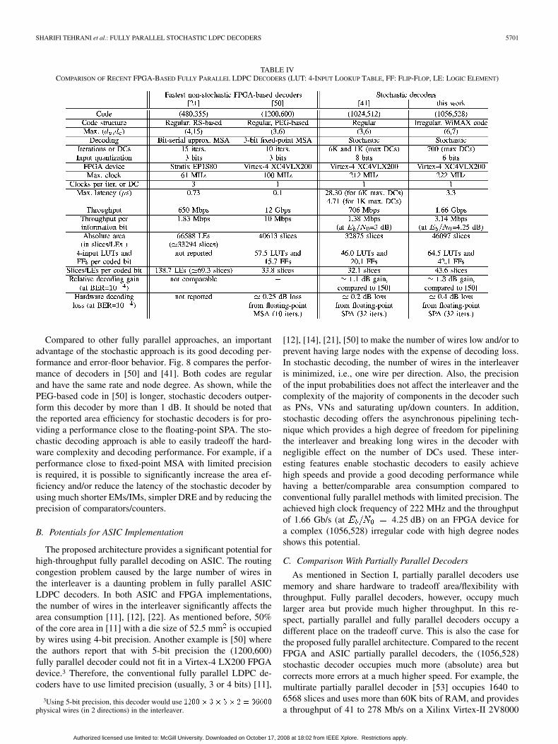
Table IV compares different aspects of the most recentFPGA-based fully parallel LDPC decoders. To our knowl-edge, the decoders in [50] and [21] are the fastest and thesecond fastest (nonstochastic) FPGA-based fully parallelLDPC decoders, respectively. The decoder in [50] decodesa (1200,600) regular code which is constructed based on theProgressive-Edge-Growth (PEG) method. The throughput ofthe decoder is 12 Gb/s. This throughput was achieved by em-ploying 3-bit fixed-point MSA with ten iterations. The decoderin [21] decodes a (480,355) regular code with a throughput of650 Mb/s using bit-serial approximate MSA with 15 iterations.Also, the decoder in [41] is a (1024,512) stochastic decoderwith a throughput of 706 Mb/s at a BER of . Compared tothe regular code used in [41], the (1056,528) code in this paperhas a much more complex structure due to its irregularity andhigh degree nodes.
Table IV gives the throughput efficiency per information bitfor each decoder. As discussed in Section V-C, the throughput ofthe (1056,528) decoder varies at different SNRs. For example,the decoder provides a throughput of 694 Mb/s at a2.5 dB and at 4.25 dB
the throughput is about 1.66 Gb/s. This throughput is be-yond the requirements of most applications. Compared to [50]and [21], the stochastic decoder has a higher latency. This la-tency is however within an acceptable range for many appli-cations. Usually, a latency limit of about 6 s is assumed forchannel decoders in applications such as WiMAX. In addition,as mentioned before, for applications with more strict latency re-quirements, it is possible to tradeoff the decoding performanceand the latency (see Fig. 12).
Table IV also gives the absolute area as well as area efficiencybased on the number of four-input lookup tables and flip-flopsper coded bit and, slices per coded bit. Note that a Logic Elementin the Altera Stratix architecture has one four-input lookup tableand one flip-flop [51] which is half of the resources of a slice ina Xilinx Virtex-4 architecture [52]. Since the number of lookuptables and flip-flops were not reported in [21], the comparisonwith this decoder is based on the approximate slice per codedbit efficiency. The area efficiency of the stochastic decoder isbetter than the bit-serial decoder in [21]. Compared to [50], thestochastic decoder needs more lookup tables and flip-flops percoded bit (but offers about 1.3 dB decoding gain as shown inFig. 8). The majority of this difference is due to the higher de-gree of VNs. As shown, the stochastic decoder in [41], with thesame rate and node degrees as in [50], needs much less resourcesthan this work and offers a better slice per coded bit efficiencycompared to [50].
Authorized licensed use limited to: McGill University. Downloaded on October 17, 2008 at 18:02 from IEEE Xplore. Restrictions apply.
SHARIFI TEHRANI et al.: FULLY PARALLEL STOCHASTIC LDPC DECODERS 5701
Compared to other fully parallel approaches, an importantadvantage of the stochastic approach is its good decoding per-formance and error-floor behavior. Fig. 8 compares the perfor-mance of decoders in [50] and [41]. Both codes are regularand have the same rate and node degree. As shown, while thePEG-based code in [50] is longer, stochastic decoders outper-form this decoder by more than 1 dB. It should be noted thatthe reported area efficiency for stochastic decoders is for pro-viding a performance close to the floating-point SPA. The sto-chastic decoding approach is able to easily tradeoff the hard-ware complexity and decoding performance. For example, if aperformance close to fixed-point MSA with limited precisionis required, it is possible to significantly increase the area ef-ficiency and/or reduce the latency of the stochastic decoder byusing much shorter EMs/IMs, simpler DRE and by reducing theprecision of comparators/counters.
B. Potentials for ASIC Implementation
The proposed architecture provides a significant potential forhigh-throughput fully parallel decoding on ASIC. The routingcongestion problem caused by the large number of wires inthe interleaver is a daunting problem in fully parallel ASICLDPC decoders. In both ASIC and FPGA implementations,the number of wires in the interleaver significantly affects thearea consumption [11], [12], [22]. As mentioned before, 50%of the core area in [11] with a die size of 52.5 mm is occupiedby wires using 4-bit precision. Another example is [50] wherethe authors report that with 5-bit precision the (1200,600)fully parallel decoder could not fit in a Virtex-4 LX200 FPGAdevice.3 Therefore, the conventional fully parallel LDPC de-coders have to use limited precision (usually, 3 or 4 bits) [11],
3Using 5-bit precision, this decoder would use ����� �� �� � � �����
physical wires (in 2 directions) in the interleaver.
[12], [14], [21], [50] to make the number of wires low and/or toprevent having large nodes with the expense of decoding loss.In stochastic decoding, the number of wires in the interleaveris minimized, i.e., one wire per direction. Also, the precisionof the input probabilities does not affect the interleaver and thecomplexity of the majority of components in the decoder suchas PNs, VNs and saturating up/down counters. In addition,stochastic decoding offers the asynchronous pipelining tech-nique which provides a high degree of freedom for pipeliningthe interleaver and breaking long wires in the decoder withnegligible effect on the number of DCs used. These inter-esting features enable stochastic decoders to easily achievehigh speeds and provide a good decoding performance whilehaving a better/comparable area consumption compared toconventional fully parallel methods with limited precision. Theachieved high clock frequency of 222 MHz and the throughputof 1.66 Gb/s (at 4.25 dB) on an FPGA device fora complex (1056,528) irregular code with high degree nodesshows this potential.
C. Comparison With Partially Parallel Decoders
As mentioned in Section I, partially parallel decoders usememory and share hardware to tradeoff area/flexibility withthroughput. Fully parallel decoders, however, occupy muchlarger area but provide much higher throughput. In this re-spect, partially parallel and fully parallel decoders occupy adifferent place on the tradeoff curve. This is also the case forthe proposed fully parallel architecture. Compared to the recentFPGA and ASIC partially parallel decoders, the (1056,528)stochastic decoder occupies much more (absolute) area butcorrects more errors at a much higher speed. For example, themultirate partially parallel decoder in [53] occupies 1640 to6568 slices and uses more than 60K bits of RAM, and providesa throughput of 41 to 278 Mb/s on a Xilinx Virtex-II 2V8000
Authorized licensed use limited to: McGill University. Downloaded on October 17, 2008 at 18:02 from IEEE Xplore. Restrictions apply.
5702 IEEE TRANSACTIONS ON SIGNAL PROCESSING, VOL. 56, NO. 11, NOVEMBER 2008
device. Also, the partially parallel (8176,7154) decoder in [54]uses about 23 K to 27 K slices and 128 block RAMs of a XilinxVirtexII-6000 FPGA device and, provides a throughput of172 Mb/s with 15 decoding iterations. Another recent exampleis the ASIC implementation of a partially parallel (1024,506)decoder in [55] with a throughput of 31.2 Mb/s with eightdecoding iterations.
VII. CONCLUSION
We proposed an architecture for fully parallel stochasticLDPC decoders. Using this architecture, we demonstratedthe performance of a fully parallel stochastic LDPC decoderthat decodes a state-of-the-art irregular (1056,528) code on aXilinx Virtex-4 LX200 FPGA device. This decoder exploitsseveral novel architectural techniques, provides a throughputof 1.66 Gb/s at 4.25 dB (BER of ) and,achieves decoding performance within 0.5 and 0.25 dB loss offloating-point SPA with 32 and 16 iterations, respectively. Thedecoder also shows similar error-floor behavior as floating-pointSPA with 32 iterations. To our knowledge, this decoder is thefirst stochastic LDPC decoder which decodes a state-of-the-artcode and it is the first irregular and one of the fastest and mostarea-efficient fully parallel LDPC decoders implemented onFPGA.
APPENDIX
PROOF OF STOCHASTIC VN AND PN OPERATIONS
Consider the XOR gate in Fig. 3(b) and its input stochasticstreams with and . Theoutput bit is 1 when and , or when and
. Therefore, .The output of other boolean operations is calculated similarly.
Now consider the VN structure in Fig. 3(a). This structure canbe represented as a Markov chain with two states (0 state and 1state). The probability (transition) matrix of this chain is
where in is the probability of transition from state to. The probability of having 1 in the steady state
of the chain (i.e., ) is calculated by computingthe eigenvector of with respect to an eigenvalue of 1, whichis equal to .
ACKNOWLEDGMENT
The authors would like to thank the reviewers and the asso-ciate editor for providing helpful comments.
REFERENCES
[1] R. G. Gallager, “Low density parity check codes,” IRE Trans. Inf.Theory, vol. 8, no. , pp. 21–28, Jan. 1962.
[2] D. J. C. MacKay and R. M. Neal, “Near Shannon limit performanceof low density parity check codes,” Electron. Lett., vol. 32, no. 18, pp.1645–1646, 1996.
[3] The Digital Video Broadcasting Standard [Online]. Available: www.dvb.org
[4] The IEEE P802.3an 10GBASE-T Task Force [Online]. Available:www.ieee802.org/3/an
[5] The IEEE 802.16 Working Group [Online]. Available: http://www.ieee802.org/16/
[6] The IEEE 802.11n Working Group [Online]. Available: http://www.ieee802.org/11/
[7] J. Pearl, Probabilistic Reasoning in Intelligent Systems: Networks ofPlausible Inference. San Mateo, CA: Morgan Kaufmann, 1988.
[8] N. Wiberg, “Codes and Decoding on General Graphs,” Ph.D. dis-sertation, Electrical Engineering Dept., Linkoping Univ,, Linkoping,Sweden, 1996.
[9] F. Kschischang, B. Frey, and H. Loeliger, “Factor graphs and the sum-product algorithm,” IEEE Trans. Inf. Theory, vol. 47, pp. 498–519, Feb.2001.
[10] P. Urard et al., “A 135 Mb/s DVB-S2 compliant codec based on64,800b LDPC and BCH codes,” in IEEE ISSCC Dig. Tech. Papers,Feb. 2005.
[11] A. Blanksby and C. Howland, “A 690-mw 1-Gb/s 1024-b rate-1/2 low-density parity-check code decoder,” IEEE J. Solid-State Circuits, vol.37, no. 3, pp. 404–412, Mar. 2002.
[12] A. Darabiha, A. C. Carusone, and F. R. Kschischang, “A 3.3-Gbps bit-serial block-interlaced min-sum LDPC decoder in 0.13-�m CMOS,”in Proc. Custom Integrated Circuits Conf., Sep. 2007, pp. 459–462.
[13] A. Darabiha, A. C. Carusone, and F. R. Kschischang, “Block-interlacedLDPC decoders with reduced interconnect complexity,” IEEE Trans.Circuits Syst. II, Exp. Briefs, vol. 55, no. 1, pp. 74–78, Jan. 2008.
[14] A. Darabiha, A. C. Carusone, and F. R. Kschischang, “Multi-Gbit/Seclow density parity check decoders with reduced interconnect com-plexity,” in IEEE Int. Symp. Circuits Syst., San Jose, CA, May 2005,pp. 5194–5197.
[15] E. Boutillon, J. Castura, and F. Kschischang, “Decoder-first codedesign,” in Proc. 2nd Int. Symp. Turbo Codes Related Topics, Brest,France, Sep. 2002, pp. 459–462.
[16] E. Yeo, B. Nikolic, and V. Anantharam, “Iterative decoder architec-tures,” IEEE Commun. Mag., vol. 41, no. 8, pp. 132–140, Aug. 2003.
[17] M. Mansour and N. Shanbhag, “High-throughput LDPC decoders,”IEEE Commun. Mag., vol. 11, no. 6, pp. 976–996, Dec. 2003.
[18] M. Mansour and N. Shanbhag, “A 640-Mb/s 2048-bit programmableLDPC decoder chip,” IEEE J. Solid-State Circuits, vol. 41, pp.684–698, Mar. 2006.
[19] J. Chen et al., “Reduced-complexity decoding of LDPC codes,” IEEETrans. Commun., vol. 53, no. 8, pp. 1288–1299, Aug. 2005.
[20] T. Zhang and K. Parhi, “Joint (3,k)-regular LDPC code and de-coder/encoder design,” IEEE Trans. Signal Process., vol. 52, no. 4,pp. 1065–1079, Apr. 2004.
[21] A. Darabiha, A. C. Carusone, and F. R. Kschischang, “A bit-serialapproximate min-sum LDPC decoder and FPGA implementation,” inProc. IEEE Int. Symp. Circuits Syst. (ISCAS), Greece, May 2006, pp.149–152.
[22] T. L. Brandon et al., “A scalable LDPC decoder ASIC architecture withbit-serial message exchange,” Integration, The VLSI J., vol. 41, no. 3,pp. 385–398, May 2008.
[23] J. Zhang and M. P. C. Fossorier, “A modified weighted bit-flipping de-coding of low-density parity-check codes,” IEEE Commun. Lett., vol.8, pp. 165–167, Mar. 2004.
[24] M. Jiang, C. Zhao, Z. Shi, and Y. Chen, “An improvement on the mod-ified weighted bit flipping decoding algorithm for LDPC codes,” IEEECommun. Lett., vol. 9, pp. 814–816, Sep. 2005.
[25] N. Mobini, A. H. Banihashemi, and S. Hemati, “A differentialbinary message-passing LDPC decoder,” in Proc. IEEE GlobalTelecomm. Conf. (IEEE GLOBECOM), Washington, DC, Nov. 2007,pp. 1561–1565.
[26] S. Seo, T. Mudge, Y. Zhu, and C. Chakrabarti, “Design and analysis ofLDPC decoders for software defined radio,” in Proc. IEEE Workshopon Signal Processing Systems (SiPS), Shanghai, China, Oct. 2007, pp.210–215.
[27] S. Hemati, A. Banihashemi, and C. Plett, “A 0.18 �m analog min-sumiterative decoder for a (32,8) low-density parity-check (LDPC) code,”IEEE J. Solid-State Circuits, vol. 41, pp. 2531–2540, Nov. 2006.
[28] F. Lustenberger et al., “All-analog decoder for a binary (18,9,5) tail-biting trellis code,” in Proc. Eur. Solid-State Circuits Conf., 1999, pp.362–365.
[29] M. Moerz, T. Gabara, R. Yan, and J. Hagenauer, “An analog 0.25 �mbiCMOS tailbiting map decoder,” in Proc. IEEE Custom IntegratedCircuits Conf., Feb. 2000, pp. 356–357.
[30] V. Gaudet and G. Gulak, “A 13.3-Mb/s 0.35 �m CMOS analog turbodecoder IC with a configurable interleaver,” IEEE J. Solid-State Cir-cuits, vol. 38, pp. 2010–2015, Nov. 2003.
Authorized licensed use limited to: McGill University. Downloaded on October 17, 2008 at 18:02 from IEEE Xplore. Restrictions apply.
SHARIFI TEHRANI et al.: FULLY PARALLEL STOCHASTIC LDPC DECODERS 5703
[31] C. Winstead, J. Dai, S. Yu, C. Myers, R. Harrison, and C. Schlegel,“CMOS analog map decoder for (8,4) Hamming code,” IEEE J. Solid-State Circuits, vol. 39, pp. 122–131, Jan. 2004.
[32] D. Vogrig, A. Gerosa, A. Neviani, A. G. I. Amat, G. Montorsi, and S.Benedetto, “A 0.35 �m CMOS analog turbo decoder for the 40-bit rate1/3 UMTS channel code,” IEEE J. Solid-State Circuits, vol. 40, pp.753–762, Mar. 2005.
[33] M. Arzel et al., “Analog slice turbo decoding,” in Proc. IEEE Int. Symp.Circuits Syst., May 2005, pp. 332–335.
[34] B. Gaines, Advances in Information Systems Science. New York:Plenum, 1969, ch. 2, pp. 37–172.
[35] V. Gaudet and A. Rapley, “Iterative decoding using stochastic compu-tation,” Electron. Lett, vol. 39, no. 3, pp. 299–301, Feb. 2003.
[36] A. Rapley, C. Winstead, V. Gaudet, and C. Schlegel, “Stochastic iter-ative decoding on factor graphs,” in Proc. 3rd Int. Symp. Turbo CodesRelated Topics, Brest, France, Sep. 2003, pp. 507–510.
[37] W. J. Gross, V. Gaudet, and A. Milner, “Stochastic implementationof LDPC decoders,” in Proc. 39th Asilomar Conf. Signals, Systems,Computers, Pacific Grove, CA, Nov. 2005, pp. 713–717.
[38] C. Winstead, V. Gaudet, A. Rapley, and C. Schlegel, “Stochastic iter-ative decoders,” in Proc. IEEE Int. Symp. Information Theory (ISIT),Sep. 2005, pp. 1116–1120.
[39] C. Winstead, “Error-control decoders and probabilistic computation,”in Proc. Tohoku Univ. 3rd Student-Organizing Int. Mini-Conf. Infor-mation Electronics System (SOIM-COE), Sendai, Japan, Oct. 2005, pp.349–352.
[40] S. Sharifi Tehrani, W. J. Gross, and S. Mannor, “Stochastic decodingof LDPC codes,” IEEE Commun. Lett., vol. 10, no. 10, pp. 716–718,Oct. 2006.
[41] S. Sharifi Tehrani, S. Mannor, and W. J. Gross, “An area-efficientFPGA-based architecture for fully-parallel stochastic LDPC de-coding,” in Proc. IEEE Workshop on Signal Processing Systems(SiPS), Shanghai, China, Oct. 2007, pp. 255–260.
[42] C. B. Schlegel and L. C. Perez, Trellis and Turbo Coding. Piscataway,NJ: IEEE Press, 2004.
[43] A. Anastasopoulos, “A comparison between the sum-product and themin-sum iterative detection algorithms based on density evolution,” inProc. IEEE Global Telecomm. Conf. (IEEE GLOBECOM), Nov. 2001,vol. 2, pp. 1021–1025.
[44] F. Guilloud, E. Boutillon, and J.-L. Danger, “�-min decoding algorithmof regular and irregular LDPC codes,” in Proc. 3rd Int. Symp. TurboCodes (ISTC), Brest, France, Sep. 1–5, 2003, pp. 451–454.
[45] S. Howard, C. Schlegel, and V. Gaudet, “A degree-matched check nodeapproximation for LDPC decoding,” in Proc. IEEE Int. Symp. Informa-tion Theory, Adelaide, Australia, Sep. 4–9, 2005, pp. 1131–1135.
[46] S. Sharifi Tehrani, S. Mannor, and W. J. Gross, “Survey of stochasticcomputation on factor graphs,” in Proc. 37th IEEE Int. Symp. Multiple-Valued Logic, Oslo, Norway, May 2007, pp. 54–59.
[47] M. R. Yazdani, S. Hemati, and A. Banihashemi, “Improving beliefpropagation on graphs with cycles,” IEEE Commun. Lett., vol. 8, no. 1,pp. 57–59, Jan. 2004.
[48] T. J. Richardson and R. Urbanke, “The capacity of low-densityparity-check codes under message-passing decoding,” IEEE Trans.Inf. Theory, vol. 47, pp. 599–618, Feb. 2001.
[49] N. Onizawa, T. Ikeda, T. Hanyu, and V. Gaudet, “3.2-Gb/s 1024-brate-1/2 LDPC decoder chip using a flooding-type update-schedule al-gorithm,” in Proc. 50th IEEE Midwest Symp. Circuits Systems, Brest,France, Aug. 2007, pp. 217–220.
[50] R. Zarubica, S. G. Wilson, and E. Hall, “Multi-Gbps FPGA-based lowdensity parity check (LDPC) decoder design,” presented at the IEEEGlobal Telecomm. Conf. (IEEE GLOBECOM), Washington DC, Nov.2007.
[51] Stratix Device Handbook, Altera Corporation, San Jose, CA [Online].Available: www.altera.com
[52] Virtex-4 User Guide, Xilinx Corp., San Jose, CA [Online]. Available:www.xilinx.com
[53] K. K. Gunnam, G. S. Choi, M. B. Yeary, and M. Atiquzzaman,“VLSI architectures for layered decoding for irregular LDPC codesof WiMax,” in Proc. IEEE Int. Conf. Communications, Jun. 2007, pp.4542–4547.
[54] Z. Wang and Z. Cui, “Low-complexity high-speed decoder design forquasi-cyclic LDPC codes,” IEEE Trans. VLSI Systems, vol. 15, no. 1,pp. 104–114, Jan. 2007.
[55] G. Masera, F. Quaglio, and F. Vacca, “Implementation of a flexibleLDPC decoder,” IEEE Trans. VLSI Syst., vol. 54, no. 6, pp. 542–546,Jun. 2007.
Saeed Sharifi Tehrani (S’05) received the B.Sc. de-gree in computer engineering from Sharif Universityof Technology, Tehran, Iran, in 2002 and the M.Sc.degree in electrical and computer engineering fromthe University of Alberta, Edmonton, AB, Canada,in 2005. He is currently working towards the Ph.D.degree at the Department of Electrical and ComputerEngineering, McGill University, Montreal, QC,Canada.
His research interests include digital signalprocessing systems, low-complexity error-control-
coding techniques, and design and hardware implementation of iterativedecoders.
Mr. Sharifi Tehrani received the Post Graduate Scholarship Award from theAlberta Informatics Circle of Research Excellence (iCORE) during his M.Sc.study at the University of Alberta. He is also an awardee of the doctoral researchscholarship from the Fonds Québécois de la Recherche sur la Nature et les Tech-nologies (FQRNT) as well as a recipient of the Alexander Graham Bell CanadaGraduate Scholarship Doctoral Award (CGS D) from the Natural Science andEngineering Council of Canada (NSERC).
Shie Mannor (S’00–M’03) received the B.Sc. degreein electrical engineering, the B.A. degree in mathe-matics (both summa cum laude), and the Ph.D. degreein electrical engineering from the Technion—IsraelInstitute of Technology, Haifa, Israel, in 1996, 1996,and 2002, respectively.
During spring semester 2002, he was a Lecturer atthe Electrical Engineering Department of the Tech-nion. From 2002 to 2004, he was a Postdoctoral Asso-ciate with the Massachusetts Institute of Technology(MIT), Cambridge. He is currently an Assistant Pro-
fessor of Electrical and Computer Engineering at McGill University, Montreal,QC, Canada. His research interests include machine learning and pattern recog-nition, planning and control, multiagent systems, and communications.
Dr. Mannor was a Fulbright scholar in 2002, and he is currently a CanadaResearch Chair in Machine Learning.
Warren J. Gross (S’92–M’04) received the B.A.Sc.degree in electrical engineering from the Universityof Waterloo, Waterloo, ON, Canada, in 1996, and theM.A.Sc. and Ph.D. degrees from the University ofToronto, Toronto, ON, Canada, in 1999 and 2003,respectively.
Currently, he is an Assistant Professor with theDepartment of Electrical and Computer Engineering,McGill University, Montreal, QC, Canada. His re-search interests are in the design and applicationof signal processing microsystems and custom
computer architectures. In summers 2004 and 2005, he was a Visiting Professorat the Université de Bretagne-Sud, Lorient, France.
Dr. Gross is a member of the Design and Implementation of Signal ProcessingSystems Technical Committee of the IEEE Signal Processing Society. He servedas the General Chair of the Sixth Analog Decoding Workshop. He has served onthe Program Committees for the IEEE Workshop on Signal Processing Systems,the IEEE Symposium on Field-Programmable Custom Computing Machines,and the International Conference on Field-Programmable Logic and Applica-tions. He is a Member of the IEEE and a licensed Professional Engineer in theProvince of Ontario.
Authorized licensed use limited to: McGill University. Downloaded on October 17, 2008 at 18:02 from IEEE Xplore. Restrictions apply.


![5692 IEEE TRANSACTIONS ON WIRELESS …ddfe.curtin.edu.au/yurong/MultiwayRelay.pdf[2], the full-duplex multi-group multi-way relay channel has been investigated and time division multiple](https://static.documents.pub/doc/80x56/6066649b6671e708cb46000a/5692-ieee-transactions-on-wireless-ddfe-2-the-full-duplex-multi-group-multi-way.jpg)


