12
56g pam4 ibis ami modeling MIG SIPI Intel Corporation Jonggab Kil
56g pam4 ibis amimodeling
MIG SIPI Intel CorporationJonggab Kil
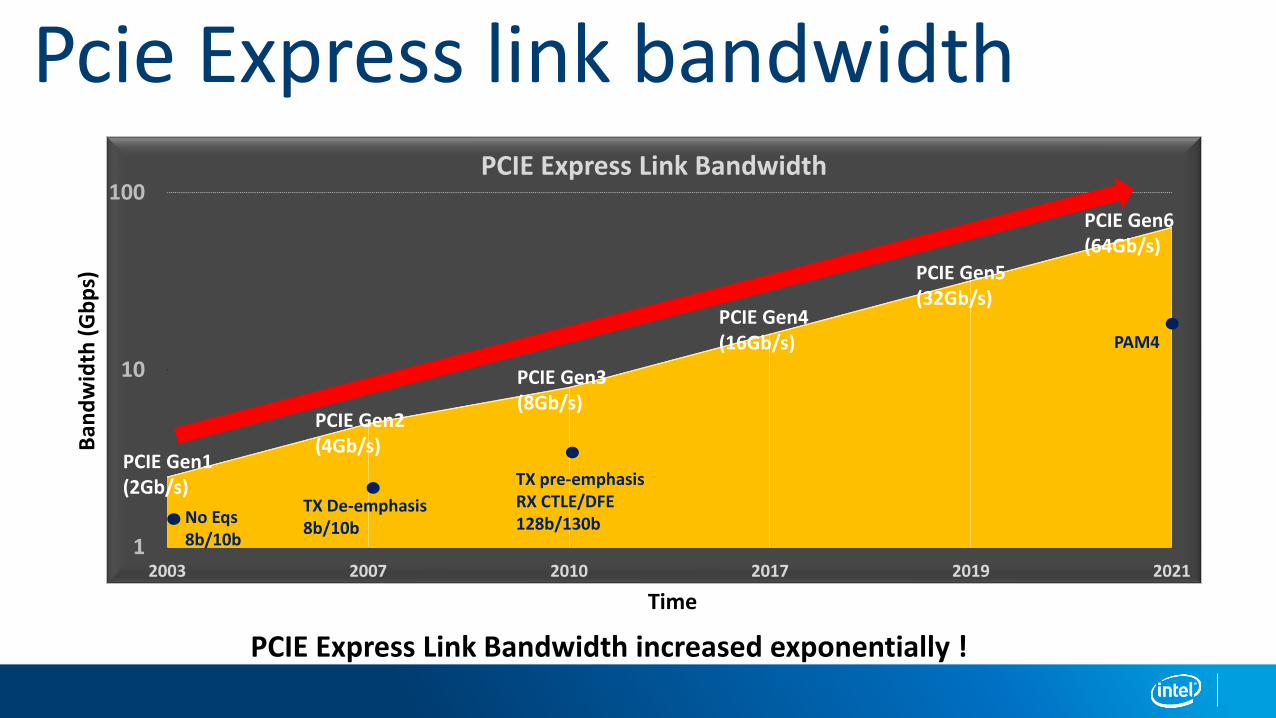
Pcie Express link bandwidth
1
10
100
2003 2007 2010 2017 2019 2021
PCIE Express Link Bandwidth
PCIE Express Link Bandwidth increased exponentially !
PCIE Gen6(64Gb/s)
PCIE Gen5(32Gb/s)
PCIE Gen4(16Gb/s)
PCIE Gen3(8Gb/s)
PCIE Gen2(4Gb/s)
PCIE Gen1(2Gb/s)
Ban
dw
idth
(G
bp
s)
Time
TX De-emphasis8b/10b
TX pre-emphasisRX CTLE/DFE128b/130b No Eqs
8b/10b
PAM4
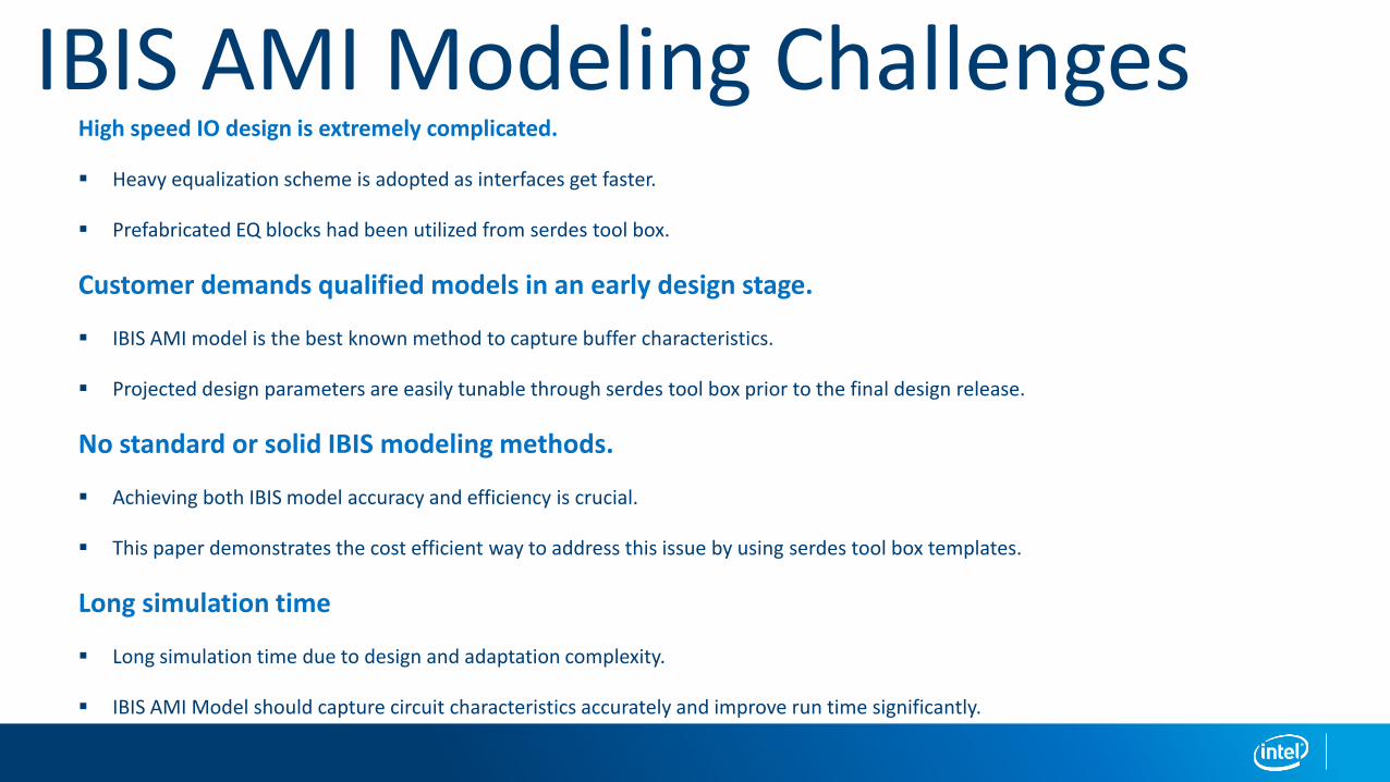
IBIS AMI Modeling ChallengesHigh speed IO design is extremely complicated.
▪ Heavy equalization scheme is adopted as interfaces get faster.
▪ Prefabricated EQ blocks had been utilized from serdes tool box.
Customer demands qualified models in an early design stage.
▪ IBIS AMI model is the best known method to capture buffer characteristics.
▪ Projected design parameters are easily tunable through serdes tool box prior to the final design release.
No standard or solid IBIS modeling methods.
▪ Achieving both IBIS model accuracy and efficiency is crucial.
▪ This paper demonstrates the cost efficient way to address this issue by using serdes tool box templates.
Long simulation time
▪ Long simulation time due to design and adaptation complexity.
▪ IBIS AMI Model should capture circuit characteristics accurately and improve run time significantly.
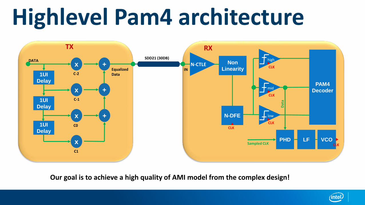
midPAM4
Decoder
high
low
PHD VCOLF
CLK
CLK
CLK
CLK
x
x
x
x
+
+
+
1UI
Delay
1UI
Delay
1UI
DelayC0
C1
C-1
C-2
DATA
Equalized Data
CLK
IN
Highlevel Pam4 architecture
SDD21 (30DB)
Our goal is to achieve a high quality of AMI model from the complex design!
N-CTLE Non
Linearity
N-DFE
TX RX
Sampled CLK
Dat
a
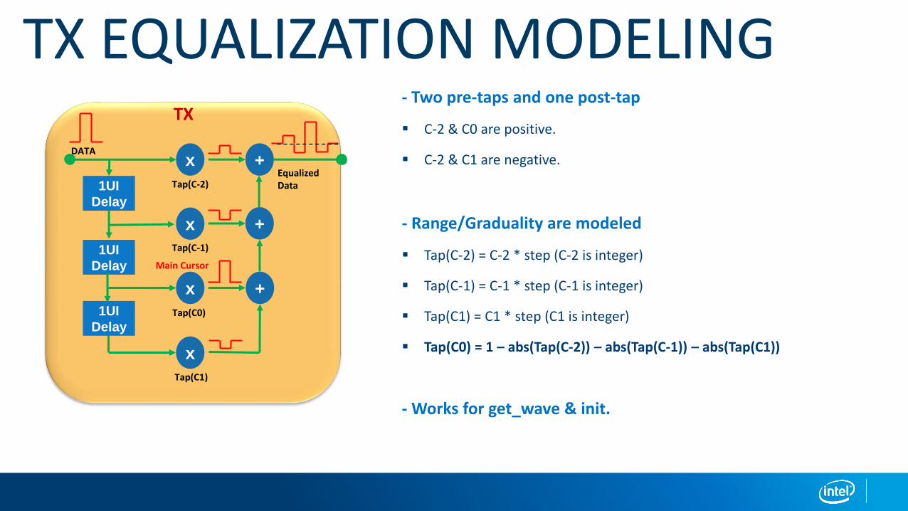
TX EQUALIZATION MODELING- Two pre-taps and one post-tap
▪ C-2 & C0 are positive.
▪ C-2 & C1 are negative.
- Range/Graduality are modeled
▪ Tap(C-2) = C-2 * step (C-2 is integer)
▪ Tap(C-1) = C-1 * step (C-1 is integer)
▪ Tap(C1) = C1 * step (C1 is integer)
▪ Tap(C0) = 1 – abs(Tap(C-2)) – abs(Tap(C-1)) – abs(Tap(C1))
- Works for get_wave & init.
x
x
x
x
+
+
+
1UI
Delay
1UI
Delay
1UI
DelayTap(C0)
Tap(C1)
Tap(C-1)
Tap(C-2)
DATA
Equalized Data
TX
Main Cursor
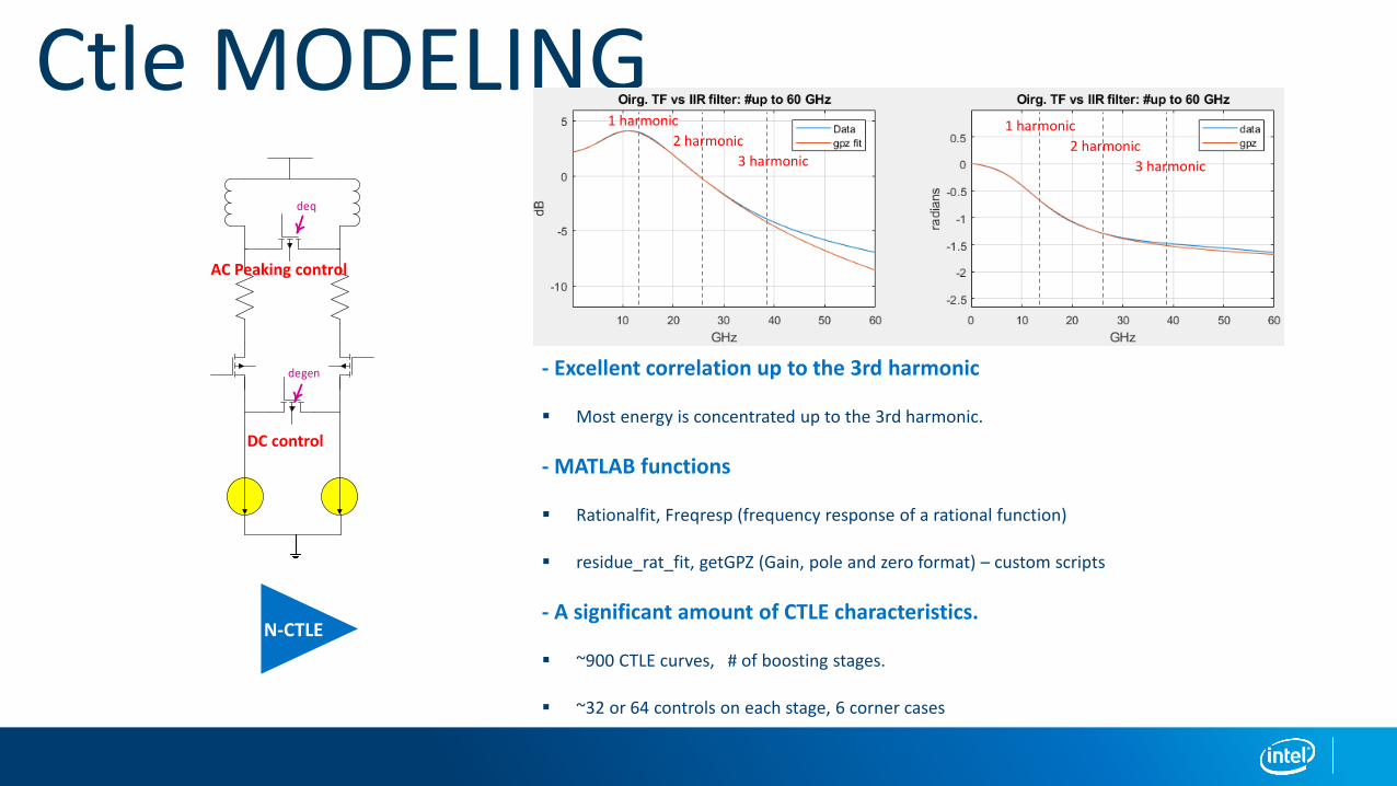
Ctle MODELING
- Excellent correlation up to the 3rd harmonic
▪ Most energy is concentrated up to the 3rd harmonic.
- MATLAB functions
▪ Rationalfit, Freqresp (frequency response of a rational function)
▪ residue_rat_fit, getGPZ (Gain, pole and zero format) – custom scripts
- A significant amount of CTLE characteristics.
▪ ~900 CTLE curves, # of boosting stages.
▪ ~32 or 64 controls on each stage, 6 corner cases
deq
degen
N-CTLE
1 harmonic
2 harmonic
3 harmonic
1 harmonic
2 harmonic
3 harmonic
AC Peaking control
DC control
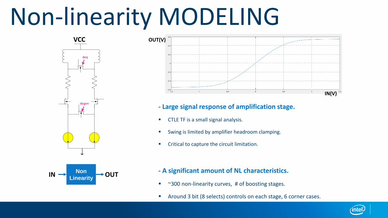
Non-linearity MODELING
- Large signal response of amplification stage.
▪ CTLE TF is a small signal analysis.
▪ Swing is limited by amplifier headroom clamping.
▪ Critical to capture the circuit limitation.
- A significant amount of NL characteristics.
▪ ~300 non-linearity curves, # of boosting stages.
▪ Around 3 bit (8 selects) controls on each stage, 6 corner cases.
deq
degen
Non
LinearityIN OUT
IN(V)
OUT(V)VCC

DFE/CDR MODELING
BangBang Clock Data Recovery
▪ Decision is made based on early or late clock to input data.
▪ BW = Data_rate * CDR_Step / Sample_rate
DFE NL behavior
▪ Slow loop response causes settling errors.
▪ Settling and offset errors are modeled in respect to each tap.
DFE step size/ range
▪ Each tap is modeled with a different step size and different tap weight range.CLK
N-DFE
mid
1UI
Delay
x
+
1UI
Delay
x
_
+
+
1UI
Delay
x+
C1
C2
C3
PHD VCOLFCLK
Sampled Signal edge
Data 1UI delay
1UI delay
1UI delay
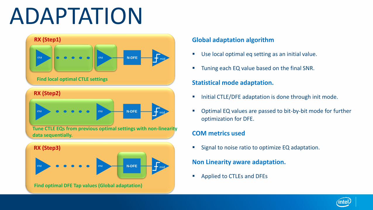
ADAPTATIONGlobal adaptation algorithm
▪ Use local optimal eq setting as an initial value.
▪ Tuning each EQ value based on the final SNR.
Statistical mode adaptation.
▪ Initial CTLE/DFE adaptation is done through init mode.
▪ Optimal EQ values are passed to bit-by-bit mode for further
optimization for DFE.
COM metrics used
▪ Signal to noise ratio to optimize EQ adaptation.
Non Linearity aware adaptation.
▪ Applied to CTLEs and DFEs
RX (Step1)
CTLE CTLE N-DFE mid
Find local optimal CTLE settings
RX (Step2)
CTLE CTLE N-DFE mid
Tune CTLE EQs from previous optimal settings with non-linearity data sequentially.
RX (Step3)
CTLE CTLE N-DFE mid
Find optimal DFE Tap values (Global adaptation)
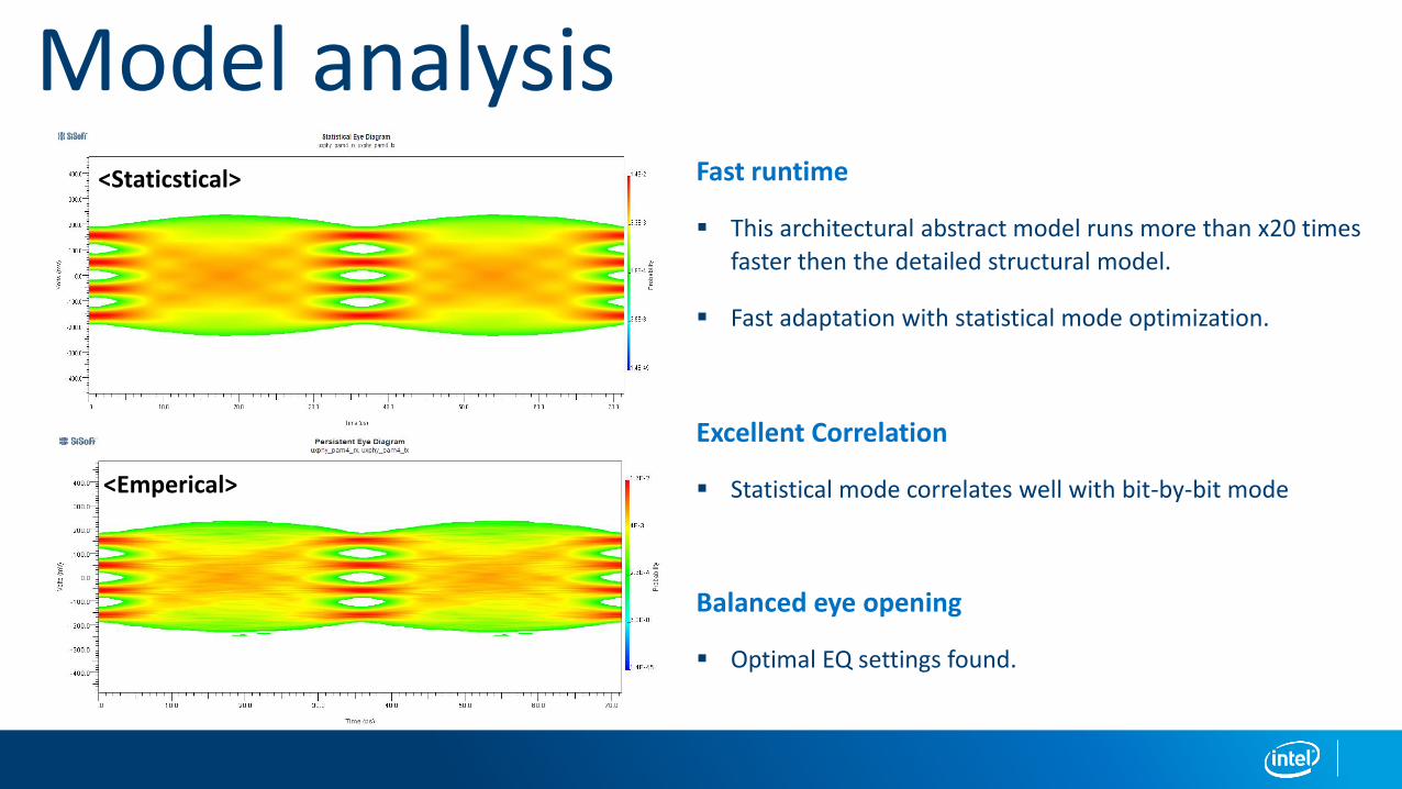
Model analysisFast runtime
▪ This architectural abstract model runs more than x20 times
faster then the detailed structural model.
▪ Fast adaptation with statistical mode optimization.
Excellent Correlation
▪ Statistical mode correlates well with bit-by-bit mode
Balanced eye opening
▪ Optimal EQ settings found.
<Staticstical>
<Emperical>
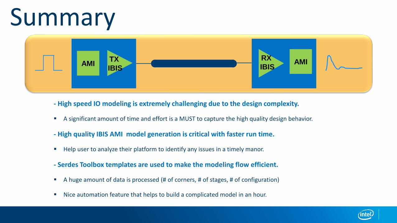
Summary
AMITX
IBISAMI
RX
IBIS
- High speed IO modeling is extremely challenging due to the design complexity.
▪ A significant amount of time and effort is a MUST to capture the high quality design behavior.
- High quality IBIS AMI model generation is critical with faster run time.
▪ Help user to analyze their platform to identify any issues in a timely manor.
- Serdes Toolbox templates are used to make the modeling flow efficient.
▪ A huge amount of data is processed (# of corners, # of stages, # of configuration)
▪ Nice automation feature that helps to build a complicated model in an hour.

Q&A


