Xerox Foreign Interface Guidelines SECTION 7 5750 5760 5765 5775 5790 5799 digital BookMark Digital Copier 212 (DC212) Digital Copier 214 (DC214) DocuColor 12 DocuColor 30 DocuColor 40 DocuColor 2045 DocuColor 2060 DocuColor Office 6 Document Centre 220 (DC220) Document Centre 230 (DC230) Document Centre 240 (DC240) Document Centre 255 (DC255) Document Centre 265 (DC265) Document Centre 332 (DC332) Document Centre 340 (DC340) Document Centre 420 (DC420) Document Centre 425 (DC425) Document Centre 432 (DC432) Document Centre 440 (DC440) Document Centre 460 (DC460) Document Centre 470 (DC470) Document Centre 480 (DC480) Document Centre 490 (DC490) Document Centre Color Series 50 (DCCS50) Document Centre System 35 (DCS35)
5750 5760 5765 5775 5790 5799 digital BookMark Digital Copier 212 (DC212) Digital Copier 214 (DC214) DocuColor 12 DocuColor 30 DocuColor 40 DocuColor 2045 DocuColor 2060 DocuColor Office 6 Document Centre 220 (DC220) Document Centre 230 (DC230) Document Centre 240 (DC240) Document Centre 255 (DC255) Document Centre 265 (DC265) Document Centre 332 (DC332) Document Centre 340 (DC340) Document Centre 420 (DC420) Document Centre 425 (DC425) Document Centre 432 (DC432) Document Centre 440 (DC440) Document Centre 460 (DC460) Document Centre 470 (DC470) Document Centre 480 (DC480) Document Centre 490 (DC490) Document Centre Color Series 50 (DCCS50) Document Centre System 35 (DCS35)
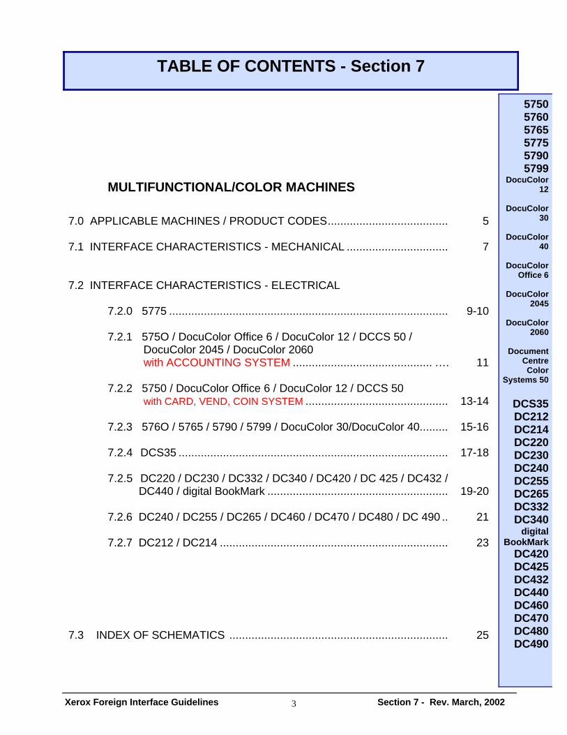
To provide the customer with information: 1.1 To access control of the machine 1.2 To obtain copy count information This document provides information regarding input and output requirements, applicable machine product codes, schematics and related materials. All correspondence regarding interface connections and machine operation must be made through the Xerox Field Service organization. Xerox Corporation requires that all accessories produced by outside vendors for attachment to Xerox products be approved by the applicable safety agency, eg. UL and CSA. Verification of this approval must be provided to Xerox prior to being entered on the Xerox list of approved suppliers. In instances where safety agency approval is not necessary or applicable, this requirement may be waived. Review approval, however, would have to be made by Xerox product safety and engineering. This review will require detailed information on the device, along with samples of the accessory for possible evaluation. Non-Xerox attachments to Xerox equipment must be made only through interface hardware provided and installed only by Xerox service personnel. The customer will be charged for hardware and installation at the prevailing rate. Non-Xerox accessory attachments installed to Xerox interface harness will be done by the customer or the non-Xerox accessory service personnel. Due to possible safety hazards and potential damage to the machine covers, under no circumstances are non-Xerox devices to be mounted directly to the Xerox machine. Remote mounting is left to the arrangements made between the customer and their supplier(s).
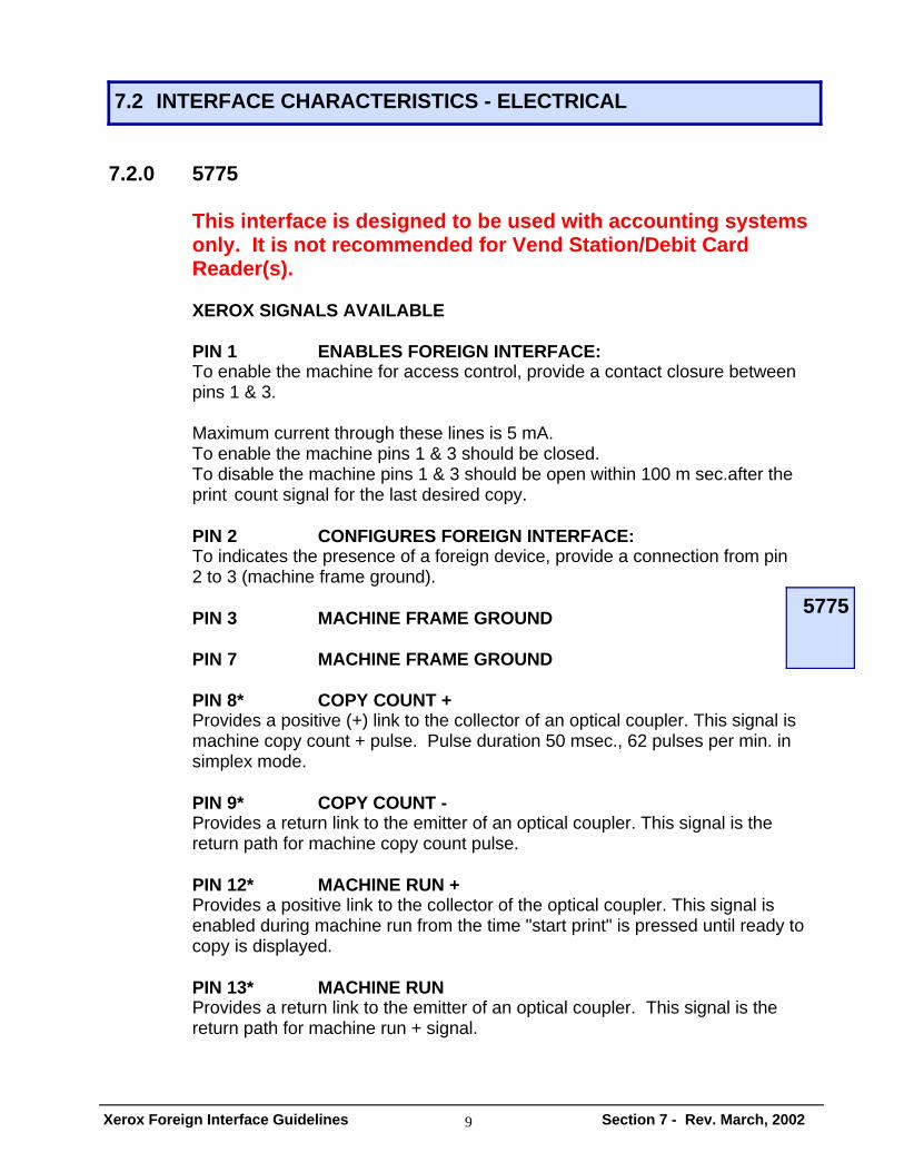
7.2.0 5775 This interface is designed to be used with accounting systems only. It is not recommended for Vend Station/Debit Card Reader(s). XEROX SIGNALS AVAILABLE PIN 1 ENABLES FOREIGN INTERFACE: To enable the machine for access control, provide a contact closure between pins 1 & 3. Maximum current through these lines is 5 mA. To enable the machine pins 1 & 3 should be closed. To disable the machine pins 1 & 3 should be open within 100 m sec.after the print count signal for the last desired copy. PIN 2 CONFIGURES FOREIGN INTERFACE: To indicates the presence of a foreign device, provide a connection from pin 2 to 3 (machine frame ground). PIN 3 MACHINE FRAME GROUND PIN 7 MACHINE FRAME GROUND PIN 8* COPY COUNT + Provides a positive (+) link to the collector of an optical coupler. This signal is machine copy count + pulse. Pulse duration 50 msec., 62 pulses per min. in simplex mode. PIN 9* COPY COUNT - Provides a return link to the emitter of an optical coupler. This signal is the return path for machine copy count pulse. PIN 12* MACHINE RUN + Provides a positive link to the collector of the optical coupler. This signal is enabled during machine run from the time "start print" is pressed until ready to copy is displayed. PIN 13* MACHINE RUN Provides a return link to the emitter of an optical coupler. This signal is the return path for machine run + signal.
(CONTINUED - 5775) PIN 14 MACHINE FRAME GROUND PIN 15 24 VOLTS FOR XEROX USE ONLY *ELECTRICAL REQUIREMENTS FOR OPTICAL COUPLER MAX COLLECTOR TO EMITTER VOLTAGE 20 VDC MAX COLLECTOR TO EMITTER CURRENT 148 MA MAX COLLECTOR TO EMITTER WATTAGE 148MW MESSAGE SET 'USE ACCESS DEVICE'
7.2.1 5750 / DocuColor 12 / Docucolor 2045 / Docucolor 2060 / Document Centre Color Series 50 / DocuColor Office 6 – FOREIGN INTERFACE FOR ACCOUNTING SYSTEMS
This is a special interface for a 5750 using Accounting devices rather than a Vend Station/ Debit Card Reader. Definition of the pins will vary for the two kits.
DocuColor 12 / Document Color Series 50 – NVM Selectable for this mode. XEROX SIGNAL DEFINITIONS
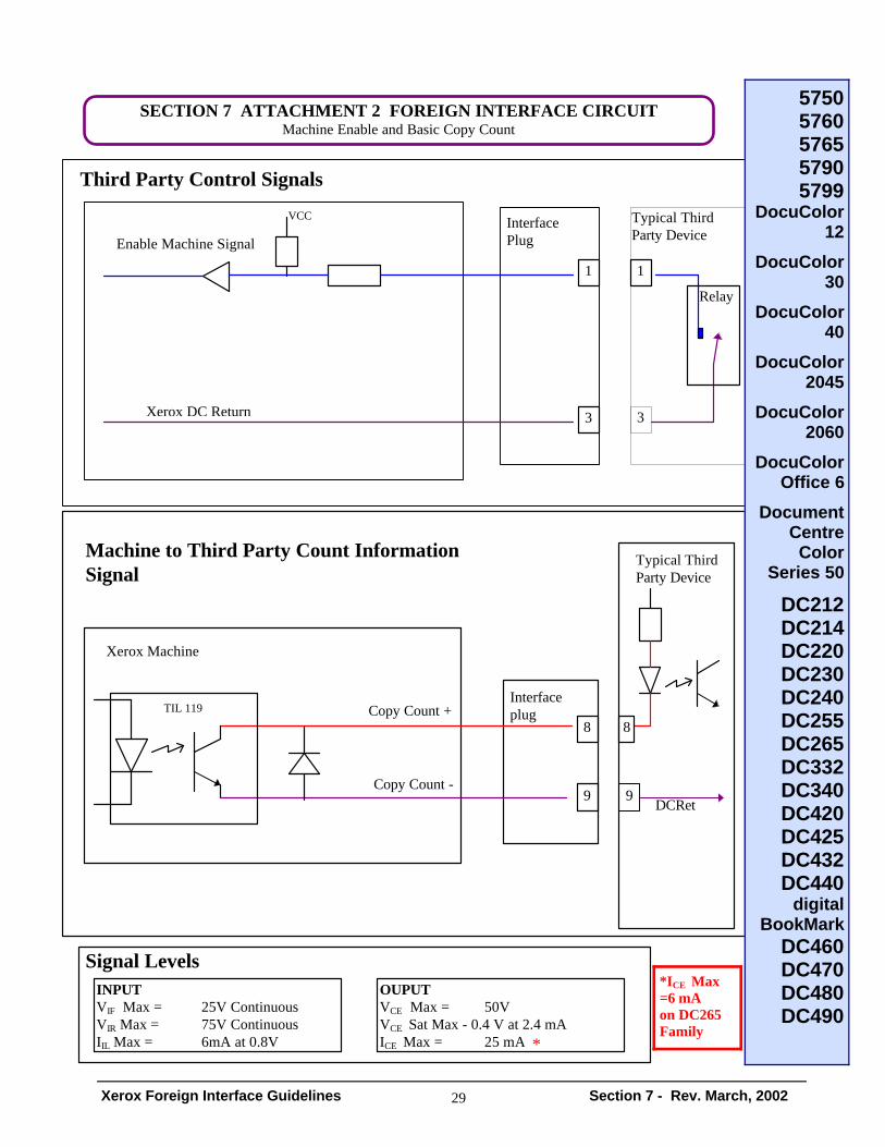
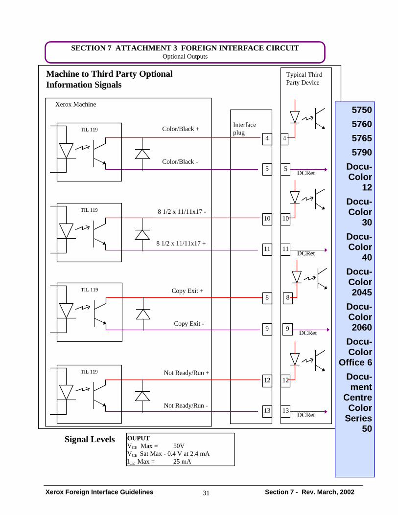
PIN 1 ENMACHFI A 'low' level signal (>0.8V) on this line enables the machine. Until enabled the machine keyboard will be inoperative with the user interface displaying the appropriate standby message. PIN 2 CONFIGFI Not Used - N/C PIN 3 MACHINE FRAME GROUND PINS 4&5 BLACK +/Color Black and White copy only - 200 ms pulse that occurs at the same time as COPYCNTFI. All paper sizes. This signal is generated by the machine when a black and white copy is being made. It can be used by the foreign device to count Black and White copies. PINS 8&9 COPYCNTFI +/- Copy count signal - 200 ms in duration. Copy is counted on the MajestiK copy output switch. This signal is generated by the machine when any copy is made. It can be used by the foreign device to count total copies. PINS 10&11 11X17"/8 1/2 x 11 +/- 11X17"/A3 copy count signal - 200 ms pulse that occurs at the same time as COPYCNTFI. Both COPYCNTFI+/- and 11X17"/ A3CNT +/ - active. Used in 3 pass color and full color only - not in B/W. This signal is generated by the machine when any copy is made. It can be used by foreign device to count 11X17"/A3 color copies. PINS 12&13 MACHRDY +/- Goes active when start print is activated and goes inactive when machine stops. This signal is generated by the machine to inform the foreign device that the machine is ready to make a copy.
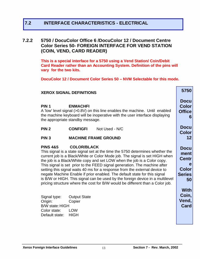
7.2.2 5750 / DocuColor Office 6 /DocuColor 12 / Document Centre Color Series 50- FOREIGN INTERFACE FOR VEND STATION (COIN, VEND, CARD READER) This is a special interface for a 5750 using a Vend Station/ Coin/Debit Card Reader rather than an Accounting System. Definition of the pins will vary for the two kits. DocuColor 12 / Document Color Series 50 – NVM Selectable for this mode. XEROX SIGNAL DEFINITIONS PIN 1 ENMACHFI A 'low' level signal (>0.8V) on this line enables the machine. Until enabled the machine keyboard will be inoperative with the user interface displaying the appropriate standby message. PIN 2 CONFIGFI Not Used - N/C PIN 3 MACHINE FRAME GROUND PINS 4&5 COLOR/BLACK This signal is a state signal set at the time the 5750 determines whether the current job is a Black/White or Color Mode job. The signal is set HIGH when the job is a Black/White copy and set LOW when the job is a Color copy. This signal is set prior to the FEED signal generation. The machine after setting this signal waits 40 ms for a response from the external device to negate Machine Enable if prior enabled. The default state for this signal is B/W or HIGH. This signal can be used by the foreign device in a multilevel pricing structure where the cost for B/W would be different than a Color job. Signal type: Output State Origin: Copier B/W state: HIGH Color state: LOW Default state: HIGH
(CONTINUED – 5750/DocuColor Office 6/DocuColor 12 with Vend/ Coin/Card Device) PINS 8&9 COPYCNTFI +/- This pulse is generated synchronously with the copier paper feed pulse from any tray including the bypass tray of the machine. This signal is asserted at the time of the paper feed of the machine from any tray. This FEED signal would be active low with a duration of 200ms. This signal can be used by the foreign device to collect the funds deposited. Signal type: Output PULSE Duration: 200 ms Origin: Copier Active state: LOW Inactive state: HIGH Default state: HIGH PINS 10&11 11X17"/8 1/2 x 11 +/- This signal is a state signal. When the paper size is 14.33" (B1 size) or less, the copier will assert this signal HIGH. When the paper size is larger than 14.33" (B1 size), the copier will assert this signal LOW. This signal will always be asserted LOW for any job from the bypass tray. This signal is set prior to the FEED signal generation. The machine after setting this signal waits 40 ms for a response from the external device to negate Machine Enable if prior enabled. The default state for this signal is HIGH. This signal is set at the same moment as BW / Color signal. This signal can be used by the foreign device in a multilevel pricing structure where the cost is greater for paper larger than 14.33". Signal type: Output State Origin: Copier Small size state: HIGH Large size state: LOW Default state: HIGH PINS 12&13 MACHRDY +/- Goes active when start print is activated and goes inactive when machine stops. This signal is generated by the machine to inform the foreign device that the machine is ready to make a copy.
7.2.3 5760 / 5765 / 5790 / 5799 / DocuColor 30 / DocuColor 40 This interface is designed to be used with accounting systems only. It is not recommended for Vend Station/Debit Card Reader(s).
XEROX SIGNAL DEFINITIONS PIN 1 ENMACHFI A 'low' level signal (>0.8V) on this line enables the machine. Until enabled the machine keyboard will be inoperative with the user interface displaying the appropriate standby message. PIN 2 CONFIGFI Not Used - N/C PIN 3 MACHINE FRAME GROUND PINS 4&5 BLACK +/- Black and White copy only - 200 ms pulse that occurs at the same time as COPYCNTFI. All paper sizes. This signal is generated by the machine when a black and white copy is being made. It can be used by the foreign device to count Black and White copies. PINS 8&9 COPYCNTFI +/- Copy count signal - 200 ms in duration. Copy is counted on the MajestiK copy output switch. This signal is generated by the machine when any copy is made. It can be used by the foreign device to count total copies. PINS 10&11 11X17"/A3CNT+/- 11X17"/A3 copy count signal - 200 ms in pulse that occurs at the same time as COPYCNTFI. Both COPYCNTFI+/- and 11X17"/ A3CNT +/ - active. Used in 3 pass color and full color only - not in B/W. This signal is generated by the machine when any copy is made. It can be used by foreign device to count 11X17"/A3 color copies. PINS 12&13 MACHRDY +/- Goes active when start print is activated and goes inactive when machine stops. This signal is generated by the machine to inform the foreign device that the machine is ready to make a copy.
7.2.4 DCS35 XEROX SIGNAL DEFINITIONS Pin 1 MACHINE ENABLE A 'low' level signal (>0.8V) on this line enables the machine. Until enabled the machine keyboard will be inoperative with the user interface displaying the appropriate standby message. Pin 2 EXTERNAL DEVICE ATTACHED A 'low` signal (>0.8V) on this line indicates to the copier control software than an accessory is connected to the foreign interface output. Pin 3 COMMON LOW INPUTS This line is the common return for the diodes of the input opto-isolators. The accessory should return each input used to this point. Pin 4 PREMIUM TRAY LARGE/SMALL + (NVM SWITCHABLE) A 'low' signal (<0.4V) is produced on this line to indicate that either a larger than A4/81/2X11 or a smaller than A4/81/2X11 paper tray is selected. The signal remains low until another tray is selected. Note: the copier can be set by a service engineer to switch this line low in either case or uniquely. Pin 5 PREMIUM TRAY LARGE/SMALL - This line is the return for the emitter of the input opto-isolators. Pin 6 PREMIUM REDUCE/ENLARGE + (NVM SWITCHABLE) A 'low' signal (<0.4V) is produced on this line to indicate that either a Reduc- tion / Enlargement ratio other than 100% has been selected. The signal re - mains low until the feature is deselected. Pin 7 PREMIUM REDUCE/ENLARGE + This line is the return for the emitter of the input opto-isolators.
(CONTINUED -DCS35) Pin 8 COPY COUNT A 'low' signal (<0.4V) is produced on this line each time a sheet of paper is fed. The signal remains low for 100-140ms and is synchronous with the paper feed signal. This signal is not generated if the paper feed is part of a job recovery. Pin 9 COPY COUNT - This line is the return for the emitter of the input opto-isolators. Pin 10 COPY EXIT A 'low` signal (<0.4V) is produced on this line each time a fused image is produced on a sheet of paper. The signal remains low for 100-140ms. This signal is not generated if the paper fed is part of a job recovery. PIN 11 COPY EXIT - Provides a return link to the emitter of an optical coupler. This signal is the return path for the COPY EXIT+ signal. PIN 12 NOT READY+ Provides a positive link to the collector of the optical coupler. To be turned ON at power on. To stay OFF during machine run state and Customer emulation mode in Diagnostics. PIN 13 NOT READY - Provides a return link to the emitter of an optical coupler. This signal is the return path for the NOT READY+ signal. PIN 14 MACHINE FRAME GROUND PIN 15 24 VOLTS (FOR XEROX USE ONLY) * Electrical Requirements for Optical Coupler Max Collector to Emitter Voltage 15 Vdc Max Collector to Emitter Current 8 mA Max Collector to Emitter Wattage 100 mW MESSAGE SET "Please insert Access Device"
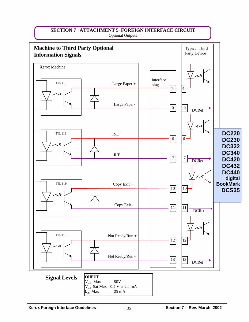
7.2.5 DC220 / DC230 / DC332 / DC340 / DC420 / DC425 / DC432 / DC440 / digital BookMark XEROX SIGNAL DEFINITIONS Pin 1 MACHINE ENABLE A 'low' level signal (>0.8V) on this line enables the machine. Until enabled the machine keyboard will be inoperative with the user interface displaying the appropriate standby message. Pin 3 COMMON LOW INPUTS This line is the common return for the diodes of the input opto-isolators. The accessory should return each input used to this point. Pin 4 PREMIUM TRAY LARGE/SMALL + (NVM SWITCHABLE) A 'low' signal (<0.4V) is produced on this line to indicate that either a larger than A4/81/2X11 or a smaller than A4/81/2X11 paper tray is selected. The signal remains low until another tray is selected. Note: the copier can be set by a service engineer to switch this line low in either case or uniquely. Pin 5 PREMIUM TRAY - This line is the return for the emitter of the input opto-isolators. Pin 6 PREMIUM REDUCE/ENLARGE + (NVM SWITCHABLE) A 'low' signal (<0.4V) is produced on this line to indicate that either a Reduction/Enlargement ratio other than 100% has been selected. The signal remains low until the feature is deselected. Pin 7 PREMIUM REDUCE/ENLARGE - This line is the return for the emitter of the input opto-isolators. Pin 8 COPY COUNT + A 'low' signal (<0.4V) is produced on this line each time a sheet of paper is fed. The signal remains low for 100-140ms and is synchronous with the paper feed signal. This signal is not generated if the paper feed is part of a job re- covery. Pin 9 COPY COUNT - This line is the return for the emitter of the input opto-isolators.
(CONTINUED - DC220/ DC230 / DC332 / DC340 /DC420 /DC425/ DC432 / DC440 / digital BookMark Pin 10 COPY EXIT + A 'low` signal (<0.4V) is produced on this line each time a fused image is produced on a sheet of paper. The signal remains low for 100-140ms. This signal is not generated if the paper fed is part of a job recovery. PIN 11 COPY EXIT - Provides a return link to the emitter of an optical coupler. This signal is the return path for the COPY EXIT+ signal. PIN 12 NOT READY+ Provides a positive link to the collector of the optical coupler. To be turned ON at power on. To stay OFF during machine run state and Customer emulation mode in Diagnostics. PIN 13 NOT READY - Provides a return link to the emitter of an optical coupler. This signal is the return path for the NOT READY+ signal. PIN 14 MACHINE FRAME GROUND MESSAGE SET "Please insert Access Device"
DC490** XEROX SIGNAL DEFINITIONS PIN 1 ENABLES FOREIGN INTERFACE To enable the machine provide contact closure (or zero ohms) between pins 1 and 3. PIN 2 FOREIGN INTERFACE PRESENT To indicate a device is present provide contact closure (or zero ohms) between pins 2 and 3. PIN 3 MACHINE FRAME GROUND PIN 8 COPYCOUNT + Copy count signal - 100 ms in duration. Provides a positive link to collector-side of opto-coupler. PIN 9 COPYCOUNT - Provides a return link to emitter-side of opto-coupler. Pin14 MACHINE GROUND PIN 15 5Vdc FOR XEROX SERVICE TECHNICIANS ONLY. THIRD PARTY VENDORS OR END-USER MUST NOT CONNECT TO THIS PIN AND SHOULD NOT USE THIS PIN AS A POWER SOURCE. * NOTE: INTERFACE CAN BE ENABLED BY CUSTOMER. THE PROCEDURE IS LOCATED ON PAGE 7-24 OF THE DOCUMENT CENTRE 240/255/265 REFERENCE GUIDE. **CUSTOMER WILL NEED THE FOREIGN INTERFACE BOARD—DC70FI(PRODUCT CODE) TO USE THIRD PARTY DEVICES.
7.2.1 DC212 / DC214 XEROX SIGNAL DEFINITIONS PIN 1 ENABLES FOREIGN INTERFACE: To enable the machine for access control, provide a contact closure between pins 1 & 3. Maximum current through these lines is 5 mA. To enable the machine pins 1 & 3 should be closed. To disable the machine pins 1 & 3 should be open within 100 m sec. after the print count signal for the last desired copy. PIN 3 MACHINE FRAME GROUND PIN 8* COPY COUNT + Provides a positive (+) link to the collector of an optical isolator. This signal is machine copy initiation count + pulse. The optical isolator conducts for a duration 100 msec., 135 pulses per min. in simplex mode or duplex mode. PIN 9* COPY COUNT - Provides a return link to the emitter of an optical isolator. This signal is the return path for machine copy initiation count pulse.
DC220 / DC230 / DC240 / DC255 /DC265 / DC332 / DC340 / DC420 / DC425 / DC432 / DC440 /digital BookMark DC460 / DC470 / DC480 /DC490 DocuColor 12 / DocuColor 30 / DocuColor40 / DocuColor 2045 / DocuColor 2060 / DocuColor Office 6 / Document Centre Color Series 50 SCHEMATICS for OPTIONAL OUTPUT SIGNALS ATTACHMENT 3 5750 / 5760 / 5765 / 5790 / 5799 / DocuColor 12 / DocuColor 30 / DocuColor40 / DocuColor 2045 / DocuColor 2060 / DocuColor Office 6 / Document Centre Color Series 50 ATTACHMENT 4 5775 ATTACHMENT 5 DC220 / DC230 / DC332 / DC340 / DC420 / DC432 / DC440 / digital BookMark / DCS35 NOTE: Since the equipment in this specification utilizes high speed integrated circuits in the control circuitry, attachment of unknown devices onto the control lines may cause abnormal machine operation due to the injection of voltage transients into the lines by static discharge or other causes. Precautions should be taken by the non-Xerox accessory manufacturers to prevent such voltage transients from being generated and introduced into the control lines.