Technical Data Manual 5773 596 - 03 06/2014 VITOCROSSAL 200 Gas-fired Condensing Boiler 1445 to 2245 MBH (423 to 658 kW) Please file in Service Binder Model Nos. and pricing : See Price List Vitocrossal 200 CM2 Series 400, 500, 620 and 620 TX High efficiency, gas-fired condensing boiler with pre-mix modulating cylinder burner for natural gas or liquid propane gas with Inox-Crossal heat exchanger made of high-grade SA 240-316 Ti stainless steel. For operation without low limit on boiler return water temperature. For closed loop hot water heating systems with maximum supply water temperatures of 210° F (99° C) for a maximum operating pressure of 75 psig. Heating input: 1445 to 2245 MBH (423 to 658 kW) Product may not be exactly as illustrated. H
Transcript
Technical Data Manual
5773 596 - 03 06/2014
VITOCROSSAL 200 Gas-fired Condensing Boiler1445 to 2245 MBH (423 to 658 kW)
Please file in Service Binder
Model Nos. and pricing : See Price List
Vitocrossal 200 CM2 Series 400, 500, 620 and 620 TX
High efficiency, gas-fired condensing boiler with pre-mix modulating cylinder burnerfor natural gas or liquid propane gas with Inox-Crossal heat exchanger made of high-grade SA 240-316 Ti stainless steel.For operation without low limit on boiler return watertemperature.For closed loop hot water heating systems with maximumsupply water temperatures of 210° F (99° C) for amaximum operating pressure of 75 psig.
Heating input: 1445 to 2245 MBH (423 to 658 kW)
Product may not be exactly as illustrated.
H
2
5773 5
96 -
03
Vitocrossal 200, CM2 400, 500, 620 and 620 TX Technical Data
Vitocrossal 200Product Information
Benefits at a glance: Inox-Crossal heat exchanger surface made of high-
grade SA 240-316 Ti stainless steel for high operational reliability and long service life. - Easy dispersal of condensate through vertical gas flues; therefore no concentration of condensate. - Increased self-cleaning effect through smooth stainless steel surfaces.
Highly efficient heat transfer and high condensation rate through - highly turbulent flow of flue gas through the heat exchanger. - boiler water and hot gases flowing in counter flow.
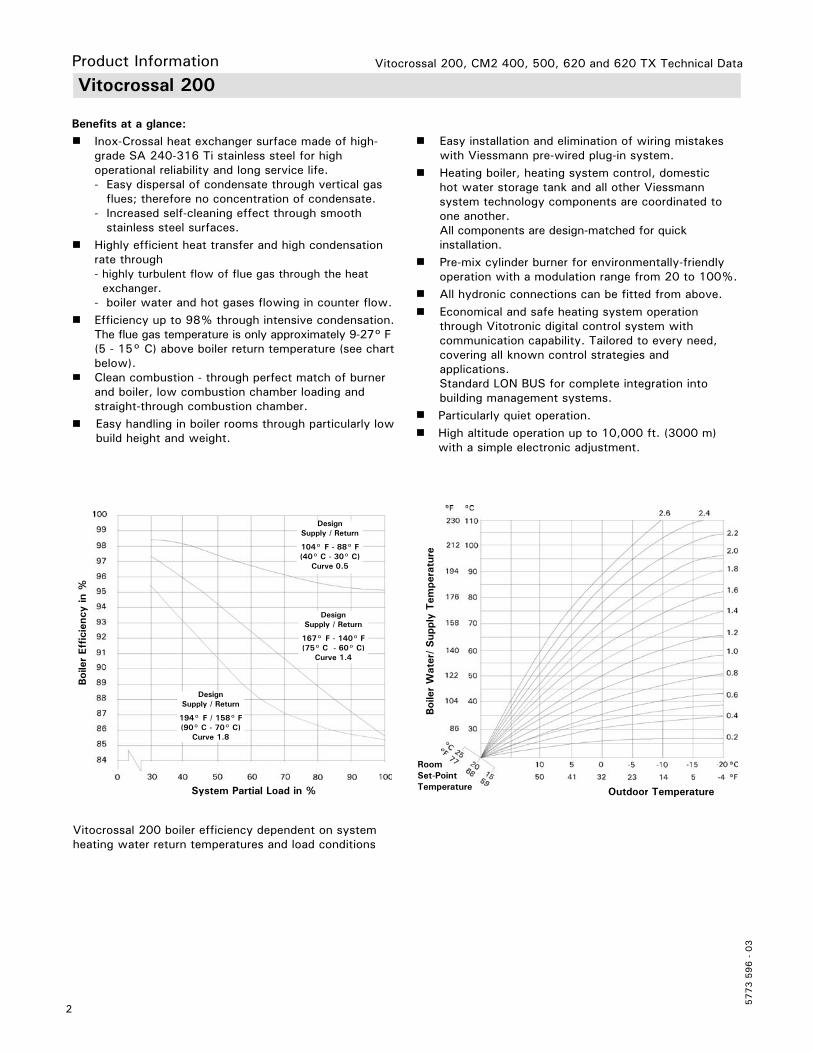
Efficiency up to 98% through intensive condensation. The flue gas temperature is only approximately 9-27° F (5 - 15° C) above boiler return temperature (see chart below).
Clean combustion - through perfect match of burner and boiler, low combustion chamber loading and straight-through combustion chamber.
Easy handling in boiler rooms through particularly low build height and weight.
Easy installation and elimination of wiring mistakes with Viessmann pre-wired plug-in system.
Heating boiler, heating system control, domestic hot water storage tank and all other Viessmann system technology components are coordinated to one another. All components are design-matched for quick installation.
Pre-mix cylinder burner for environmentally-friendly operation with a modulation range from 20 to 100%.
All hydronic connections can be fitted from above. Economical and safe heating system operation
through Vitotronic digital control system with communication capability. Tailored to every need, covering all known control strategies and applications. Standard LON BUS for complete integration into building management systems.
Particularly quiet operation. High altitude operation up to 10,000 ft. (3000 m)
with a simple electronic adjustment.
Vitocrossal 200 boiler efficiency dependent on system heating water return temperatures and load conditions
Boi
ler
Effici
ency
in %
System Partial Load in %
DesignSupply / Return
104° F - 88° F(40° C - 30° C)
Curve 0.5
DesignSupply / Return
167° F - 140° F(75° C - 60° C)
Curve 1.4
DesignSupply / Return
194° F / 158° F(90° C - 70° C)
Curve 1.8
Outdoor Temperature
Boi
ler
Wat
er/
Sup
ply
Tem
pera
ture
Room Set-Point Temperature
3
5773 5
96 -
03
Vitocrossal 200, CM2 400, 500, 620 and 620 TX Technical Data
Vitocrossal 200Product Information
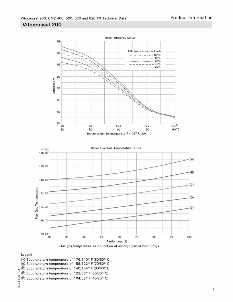
LegendA Supply/return temperature of 176/140° F (80/60° C)B Supply/return temperature of 158/122° F (70/50° C)C Supply/return temperature of 140/104° F (60/40° C)D Supply/return temperature of 122/86° F (50/30° C)E Supply/return temperature of 104/68° F (40/20° C)
Flue gas temperature as a function of average partial load firings.
4
5773 5
96 -
03
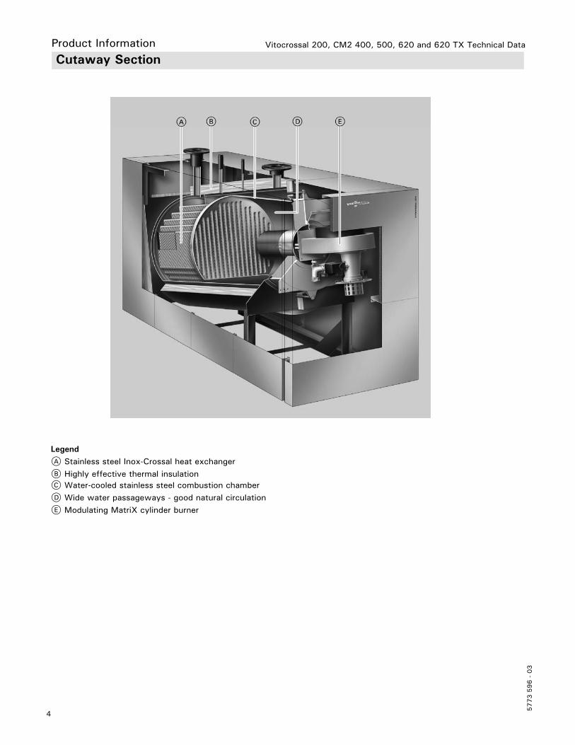
Vitocrossal 200, CM2 400, 500, 620 and 620 TX Technical DataProduct Information Cutaway Section
LegendA Stainless steel Inox-Crossal heat exchangerB Highly effective thermal insulationC Water-cooled stainless steel combustion chamberD Wide water passageways - good natural circulationE Modulating MatriX cylinder burner
5
5773 5
96 -
03
Vitocrossal 200, CM2 400, 500, 620 and 620 TX Technical Data
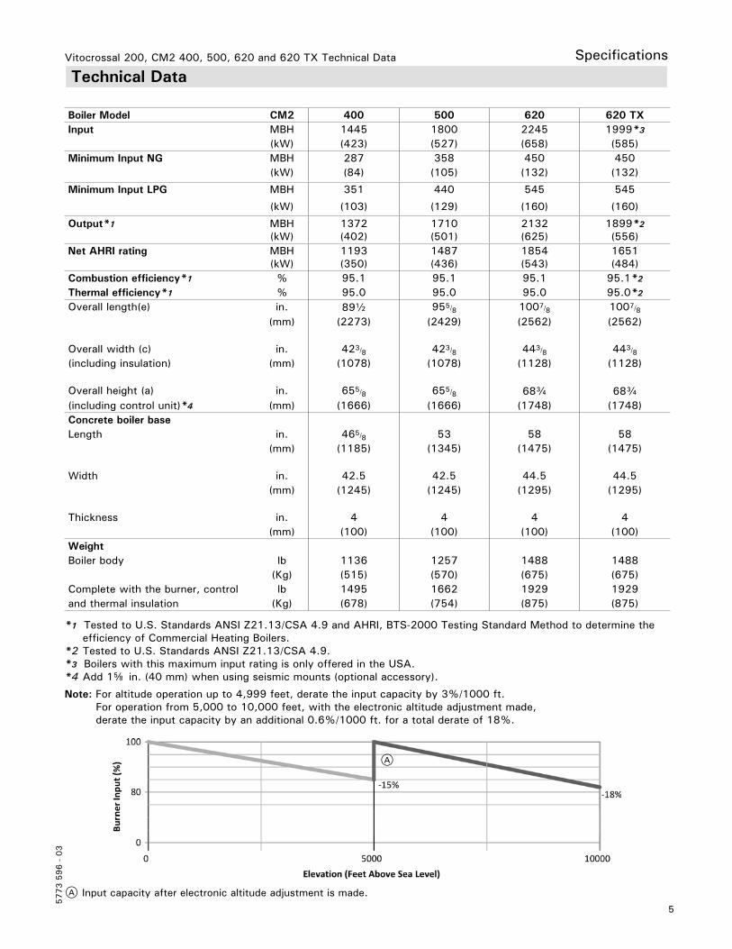
Overall height (a) in. 655/8 655/8 68c 68c(including control unit)*4 (mm) (1666) (1666) (1748) (1748)Concrete boiler baseLength in. 465/8 53 58 58
(mm) (1185) (1345) (1475) (1475)
Width in. 42.5 42.5 44.5 44.5(mm) (1245) (1245) (1295) (1295)
Thickness in. 4 4 4 4(mm) (100) (100) (100) (100)
WeightBoiler body lb 1136 1257 1488 1488
(Kg) (515) (570) (675) (675)Complete with the burner, control lb 1495 1662 1929 1929and thermal insulation (Kg) (678) (754) (875) (875)
*1 Tested to U.S. Standards ANSI Z21.13/CSA 4.9 and AHRI, BTS-2000 Testing Standard Method to determine the efficiency of Commercial Heating Boilers.*2 Tested to U.S. Standards ANSI Z21.13/CSA 4.9.*3 Boilers with this maximum input rating is only offered in the USA.*4 Add 1f in. (40 mm) when using seismic mounts (optional accessory).
Note: For altitude operation up to 4,999 feet, derate the input capacity by 3%/1000 ft. For operation from 5,000 to 10,000 feet, with the electronic altitude adjustment made, derate the input capacity by an additional 0.6%/1000 ft. for a total derate of 18%.
A
A Input capacity after electronic altitude adjustment is made.
Pressureat boiler flue outlet pa 70 70 70 70at rated input “w.c. 0.28 0.28 0.28 0.28Standby loss at maximun input and steadystate condition 180° F/80° F(82° C/27° C) supply and return water temperature BTU/h (W)
%1878 (550)
0.132520 (738)
0.143367 (986)
0.153367 (986)
0.15
At boiler water temperature158° F (70° C) [room temperature 68° F (20° C)] BTU/h (W)
%4335 (1270)
0.35400 (1580)
0.36735 (1973)
0.36735 (1973)
0.3
7
5773 5
96 -
03
Vitocrossal 200, CM2 400, 500, 620 and 620 TX Technical Data
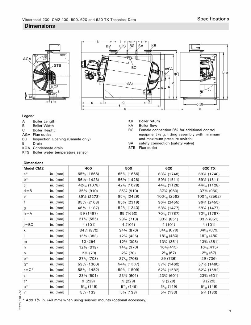
DimensionsSpecifications
LegendA Boiler LengthB Boiler WidthC Boiler HeightAGA Flue outletBO Inspection Opening (Canada only)E DrainKOA Condensate drainKTS Boiler water temperature sensor
KR Boiler returnKV Boiler flowRG Female connection Rb for additional control equipment (e.g. fitting assembly with minimum and maximum pressure switch)SA safety connection (safety valve)STB Flue outlet
* Add 1f in. (40 mm) when using seismic mounts (optional accessory).
8
5773 5
96 -
03
Vitocrossal 200, CM2 400, 500, 620 and 620 TX Technical Data
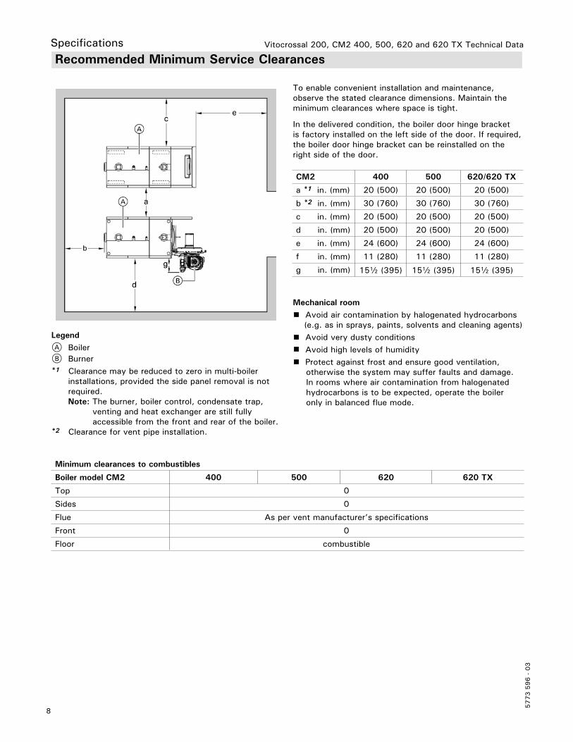
Recommended Minimum Service Clearances
Mechanical room Avoid air contamination by halogenated hydrocarbons
(e.g. as in sprays, paints, solvents and cleaning agents) Avoid very dusty conditions Avoid high levels of humidity Protect against frost and ensure good ventilation,
otherwise the system may suffer faults and damage. In rooms where air contamination from halogenated hydrocarbons is to be expected, operate the boiler only in balanced flue mode.
Minimum clearances to combustibles
Boiler model CM2 400 500 620 620 TX
Top 0
Sides 0
Flue As per vent manufacturer’s specifications
Front 0
Floor combustible
LegendA BoilerB Burner*1 Clearance may be reduced to zero in multi-boiler installations, provided the side panel removal is not required. Note: The burner, boiler control, condensate trap, venting and heat exchanger are still fully accessible from the front and rear of the boiler.*2 Clearance for vent pipe installation.
To enable convenient installation and maintenance, observe the stated clearance dimensions. Maintain the minimum clearances where space is tight.
In the delivered condition, the boiler door hinge bracket is factory installed on the left side of the door. If required, the boiler door hinge bracket can be reinstalled on the right side of the door.
CM2 400 500 620/620 TX
a *1 in. (mm) 20 (500) 20 (500) 20 (500)
b *2 in. (mm) 30 (760) 30 (760) 30 (760)
c in. (mm) 20 (500) 20 (500) 20 (500)
d in. (mm) 20 (500) 20 (500) 20 (500)
e in. (mm) 24 (600) 24 (600) 24 (600)
f in. (mm) 11 (280) 11 (280) 11 (280)
g in. (mm) 15b (395) 15b (395) 15b (395)
Specifications
9
5773 5
96 -
03
Vitocrossal 200, CM2 400, 500, 620 and 620 TX Technical Data Specifications
Flow Rate
Pressure drop (primary circuit)
The Vitocrossal 200 is only suitable for fully pumped hot water heating systems.
Recommended Flow Rates CM2
Boiler model 400 500 620 620 TX
20° F t GPM 137.2 171.0 213.2 198.9
40° F t GPM 68.6 85.5 106.6 95.0
11° C t m3/h 31.1 38.8 48.4 43.2
22° C t m3/h 15.5 19.4 24.2 21.6
t = temperature differenceThis boiler does not require a flow switch.
Pres
sure
dro
p
Flow rate
10
5773 5
96 -
03
Vitocrossal 200, CM2 400, 500, 620 and 620 TX Technical Data
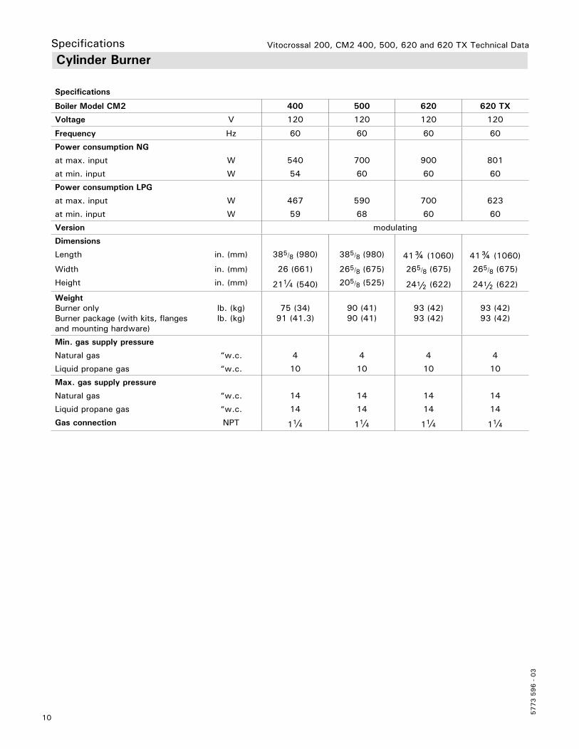
WeightBurner onlyBurner package (with kits, flanges and mounting hardware)
lb. (kg)lb. (kg)
75 (34)91 (41.3)
90 (41)90 (41)
93 (42)93 (42)
93 (42)93 (42)
Min. gas supply pressure
Natural gas “w.c. 4 4 4 4
Liquid propane gas “w.c. 10 10 10 10
Max. gas supply pressure
Natural gas “w.c. 14 14 14 14
Liquid propane gas “w.c. 14 14 14 14
Gas connection NPT 1a 1a 1a 1a
Specifications
11
5773 5
96 -
03
Vitocrossal 200, CM2 400, 500, 620 and 620 TX Technical Data Specifications Cylinder Radiant Burner (continued)
CM2 pre-mix cylinder burner 400/500/620/620 TX
LegendA Burner frameB Air pressure switch 1
C Air pressure switch 2D Display and programming unitE Gas valveF Gas supply pipeG Gas pressure switchH Rotary damper with servomotor (400, 620 and 620 TX only)I Gas pipe
J Manual shut-off valveK Venturi mixing pipeL Gas fanM Burner gauze assemblyN Ignition electrodesO Ionization electrodeP Ignition unitQ Burner control unitR Mains filter unit with contactor
CM2 Boiler model 400 500 620 620 TX
a in. (mm) 20 (506) 20 (506) 20 (506) 20 (506)
b in. (mm) 385/8 (980) 385/8 (980) 41c (1060) 41c (1060)
c in. (mm) 26 (661) 265/8 (675) 265/8 (675) 265/8 (675)
d in. (mm) 21a (540) 20f (525) 24b (622) 24b (622)
12
5773 5
96 -
03
Vitocrossal 200, CM2 400, 500, 620 and 620 TX Technical Data
Standard Equipment
Installation fittings for standard equipment includes:- low water cut-off - safety header (c/w 75 psig pressure relief valve, air vent and pressure gage)- drain valve- product documentation- combustion air intake kit- NG to LPG conversion kit
For multi-boiler system (up to 4 boilers) with Vitocontrol control panel
Vitotronic 300 (type GW5B) and LON module for modulating boiler water temperature for each boiler of the multi-boiler system and
without Vitocontrol control panel Vitotronic 300 (type GW5B) and LON module for modulating boiler water temperature in conjunction with an external control unit (BMS).
Vitocontrol-S, CM2 control panel with Vitotronic (300-K, type MW1B) for multi-boiler system, outdoor reset mode and mixing valve control for a maximum of 2 heating circuits with mixing valve and additional Vitotronic 200-H, type HK1B for 1 heating circuit with mixing valve.
For single boiler systems Vitotronic 300 (type GW5B)
Outdoor reset control for stand alone operation, for modulating water temperature with mixing valve (optional expansion board for two additional circuits).
Boiler Control Alternatives
CM2 Boiler model 400 500 620 620 TX
Thermal insulation 2 2 2 2
Cylinder burner 1 1 1 1
Boiler control unit (see boiler control alternatives below) 1 1 1 1
Boiler coding card 1 1 1 1
Technical documentation 2 2 2 2
Combustion air intake kit 1 1 1 1
Junction box 1 1 1 1
Boiler body with fitted mating ANSI flanges and gaskets to all connectors and fitted protective crate, plus flue gas collector collar.
Specifications
For single-boiler or multiple-boiler installationsCustom control panels for residential or commercial applications are designed and manufactured by Viessmann to suit any customer’s specific requirements. Custom control panels can integrate features such as pool heating, hot tub heating, snow melting, telephone tie-in, integration with Building Management Systems, as well as several other functions. Please inquire.
Boiler Accessories
Refer to the common venting flue vent damper Installation Instructions.
- Motorized flue gas damper (for cascade venting system)
13
5773 5
96 -
03
Vitocrossal 200, CM2 400, 500, 620 and 620 TX Technical Data Specifications System Design Considerations
Note: The ‘amount of condensate” and the “flue gas temperature gross” graphs are independent of each other.
Condensate and its disposalDuring the operation of the boiler, the amount of condensate to be expected can be read from the above diagram.The values given are approximate amounts occurring under practical conditions. Not included in the diagram is the amount of condensate occurring in the vent pipe and chimney system. The condensate from the chimney system can be collected together with the condensate from the heating boiler and be disposed of into a floor drain. The condensate will be between 3 and 4 on the pH scale. If local building requirements demand neutralizing the condensate before disposal, contact Viessmann Manufacturing Company Inc. for a correctly sized neutralization tank. The treated condensate will show pH values of between 6.5 and 9 and can then be disposed of into the waste water system.
Design notes regarding draining condensateThe condensate drain to the sewer connection must be able to be inspected.Route it with a gradient and equip the pipe with a P-trap; also provide suitable facilities for taking samples.The bottom drain should be located below the anti-flooding level of the flue gas collector box.
Condensate drains must only be made from corrosion resistant materials (e.g. fibre reinforced hoses). Never use any galvanized materials or those containing copper or black iron for pipes, connectors, etc.Install a P-trap in the condensate drain to prevent flue gases from escaping.
Venting options PP(s) (Polypropylene) flue gas/fresh air system for room air independent operation (sealed combustion), and PP(s) flue gas for room air dependent operation are tested to ANSI Z21.13 - CSA 4.9 - 2000 standards and are certified together with the Vitocrossal 200 boiler as a constructional unit.The Vitocrossal 200 boiler may also be vented using an special stainless steel, single-wall, (UL listed for category IV).
The boiler may be vented horizontally through the side wall or vertically through the roof.
For a more detailed description of the direct vent and single-wall vent system, please refer to the Vitocrossal 200 Installation Instructions venting section.
Use ULC S-636 / UL 1738 certified for category IV boilers. The following vent system suppliers may be contacted for assistance in designing the appropriate PP(s) venting system for Vitocrossal 200 CM2 boilers.
Burner adjustmentMartix cylinder burner tested at operating temperature and adjusted in the factory.
14
5773 5
96 -
03
Vitocrossal 200, CM2 400, 500, 620 and 620 TX Technical Data
System Design Considerations (continued)
System layoutThe boiler water temperature limit is factory set to 167° F (75° C).
The boiler water temperature limit can be increased by altering the adjustable high limit (AHL) to increase the supply water temperature.
To minimize piping losses of the system, however, Viessmann recommends that the radiation and domestic hot water production in the system be designed for a 158° F (70° C) boiler supply water temperature.
WarrantyOur warranty does not cover damages resulting from the following:- Operation with contaminated fill and supplementary feed water- Operation with contaminated combustion air- Exposing the boiler to pressures and temperatures higher than its certified rating
See warranty sheet for details.
Use ULC S-636 / UL 1738 certified venting systems for category IV boilers. The following vent system suppliers may be contacted for assistance in designing the appropriate stainless steel venting system for Vitocrossal 200 CM2 boilers.
Combustion air supplyThe boiler must not be located in areas or rooms where chemicals containing chlorine, bromine, fluorine, or other corrosive chemicals are stored. Examples include bleach, refrigerants, paint, paint thinner, hair spray, cleaning solvents, water softener salt, etc. The combustion air must not be contaminated with any amount of the above mentioned chemicals.
Boiler should never be installed in areas where excessive dust, high humidity, or risk of frost exist. Ensure adequate ventilation and supply of fresh combustion air.
Consult your local Viessmann sales representative with uncertainties in regard to a suitable boiler installation location.
This boiler/burner unit needs clean fresh air for safe operation. Provisions for combustion and ventilation air must be made at time of installation. For gas or propane installations, use the “Natural Gas Installation Code CAN/CSA-B149.1 or B149.2” (Canada), or “National Fuel Gas Code ANSI Z223.1” (USA), and/or provisions of local codes.
The sizing methods outlined in the aforementioned codes should be used when installing a round duct to supply combustion air from the outside.
Vitocrossal 200, CM2 400, 500, 620 and 620 TX Technical Data Specifications System Design Considerations (continued)
Airborne noise attenuationFrequently, modern boilers are equipped with silencer hoods or sound insulated ventilation air inlet housings.
For larger systems, it may be necessary to route the ventilation air through a sound-insulated channel, in order to avoid a noise nuisance outside the building.Flue gas silencers are generally only required where higher noise protection measures are called for. Whether or not a flue gas silencer is required can be predicted only with some difficulties, because of the complexity of the creation and propagation of flame noise, the interaction between the burner, boiler and the flue gas system as well as the operating mode (flue gas system operating with positive or negative pressure).
It is advisable, therefore, to assess the noise emission into the neighborhood and to consider the sound pressure level measured at the flue gas system outlet. It should be considered at the planning stage whether silencers might become necessary later.
In planning for its possible use, it is important that sufficient space for the flue gas silencer is available behind the boiler. Good engineering practice mandates that the exhaust pressure drop of the silencer be included in the vent size calculation.
Anti-vibration measuresAnti-vibration supports can be field supplied as an economical and effective solution to combat noise generated.When sizing such supports, take the entire operating weight of the boiler system and, when using longitudinal anti-vibration brackets, the condition of the supporting surface into consideration.
Effective anti-vibration measures are particularly important when installing boilers into an attic. Flexible couplings may be used to physically separate the combustion equipment from the building.
These should be installed into the boiler flow, return and safety pipe and as near as possible to the boiler.Also insulate any braces or hanging arrangements, if installed, against sound/vibration transmission to the building.
Water qualityTreatment for boiler feed water should be considered in areas with known problems, such as where a high mineral content and hardness exist. In areas where freezing might occur, it recommended that an antifreeze be added to the system water for protection against freezing. Please adhere to the specifications given by the antifreeze manufacturer. Do not use automotive silicate-based antifreeze. Please observe that an antifreeze/water mixture may require a back flow preventer within the automatic water feed and influence components such as diaphragm expansion tanks, radiation, etc. A 40% antifreeze content will provide freeze-up protection to -10° F (-23° C). Do not exceed 50% antifreeze mix ratio and do not use antifreeze other than specifically made for hot water heating systems.
Oxygen diffusion barrier under floor tubingThe boiler warranty does not cover pressure vessel failure resulting from corrosion caused by the use of underfloor plastic tubing without an oxygen diffusion barrier. Such systems without oxygen diffusion barrier must have the tubing separated from the boiler with a heat exchanger. Viessmann always recommends the use of underfloor plastic tubing with an oxygen diffusion barrier.
Boiler/burner start-upVitocrossal 200, CM2 boilers with Viessmann cylinder burners does not require start-up by Viessmann.
Sound attenuationPlease consult a professional engineer who is specialized in noise attenuation for advice.
The burner/boiler systems, circulation pumps and other auxiliary equipment used in heating systems generate noise.
This noise is transferred from the boiler room via floorboards, ceiling and walls to neighboring rooms and via the flue gas system as well as the ventilation air and exhaust air apertures into other rooms and into the open, where they may cause a nuisance.
To avoid this from happening, additional protective measures may be required which should be considered at the design stage.
Subsequent measures to reduce noise nuisance frequently require extensive effort and expenditure.
Total output (MBH) Total Hardness (ppm as ca CO3)
> 1 Total 680 200
> 680 to 2050 150
The pH value of the heating water should be between 8.2 and 9.5
5773 5
96 -
03
T
echn
ical
info
rmat
ion
subj
ect
to c
hang
e w
itho
ut n
otic
e.Pr
inte
d on
env
ironm
enta
lly f
riend
ly
(rec
ycle
d an
d re
cycl
able
) pa
per.
Vitocrossal 200, CM2 400, 500 and 620 Technical Data