+ All Categories
Home > Documents > 58504 temp controller kit instructions.pdf

58504 temp controller kit instructions.pdf

Date post: 01-Jun-2018
Category:
Upload: carlos-castillo-urrunaga
View: 235 times
Download: 2 times
Share this document with a friend
10
Page 1 of 10 Instructions for Service Kit 58504 Middleby Cooking Systems Group • 1400 Toastmaster Drive • Elgin, IL 60120 • USA • (847) 741-3 300 • FAX (847 ) 741-4406 KIT COMPONENTS Qt y . P/N Descr i p t i on  1 58388 Digital T emperature Controller (On/Off Gas & Electric, PID Gas, and V ariable Pulse Electric operating modes), with mounting brackets 1 58955 Instructions Middleby Cooking Systems Group • 1400 Toastmaster Drive Elgin, IL 60120 (847) 741-3300 FAX (847) 741-4406  P/N 58955 • Rev. B• V3 • 1/06 © 2002 Middleby Marshall. cjz TABLE OF CONTENTS Con troller Types ............................................................................................... 2 Before Y ou Begin ............................................................................................. 3 Installati on ........................................................................................................ 3 Elect rical Connections ..................................................................................... 4 Jumpe r Setti ng ................................................................................................. 6 Progr ammin g ................................................................................................... 6 Diagnos tic Err or Mess ages ............................................................................. 8 Operating Instructions (to be left with customer after installation) ...................... 9 Digital Temperature Controller Installation, Programming and T roubleshooting Instructions
Transcript

8/9/2019 58504 temp controller kit instructions.pdf

http://slidepdf.com/reader/full/58504-temp-controller-kit-instructionspdf 1/10

Page 1 of 10

Instructions for Service Kit 58504

Middleby Cooking Systems Group • 1400 Toastmaster Drive • Elgin, IL 60120 • USA • (847) 741-3300 • FAX (847) 741-4406

KIT COMPONENTS

Qty . P/N Desc rip tio n  

1  58388 Digital Temperature Controller (On/Off Gas & Electric, PID Gas, and

Variable Pulse Electric operating modes), with mounting brackets

1  58955 Instructions

Middleby Cooking Systems Group • 1400 Toastmaster Drive • Elgin, IL 60120

(847) 741-3300 • FAX (847) 741-4406


P/N 58955 • Rev. B• V3 • 1/06© 2002 Middleby Marshall. cjz

TABLE OF CONTENTS

Controller Types ...............................................................................................2

Before You Begin .............................................................................................3

Installation ........................................................................................................ 3

Electrical Connections ..................................................................................... 4

Jumper Setting .................................................................................................6

Programming ...................................................................................................6

Diagnostic Error Messages .............................................................................8

Operating Instructions (to be left with customer after installation) ...................... 9

Digital Temperature Controller Installation, Programming and Troubleshooting Instructions

8/9/2019 58504 temp controller kit instructions.pdf

http://slidepdf.com/reader/full/58504-temp-controller-kit-instructionspdf 2/10

Page 2 of 10

Controller Types

This Kit includes one Digital Temperature Controller (P/N 58388) that can operate at 120-240V, and

can be programmed to operate in on-off, PID, or variable pulse modes. The Controller is shown in

Figure 1G, below. By following these instructions, the Controller can be installed into any Middleby

Marshall oven equipped with the following Controllers.

• P/N 28071-0012 (Fig. 1A)

 Analog Temperature Controller without high-limit and

cooldown functions, operating at 120V, on-off mode only.

• P/N 28071-0018 (Fig. 1A)

 Analog Temperature Control ler with high-l imit and

cooldown functions, operating at 120V, on-off mode only.

• P/N 34983 (Fig. 1B)

 Analog Temperature Controller without high-limit and

cooldown functions, operating at 120V, on-off mode only.

Used on PS200VL models. As of 12/01, P/N 34983 is

still available and should be used on these ovens if 

 possible.

• P/N 28071-0027 (Fig. 1C)

Digital Temperature Controller with blue plastic face-plate, operating at 120V, on-off mode only.

• P/N 28071-0028 (Fig. 1D)

Digital Temperature Controller with gray rubber face-

plate and buttons with text, operating at 120V, on-off 

mode only.

• P/N 28071-0028 (Fig. 1E)

Digital Temperature Controller with gray rubber face

plate and buttons with symbols, operating at 120V, on-

off mode only.

• P/N 30871 (Fig. 1E)

Digital Temperature Controller with gray rubber face

plate and buttons with symbols, operating at 208-240V,

on-off mode only. Used on early PS360WB70 and some

CE oven models.

• P/N 32571 (Fig. 1E)

Digital Temperature Controller with gray rubber face

plate and buttons with symbols, operating at 208-240V,

PID mode only. Used on early PS360EWB.

• P/N 36021 (Fig. 1F)Digital Temperature Controller with gray face plate (steel

trim on edges), operating at 120-240V, selectable on-

off or PID modes.

• P/N 36056 (Fig. 1G)

Digital Temperature Controller with black plastic face

plate, operating at 120-240V, selectable on-off or PID

modes.

This Kit CANNOT be installed in a PS536 oven equipped with the P/N 44783 (variable pulse electric) or 

P/N 44823 (PID gas) controller shown below.

Figure 1

A B

C D E F G

H

8/9/2019 58504 temp controller kit instructions.pdf

http://slidepdf.com/reader/full/58504-temp-controller-kit-instructionspdf 3/10

Page 3 of 10

WARNING 

BEFORE PERFORMING ANY SERVICE WORK, THE ELECTRICAL POWER SUPPLY 

 AND THE GAS SUPPLY MUST BE TURNED OFF.

Before you Begin

1. This Temperature Controller requires a current-version thermocouple for proper operation. Check

that the thermocouple(s) installed in the oven match the current three-lead, flanged versions BE-FORE you begin to install the Temperature Controller. See Figure 2.

If the oven is not equipped with current thermocouples, you should replace them BEFORE you instal

the new Temperature Controller.

P/N 33984: Thermocouple kit for PS300-series, PS555 and PS570

P/N 33985: Thermocouple kit for PS200-series and PS536

flange

Figure 2

clip

Cable

(3 leads)

Cable

(2 leads)

Current thermocouple

Obsolete 2-lead

thermocouple

Installation

1. Access the back of the existing temperature controller. Tag each wire that connects to the controller 

with its terminal number. These numbers will be used later to wire the new controller.

2. Disconnect all wires from the terminals on the temperature controller. Be sure to retain any jumpers

that are removed.

3. Remove the controller and sleeve from the oven as follows:

• For analog controllers P/Ns 28071-0012 and 28071-0018 (Fig. 1A), remove the two bracket

screws on the back of the control. Then, remove the bracket. Pull the controller and sleeve out

through the front of the oven panel.

• For all other controllers, remove the two screws and brackets that hold the controller in place.

Then, pull the controller and sleeve out through the front of the panel.

8/9/2019 58504 temp controller kit instructions.pdf

http://slidepdf.com/reader/full/58504-temp-controller-kit-instructionspdf 4/10

8/9/2019 58504 temp controller kit instructions.pdf

http://slidepdf.com/reader/full/58504-temp-controller-kit-instructionspdf 5/10

Page 5 of 10

Figure 4a

 Analog temperature controller (P/Ns

28071-0012 and 28071-0018) terminals

New temperature

controller terminals

Not used. Theseterminals provide PID

output (gas ovens

with modulating

valve) or variable

Not used on

some gas and

electric ovens

Not used

Not used

 Analog temperature controller 

(P/N 34983) terminals

New temperature

controller terminals

Not used. PS200VL

ovens do not include a

modulating gas system

Not used. PS200VL

ovens have a sepa

rate high limit module

and do not include a

cooldown feature.

Not used

Not used

Figure 4b

pulse output (electric ovens with

variable pulse system). Neither of 

these systems were available with

ovens equipped with these

controllers.

Terminal for 

28071-0012 and Terminal for Terminal for Description

28071-0018 34983 46837

1 TC+ 8 + TC

2 TC- 7 - TC

5 COM 5 Input to Temperature Control Relay

6 NO 4 Output to High Flame Solenoid or Heater Contactors

L2 L2 L2 Neutral

L1 L1 L1 Power  

G G Ground

13 -- 9 Input to Cooldown Relay

14 -- 10 Output from Cooldown Relay

15 -- 11 Input to High Limit Relay

16 -- 12 Output from High Limit Relay

-- -- 15 PID or Variable Pulse Output

-- -- 16 PID or Variable Pulse Output

Figure 5aModulated Gas Output System

Figure 5bVariable Pulse Output System

 Amplifier boardModulating

valve

24VAC

input

4-20mA

input

0-24VDC

output

20VDC pulsed output

Relay

NOTE: Safety switches

may be placed between

the temperature controller 

and the relay on some

oven models.

NOTE: Controller P/N 32571 used Terminals 4 & 5

for the 4-20mA input to the amplifier board.

These connections must be moved to Terminals

15 & 16 on the new controller as shown.

8/9/2019 58504 temp controller kit instructions.pdf

http://slidepdf.com/reader/full/58504-temp-controller-kit-instructionspdf 6/10

Page 6 of 10

Jumper Setting

Loosen the Phillips screw at the bottom center of the faceplate. Then, pull the controller out of its sleeve.

Next, access the jumper shown in Figure 6. This jumper affects the signal that is output from Terminals15 and 16. The jumper MUST be set to the correct position for proper operation of the controller.

Figure 6

Jumper is set to the “W1”

position for gas ovens with

modulating gas system

Jumper is set to the “W2”

position for electric ovens

with variable pulse system

• For gas ovens equipped with the modulating gas system, For PS540 Electric & PS555Electric, the jumper must be set to the “W1” position.

This instructs the controller to send a variable-current 4-20 mA signal from Terminals 15 and 16 tothe amplifier board. The board converts this to a 0-24VDC signal which is sent to the modulatingvalve. The valve regulates the gas flow according to the need for heat to maintain the set point.

For gas ovens, you should always check inside the machinery compartment to see whether a modu-lating valve is present in the unit before setting this jumper.

• For electric ovens equipped with the variable pulse system, the jumper must be set to the“W2” position.

This instructs the controller to send a constant-current, pulsed 20VDC signal to the relay. Once everyfour seconds, the signal “pulses” on proportional to the need for heat to maintain the set point.

The PS536 Electric oven (as of 1/02), the PS520E & the Blodgett 1820S uses the variable pulsesystem. Other oven models equipped with this system will be announced by Middleby as they be-come available.

• For all other ovens - gas or electric - that use the on-off system, the jumper may be set toeither position.

C A U T I O N  

If the jumper is incorrectly set, the oven will be unable to properly maintain temperature. In addi-

tion, DAMAGE MAY OCCUR TO THE CONTROLLER AND OTHER OVEN COMPONENTS. Always make sure that the jumper is correctly set BEFORE restoring power to the oven! 

 After the jumper has been properly set, replace

the controller into its sleeve and tighten the screw.

Programming

1. Restore electrical power to the oven.

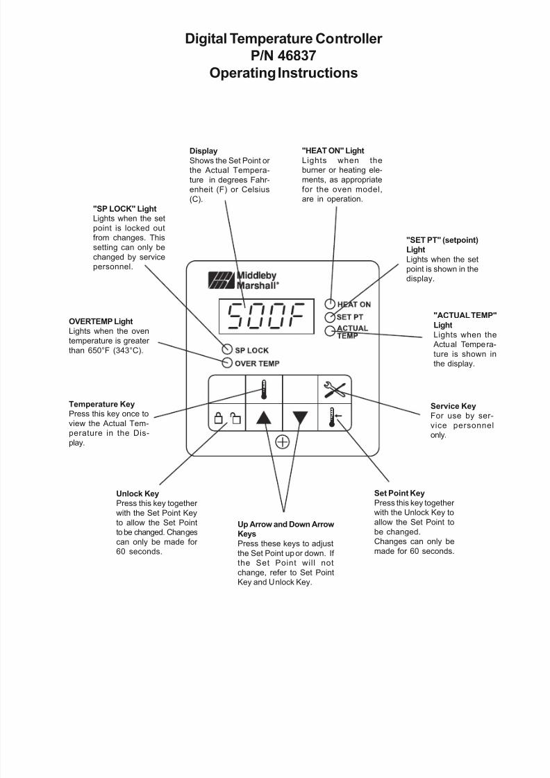
2. Refer to Figure 7. Set the following options,according to the customer’s preferences:

• Set Point locked or unlocked

• Degrees Fahrenheit or Celsius

• Set Point or Actual Temperature display

3. Set the controller to PID or On-Off operating

mode. Choose the PID mode for BOTH gasovens with the modulating system AND for elec-tric ovens with the variable pulse system.

4. Adjust the Set Point according to thecustomer’s specifications.

5. If the PID operating mode was chosen, per-form an Auto-Tune calibration as per the in-structions in Figure 7.

6. Check that the customer is familiar with theoperation of the controller. The last page of these instructions includes an operating guide

for the controller. Remove this page and leave

8/9/2019 58504 temp controller kit instructions.pdf

http://slidepdf.com/reader/full/58504-temp-controller-kit-instructionspdf 7/10

Page 7 of 10

   F   i  g  u  r  e   7

   T  e  m  p  e  r  a   t  u  r

  e   C  o  n   t  r  o   l   l  e  r   S  e  r  v   i  c  e   I  n  s   t  r  u  c

   t   i  o  n  s

8/9/2019 58504 temp controller kit instructions.pdf

http://slidepdf.com/reader/full/58504-temp-controller-kit-instructionspdf 8/10

Diagnostic Error Messages

The controller runs background tests during normal operation. If any problems occur during the tests, an

error message flashes in the display. A listing of these diagnostic error messages is shown below.

Flashes on the display (alter-

nating with the temperature)

indicating that the internal di-

agnostic test has failed.

The oven temperature hasnot reached 200°F/93°C

within 15 minutes of startup.

On gas ovens, this is usually

a result of the burner not light-

ing.

Caused by an open in the

thermocouple circuit.

Polarity of the thermocouple

leads is reversed.

1. Turn the Blower Switch (HEAT Switch for PS536 ovens with the two-

switch configuration) OFF for 2 minutes.

2. Turn the Blower Switch (or HEAT Switch, as per Step 1) ON.3. If necessary, repeat Steps 1 and 2 up to two additional times.

4. If the problem does not clear after 3 attempts, replace the controller.

1. Turn the Blower Switch (HEAT Switch for PS536 ovens with the two-

switch configuration) OFF for 2 minutes.

2. Turn the Blower Switch (or HEAT Switch, as per Step 1) ON.

3. If the problem does not clear, contact the Middleby Technical Ser-vice Department for assistance.

1. Check that the thermocouple leads are properly connected to Ter-

minals 7 & 8 of the temperature controller.

2. Check the continuity of the thermocouple at room temperature. Youshould measure 9-20 Ohms of resistance.

3. If the reading was outside the correct range, the thermocouple has

an open. Remove and replace the thermocouple.

If the reading was inside the correct range, contact the Middleby

Technical Service Department for assistance.

1. Check the polarity of the thermocouple leads. The red wire (-) should

be attached to Terminal 7 on the temperature controller. The white

wire (+) should be attached to Terminal 8.

2. If the polarity connections are incorrect, connect the thermocouple

properly.

If the polarity connections are correct, replace the thermocouple.

Page 8 of 10

8/9/2019 58504 temp controller kit instructions.pdf

http://slidepdf.com/reader/full/58504-temp-controller-kit-instructionspdf 9/10

Display

Shows the Set Point or 

the Actual Tempera-

ture in degrees Fahr-

enheit (F) or Celsius

(C).

"SP LOCK" Light

Lights when the set

point is locked out

from changes. This

setting can only be

changed by service

personnel.

OVERTEMP Light

Lights when the oven

temperature is greater 

than 650°F (343°C).

Temperature Key

Press this key once to

view the Actual Tem-

perature in the Dis-

play.

Unlock Key

Press this key together 

with the Set Point Key

to allow the Set Point

to be changed. Changes

can only be made for 60 seconds.

Up Arrow and Down Arrow

Keys

Press these keys to adjustthe Set Point up or down. If 

the Set Point will not

change, refer to Set Point

Key and Unlock Key.

Set Point Key

Press this key together 

with the Unlock Key to

allow the Set Point to

be changed.

Changes can only bemade for 60 seconds.

Service KeyFor use by ser-

vice personnel

only.

"ACTUAL TEMP"

Light

Lights when the

 Actual Tempera-

ture is shown in

the display.

"SET PT" (setpoint)

Light

Lights when the set

point is shown in thedisplay.

"HEAT ON" Light

Lights when the

burner or heating ele-

ments, as appropriate

for the oven model,

are in operation.

Digital Temperature Controller 

P/N 46837

Operating Instructions

8/9/2019 58504 temp controller kit instructions.pdf

http://slidepdf.com/reader/full/58504-temp-controller-kit-instructionspdf 10/10

Middleby Cooking Systems Group • 1400 Toastmaster Drive • Elgin, IL 60120(847) 741-3300 • FAX (847) 741-4406


Recommended