87
5D.Design AutoCAD Plugin Guide R2.6 November, 2010 M. Slegers, Crystal 5D Technologies Version: Date: Author:

5D.DesignAutoCAD Plugin
Guide
R2.6November, 2010M. Slegers, Crystal 5D Technologies
Version:Date:Author:

- 1 -
5D.Design AutoCAD Plugin Guide
Contents
1 AutoCAD Plugin Installation4
................................................................................................................................... 41.1 Install AutoCAD Plugin
....................................................................................................................................................................................... 41.1.1 Install Plugin
....................................................................................................................................................................................... 41.1.2 Configure AutoCAD
....................................................................................................................................................................................... 61.1.3 Configure Plugin
................................................................................................................................... 71.2 Install AutoCAD Library
....................................................................................................................................................................................... 71.2.1 Install Library
....................................................................................................................................................................................... 81.2.2 Install Drawings
....................................................................................................................................................................................... 81.2.3 Configure Project
2 Create 5D.Design Documents10
................................................................................................................................... 102.1 Export from 5D.Design
....................................................................................................................................................................................... 102.1.1 Export Facility Design
....................................................................................................................................................................................... 102.1.2 Export Tool Configuration
....................................................................................................................................................................................... 102.1.3 Export Section
....................................................................................................................................................................................... 112.1.4 Export View
....................................................................................................................................................................................... 112.1.5 Export Picture
................................................................................................................................... 112.2 Create AutoCAD Drawings
....................................................................................................................................................................................... 122.2.1 Create an Overall Drawing
....................................................................................................................................................................................... 132.2.2 Create all Overall Drawings
....................................................................................................................................................................................... 142.2.3 Create a Facility Drawing
....................................................................................................................................................................................... 172.2.4 Create all Facility Drawings
....................................................................................................................................................................................... 192.2.5 Create a Hookup Drawing
....................................................................................................................................................................................... 222.2.6 Create all Hookup Drawings
................................................................................................................................... 242.3 Settings
....................................................................................................................................................................................... 262.3.1 Options
....................................................................................................................................................................................... 272.3.2 Save
....................................................................................................................................................................................... 282.3.3 Search Paths
....................................................................................................................................................................................... 292.3.4 Layers
....................................................................................................................................................................................... 302.3.5 Scales and Texts
....................................................................................................................................................................................... 312.3.6 Paper
....................................................................................................................................................................................... 322.3.7 Attributes
...................................................................................................................................................... 332.3.7.1 Draw ing 1
...................................................................................................................................................... 342.3.7.2 Draw ing 2
...................................................................................................................................................... 352.3.7.3 Objects 1
...................................................................................................................................................... 362.3.7.4 Objects 2
....................................................................................................................................................................................... 362.3.8 Styles
...................................................................................................................................................... 372.3.8.1 General
...................................................................................................................................................... 382.3.8.2 Draw ing List
...................................................................................................................................................... 392.3.8.3 Schematic Draw ings
...................................................................................................................................................... 402.3.8.4 Data Sheets
...................................................................................................................................................... 412.3.8.5 Routing Plans
...................................................................................................................................................... 442.3.8.6 Isometric Draw ings
...................................................................................................................................................... 452.3.8.7 3D Draw ings
....................................................................................................................................................................................... 452.3.9 All Documents
...................................................................................................................................................... 472.3.9.1 Overall
...................................................................................................................................................... 482.3.9.2 Facility
...................................................................................................................................................... 492.3.9.3 Hookup

- 2 -
5D.Design AutoCAD Plugin Guide
................................................................................................................................... 492.4 Drawing Properties
....................................................................................................................................................................................... 492.4.1 Project Name
....................................................................................................................................................................................... 502.4.2 File Properties
................................................................................................................................... 512.5 Drawing Templates
....................................................................................................................................................................................... 512.5.1 Drawing Units
....................................................................................................................................................................................... 522.5.2 Text Styles, Dimension Styles and Line Types
....................................................................................................................................................................................... 522.5.3 Layers
....................................................................................................................................................................................... 522.5.4 Blocks and Symbols
....................................................................................................................................................................................... 522.5.5 Page Layout
................................................................................................................................... 532.6 Other Templates
....................................................................................................................................................................................... 532.6.1 General Notes
....................................................................................................................................................................................... 532.6.2 Keyed Notes
................................................................................................................................... 542.7 Blocks and Symbols
....................................................................................................................................................................................... 542.7.1 Blocks
....................................................................................................................................................................................... 542.7.2 Symbols
................................................................................................................................... 562.8 Macros
....................................................................................................................................................................................... 562.8.1 Create a Macro
....................................................................................................................................................................................... 582.8.2 Pre-defined Macro Functions
...................................................................................................................................................... 592.8.2.1 General Macro Functions
...................................................................................................................................................... 592.8.2.2 Object Macro Functions
...................................................................................................................................................... 602.8.2.3 Block Macro Functions
...................................................................................................................................................... 622.8.2.4 XRef Macro Functions
...................................................................................................................................................... 632.8.2.5 PaperSpace Macro Functions
...................................................................................................................................................... 632.8.2.6 Draw ing Macro Functions
3 Create 5D.Design Sections65
................................................................................................................................... 653.1 Export Sections from 5D.Design
................................................................................................................................... 653.2 Import Sections into AutoCAD
4 Export 5D.Design Layouts67
................................................................................................................................... 674.1 Export a Tool Layout from AutoCAD
................................................................................................................................... 674.2 Import a Tool Layout into 5D.Design
5 Create AutoCAD Library Blocks68
................................................................................................................................... 685.1 Export 2D Views from 5D.Design
................................................................................................................................... 685.2 Import 2D Views into AutoCAD
6 APPENDIX70
................................................................................................................................... 706.1 Drawings
....................................................................................................................................................................................... 706.1.1 Overall Drawings
....................................................................................................................................................................................... 716.1.2 Facility Drawings
....................................................................................................................................................................................... 726.1.3 Hookup Drawings
................................................................................................................................... 736.2 Variables
................................................................................................................................... 746.3 Symbols
....................................................................................................................................................................................... 746.3.1 General Symbols
....................................................................................................................................................................................... 756.3.2 Component Symbols
....................................................................................................................................................................................... 766.3.3 Symbol Labels
....................................................................................................................................................................................... 766.3.4 Attribute Blocks
....................................................................................................................................................................................... 786.3.5 Piping Symbols

- 3 -
5D.Design AutoCAD Plugin Guide
................................................................................................................................... 786.4 Object Types
................................................................................................................................... 786.5 Wildcards
................................................................................................................................... 796.6 Error Messages
....................................................................................................................................................................................... 796.6.1 Failed to open project from file
....................................................................................................................................................................................... 796.6.2 Do you want to save the changes...?
....................................................................................................................................................................................... 806.6.3 Drawing not saved!
................................................................................................................................... 816.7 Examples
....................................................................................................................................................................................... 816.7.1 Schematic Examples
....................................................................................................................................................................................... 826.7.2 Routing Examples
Index 85

- 4 -
5D.Design AutoCAD Plugin Guide
1 AutoCAD Plugin Installation
1.1 Install AutoCAD Plugin
1.1.1 Install Plugin
AutoCAD and VBA
To use the AutoCAD plugin, you need AutoCAD 2004 or higher installed.
From AutoCAD 2010, VBA is no longer part of the default AutoCAD installation. Because the VBA module isneeded to run the AutoCAD plugin, it must be downloaded and installed separately.
See the Autodesk website for more information.
Run installer
Execute the Plugin installer. For example:Crystal.5D.AutoCAD.Plugin.v2.6.0.0.exe
By default, the plugin is installed on your system:C:\Program Files\Crystal Interactive\AutoCAD.Plugin\
but you can define any drive or folder, for example on a server:\\MyServer\Crystal InterActive\AutoCAD.Plugin\
1.1.2 Configure AutoCAD
Add VBA Folder
Add VBA folder to the Support File Search Path settings:
In AutoCAD menu, choose Tools Options
Go to tab Files
Select Support File Search Path
Add the VBA folder: <plugin folder>\VBA

- 5 -
5D.Design AutoCAD Plugin Guide
Select OK
Load Menu
Load the Crystal menu:
In the AutoCAD command line type:menuload
Select Browse...
Select the cui file: <plugin folder>\Support\Crystal.cui

- 6 -
5D.Design AutoCAD Plugin Guide
Select Load
Select OK
The Crystal Menu will be loaded and ready for use.
1.1.3 Configure Plugin
The AutoCAD plugin is automatically registered when installing it on your PC.If you did not install the plugin yourself, but want to run the plugin from a server, you need to register the plugin.
Register AutoCAD plugin
Register the plugin and define the search folder for new updates:
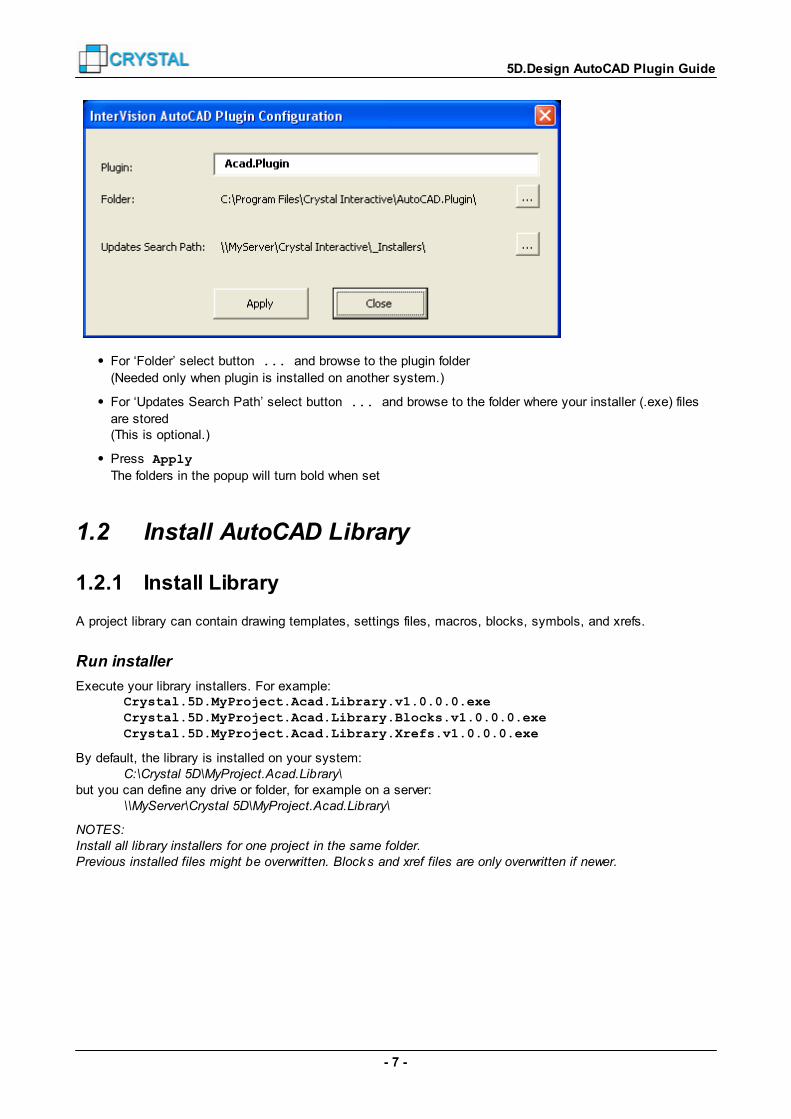
In AutoCAD menu, choose Crystal InterVision Settings Configure AutoCADPlugin
- 7 -
5D.Design AutoCAD Plugin Guide
For ‘Folder’ select button ... and browse to the plugin folder
(Needed only when plugin is installed on another system.)
For ‘Updates Search Path’ select button ... and browse to the folder where your installer (.exe) files
are stored(This is optional.)
Press Apply
The folders in the popup will turn bold when set
1.2 Install AutoCAD Library
1.2.1 Install Library
A project library can contain drawing templates, settings files, macros, blocks, symbols, and xrefs.
Run installer
Execute your library installers. For example:Crystal.5D.MyProject.Acad.Library.v1.0.0.0.exeCrystal.5D.MyProject.Acad.Library.Blocks.v1.0.0.0.exeCrystal.5D.MyProject.Acad.Library.Xrefs.v1.0.0.0.exe
By default, the library is installed on your system:C:\Crystal 5D\MyProject.Acad.Library\
but you can define any drive or folder, for example on a server:\\MyServer\Crystal 5D\MyProject.Acad.Library\
NOTES:Install all library installers for one project in the same folder.Previous installed files might be overwritten. Blocks and xref files are only overwritten if newer.

- 8 -
5D.Design AutoCAD Plugin Guide
1.2.2 Install Drawings
The drawings installer contains example AutoCAD drawings for your project.
Run installer
Execute your drawing installers. For example:Crystal.5D.MyProject.Acad.Drawings.Overall.v2.5.0.0.exeCrystal.5D.MyProject.Acad.Drawings.MyConfiguration.v2.5.0.0.exe
By default, the example drawings are installed on your system:C:\Crystal 5D\MyProject.Acad.Drawings\
but you can define any drive or folder, for example on a server:\\MyServer\Crystal 5D\MyProject.Acad.Drawings\
1.2.3 Configure Project
The project library and the example drawings are automatically registered when installing them on your PC.If you did not install the project library yourself, but want to use library files from a server, you need to registerthe project.
Register your project
Register a project and define the search folder for new updates
In AutoCAD menu, choose Crystal InterVision Settings Configure Projects

- 9 -
5D.Design AutoCAD Plugin Guide
For ‘Project name’, select your projectNote: only projects that are used and registered for 5D.Design are listed.Default names for the Library and the drawings are set automatically.
For ‘AutoCAD Library’, define the registered library nameSelect ... and browse to the library folder
(Needed only when library is installed on another system.)
For ‘AutoCAD Drawings’, define the registered library nameSelect ... and browse to the drawings folder
(Needed only when drawings are installed on another system.)
Press Apply
The folders in the popup will turn bold when set

- 10 -
5D.Design AutoCAD Plugin Guide
2 Create 5D.Design Documents
2.1 Export from 5D.Design
2.1.1 Export Facility Design
Export an xml file to create overall plans and facility documents:
In 5D.Design, export via function: File Export CAD Basebuild and Process Layout
If you need to create only a few drawings, for example because of revisions, choose to:
A. Export only the architectural part (to create Overall Building plans and Overall Architectural plans): File Export CAD Architecture
B. Export the process layout only (to create Overall Tool Configuration plans): File Export CAD Process Layout
C. Export all facility configurations only (to create Overall Facility Tool plans, Overall Distribution plans, orFacility documents): File Export CAD Facilities All Facility Systems
D. Export one facility configuration (to create Facility documents): File Export CAD Facilities Facility <name> only
2.1.2 Export Tool Configuration
Export an xml file to create hookup documents:
In 5D.Design, export tool configuration via menu function: File Export CAD Hookup Configuration <Name> only
or an xml file for all tool configurations: File Export CAD Hookup All configurations
2.1.3 Export Section
Export sections, used to create custom Overall drawings:
In 5D.Design, create a cross section from menu function: File Export Cross Section At Pickpoint
For a top view, define your point about eye level (about 1500mm or 60” above floor level),and choose view direction -Z.
Note: Do not create the section exactly at floor level. Then you will not get proper results.
Check ‘include building’ and uncheck ‘include design’.
Save the sectionSave in the same folder as your exported design.

- 11 -
5D.Design AutoCAD Plugin Guide
If the section is used to create overall drawings, the file name has to start with “OV_”, or with the projectname plus an underscore (“_”).Syntax:
OV_<level>.xsect <projectName>_<level>.xsect
2.1.4 Export View
Export views, used to create custom Hookup drawings:
In 5D.Design, select a tool or pipe from a hookup configuration
Create a cross section from menu function: File Export Cross Section Configuration
Define your view direction.
Save the section and backgroundSave in the same folder as your exported design or tool configuration.
If the view will be used to create a facility or hookup drawing, the file name has to start with the facility or toolconfiguration name plus an underscore (“_”).Syntax:
<facilityName>_<viewName>.xsect <configurationName>_<viewName>.xsect
2.1.5 Export Picture
Export pictures, used to create custom Facility and Hookup drawings:
In 5D.Design, press “Camera” on the bottom left of the Crystal 5D.Design window.
This creates a screenshot of the current view.
Save the pictureSave in the same folder as your exported design or tool configurations.
If the view will be used to create a facility or hookup drawing, the file name has to start with the facility or toolconfiguration name plus an underscore (“_”).Syntax:
<facilityName>_<pictureName>.jpg <configurationName>_<pictureName>.jpg
2.2 Create AutoCAD Drawings
You can create:
An overall drawing
Multiple overall drawings
A facility drawing
Multiple facility drawings
A hookup drawing
Multiple hookup drawings
12
13
14
17
19
22
- 12 -
5D.Design AutoCAD Plugin Guide
2.2.1 Create an Overall Drawing
Start the plugin:
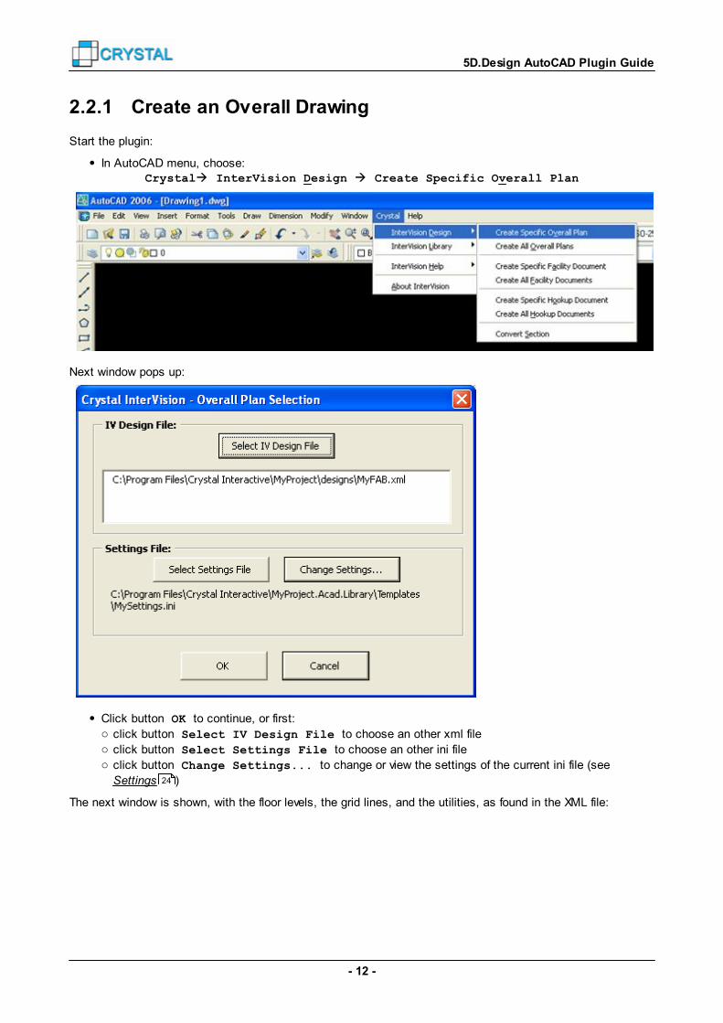
In AutoCAD menu, choose: Crystal InterVision Design Create Specific Overall Plan
Next window pops up:
Click button OK to continue, or first:o click button Select IV Design File to choose an other xml fileo click button Select Settings File to choose an other ini fileo click button Change Settings... to change or view the settings of the current ini file (see
Settings )
The next window is shown, with the floor levels, the grid lines, and the utilities, as found in the XML file:
24

- 13 -
5D.Design AutoCAD Plugin Guide
Choose the drawing you want to create:
o Select a Drawing Group (for example “Architectural”)
o Select a Drawing Area or Level (for example “30 Fab_Floor”)
o Optional select Utilities
Press OK to create the drawing.
After the drawing is generated, press Save to save it with the default name.
For the drawing names, see Options .For the save path of the drawings, see Search Paths .See Overall Drawings for a list of drawings.
Abort generating the drawing with key press Ctrl+Break.
2.2.2 Create all Overall Drawings
Start the plugin:
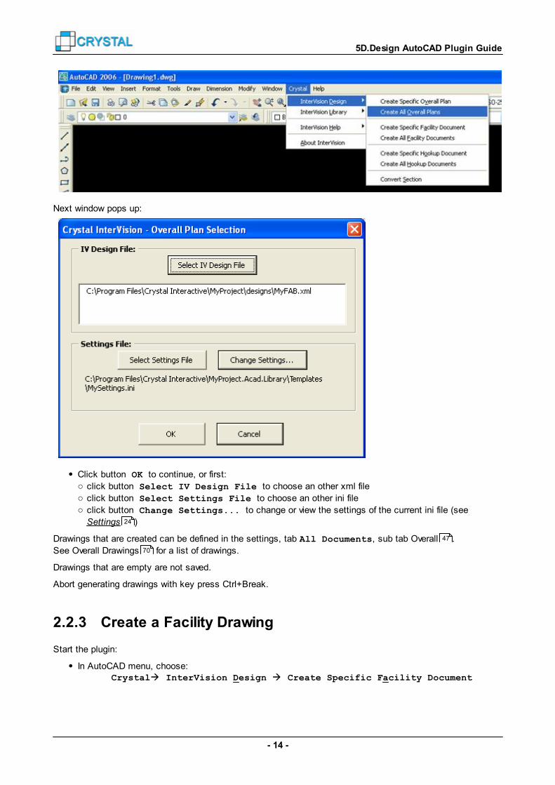
In AutoCAD menu, choose: Crystal InterVision Design Create All Overall Plans
26
28
70
- 14 -
5D.Design AutoCAD Plugin Guide
Next window pops up:
Click button OK to continue, or first:o click button Select IV Design File to choose an other xml fileo click button Select Settings File to choose an other ini fileo click button Change Settings... to change or view the settings of the current ini file (see
Settings )
Drawings that are created can be defined in the settings, tab All Documents, sub tab Overall .
See Overall Drawings for a list of drawings.
Drawings that are empty are not saved.
Abort generating drawings with key press Ctrl+Break.
2.2.3 Create a Facility Drawing
Start the plugin:
In AutoCAD menu, choose: Crystal InterVision Design Create Specific Facility Document
24
47
70

- 15 -
5D.Design AutoCAD Plugin Guide
Next window pops up:
Click button OK to continue, or first:o click button Select IV Design File to choose an other xml fileo click button Select Settings File to choose an other ini fileo click button Change Settings... to change or view the settings of the current ini file (see
Settings )
If the xml contains more than one facility configuration, a window with all facility configuration names pops up:
24

- 16 -
5D.Design AutoCAD Plugin Guide
Select one or more facility systems. (Hold Shift or Ctrl to select multiple systems.)
Check Merge selected facilities to draw all selected facilities in one drawing.
Uncheck when you want to create a drawing per facility.If checked, define the facility-group name.
Press OK to continue.
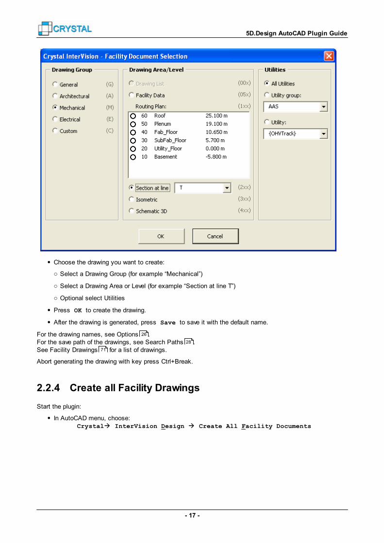
The next window is shown, with the floor levels, the grid lines, and the utilities, as found in the XML file:
- 17 -
5D.Design AutoCAD Plugin Guide
Choose the drawing you want to create:
o Select a Drawing Group (for example “Mechanical”)
o Select a Drawing Area or Level (for example “Section at line T”)
o Optional select Utilities
Press OK to create the drawing.
After the drawing is generated, press Save to save it with the default name.
For the drawing names, see Options .For the save path of the drawings, see Search Paths .See Facility Drawings for a list of drawings.
Abort generating the drawing with key press Ctrl+Break.
2.2.4 Create all Facility Drawings
Start the plugin:
In AutoCAD menu, choose: Crystal InterVision Design Create All Facility Documents
26
28
71

- 18 -
5D.Design AutoCAD Plugin Guide
Next window pops up:
Click button OK to continue, or first:o click button Select IV Design File to choose an other xml fileo click button Select Settings File to choose an other ini fileo click button Change Settings... to change or view the settings of the current ini file (see
Settings )
If the xml contains more than one facility configuration, a window with all facility configuration names pops up:
24

- 19 -
5D.Design AutoCAD Plugin Guide
Select one or more facility systems. (Hold Shift or Ctrl to select multiple systems.)
Check Merge selected facilities to draw all selected facilities in one drawing.
Uncheck when you want to create a drawing per facility.If checked, define the facility-group name.
Press OK to continue.
Drawings that are created can be defined in the settings, tab All Documents, sub tab Facility .
See Facility Drawings for a list of drawings.
Drawings that are empty are not saved.
Abort generating drawings with key press Ctrl+Break.
2.2.5 Create a Hookup Drawing
Start the plugin:
In AutoCAD menu, choose: Crystal InterVision Design Create Specific Hookup Document
48
71

- 20 -
5D.Design AutoCAD Plugin Guide
Next window pops up:
Click button OK to continue, or first:o click button Select IV Design File to choose an other xml fileo click button Select Settings File to choose an other ini fileo click button Change Settings... to change or view the settings of the current ini file (see
Settings )
If the xml contains more than one tool configuration, a window with all tool configuration names pops up:
24

- 21 -
5D.Design AutoCAD Plugin Guide
Select one or more hookup configurations. (Hold Shift or Ctrl to select multiple systems.)
Press OK to continue.
The next window is shown, with the floor levels, and the utilities, as found in the XML file:

- 22 -
5D.Design AutoCAD Plugin Guide
Choose the drawing you want to create:
o Select a Drawing Group (for example “Electrical”)
o Select a Drawing Area or Level (for example “20 SubFab_Floor”)
o Optional select Utilities
Press OK to create the drawing.
After the drawing is generated, press Save to save it with the default name.
For the drawing names, see Options .For the save path of the drawings, see Search Paths .See Hookup Drawings for a list of drawings.
Abort generating the drawing with key press Ctrl+Break.
2.2.6 Create all Hookup Drawings
Start the plugin:
In AutoCAD menu, choose: Crystal InterVision Design Create All Hookup Documents
26
28
72

- 23 -
5D.Design AutoCAD Plugin Guide
Next window pops up:
Click button OK to continue, or first:o click button Select IV Design File to choose an other xml fileo click button Select Settings File to choose an other ini fileo click button Change Settings... to change or view the settings of the current ini file (see
Settings )
If the xml contains more than one tool configuration, a window with the tool configuration names pops up:
24
- 24 -
5D.Design AutoCAD Plugin Guide
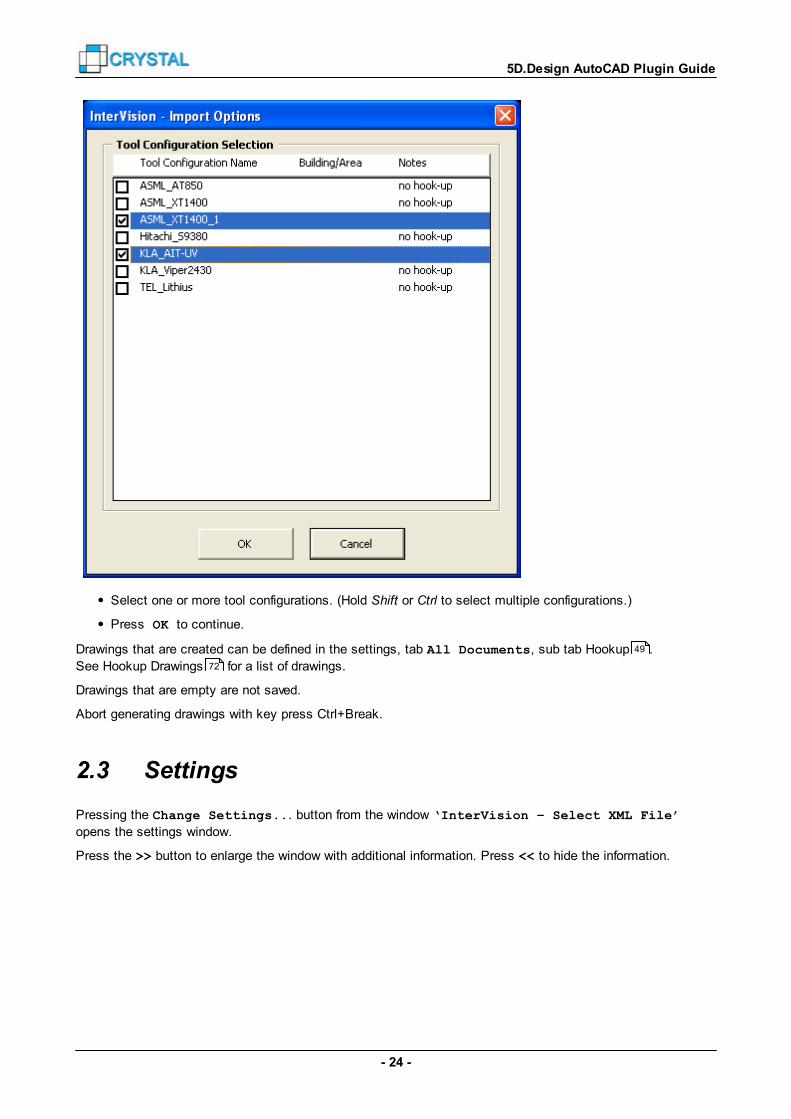
Select one or more tool configurations. (Hold Shift or Ctrl to select multiple configurations.)
Press OK to continue.
Drawings that are created can be defined in the settings, tab All Documents, sub tab Hookup .
See Hookup Drawings for a list of drawings.
Drawings that are empty are not saved.
Abort generating drawings with key press Ctrl+Break.
2.3 Settings
Pressing the Change Settings... button from the window ‘InterVision – Select XML File’
opens the settings window.
Press the >> button to enlarge the window with additional information. Press << to hide the information.
49
72
- 25 -
5D.Design AutoCAD Plugin Guide
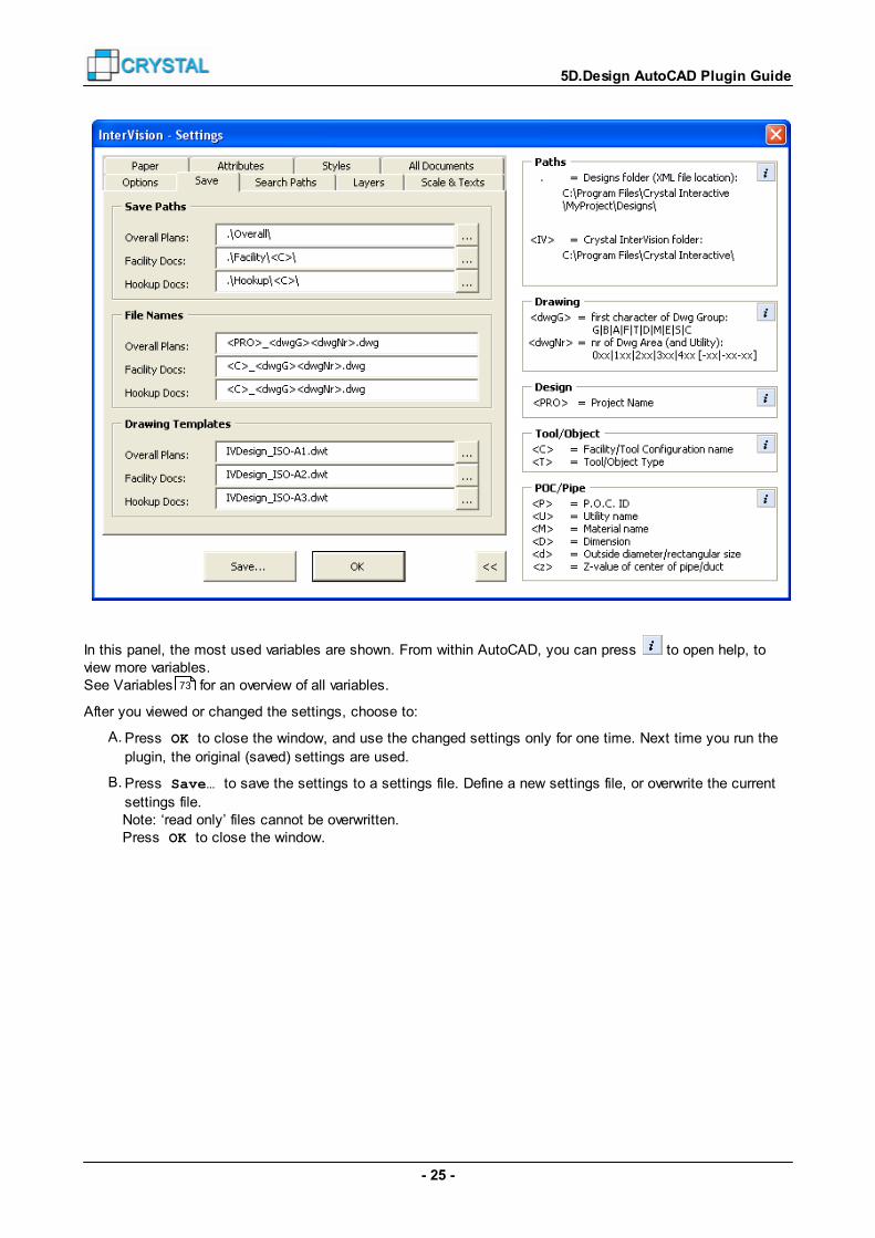
In this panel, the most used variables are shown. From within AutoCAD, you can press to open help, toview more variables.See Variables for an overview of all variables.
After you viewed or changed the settings, choose to:
A. Press OK to close the window, and use the changed settings only for one time. Next time you run the
plugin, the original (saved) settings are used.
B. Press Save… to save the settings to a settings file. Define a new settings file, or overwrite the current
settings file.Note: ‘read only’ files cannot be overwritten.Press OK to close the window.
73
- 26 -
5D.Design AutoCAD Plugin Guide
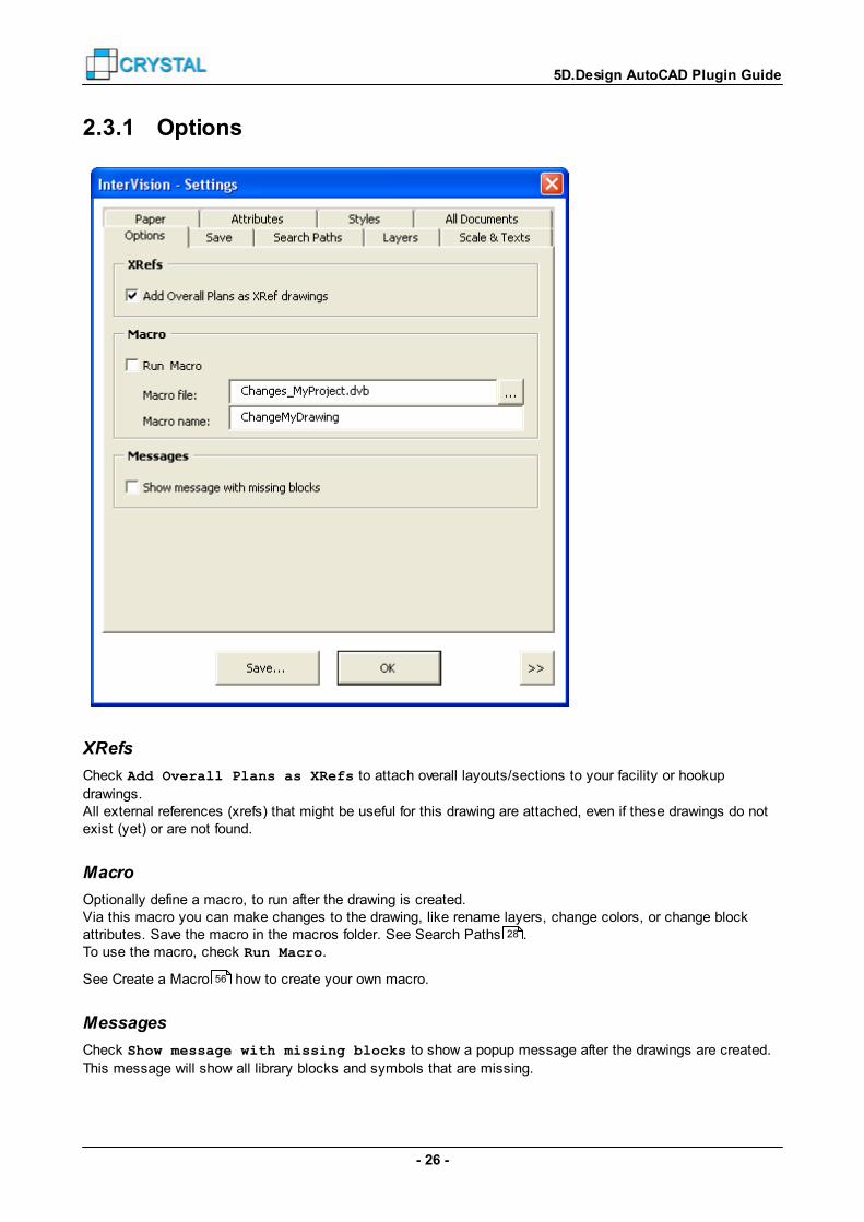
2.3.1 Options
XRefs
Check Add Overall Plans as XRefs to attach overall layouts/sections to your facility or hookup
drawings.All external references (xrefs) that might be useful for this drawing are attached, even if these drawings do notexist (yet) or are not found.
Macro
Optionally define a macro, to run after the drawing is created.Via this macro you can make changes to the drawing, like rename layers, change colors, or change blockattributes. Save the macro in the macros folder. See Search Paths .To use the macro, check Run Macro.
See Create a Macro how to create your own macro.
Messages
Check Show message with missing blocks to show a popup message after the drawings are created.
This message will show all library blocks and symbols that are missing.
28
56

- 27 -
5D.Design AutoCAD Plugin Guide
When a library block is missing, it is not skipped, but this block is added in the drawing as a rectangularobject.
2.3.2 Save
Save Paths
Define the folder names to save the drawings that will be generated.Use variables like a dot (.) to define a save path relative to the used xml file, or <C> to use the configurationname.
File Names
Define the file name for overall plans, facility documents, and hookup documents.Use variables like <C>. Use the drawing variable (“<dwgG><dwgNr>”) in the filename for the best results.
For example:Coded File Name Example drawing file name:<PRO>_<dwgG><dwgNr>.dwg DemoFAB_T130.dwg<C>_<dwgG><dwgNr>.dwg TRK400_M120.dwg

- 28 -
5D.Design AutoCAD Plugin Guide
Drawing Templates
Define the drawing template files to use.
For more information, see Drawing Templates .
2.3.3 Search Paths
The plugin will search for drawing templates, macros, blocks and symbol blocks in the next folders:1. user defined search paths;2. project library folders;3. standard library folders;4. plugin folders
Blocks and symbol blocks are also searched for in sub folders.
User Defined Search Paths
Optionally define search paths for drawing templates, macros, blocks and symbol blocks.
Use variables like <IV>.Define multiple search paths, separated by a semi-colon (“;”).
51

- 29 -
5D.Design AutoCAD Plugin Guide
AutoCAD Libraries
Define the Project AutoCAD Library to use.You can choose only from registered libraries, named *AcadLibrary. The paths for that library are used.To define multiple libraries, use a semi-colon (“;”) as separator.
Optionally define the Standard AutoCAD Library to use.You can choose only from registered libraries, named *StandardAcadLibrary. The paths for that library areused.To define multiple libraries, use a semi-colon (“;”) as separator.
2.3.4 Layers
Layer Names
Define layer names for different kinds of objects.Use variables like <U> for the utility or <T> for the tool or object type.

- 30 -
5D.Design AutoCAD Plugin Guide
2.3.5 Scales and Texts
Drawing Scale
Define the viewport scales for the layouts, sections, etc.
The Drawing List, Schematic drawings and Data Sheets, always have scale 1:1.When isometric or 3D drawings do not fit on paper, they are scaled to fit.
See Paper to optionally rescale a drawing that does not fit on paper.
Text Styles and Heights
Define the text styles to use for standard texts, titles and subtitles.Define you own text styles in the drawing template. For more information, see Drawing Templates .If any of the text styles does not exist in the drawing template, the plugin creates a default textstyle.
Define the text heights for the three different text styles.In PaperSpace, these text heights are used. In ModelSpace, the height is multiplied by the drawing scalefactor, to match the correct size in PaperSpace.The units of the design file are used. For example: set Standard text height to 2.5 for millimeters, or to 0.1 forinches.
31
51

- 31 -
5D.Design AutoCAD Plugin Guide
Dimension Styles
Define the dimension styles to use.Define your own dimension style in the drawing template. For more information, see Drawing Templates .
2.3.6 Paper
Text Field
When Add key Plan is checked, the defined key plan will be inserted in the top of the text field. For plan
layouts only.It will be scaled to fit in the text field.This key plan must have the same origin as the 5D.Design, but must be scaled 1/1000. The keyplan issearched for in the Symbols folder. To use different key plans for the floor levels, define the name as forexample ‘keyplan<L>.dwg’.
When Add Key Plan Mark is checked, a mark will be inserted on this key plan, at the position of the tool
configuration. (For hookup configuration drawings only.)
When Add Notes is checked, lists of general and keyed notes are created, and inserted in the text field.
Define your own general and keyed notes. See General Notes and Keyed Notes .
51
53 53

- 32 -
5D.Design AutoCAD Plugin Guide
When Add Legend is checked, a legend is created and added in the text field.
Optionally include utilities.
When Add Scale Icon is checked, a scale bar will be inserted in the bottom of the text field.
See Page Layout how to define the text field area.
Drawing Field
When Add Compass is checked, an arrow is added in one of the corners of the drawing field. For isometric
and 3D drawings only.The symbol block ‘G-NORTH.dwg’ is used. If you do not wish to use the default symbol, create your ownsymbol, and place it in the ‘Symbols’ folder. You must use the same file name.See also Symbols , item General Symbols.
See Page Layout how to define the drawing field area.
Zoom Drawing
When a drawing not fits on one page, using the defined drawing scale, choose to:Do nothing – you will see only a part of the drawing in PaperSpace.Create multiple sheets – multiple sheets are created, and labels (block G-SHEET.dwg) are drawn that referto the connecting sheet number. (For plans and sections only),Re-scale the drawing to fit – another drawing scale is used to show the complete drawing in PaperSpace.
If ‘rescale text’ is checked, the texts and the labels are scaled to match the PaperSpace text height.Add overview sheet – a second sheet is created, with another drawing scale is to show the completedrawing in PaperSpace. (For plans and sections only).
Optionally match the zoom positions for drawings. Then, the zoom center for different floor levels or sectionswill on the same location.
The views can be rotated 90 degrees. (For plans only.)
Optionally clip xrefs to the drawing extents, or to the drawing field.Grid and/or level labels are added at the edges of the clipping plane.
Extra Sheets
Optionally add an extra sheet with the Datum Point Detail. For process tools in Hookup Architectural Plansonly.
Sheet Name
Rename the drawing sheet to: the drawing code (f.e. 'M120'), orthe drawing title (f.e. 'SubFab_Floor').
2.3.7 Attributes
You can define attributes:
Pre-defined attributes for objects in PaperSpace
User-defined attributes for objects in PaperSpace
Pre-defined attributes for objects in ModelSpace
User-defined attributes for objects in ModelSpace
52
54
52
33
34
35
36
- 33 -
5D.Design AutoCAD Plugin Guide
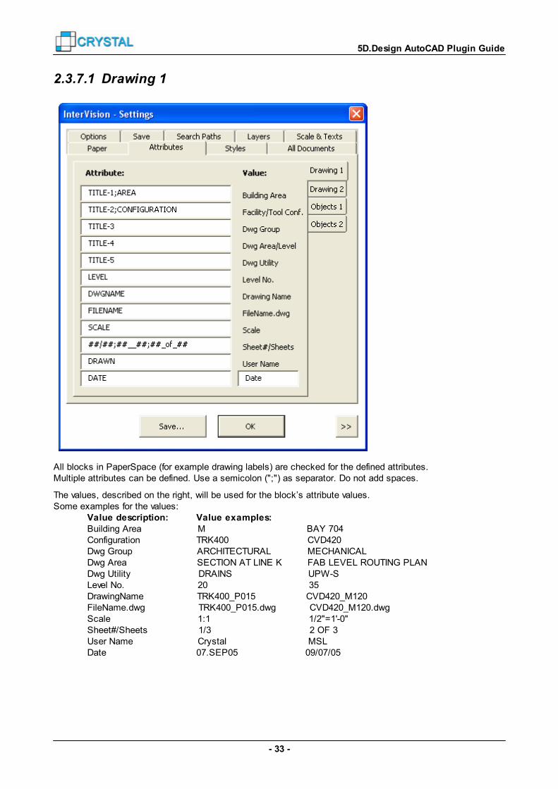
2.3.7.1 Drawing 1
All blocks in PaperSpace (for example drawing labels) are checked for the defined attributes.Multiple attributes can be defined. Use a semicolon (";") as separator. Do not add spaces.
The values, described on the right, will be used for the block’s attribute values.Some examples for the values:
Value description: Value examples:Building Area M BAY 704Configuration TRK400 CVD420Dwg Group ARCHITECTURAL MECHANICALDwg Area SECTION AT LINE K FAB LEVEL ROUTING PLANDwg Utility DRAINS UPW-SLevel No. 20 35DrawingName TRK400_P015 CVD420_M120FileName.dwg TRK400_P015.dwg CVD420_M120.dwgScale 1:1 1/2"=1'-0"Sheet#/Sheets 1/3 2 OF 3User Name Crystal MSLDate 07.SEP05 09/07/05

- 34 -
5D.Design AutoCAD Plugin Guide
If the attribute for 'Sheet#/Sheets' is like "##*##" then the text between "##" and "##" is used in the final text.Underscores ("_") are replaced by spaces (" "). For example:
Attribute: Value examples:##/## 1/3##_OF_## 2 OF 5SHEET 1/4
For the value for 'User Name', your user account name is used.
The value for the date can be a user-defined format expression. Some examples:Date description: Value examples:Date 09/07/05 *dddd, mmmm d, yyyy Wednesday, September 7, 2005mm/dd/yy 09/07/05d-m-yyyy 7-9-2005dd.mmmyy 07.Sep05DD.MMMYY 07.SEP05
* The Short Date as defined in your 'Regional and Language Options'.
2.3.7.2 Drawing 2
All blocks in PaperSpace (for example drawing labels) are checked for the defined attributes.Multiple attributes can be defined. Use a semicolon (";") as separator. Do not add spaces.

- 35 -
5D.Design AutoCAD Plugin Guide
The values in the column on the right will be used.Use variables like <C>.
2.3.7.3 Objects 1
All blocks in ModelSpace are checked for the defined attributes.Multiple attributes can be defined. Use a semicolon (";") as separator. Do not add spaces.
The values, described on the right, will be used for the block’s attribute values.
Some examples for the values:Value description: Value examples:Facility/Tool Conf. EXHAUST TRK400Name FRC_Panel Endura_ACBoxDisplay name P015 TRK400.B1POC ID 28 083Part No 216 GUtility PCW UPW-SMaterial FLEX SSDiameter DN 50 2 1/2"

- 36 -
5D.Design AutoCAD Plugin Guide
2.3.7.4 Objects 2
All blocks in ModelSpace are checked for the defined attributes.Multiple attributes can be defined. Use a semicolon (";") as separator. Do not add spaces.
The values in the column on the right will be used.Use variables like <C>, or variables to get POC data (if defined in the 5D Design) like <d:Capacity>.
2.3.8 Styles
You can define the drawing style for:
General settings
Drawing list
Schematic drawings
Data sheets
Routing plans
Isometric drawings
3D drawings
37
38
39
40
41
44
45

- 37 -
5D.Design AutoCAD Plugin Guide
2.3.8.1 General
System Grid
When a grid is drawn, labels are placed on the top and the right of the grid lines.Block ‘G-GRID.dwg’ is used from the symbols folder.Choose to draw the grid labels:
on the grid linesbetween the grid lines.
Utilities
Define the colors to use for the piping layers. default colorAutoCAD Index Color (ACI), nearest to color in 5D Designcolor in 5D Design, as True Color (RGB)
See Layers for default layer colors.52
- 38 -
5D.Design AutoCAD Plugin Guide
POC / Takeoff ID
Define the minimal number of digits for the POC and takeoff IDs. Some examples:
Minimal number of digits: IDs:1 8 242 08 243 008 024
Dimension
Define the sign to place in front of diameter texts.
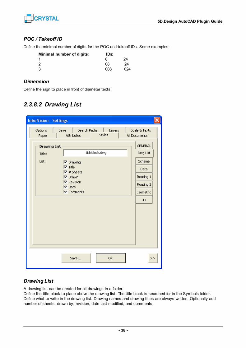
2.3.8.2 Drawing List
Drawing List
A drawing list can be created for all drawings in a folder.Define the title block to place above the drawing list. The title block is searched for in the Symbols folder.Define what to write in the drawing list. Drawing names and drawing titles are always written. Optionally addnumber of sheets, drawn by, revision, date last modified, and comments.

- 39 -
5D.Design AutoCAD Plugin Guide
2.3.8.3 Schematic Drawings
For some examples with different settings, see Schematic Examples .
Drawing
By default, the pipes and/or cables are drawn. If you have raceways and/or conduits defined in your 5D design,choose to draw your schematic drawing with raceways/conduits, instead of pipes/cables. With this optionchecked, POCs are grouped if possible.
By default, levels are drawn as a horizontal lines and horizontal texts on the right of the page. Optionally drawvertical texts on the left of the page.
Pipe
Define the line width for the pipes, and define if the pipe attributes are centered to the pipe.
Tools / POCs / Components
Choose an insertion point for the tool attributes.
By default, only the POC ID is visible. Optionally show all other POC attributes as well.By default the takeoffs are drawn above/under the corresponding POC. Optionally draw all takeoffs on the left ofthe page.
81

- 40 -
5D.Design AutoCAD Plugin Guide
Optionally ignore components that have no symbol block defined, and/or ignore elbows.
2.3.8.4 Data Sheets
Table Header Block
By default, headers for the tables are created by the plugin. Data for the header row is taken from the CAD-export file, and a default table title is written above it.The title text will be any of:
“OBJECT DATA”"TOOL DATA""MECHANICAL FACILITY SERVICE DATA - " & Facility/Tool Configuration Name"ELECTRICAL FACILITY SERVICE DATA - " & Facility/Tool Configuration Name"RACEWAY/BOX SECTION MATRIX"
You can define your own header block to use instead of this default header and title.Create a drawing for this table header just as you like: add lines, texts, logo, text styles, colors, etc. Keep thefile in your Symbols folder. This block will be scaled by the Standard Text Height (see Scales and Texts )when inserted in your drawing.If the block has an attribute ‘HD’, the default table title is used as its value.
When you use a header block, you of course have to define the column widths as well.
30

- 41 -
5D.Design AutoCAD Plugin Guide
Table Column widths
By default, the column widths will match the largest text in that column. This can cause different columnwidths every time you create such drawing.By default, texts are aligned on the left.
Instead of this default, you can define fixed column widths and text alignments.If no column width is defined, a column width is used to fit the texts for the column. If no alignment is defined,the text is aligned to the left.Define “L” or nothing for left, “C” for center, “R” for right, or “F” for fit alignment.
Some examples: 18;30;20;20;20;15;15
20L;L;C;R;120L;;;;;;150C
These column widths are multiplied by the Standard Text Height (see Scales and Texts ).
2.3.8.5 Routing Plans
For some examples with different settings, see Routing Examples .
30
82

- 42 -
5D.Design AutoCAD Plugin Guide
Tool
Choose to insert a tool block or an outline block (for hookup drawings only).Choose an insertion point for the tool attributes. The attributes block will be added only if the tool block doesnot already contain attributes.
POC and Takeoff
Define if you want POC and Takeoff labels in plans and/or sections for Facility and Hookup drawings.
Option to draw P.O.C. and takeoff labels with, or without the label symbol.POC labels are placed near the POC position, with a leader.
Uncheck Draw takeoff groups if you do not want the takeoffs to be drawn.
In routing plans, POC label blocks are always drawn with a leader. Optionally uncheck Add leader (to
takeoff label) to place the takeoff block object exactly above the takeoff base object.
Check Dimension takeoffs (facilities) if you want dimension lines between the takeoffs on a
header/branch.
Pipe
Define a line width for the pipes. This is used for schematic and facility/hookup routing.Optionally draw thin pipes as single lines, instead of double lines with a centerline, if the diameter of the pipe issmaller than defined value (in inches).
- 43 -
5D.Design AutoCAD Plugin Guide
Choose to draw the centerline, with a defined color and line type.Optionally add the pipe slope direction. (Symbol ‘G-SLOPE’.)Optionally add a text on the middle of the pipe. (Symbol ‘TXT_PIPE’.) By default, this block has attribute‘PIPETEXT’, and the default value for ‘PIPETEXT’ is ‘Z = <z>’.Optionally add labels where the pipe goes through the floor. (Symbol ‘ATT_PIPE’.) Pipe labels are alwaysplaced at the start point or end point of the pipe, when the pipe start and end point both do not refer to a POCor takeoff label.Optionally add dimension lines from the pipes to the nearest grid line or floor level.
Component
Define to draw the components in the routing plan as:a block from the blocks library (top/bottom/front/rear/left/right view). If not found, a box is drawn.a box (optionally with a symbol block).a pipe piece
Optionally skip components in vertical pipes.
Typical
A Typical is a group of component objects and pipe parts.
Optionally draw typicals that are underneath a raised floor, always as box. If not checked, the components andthe pipe parts are all drawn.

- 44 -
5D.Design AutoCAD Plugin Guide
2.3.8.6 Isometric Drawings
Pipe
Define a line width for the pipes.
Location
Optionally add XYZ point information to a POC (symbol ‘G-POINT’), or measure the POC to the nearest gridpoint.
Labels
Define the labels to add in the drawings.
Component
Define if you want to draw a typical as a box. If unchecked, all parts of the typical (pipes and components) aredrawn.

- 45 -
5D.Design AutoCAD Plugin Guide
Bill Of Material
Define the location of the bill of material. This can be in the text field, or in any corner of the drawing field.
2.3.8.7 3D Drawings
Views
Optionally create one 3D view (south-east view) or create four 3D views.
2.3.9 All Documents
You can define the drawings to generate for:
Overall plans
Facility drawings
Hookup drawings
In tab ‘*MORE*‘, define your cross sections to generate, and define if you want to split drawings per utility
47
48
49
- 46 -
5D.Design AutoCAD Plugin Guide
group.
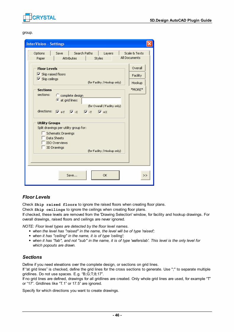
Floor Levels
Check Skip raised floors to ignore the raised floors when creating floor plans.
Check Skip ceilings to ignore the ceilings when creating floor plans.
If checked, these levels are removed from the 'Drawing Selection' window, for facility and hookup drawings. Foroverall drawings, raised floors and ceilings are never ignored.
NOTE: Floor level types are detected by the floor level names.when the level has "raised" in the name, the level will be of type 'raised';when it has "ceiling" in the name, it is of type 'ceiling';when it has "fab", and not "sub" in the name, it is of type 'waferslab '. This level is the only level forwhich popouts are drawn.
Sections
Define if you need elevations over the complete design, or sections on grid lines.If “at grid lines” is checked, define the grid lines for the cross sections to generate. Use ";" to separate multiplegridlines. Do not use spaces. E.g. “B;G;T;8;17”.If no grid lines are defined, drawings for all gridlines are created. Only whole grid lines are used, for example “T”or “17”. Gridlines like “T.1” or 17.5” are ignored.
Specify for which directions you want to create drawings.

- 47 -
5D.Design AutoCAD Plugin Guide
Utility Groups
Define what types of drawings need one drawing per utility group.For facility and hookup drawings only.
2.3.9.1 Overall
These settings are used when creating multiple overall drawings from AutoCAD menu: Crystal InterVision Design Create All Overall Plans
See tab *MORE* to define the cross sections to generate.
Note that you need Sections (.xsect files) to create Custom drawings.See Export Section how to create sections.
See Overall Drawings for a list of drawings.
10
70
- 48 -
5D.Design AutoCAD Plugin Guide
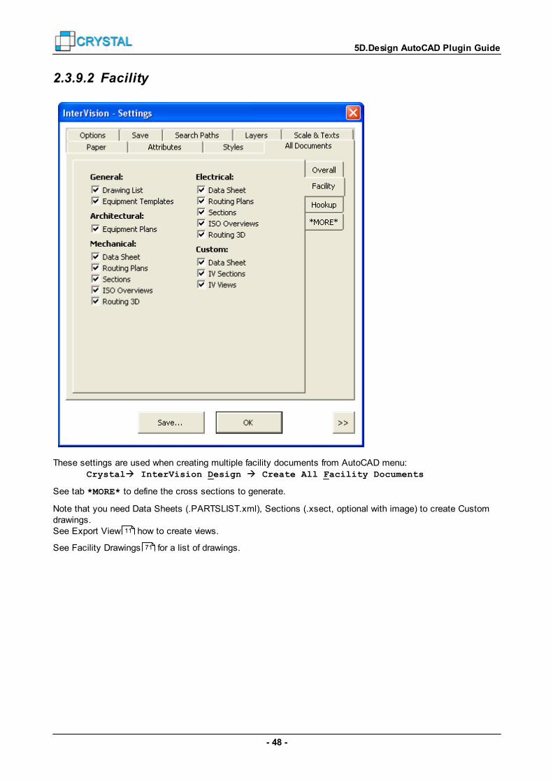
2.3.9.2 Facility
These settings are used when creating multiple facility documents from AutoCAD menu: Crystal InterVision Design Create All Facility Documents
See tab *MORE* to define the cross sections to generate.
Note that you need Data Sheets (.PARTSLIST.xml), Sections (.xsect, optional with image) to create Customdrawings.See Export View how to create views.
See Facility Drawings for a list of drawings.
11
71
- 49 -
5D.Design AutoCAD Plugin Guide
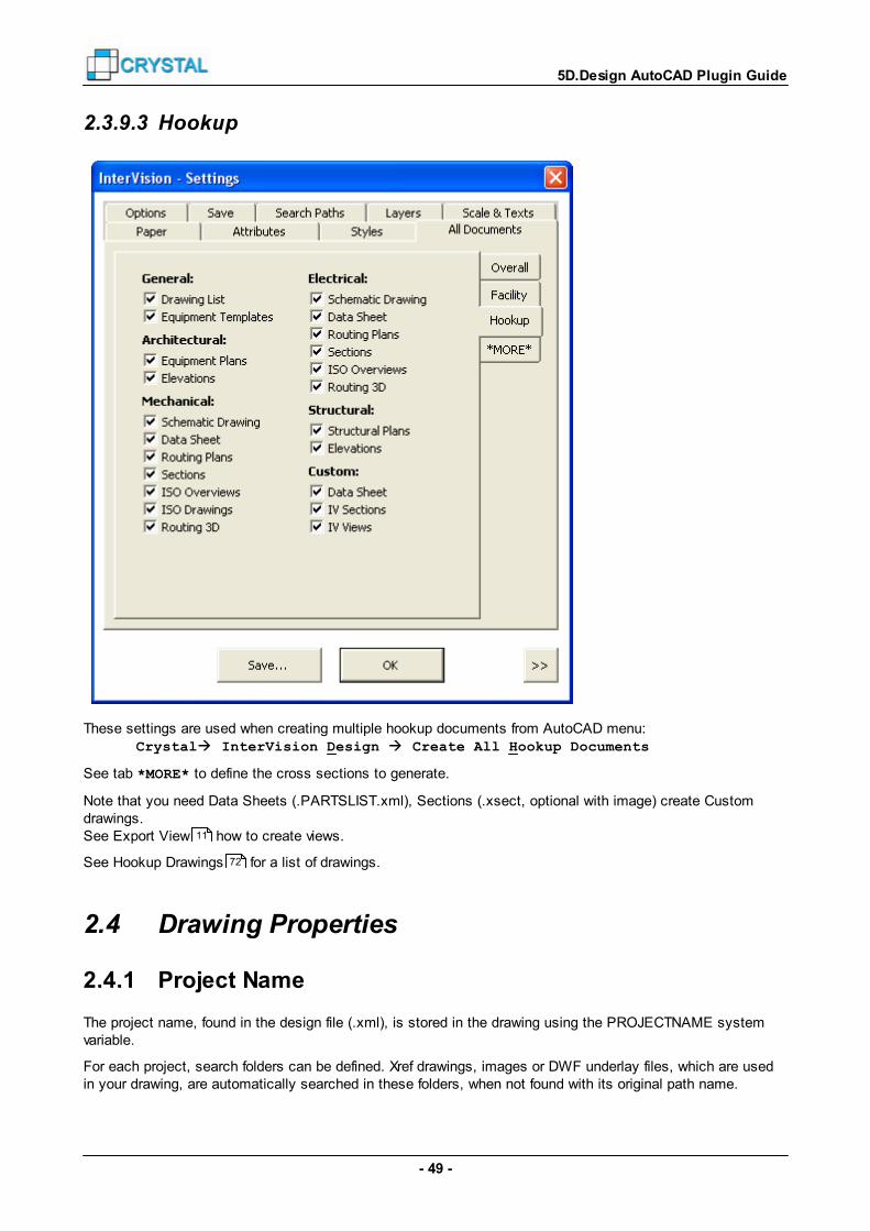
2.3.9.3 Hookup
These settings are used when creating multiple hookup documents from AutoCAD menu: Crystal InterVision Design Create All Hookup Documents
See tab *MORE* to define the cross sections to generate.
Note that you need Data Sheets (.PARTSLIST.xml), Sections (.xsect, optional with image) create Customdrawings.See Export View how to create views.
See Hookup Drawings for a list of drawings.
2.4 Drawing Properties
2.4.1 Project Name
The project name, found in the design file (.xml), is stored in the drawing using the PROJECTNAME systemvariable.
For each project, search folders can be defined. Xref drawings, images or DWF underlay files, which are usedin your drawing, are automatically searched in these folders, when not found with its original path name.
11
72

- 50 -
5D.Design AutoCAD Plugin Guide
Some paths for registered projects are added automatically by the plugin.
For more information about system variable ‘PROJECTNAME’ and ‘Project Files Search Paths’, see AutoCADHelp.
2.4.2 File Properties
For each overall, facility, or hookup drawing, properties are added to the drawing file.Some of these drawing properties are used when creating a drawing list. So, be careful when changing theseproperties.
View or edit drawing properties in AutoCAD from menu function File Drawing Properties...
or view them from Windows Explorer by right-click the file and select Properties.

- 51 -
5D.Design AutoCAD Plugin Guide
2.5 Drawing Templates
A drawing template (.dwt file) is used to create your Overall Plan, Facility Document or Hookup Document.The templates that will be used, and the search folders for the template files, are defined in the settings. See Save and Search Paths .
In the drawing template, you can define:
Drawing units
Text styles
Dimension styles
Line types
Layers
Blocks and symbols
Page layout
2.5.1 Drawing Units
Define your drawing units: for example mm, m, inches or feet.The drawing is always created in mm or inches. This is defined in the Design file (.xml file).
To change the drawing units, in AutoCAD menu: Format Units… Insertion Scale
27 28
51
52
52
52
52
52
52

- 52 -
5D.Design AutoCAD Plugin Guide
2.5.2 Text Styles, Dimension Styles and Line Types
Pre-define the textstyles for the standard, title and sub-title texts.The text heights must be 0.0. The heights are defined in your settings. See Scales and Texts .
Define a dimension style.It must be created as for scale 1:1. The overall scale is used to scale the dimension object in ModelSpace..
Needed line types are created when running the plugin.If you wish to use an other line type than the default line type for the center line of the pipe, add a new line typeto the drawing template, and define the line type in the settings (see Routing Plans ).
Unused text styles, dimension styles and line types are purged after creating the drawing.
2.5.3 Layers
Layers are created when running the plugin.See Layers for the layer names.
Pre-define the layers in the drawing template. Then colors, line types, etc. will not be changed. The layersmust be unlocked and thawed.
If the layers do not exist in the drawing template, the layer is created on demand.By default, next colors are used when layers are created by the plugin:
For routing in facility/hookup drawings: 10, 11, 20, 21, 30, 31, 40, 41…240, 241For routing in overall drawings: 12, 13, 22, 23, 32, 33, 42, 43…242, 243For tools in facility/hookup drawings: 14, 24, 34, 44… 244For tools in overall drawings: 16, 26, 36, 46… 246
Instead of using the default colors for routing, use the colors as in 5D.Design.See General to change to 5D.Design colors.
Unused layers are purged after creating the drawing.
2.5.4 Blocks and Symbols
You can add blocks and symbols to the drawing template.If needed, they are used from the drawing and not searched in the blocks folder or symbols folder. For thesearch paths of blocks and symbols, see Search Paths .
Unused blocks are purged after creating the drawing.
2.5.5 Page Layout
Paper Size and Plot Settings
Define your own paper size and plot settings.
Paper layout
Define your own paper layout. Add for example a drawing frame and a drawing label.When running the plugin, all attributes of all blocks in PaperSpace are filled in with values as defined in thesettings. See Attributes .
30
41
29
37
28
32

- 53 -
5D.Design AutoCAD Plugin Guide
View port
You have to use exactly one view port.
Drawing Field and Text Field
Layers "_DRAWINGFIELD" and "_TEXTFIELD" with lines, rectangles, etc. define the sizes of the text field andthe drawing field.The drawing field usually corresponds with the view port. The text field defines the area where a key plan,notes, legends, etc. will be drawn.You must not change these layer names.
These objects are removed, and the layers are purged after creating the drawing.
Sheet Layouts
Use only one sheet layout.When the plugin is running, multiple sheet layouts may be created as copies of the first sheet.The names of the sheet will be changed according to the drawing code or drawing name. See Paper .
2.6 Other Templates
2.6.1 General Notes
Create a text file ‘GeneralNotes.txt’ to define your own general notes, which will be added to each facility orhookup drawing, based on its drawing code.Save the text file in the templates folder. See Search Paths .
In this text file, define each note, predefined with the drawing code between curly brackets ({}).See Facility Drawings and Hookup Drawings for the drawing codes. Use wildcards to define the drawingcode. See Wildcards .
For example:
{A13*} TEMPORARY WALLS WILL BE REQUIRED FOR BULKHEAD TOOL INSTALLATION.
{A13*} ALL FLOORTILE CUTS SHALL HAVE EDGE PROTECTION, EDGE PROTECTION SHALL BE CUTIN SECTIONS NO LARGER THAN THE WIDTH OF FLOOR TILE TO ALLOW SINGLE TILEREMOVAL. INSTALL WITH MICRO-CONTAMINATION APPROVED, DOUBLE-SIDED TAPE.
{A[12]*} ARCHITECTURAL CONTRACTOR SHALL PROVIDE (FURNISH AND INSTALL) ALLARCHITECTURAL COMPONENTS AND MATERIAL UNLESS NOTED OTHERWISE.
{M[01]*} MECHANICAL CONTRACTOR SHALL PROVIDE (FURNISH AND INSTALL) ALL MECHANICALCOMPONENTS AND MATERIALS UNLESS OTHERWISE INDICATED.
{E0[01234]*} ELECTRICAL CONTRACTOR SHALL PROVIDE (FURNISH AND INSTALL) ALL ELECTRICALCOMPONENTS AND MATERIALS UNLESS OTHERWISE INDICATED.
2.6.2 Keyed Notes
Create a text file ‘KeyedNotes.txt’ to define your own text for the keyed notes.Save the text file in the templates folder. See Search Paths .
In this text file, define each note, predefined with the drawing code between curly brackets ({}), and the note ID,also between curly brackets. You must not change the drawing code and the note ID; but you can change the
31
28
71 72
78
28
- 54 -
5D.Design AutoCAD Plugin Guide
note text.See Facility Drawings and Hookup Drawings for the drawing codes. Use wildcards to define the drawingcode. See Wildcards .
For example:
{A1*} {1} SCOPE OF WORK
{A1*} {2} TOOL PIVOT
{A1*} {3} REMOTE TOOL PIVOT
{A1*} {4} RACK PIVOT
{A1*} {6} EQUIPMENT BOUNDARY (EB)
{A1*} {8} OHV CENTERLINE
{A1*} {9} VIEW TILE
When you do not define the notes, texts as in above example are used by default.
2.7 Blocks and Symbols
2.7.1 Blocks
The used blocks folder is defined in the settings. See Search Paths .
Object views
For all library objects, next types of blocks can exist:top view <object name>.dwgbottom view <object name>_bottom.dwgleft view <object name>_left.dwgright view <object name>_right.dwgfront view <object name>_front.dwgrear view <object name>_rear.dwgoutline <object name>_outline.dwg
2.7.2 Symbols
The used symbol blocks folders are defined in the settings. See Search Paths .
This folder and its subfolders contain next types of symbol blocks:project specific blocksgeneral symbolstool symbolscomponent symbolslabelsattributespiping symbols
When inserted in the drawing, most of the symbol blocks are resized to match the defined text height, andscaled according the used drawing scale.
The symbols can be changed, according to your needs.Except for the component symbols, you must use the same file name.
71 72
78
28
28
- 55 -
5D.Design AutoCAD Plugin Guide
Create as much as new component symbols as you need.
Project Specific Blocks
Specific blocks for a project are for example a logo and a key plan.The key plan must have the same origin as the 5D.Design, but must be scaled 1/1000.
General Symbols
The symbols need a size that suits with a text height of 1 unit. The blocks will be resized in the drawing tomatch the defined text height, and drawing scale.
The scale icons (G-SCALE and G-SCALE1) must be 10 units wide.
See General Symbols for a list of default general symbols.
Tool Symbols
Tool symbols can be used in schematic drawings.When a tool block is not found in the project library, it is not used.
The blocks will be resized in the drawing to match the defined text height, and are scaled to the used drawingscale.
Component Symbols
The blocks will be resized in the drawing to match the defined text height, and are scaled to the used drawingscale.
When used in schematic drawings, they are added to a legend. In this legend the symbol block is inserted,and a description. When the symbol block does have a constant attribute "DESCRIPTION", that value is used.When no “DESCRIPTION” attribute is defined, the block name is used as description. The attribute“DESCRIPTION” can be invisible.
See Component Symbols for a list of default general symbols.
Labels
Label blocks are used as annotation blocks for leader objects.
When inserted in the drawing, the symbol blocks are resized to match the defined text height, and scaled tothe used drawing scale.
See Symbol Labels for a list of default label blocks.
Attributes
Attribute blocks are added to blocks (only if they do not have attributes yet) or to component symbols.Attribute blocks are in general drawings that contain only attributes.
When inserted in the drawing, the symbol blocks are resized to match the defined text height, and scaled tothe used drawing scale.
See Attribute Blocks for list of default attribute blocks.
Piping Symbols
The blocks for round and rectangular pipe are created for diameters of 1.0 unit, or rectangles of 1.0x1.0 units.They will be scaled in the drawing to match the actual diameter or width and height.
- 56 -
5D.Design AutoCAD Plugin Guide
The blocks for cables need a size that suits with a text height of 1 unit. They will be resized in the drawing tomatch the defined text height, and are scaled to the used drawing scale.
See Piping Symbols for a list of default general symbols.
2.8 Macros
2.8.1 Create a Macro
Create a new macro
In AutoCAD menu, choose Tools Macro VBA Manager...
Click button New
Click button Visual Basic Editor
Change macro name
Open the properties window: In menu, choose View Properties Window
Select your macro in the project explorer. By default, the project name is 'ACADProject'.
Change the macro name in the properties window to for example: 'ChangeDrawing_MyProject'.
Add reference file
Pre-defined macro functions are saved in macro ‘IV_DrawingChanges‘ that comes with the plugin installer.These functions can be used when you are not familiar with building macros from scratch.This vba file needs to be referenced to your macro, to use the functions.
In AutoCAD menu, choose Tools Macro Macros...
Click button VBA Manager
Click button Load...
Select '<plugin folder>\VBA\IV_DrawingChanges.dvb'
Click button Visual Basic Editor
Check if your macro is still active in the project explorer.
Click button Tools References...
Check 'IV_DrawingChanges'

- 57 -
5D.Design AutoCAD Plugin Guide
Press OK
Edit macro
Double click 'Thisdrawing' in 'AutoCAD Objects' in your macro.
How to create macros in VBA is not explained further here.
You can use pre-defined functions from the referenced macro, as described in next paragraphs.
Save macro
Click button File Save Global?
Define your file name. For example '<project library folder>\Macros\Changes_MyProject.dvb'
Load an existing macro
Instead of starting from scratch, use a copy from the macro that came with the plugin installer.
In AutoCAD menu, choose Tools Macro VBA Manager...
Click button Load...
Select the macro to load and click button Open
Click button Visual Basic Editor
See next image for an impression of the Visual Basic Editor.

- 58 -
5D.Design AutoCAD Plugin Guide
2.8.2 Pre-defined Macro Functions
Pre-defined macro functions are saved in macro ‘IV_DrawingChanges‘ that comes with the plugin installer.These functions can be used when you are not familiar with building macros from scratch.This vba file needs to be referenced to your macro, to use the functions.
The pre-defined macro functions are divided in the next categories:
General Macro Functions
Object Macro Functions
Block Macro Functions
XRef Macro Functions
59
59
60
62

- 59 -
5D.Design AutoCAD Plugin Guide
PaperSpace Macro Functions
Drawing Macro Functions
You can add “IV_DrawingChanges.” in front of the function, but it is not needed. Next two lines for example areboth valid: IV_DrawingChanges.AddLayer "Util_UPW", 123
AddLayer "Util_UPW", 123
2.8.2.1 General Macro Functions
GetDrawingProperties
Reads the properties of the current drawing, and fills variables with the drawing propertiesthat can be used forIF-THEN statements.
Syntax: GetDrawingProperties
Next variables are filled: DwgProject
DwgBuildingDwgAreaIVTypeIVDwgCodeIVConfig
Example of using the variables:
If IVDwgCode = “A120” Then … ElseIf IVDwgCode = “M201” Or IVDwgCode = “M202” Then … ElseIf IVDwgCode Like “[ME]1*” And IVType = “HU” Then … End If
GetLibraryFolder
Get the folder of a project library.
Syntax: GetLibraryFolder <libraryName>
Example of setting a variable: Dim blocksPath As String blocksPath = GetLibraryFolder("MyProjectAcadLibrary") & "Blocks\"
2.8.2.2 Object Macro Functions
DeleteObjects
Deletes objects from your AutoCAD drawing.
Syntax: DeleteObjects [<objType>], [<objName>], [<objLayer>], [<objSpace>]
See Object Types for the object types.
63
63
78

- 60 -
5D.Design AutoCAD Plugin Guide
The object name is only used in case of a block reference object (objType = "INSERT").Optionally use wildcards in the object name and the layer name. See Wildcards .
Examples: DeleteObjects "INSERT", "*Bellow*" DeleteObjects "LINE", , "0", PaperSpace DeleteObjects "LWPOLYLINE", , "_HIDE", ModelSpace
DeleteDuplicateObjects
Deletes duplicate objects from your AutoCAD drawing. Duplicate objects are for example blocks with the samename, insertion point, layer, etcetera.
Syntax: DeleteDuplicateObjects[<objType>], [<objName>], [<objLayer>], [<objSpace>]
See Object Types for the object types.The object name is only used in case of a block reference object (objType = "INSERT").Optionally use wildcards in the object name and the layer name. See Wildcards .
Example: DeleteDuplicateObjects "INSERT", "*", , ModelSpace
ExplodeObjects
Explodes objects in your AutoCAD drawing.
Syntax: ExplodeObjects [<objType>], [<objName>], [<objLayer>], [<objSpace>]
See Object Types for the object types.The object name is only used in case of a block reference object (objType = "INSERT").Optionally use wildcards in the object name and the layer name. See Wildcards .
Example: ExplodeObjects "LWPOLYLINE", , “HU_*”
ChangeObjectLayer
Move objects from one layer to another layer.
Syntax: ChangeObjectLayer <oldLayer>, <newLayer>
Optionally use wildcards in the old layer name. See Wildcards .
Example: ChangeObjectLayer "_HIDE", "0"
2.8.2.3 Block Macro Functions
DeleteBlocks
Deletes blocks from your AutoCAD drawing.
Syntax: DeleteBlocks <objName>, [<attr_NAME_value>]
Blocks can be filtered by the value for attribute “NAME”. If this property is ignored, the blocks are not filtered.Optionally use wildcards in the object name and the value for the attribute. See Wildcards .
Examples: DeleteBlocks popout_*”, “B/18/*”
78
78
78
78
78
78
78
- 61 -
5D.Design AutoCAD Plugin Guide
DeleteBlocks “column_600x600”, “[A-D]/*”
MoveBlocks
Moves blocks in your AutoCAD drawing to a relative position.
Syntax: MoveBlocks <objName>, <attr_NAME_value>, <X>, <Y>, [<Z>]
Blocks can be filtered by the value for attribute “NAME”. If this property is ignored or is an empty string, theblocks are not filtered.Optionally use wildcards in the object name and the value for the attribute. See Wildcards .
Example: MoveBlocks popout_*”, “C/*/A*”, 0, 400
ReplaceBlocks
Replaces blocks in your AutoCAD drawing with another block.
Syntax: ReplaceBlocks <objName>, <attr_NAME_value>, <X>, <Y>, [<Z>]
Blocks can be filtered by the value for attribute “NAME”. If this property is ignored or is an empty string, theblocks are not filtered.Optionally use wildcards in the object name and the value for the attribute. See Wildcards .
Example: ReplaceBlocks “column_600x600”, “G/[2-8]”, xrefspath & “_basebuild\column_800x800.dwg”
InsertInModelSpace
Inserts a block into ModelSpace, and optionally explodes it.
Syntax: InsertInModelSpace <insX>, <insY>, <rot>, <scl>, <layer>, <blockFile>, [<explodeIt>]
Example: InsertInModelSpace 0, 0, 66.63, 1, "0", blockspath & "D1DGRID.dwg"
InsertInPaperSpace
Inserts a block in each PaperSpace layout, and optionally explodes it.
Syntax: InsertInPaperSpace <insX>, <insY>, <rot>, <scl>, <layer>, <blockFile>, [<explodeIt>]
Examples: InsertInPaperSpace 17.5, 9.5, 0,1, "txt", blockspath & "warning.dwg", True InsertInPaperSpace 0, 0, 0, 1, "0", blockspath & "donotscale.dwg"
RenameBlocks
Renames the blocks in the drawing. If the new block name already exists, the function is cancelled.
Syntax: RenameBlocks <blockName>, <newName>
ReplaceAttribute
Replace the attribute value of a block.
Syntax: ReplaceAttribute <blockName>, <attrName>, <oldValue>, <newValue>
Optionally use wildcards in the block name, the attribute name, and the old value. See Wildcards .
78
78
78

- 62 -
5D.Design AutoCAD Plugin Guide
Example: ReplaceAttribute DwgLabel”, "TITLE-4", "DRAWING LIST", "TITLE SHEET" ReplaceAttribute “POC*”, "UTIL", "UPWS", "UPW-S"
ReplaceInAttribute
Replace a part of an attribute value of a block.
Syntax: ReplaceInAttribute <blockName>, <attrName>, <oldString>, <newString>
Optionally use wildcards in the block name, and the attribute name. See Wildcards .
Example: ReplaceInAttribute DwgLabel”, "TITLE-4", "EQUIPMENT", "PARTIAL"
ExplodeAttributesToTexts
Replaces all visible attribute values with text objects. Text objects are added, and attributes are set to anempty string.
Syntax: ExplodeAttributesToTexts <blockName>
Optionally use wildcards in the block name. See Wildcards .
ReplaceLeaderBlockWithLeaderMText
Replace blocks with a leader by multi line texts with a leader. Mtext objects are added, and the blocks aredeleted.
Syntax: ReplaceLeaderBlockWithLeaderMText <blockName>
Optionally use wildcards in the block name. See Wildcards .
2.8.2.4 XRef Macro Functions
GetClipPoints
Define clip points for xref drawings. The clip points are defined by the min and max point of the objects on layer“_CLIPAREA”. If no such objects are defined, the drawing extents are used, enlarged with an offset.
Syntax: GetClipPoints [<offset>]
InsertXRef
Inserts an xref in ModelSpace, and optionally clips the xref. By default, the xref is inserted as a dummy, toincrease rendering speed.
Syntax: InsertXRef <file>, [<clipIt>], [<asDummy>]
Examples: InsertXRef xrefpath & "F3$.dwg" InsertXRef xrefpath & "L2$.dwg", True InsertXRef “\\MyServer\XRefs_MyProject\L2$.dwg", True, False
ReloadXRefs
Reloads xrefs.
Syntax: ReloadXRefs [<name>]
78
78
78

- 63 -
5D.Design AutoCAD Plugin Guide
Examples: ReloadXRefs “OV_*”
Optionally use wildcards in the name. See Wildcards .
2.8.2.5 PaperSpace Macro Functions
RemoveLayouts
Removes PaperSpace layouts from your AutoCAD drawing except for the first layout.
Syntax: RemoveLayouts
AddPaperSpaceTitle
Add a title text in each PaperSpace sheet. The text is derived from the values of the defined attributes from theblocks in PaperSpace..
Syntax: AddPaperSpaceTitle <insX>, <insY>, <layerName>, <layoutBlockAttr1>,[<layoutBlockAttr2>], […]
MoveToPaperSpace
Moves objects from the ModelSpace layout to the PaperSpace layout(s). Only objects that lie in thePaperSpace viewport are moved to PaperSpace. All viewports on all PaperSpace layouts are checked.
Syntax: MoveToPaperSpace [<objType>], [<objName>], [<objLayer>]
See Object Types for the object types.The object name is only used in case of a block reference object (object type = "INSERT").Optionally use wildcards in the object name and the layer name. See Wildcards .
Examples: MoveToPaperSpace "INSERT", "*", "TXT" MoveToPaperSpace MoveToPaperSpace , , "SGRID"
MoveToModelSpace
Moves objects from the PaperSpace layout(s) to the ModelSpace layout. All objects in the PaperSpace layoutare moved to ModelSpace. The new positions in ModelSpace are derived from the PaperSpace viewport zoompoints. All PaperSpace layouts are checked.
Syntax: MoveToModelSpace [<objType>], [<objName>], [<objLayer>]
See Object Types for the object types.The object name is only used in case of a block reference object (object type = "INSERT").Optionally use wildcards in the object name and the layer name. See Wildcards .
2.8.2.6 Drawing Macro Functions
AddLayer
Creates a new layer.
Syntax: AddLayer <layerName>, [<layerColor>], [<layerLinetype>]
78
78
78
78
78

- 64 -
5D.Design AutoCAD Plugin Guide
Example: AddLayer "Util_UPW", 123
EditLayers
Change the settings of existing layers.
Syntax: EdtiLayer <layerName>, [<layerOn>], [<layerFreeze>], [<layerLock>],[<layerColor>], [<layerLinetype>], [<layerPlot>]
Optionally use wildcards in the layer name. See Wildcards .The items ‘layerOn’, ‘layerFreeze, ‘layerLock’ and ‘layerPlot’ are Boolean items. Their values can be FALSE orTRUE.
Examples: EditLayers "HELP", , , , , , FALSE EditLayers "SGRID", , , , acGreen, “DASHED” EditLayers "MAG131X$|AG_WAFFEL", TRUE, , , 9, "Continuous"
Note: If you want to change layers of xrefs that are automatically inserted via the plugin, you have to reloadthese xrefs first.
ExplodeGroups
Explodes groups from your AutoCAD drawing. The groups are removed; the objects that are in the groupsremain in the drawing.
Syntax: ExplodeGroups <groupName>
Optionally use wildcards in the group name. See Wildcards .
SetDrawingRevision
Sets the revision in your drawing properties, and fills some attributes in some blocks.
Syntax: SetDrawingRevision <blockName>, <revision>, <description>, <attRevision>, <attRev>, <attDesc>, <attDrawn>, <attDate>
Optionally use wildcards in the block name, and all five attribute names. See Wildcards .
SetDrawingComment
Sets the comment in your drawing properties.
Syntax: SetDrawingComment <comment>
78
78
78

- 65 -
5D.Design AutoCAD Plugin Guide
3 Create 5D.Design Sections
3.1 Export Sections from 5D.Design
Design
In 5D.Design, create a cross section from menu function: File Export Cross Section At Pickpoint
or File Export Cross Section At Pickpoint With Background
Define point and view direction
Facility System or Tool Configuration
In 5D.Design select a tool or pipe from a facility system or hookup configuration
Create a cross section from menu function: File Export Cross Section Configuration
Define view direction
3.2 Import Sections into AutoCAD
Start the plugin:
In AutoCAD menu, choose: Crystal InterVision Design Convert Section
Browse to a section file (.xsect)
After a file is selected, the next window is shown:
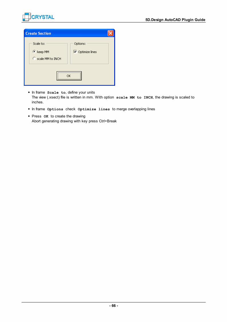
- 66 -
5D.Design AutoCAD Plugin Guide
In frame Scale to, define your units
The view (.xsect) file is written in mm. With option scale MM to INCH, the drawing is scaled to
inches.
In frame Options check Optimize lines to merge overlapping lines
Press OK to create the drawing
Abort generating drawing with key press Ctrl+Break
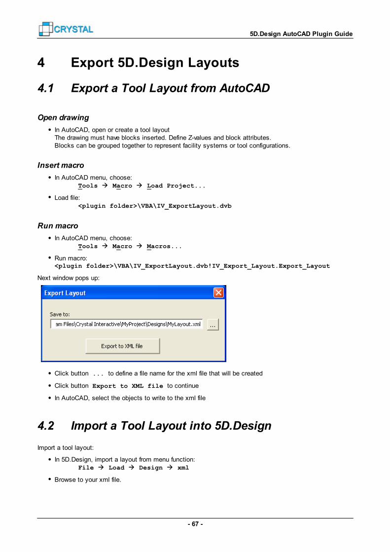
- 67 -
5D.Design AutoCAD Plugin Guide
4 Export 5D.Design Layouts
4.1 Export a Tool Layout from AutoCAD
Open drawing
In AutoCAD, open or create a tool layoutThe drawing must have blocks inserted. Define Z-values and block attributes.Blocks can be grouped together to represent facility systems or tool configurations.
Insert macro
In AutoCAD menu, choose: Tools Macro Load Project...
Load file: <plugin folder>\VBA\IV_ExportLayout.dvb
Run macro
In AutoCAD menu, choose: Tools Macro Macros...
Run macro:<plugin folder>\VBA\IV_ExportLayout.dvb!IV_Export_Layout.Export_Layout
Next window pops up:
Click button ... to define a file name for the xml file that will be created
Click button Export to XML file to continue
In AutoCAD, select the objects to write to the xml file
4.2 Import a Tool Layout into 5D.Design
Import a tool layout:
In 5D.Design, import a layout from menu function: File Load Design xml
Browse to your xml file.
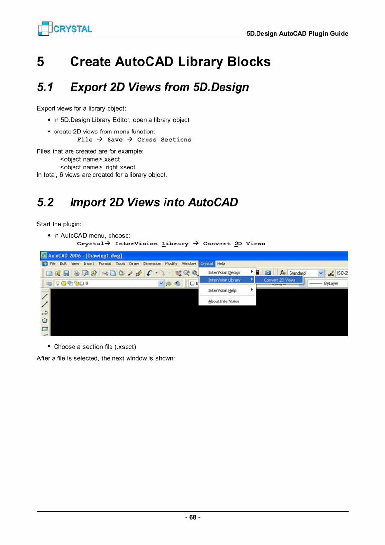
- 68 -
5D.Design AutoCAD Plugin Guide
5 Create AutoCAD Library Blocks
5.1 Export 2D Views from 5D.Design
Export views for a library object:
In 5D.Design Library Editor, open a library object
create 2D views from menu function: File Save Cross Sections
Files that are created are for example: <object name>.xsect <object name>_right.xsectIn total, 6 views are created for a library object.
5.2 Import 2D Views into AutoCAD
Start the plugin:
In AutoCAD menu, choose: Crystal InterVision Library Convert 2D Views
Choose a section file (.xsect)
After a file is selected, the next window is shown:

- 69 -
5D.Design AutoCAD Plugin Guide
In frame Create 2D Views for, choose
Only this file to convert one file, or
All files in folder to convert all files in its directory
In frame Scale to, define your units
The view (.xsect) file is written in mm. With option scale MM to INCH, the drawing is scaled to
inches.
In frame Folders, check options to:
o Save the blocks in sub folders
Check Save 2D views in subfolders to create subfolders, in which the files will be
saved. For example, process tool files will be saved in folders: .\Process Tool .\Process Tool\outlines .\Process Tool\sides
o Move xsect files when converted
Optionally check Move done .xsect files to ‘.\xsect’ to create a subfolder, to
which the converted .xsect files will be moved.
Press OK to create the drawings
Abort generating drawings with key press Ctrl+Break

- 70 -
5D.Design AutoCAD Plugin Guide
6 APPENDIX
6.1 Drawings
6.1.1 Overall Drawings
Drawings dwg Code
General – Drawing List G001
General – Grid G100 **
General – Grid Sections G201, G202 **
Building – Data Sheet B050
Building – Floor Plans B1## **
Building – Sections B2@@ **
Architectural – Data Sheet A050
Architectural – Floor Plans A1## **
Architectural – Sections A2@@ **
Architectural – Layout 3D A400
Facility Configuration – Data Sheet F050
Facility Configuration – Tool Layouts F1## **
Facility Configuration – Sections F2@@ **
Facility Configuration – Layout 3D F400
Tool Configuration – Data Sheet T050
Tool Configuration – Tool Layouts T1## **
Tool Configuration – Sections T2@@ **
Tool Configuration – Layout 3D T400
Distribution – Data Sheet – per utility group – per utility *
D050D05$D05$-$$
Distribution – Routing Plans – per utility group * – per utility *
D1##D1##-$$D1##-$$-$$
**
Distribution – Sections – per utility group * – per utility *
D2@@D2@@-$$D2@@-$$-$$
**
Custom – Sections: Floor Plans Sections
C1##C2@@
****
Custom – Pictures C300
* Not used when creating all overall plans ** Also used as xref drawing
## = floor level nr@@ = grid line$$ = utility group nr$$-$$ = utility group – utility nr
Next drawings contain next objects:General System grid and floor levelsBuilding Columns, popouts, floor cutouts, gridsArchitectural All inserted objects/tools that not belong to a facility or tool configuration, such as floor tiles,
pedestals, pipe rack,s etcFacility Configuration All inserted objects/tools that belong to a facility configuration
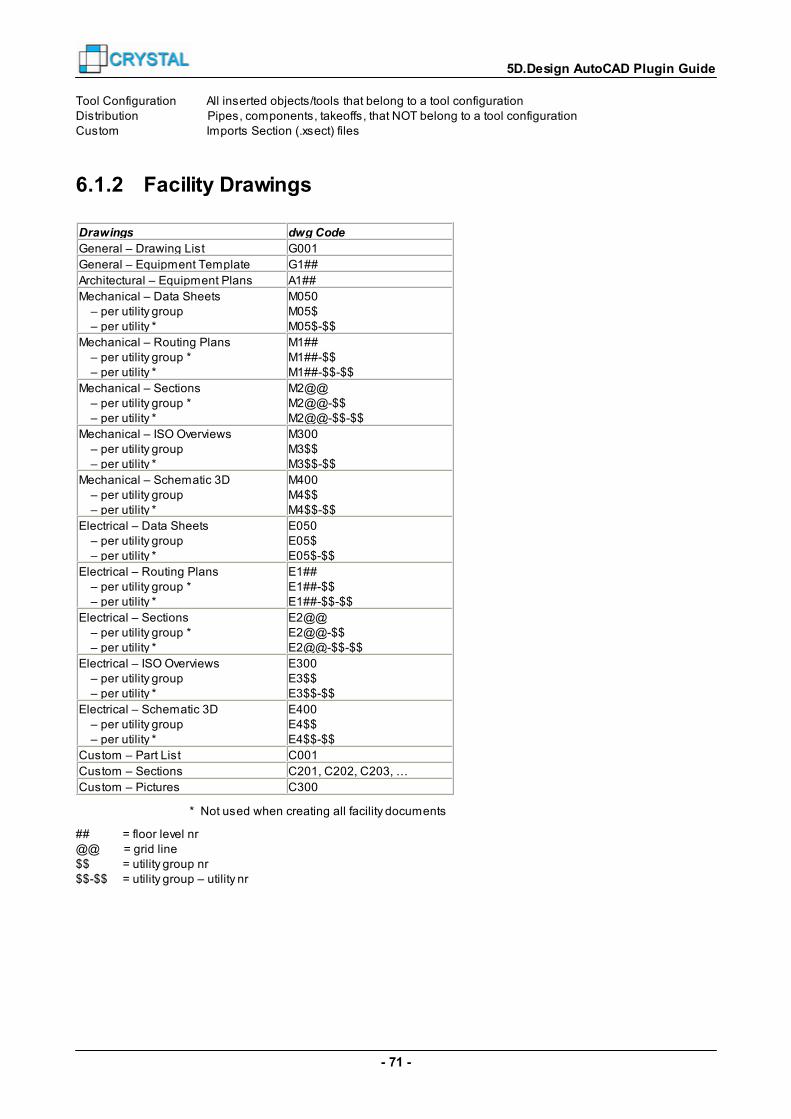
- 71 -
5D.Design AutoCAD Plugin Guide
Tool Configuration All inserted objects/tools that belong to a tool configurationDistribution Pipes, components, takeoffs, that NOT belong to a tool configurationCustom Imports Section (.xsect) files
6.1.2 Facility Drawings
Drawings dwg Code
General – Drawing List G001
General – Equipment Template G1##
Architectural – Equipment Plans A1##
Mechanical – Data Sheets – per utility group – per utility *
M050M05$M05$-$$
Mechanical – Routing Plans – per utility group * – per utility *
M1##M1##-$$M1##-$$-$$
Mechanical – Sections – per utility group * – per utility *
M2@@M2@@-$$M2@@-$$-$$
Mechanical – ISO Overviews – per utility group – per utility *
M300M3$$M3$$-$$
Mechanical – Schematic 3D – per utility group – per utility *
M400M4$$M4$$-$$
Electrical – Data Sheets – per utility group – per utility *
E050E05$E05$-$$
Electrical – Routing Plans – per utility group * – per utility *
E1##E1##-$$E1##-$$-$$
Electrical – Sections – per utility group * – per utility *
E2@@E2@@-$$E2@@-$$-$$
Electrical – ISO Overviews – per utility group – per utility *
E300E3$$E3$$-$$
Electrical – Schematic 3D – per utility group – per utility *
E400E4$$E4$$-$$
Custom – Part List C001
Custom – Sections C201, C202, C203, …
Custom – Pictures C300
* Not used when creating all facility documents
## = floor level nr@@ = grid line$$ = utility group nr$$-$$ = utility group – utility nr

- 72 -
5D.Design AutoCAD Plugin Guide
6.1.3 Hookup Drawings
Drawings dwg Code
General – Drawing List G001
General – Equipment Templates G1##
Architectural – Equipment Plans A1##
Architectural – Elevations A200
Mechanical – Schematic Drawing – per utility group – per utility *
M000M0$$M0$$-$$
Mechanical – Data Sheet – per utility group – per utility *
M050M05$M05$-$$
Mechanical – Routing Plans – per utility group * – per utility *
M1##M1##-$$M1##-$$-$$
Mechanical – Sections – per utility group * – per utility *
M201, M202, M203, M204M201-$$ / M202-$$ / …M201-$$-$$ / …
Mechanical – ISO Overviews – per utility group – per utility *Mechanical – ISO Drawings
M300M3$$M3$$-$$M3$$_&&&
Mechanical – Routing 3D – per utility group – per utility *
M400M4$$M4$$-$$
Electrical – Schematic Drawing – per utility group – per utility *
E000E0$$E0$$-$$
Electrical – Data Sheet – per utility group – per utility *
E050E05$E05$-$$
Electrical – Routing Plans – per utility group * – per utility *
E1##E1##-$$E1##-$$-$$
Electrical – Sections – per utility group * – per utility *
E201, E202, E203, E204E201-$$ / E202-$$ / …E201-$$-$$ / …
Electrical – Overviews – per utility group – per utility *
E300E3$$E3$$-$$
Electrical – Routing 3D – per utility group – per utility *
E400E4$$E4$$-$$
Structural – Plans S1##
Structural – Elevations S201, S202
Custom – Part List C001
Custom – Sections C201, C202, C203, …
Custom – Pictures C300
* Not used when creating all hookup documents
## = floor level nr$$ = utility group nr$$-$$ = utility group – utility nr&&& = POC nr

- 73 -
5D.Design AutoCAD Plugin Guide
6.2 Variables
Path Variables
Variable Description and example
<IV> Crystal 5D folderC:\Crystal 5D\
. XML file locationC:\Crystal 5D\MyProject\Designs\
<LIB> Project AutoCAD Library folderC:\Crystal 5D\MyProject.Acad.Library\
<SLIB> Standard AutoCAD Library folderC:\Crystal 5D\MyStandard.Acad.Library\
Drawing Selection Variables
Variable Description Example
<dwgGroup> Drawing group Mechanical
<dwgG> First character of drawinggroup
M
<dwgArea> Drawing area,incl. utility (group) nameFor ISO drawings, the POCnumber is added.
Fab FloorIsometric-GASIsometric-GAS_08
<dwgA> Number of drawing area,incl. utility (group) nameFor ISO drawings, the POCnumber is added.
1303GAS3GAS_08
<dwgNr> Number of drawing area,incl. utility numberFor ISO drawings, the POCnumber is added.
130302-15302-15_08
<L> Floor level number 30
Design Variables
Variable Description Example
<PRO> Project name MyProject
<A> Building areaIf no building area is defined, the closestgrid name is used for Hookup drawings.
Bay 14F/14
<C> Facility or Tool Configuration name CVD420_1
<C’> Part of Facility or Tool Configurationname: minus underscore and digits
CVD420
<C’’> Part of Facility or Tool Configurationname: all character not A-Z are removedfrom the right.
CVD
Tool Variables
Variable Description Example
<C> Facility or Tool Configuration name CVD420

- 74 -
5D.Design AutoCAD Plugin Guide
<T> Tool or Object type rack
POC and Pipe / Duct Variables
Variable Description Example
<P> POC ID 08
<U> Utility name for a POC, pipe or duct HPHe
<U’> Utility group name for a POC, pipe orduct
GAS
<M> Material name for a pipe or duct PVC
<D> Dimension for a pipe or duct.If no dimension is defined, the diameteror rectangular size is used. For adiameter, a sign can be added in front (“
” or “d”).
DN 25
<d> Diameter or rectangular size for a pipe orduct.For a diameter, a sign can be added infront (“ ” or “d”).
800x250
50
<z> Z-value of center of pipe or duct 12350
<z+> Z-value of top of pipe or duct 12375
<z-> Z-value of bottom of pipe or duct 12325
<Z> Z-value of center of pipe or duct fromfloor level
4350
<Z+> Z-value of top of pipe or duct from floorlevel
4375
<Z-> Z-value of bottom of pipe or duct fromfloor level
4325
Other Data
Variable Description Example
<p:*> Object property value, defined in designfile (.xml)For example: <p:tooldisplayname>
TAS 301
<d:*> POC data value, defined in design file (.xml)For example: <d:Object Code>
SC1015
6.3 Symbols
6.3.1 General Symbols
Description Block
General note G-GENNOTE
Key note G-KEYNOTE
System grid label
G-GRID

- 75 -
5D.Design AutoCAD Plugin Guide
System grid point
G-GRIDPOINT
G-GRIDPOINT_ISO
Floor level heightG-LEVEL
Cross section icons G-CROSS1
G-CROSS2
To sheet
G-SHEET
North arrow
G-NORTH
Scale IconG-SCALE
Keyplan mark G-KEYPLANMARK
XYZ location
G-POINT
Tool datum point
G-DATUM
Equipment boundary
G-EB
Takeoff point G-NEWCONN
Pipe slope G-SLOPE
6.3.2 Component Symbols
Description Block
ReducerREDUCER
Elbow ELBOW
Tee Piece TEE
Connection to pipe DUMMYTEE
Pipe-hose adapterADAPTER
End cap
ENDCAP
Ground point
GROUNDPOINT
Takeoff TAKEOFF
Isometric P.O.C. ISO_POC

- 76 -
5D.Design AutoCAD Plugin Guide
Isometric takeoff (end-P.O.C.) ISO_TO
Isometric takeoff
ISO_TAKEOFF
Fitting FITTING
Weld point WELD
6.3.3 Symbol Labels
Description Block
Mechanical POC
FM_POCM
Electrical POC
FM_POCE
Connection to takeoff(end-P.O.C.) FM_LPOC
Connector FM_CON
Continue pipe on nextsheet FM_CONTINUE
Popout
FM_POPOUT
Component
ISO_Valve
Pipe
ISO_Pipe
Fitting
ISO_Fitting
Weld point
ISO_Weld
6.3.4 Attribute Blocks
Attributes for routing plans
Description Block
Tool attributes
ATT_TOOL
CONFIGURATION
NAMEComponent attr.
ATT_COMPONENT
NO
DNAME
Typical attributes ATT_TYP NAME
POC attributes ATT_POC UTILITY
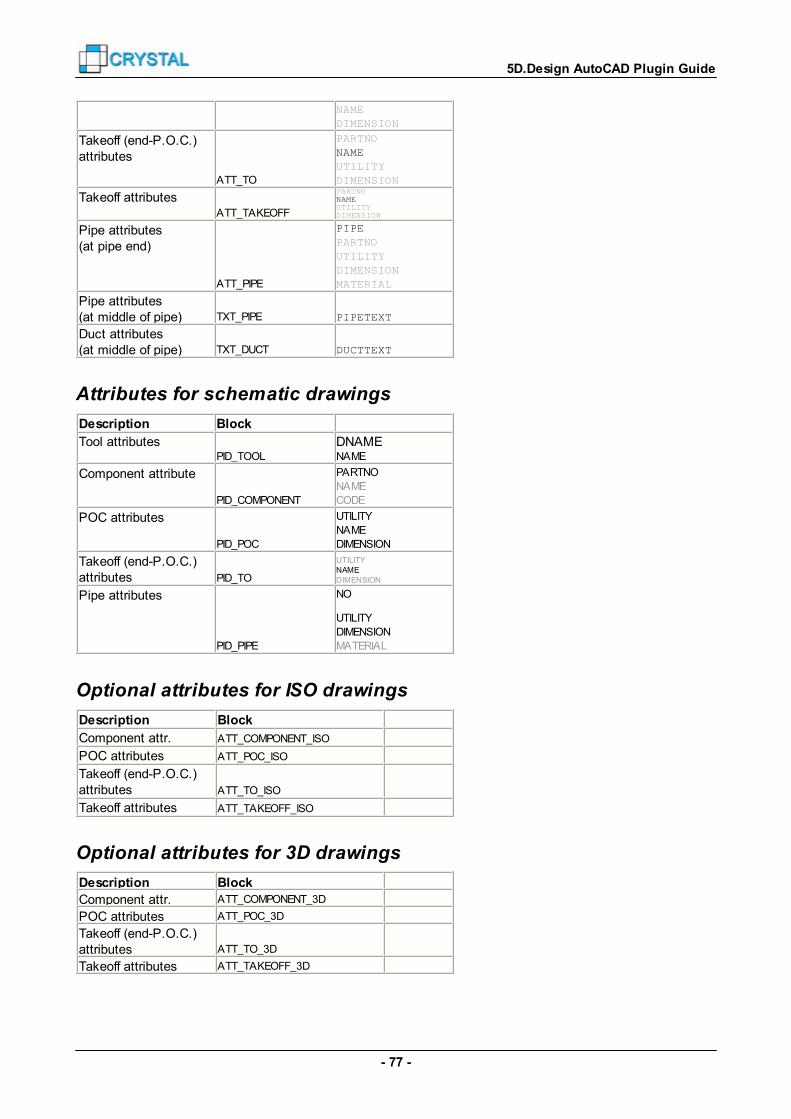
- 77 -
5D.Design AutoCAD Plugin Guide
NAME
DIMENSION
Takeoff (end-P.O.C.)attributes
ATT_TO
PARTNO
NAME
UTILITY
DIMENSION
Takeoff attributesATT_TAKEOFF
PARTNONAMEUTILITYDIMENSION
Pipe attributes(at pipe end)
ATT_PIPE
PIPE
PARTNO
UTILITY
DIMENSION
MATERIAL
Pipe attributes(at middle of pipe) TXT_PIPE PIPETEXT
Duct attributes(at middle of pipe) TXT_DUCT DUCTTEXT
Attributes for schematic drawings
Description Block
Tool attributesPID_TOOL
DNAMENAME
Component attribute
PID_COMPONENT
PARTNO
NAME
CODE
POC attributes
PID_POC
UTILITY
NAME
DIMENSION
Takeoff (end-P.O.C.) attributes PID_TO
UTILITYNAMEDIMENSION
Pipe attributes
PID_PIPE
NO
UTILITY
DIMENSION
MATERIAL
Optional attributes for ISO drawings
Description Block
Component attr. ATT_COMPONENT_ISO
POC attributes ATT_POC_ISO
Takeoff (end-P.O.C.)attributes ATT_TO_ISO
Takeoff attributes ATT_TAKEOFF_ISO
Optional attributes for 3D drawings
Description Block
Component attr. ATT_COMPONENT_3D
POC attributes ATT_POC_3D
Takeoff (end-P.O.C.)attributes ATT_TO_3D
Takeoff attributes ATT_TAKEOFF_3D

- 78 -
5D.Design AutoCAD Plugin Guide
6.3.5 Piping Symbols
Round Rectangular Single line
EndF_END D_END C_END
DropF_DROP D_DROP C_DROP
Vertical
F_VERT D_VERT C_VERT
U_VERT
RiseF_RISE D_RISE C_RISE
U_RISE
Blocks *_END are used when a chain starts or ends horizontal.
Blocks *_DROP are used when a pipe bends down (not when it bends up). This symbol is also used when ablock is created for an elbow that bends down.
Blocks *_VERT are used when a chain starts or end vertical (or in an angle), or where a pipe goes through thefloor to a lower level.
Blocks *_RISE are used where a pipe goes through the floor above, to a higher floor level.
6.4 Object Types
3DFACE 3DSOLID ACAD_PROXY_ENTITY
ARC ATTDEF ATTRIB
BODY CIRCLE DIMENSION
ELLIPSE HATCH IMAGE
INSERT LEADER LINE
LWPOLYLINE MLINE MTEXT
OLEFRAME OLE2FRAME POINT
POLYLINE RAY REGION
SEQEND SHAPE SOLID
SPLINE TABLE TEXT
TOLERANCE TRACE VERTEX
VIEWPORT WIPEOUT XLINE
6.5 Wildcards
Characters in pattern Matches in string
? Any single character.
# Any single numeric digit (0-9).
* Zero or more characters.
[charlist] Any single character in charlist.F.e.: [AEY], [4-7], [A-CX-Z], [025]

- 79 -
5D.Design AutoCAD Plugin Guide
The characters are not case-sensitive.
6.6 Error Messages
6.6.1 Failed to open project from file
When you received a macro from Crystal 5D Technologies, and you installed the Crystal 5D AutoCAD Pluginsomewhere else than on C:\Crystal 5D\AutoCAD.Plugin, then you might receive an AutoCAD message:
This is not an error, but a notification from AutoCAD.The macro from your acad library has the file 'IV_DrawingChanges.dvb' attached. It is found in another folderthan the default install folder.Press 'OK' to close the window.
To fix this problem, do the next steps:Open the macro in Visual Basic Editor (in AutoCAD).Check if the reference to 'IV_DrawingChanges.dvb' exists.Save the macro
If you save the macro, the macro will NOT search for the file 'IV_DrawingChanges.dvb' on 'C:\Program Files\...'anymore, but where the reference to this dvb file is found, and therefore the message window will not be shownanymore.
Note that this problem can occur each time you install a new library that contains a macro file.
6.6.2 Do you want to save the changes...?
When you received a macro from Crystal 5D Technologies, you might receive an AutoCAD message:
This is not an error, but a notification from AutoCAD.The macro from your acad library was changed when running the plugin.Press 'Yes' to save the macro.
Note that this problem can occur each time you install a new library that contains a macro file.

- 80 -
5D.Design AutoCAD Plugin Guide
6.6.3 Drawing not saved!
This error occurs when the plugin cannot save the drawing.
The drawing cannot be saved because an invalid file name is defined, or because a drawing with this file nameis already open.
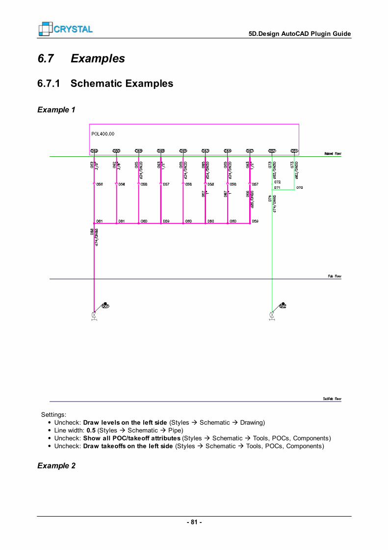
- 81 -
5D.Design AutoCAD Plugin Guide
6.7 Examples
6.7.1 Schematic Examples
Example 1
Settings:Uncheck: Draw levels on the left side (Styles Schematic Drawing)Line width: 0.5 (Styles Schematic Pipe)Uncheck: Show all POC/takeoff attributes (Styles Schematic Tools, POCs, Components)Uncheck: Draw takeoffs on the left side (Styles Schematic Tools, POCs, Components)
Example 2

- 82 -
5D.Design AutoCAD Plugin Guide
Settings:Check: Draw levels on the left side (Styles Schematic Drawing)Line width: 0.0 (Styles Schematic Pipe)Check: Show all POC/takeoff attributes (Styles Schematic Tools, POCs, Components)Check: Draw takeoffs on the left side (Styles Schematic Tools, POCs, Components)
6.7.2 Routing Examples
Example 1
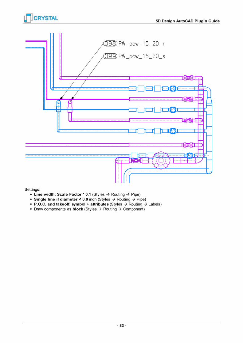
- 83 -
5D.Design AutoCAD Plugin Guide
Settings:Line width: Scale Factor * 0.1 (Styles Routing Pipe)Single line if diameter < 0.0 inch (Styles Routing Pipe)P.O.C. and takeoff: symbol + attributes (Styles Routing Labels)Draw components as block (Styles Routing Component)

- 84 -
5D.Design AutoCAD Plugin Guide
Example 2
Settings:Line width: Scale Factor * 0.05 (Styles Routing Pipe)Single line if diameter < 1000.0 inch (Styles Routing Pipe)P.O.C. and takeoff: attributes only (Styles Routing Labels)with attribute “PIPE” value “Draw component as box with symbol (Styles Routing Component)

5D.Design AutoCAD Plugin Guide
- 85 -
Index
- [ -[OBJECT] 68
- 5 -5D.Design 10, 11, 65, 67, 68
- A -All Documents 45, 47, 48, 49
Attributes 32, 33, 34, 35, 36
AutoCAD blocks 54create AutoCAD blocks 65
export 5D library objects 65
symbols 54
AutoCAD Libraries 28
AutoCAD macros block functions 60
create a macro 56
drawing functions 63
general functions 59
object functions 59
paperspace macro functions 63
pre-defined functions 58
xref functions 62
AutoCAD symbols 54attributes 76
components 75
general 74
labels 76
pipes 78
- B -Blocks 54
- C -Change Settings 24
configure plugin 6
projects 8
Convert 2D Views 68
Convert Section 65
Create All Facility Documents 17
Create All Hookup Documents 22
Create All Overall Plans 13
Create Specific Facility Document 14
Create Specific Hookup Document 19
Create Specific Overall Plan 12
- D -Dimension Styles 30
Drawing Field 31
drawing names Facility Drawings 71
Hookup Drawings 72
Overall Drawings 70
Drawing Properties 50
Drawing Scale 30
Drawing Templates 27, 51
Drawings 70, 71, 72
- E -Error message 79, 80
Example 81, 82
Export CAD 10
Export Layout 67
Export Section 10, 11, 65
- F -File Names 27
File Properties 50
- G -General Notes 53
- I -import
all facility drawings 17
all hookup drawings 22
facility drawing 14
overall drawing 12
overall drawing set 13
tool configuration drawing 19
5D.Design AutoCAD Plugin Guide
- 86 -
- K -Keyed Notes 53
- L -Layer Names 29
Layers 29
Library Editor 68
- M -Macro 26, 56
Macro Functions 58, 59, 60, 62, 63
Messages 26
- N -notes
general notes 53
keyed notes 53
- O -Object Types 78
Options 26
- P -Paper 31
PROJECTNAME 49
- R -Register 6, 8
Run installer 4, 7, 8
- S -Save 27
Save Paths 27
Save Picture 11
Scales and Texts 30
Search Paths 28
Settings 24
Styles 36, 37, 38, 39, 40, 41, 44, 45
Symbols 54, 74, 75, 76, 78
system variable PROJECTNAME 49
- T -Text Field 31
Text Styles and Heights 30
- U -User Defined Search Paths 28
- V -Variables 73
VBA 4
- W -Wildcards 78
- X -XRef 26
- Z -Zoom Drawing 31


