5G K-SimNet: End-to-End Performance Evaluation of 5G Cellular Systems Siyoung Choi † , Junghwan Song ‡ , Junseok Kim † , Suhun Lim † , Sunghyun Choi † , Ted Taekyoung Kwon ‡ , and Saewoong Bahk † † Department of Electrical and Computer Engineering and INMC, ‡ Department of Computer Science and Engineering, Seoul National University, Seoul, South Korea Email: [email protected], [email protected], {jskim14, shlim}@mwnl.snu.ac.kr, {schoi, tkkwon, sbahk}@snu.ac.kr Abstract—We introduce 5G K-SimNet, a network simulator for evaluating end-to-end performance of the fifth generation (5G) cellular system. 5G K-SimNet provides the features of 5G new radio (NR), 5G core, multi-radio access technology (RAT) protocol, traffic management on multi-connectivity, and software- defined network/network function virtualization (SDN/NFV). In this paper, we present the features of 5G K-SimNet, scenarios that can be simulated by using the simulator, and the simulation results. Index Terms—5G new radio, 5G core network, multi- connectivity, SDN, NFV, network simulator. I. I NTRODUCTION Evolution to the fifth generation (5G) in cellular system is essential due to explosive mobile traffic and demand for high data rate service. Until 2018, 3GPP group have performed standardization of the 5G mobile communication system. As part of the first phase of 5G standardization, the deployment methodology of 5G new radio (NR) and the necessity for network softwarization are discussed [1]. [2] provides an overview of the multi-connectivity operation by using long term evolution (LTE) and NR access technologies as non- standalone deployment of 5G NR, where 5G NR is deployed as secondary cell of LTE network. Software-defined net- work/network function virtualization (SDN/NFV) is discussed as a promising solution for network softwarization [3]. 5G NR standalone, which is discussed in the second phase, provides whole end-to-end 5G network architecture and protocols. It means that the fourth generation (4G) core, i.e., evolved packet core (EPC), should be completely replaced with 5G core, which includes access and mobility management func- tion (AMF), session management function (SMF), and user plane function (UPF) with network softwarization [4]. An open-source millimeter-wave (mmWave) simulation tool is introduced by New York University (NYU) WIRELESS and the University of Padova for evaluating LTE-like 5G mmWave cellular networks [5], which is developed as a new module within the network simulator-3 (ns-3) [6]. ns-3 is an open- source platform that provides various protocols including Wi- Fi, LTE, etc., in C++. ns-3 mmWave simulation tool has the features of the 3GPP channel model, the dual connec- tivity functionality, the orthogonal frequency division mul- tiplexing (OFDM)-based physical (PHY) layer, medium ac- cess control (MAC)-layer with their proposed flexible/variable transmission time interval (TTI) time division multiple ac- cess (TDMA) scheme, and the radio link control (RLC) layer. The end-to-end mmWave simulation runs with EPC, which is not 5G core. An open-source SDN simulation module focused on Open- Flow protocol is included in ns-3 itself, but the version of module is outdated. It supports OpenFlow version 0.9.x. Most of recent commercial SDN switches now support OpenFlow version 1.3. Therefore, we attempt to import external module, named ofswitch13, which is developed by the University of Campinas. It includes SDN switches and a controller which have features of OpenFlow version 1.3. Representative fea- tures about flow tables, matching or table miss of OpenFlow version 1.3 are included except auxiliary connections or en- cryption functions. In this paper, we introduce 5G K-SimNet, a network simula- tor for evaluating end-to-end performance of 5G system (5GS). It is developed as new modules of ns-3 with the features of 5G NR, 5G core, multi-radio access technology (RAT) protocol, traffic management on multi-connectivity, and SDN/NFV by using the existing simulators such as LENA and mmWave ns-3. Specifically, we update the channel model in ns-3 [7] to support the cross polarization antenna model [8]. We also add the analog beamforming model defined in the full dimension-multiple input multiple output (FD-MIMO) [9]. We implement multi-RAT protocol and split bearer for providing multi-path transmission on multi-connectivity architecture. We design a new handover procedure for secondary node (SN) change, which is not standardized in 3GPP specification but is necessary for low latency communication. We connect SDN switches with the next generation node B (gNB) and core network nodes, while enabling SDN application with an SDN controller. On the other hand, we also add virtualization mod- ules which include workload generation based on user inputs and delay estimations of scaling in-and-out, and migration. We summarize key features of 5G K-SimNet and the existing simulators in Table I. II. 5G K-SIMNET:MAIN FEATURES Fig. 1 represents the simulator architecture of 5G K-SimNet, which is expanded from ns-3 and its SDN module [12].
Transcript
5G K-SimNet: End-to-End Performance Evaluationof 5G Cellular Systems
†Department of Electrical and Computer Engineering and INMC, ‡Department of Computer Science and Engineering,Seoul National University, Seoul, South Korea
Abstract—We introduce 5G K-SimNet, a network simulatorfor evaluating end-to-end performance of the fifth generation(5G) cellular system. 5G K-SimNet provides the features of 5Gnew radio (NR), 5G core, multi-radio access technology (RAT)protocol, traffic management on multi-connectivity, and software-defined network/network function virtualization (SDN/NFV). Inthis paper, we present the features of 5G K-SimNet, scenariosthat can be simulated by using the simulator, and the simulationresults.
Index Terms—5G new radio, 5G core network, multi-connectivity, SDN, NFV, network simulator.
I. INTRODUCTION
Evolution to the fifth generation (5G) in cellular system isessential due to explosive mobile traffic and demand for highdata rate service. Until 2018, 3GPP group have performedstandardization of the 5G mobile communication system. Aspart of the first phase of 5G standardization, the deploymentmethodology of 5G new radio (NR) and the necessity fornetwork softwarization are discussed [1]. [2] provides anoverview of the multi-connectivity operation by using longterm evolution (LTE) and NR access technologies as non-standalone deployment of 5G NR, where 5G NR is deployedas secondary cell of LTE network. Software-defined net-work/network function virtualization (SDN/NFV) is discussedas a promising solution for network softwarization [3]. 5G NRstandalone, which is discussed in the second phase, provideswhole end-to-end 5G network architecture and protocols. Itmeans that the fourth generation (4G) core, i.e., evolvedpacket core (EPC), should be completely replaced with 5Gcore, which includes access and mobility management func-tion (AMF), session management function (SMF), and userplane function (UPF) with network softwarization [4].
An open-source millimeter-wave (mmWave) simulation toolis introduced by New York University (NYU) WIRELESS andthe University of Padova for evaluating LTE-like 5G mmWavecellular networks [5], which is developed as a new modulewithin the network simulator-3 (ns-3) [6]. ns-3 is an open-source platform that provides various protocols including Wi-Fi, LTE, etc., in C++. ns-3 mmWave simulation tool hasthe features of the 3GPP channel model, the dual connec-tivity functionality, the orthogonal frequency division mul-tiplexing (OFDM)-based physical (PHY) layer, medium ac-
cess control (MAC)-layer with their proposed flexible/variabletransmission time interval (TTI) time division multiple ac-cess (TDMA) scheme, and the radio link control (RLC) layer.The end-to-end mmWave simulation runs with EPC, which isnot 5G core.
An open-source SDN simulation module focused on Open-Flow protocol is included in ns-3 itself, but the version ofmodule is outdated. It supports OpenFlow version 0.9.x. Mostof recent commercial SDN switches now support OpenFlowversion 1.3. Therefore, we attempt to import external module,named ofswitch13, which is developed by the University ofCampinas. It includes SDN switches and a controller whichhave features of OpenFlow version 1.3. Representative fea-tures about flow tables, matching or table miss of OpenFlowversion 1.3 are included except auxiliary connections or en-cryption functions.
In this paper, we introduce 5G K-SimNet, a network simula-tor for evaluating end-to-end performance of 5G system (5GS).It is developed as new modules of ns-3 with the features of 5GNR, 5G core, multi-radio access technology (RAT) protocol,traffic management on multi-connectivity, and SDN/NFV byusing the existing simulators such as LENA and mmWavens-3. Specifically, we update the channel model in ns-3 [7]to support the cross polarization antenna model [8]. Wealso add the analog beamforming model defined in the fulldimension-multiple input multiple output (FD-MIMO) [9]. Weimplement multi-RAT protocol and split bearer for providingmulti-path transmission on multi-connectivity architecture. Wedesign a new handover procedure for secondary node (SN)change, which is not standardized in 3GPP specification but isnecessary for low latency communication. We connect SDNswitches with the next generation node B (gNB) and corenetwork nodes, while enabling SDN application with an SDNcontroller. On the other hand, we also add virtualization mod-ules which include workload generation based on user inputsand delay estimations of scaling in-and-out, and migration.We summarize key features of 5G K-SimNet and the existingsimulators in Table I.
II. 5G K-SIMNET: MAIN FEATURES
Fig. 1 represents the simulator architecture of 5G K-SimNet,which is expanded from ns-3 and its SDN module [12].
TABLE I: Key features of 5G K-SimNet and existing simulators
LENA [10] mmWave ns-3 [5] 5G K-SimNet
Developer Centre Tecnologic deTelecomunicacions de Catalunya (CTTC)
NYU WIRELESS,University of Padova
Seoul National University
Description LTE/EPC simulation tool mmWave cellular simulation tool 5G end-to-end network simulation toolCore network model Simple EPC model with one gateway and MME SDN/NFV, 5G core (AMF, SMF, UPF)
RRC model- System information (MIB, SIBs)- RRC connection Establishment- RRC connection reconfiguration
- Includes LENA RRC model- Secondary node addition for
LTE-mmWave dual connectivity
- Includes mmWave ns-3 RRC model- Split bearer for LTE-mmWave
- PDCP headers defined by 3GPP- Transfer data for both U and C-plane- Maintain PDCP sequence numbers- Transfer sequence number status to
neighbor eNB for handover
- Includes LENA PDCP model- Steer traffic from LTE PDCP
to mmWave RLC
- Includes mmWave ns-3 PDCP model- Reordering for in-sequence delivery- Duplicate elimination- Timer based discard- Traffic management on split bearer· Traffic steering· Traffic splitting· Traffic duplication
RLC model
- Three RLC models defined by 3GPP· Transparent mode· Unacknowledge mode· Acknowledge mode
- Simplified model: full-buffer model
- Includes LENA RLC model- Expand RLC sequence space
to handle huge amount ofretransmission
- Includes mmWave ns-3 RLC model- RLC buffer status measurement- RLC buffer status reporting to traffic
management function
PHY/MAC model - Frequency division duplex- Time division duplex- Flexible frame structure
- Same as mmWave ns-3
Channel model - Various models [6]- Adds channel model defined in
3GPP TR 38.900 [11]- Updates channel model defined in
3GPP TR 38.901 [8]
Antenna model- Isotropic model- Cosine model- Parabolic model
- Uniform planar array(linear-polarized antenna)
- Analog beamforming [7]
- Uniform planar array(linear and cross polarized antenna)
- Analog beamforming [9](one-dimension full-connection model)
Fig. 1. Simulator architecture of 5G K-SimNet.
It has the features of 5G NR, 5G core, multi-connectivity,SDN (OpenFlow version 1.3), and NFV modules for eval-uating end-to-end performance. This section describes thekey elements of 5G developed in 5G K-SimNet. A briefintroduction goes as follows. (i) 5G NR differentiated fromthe existing 4G radio; (ii) Multi-connectivity for 5G NR;(iii) SDN/NFV technology for network virtualization and 5G
core network differentiated from the existing 4G core.
A. 5G New Radio
We implement two key elements of 5G NR based onmmWave ns-3 [5]: (i) a channel model from 0.5 to 100 GHzand (ii) beam-based MIMO operation.
3GPP provides the channel model from 0.5 to 100 GHzfor performance evaluation of 5G NR [8]. The authors in [7]implemented the channel model based on the previous techni-cal report, i.e., TR 38.900 [11]. The limitation of their studyis that they have overlooked the channel model for crosspolarized antenna array. Therefore, we update the parametersof the channel model based on the recent technical report [8],and also reflect cross polarized phase response given in [8,Eq. (7.5-28–29)].
Massive MIMO that uses multiple antennas has emerged asLTE MIMO evolves, and FD-MIMO that generates a beamincluding not only horizontal but also vertical direction isdefined in the 3GPP standard [9]. We implement the pa-rameters of two-dimension antenna array model such as thenumber and the radiation pattern of vertical (or horizontal)antenna elements. We also implement one of transceiverunit (TXRU) virtualization models, i.e., one-dimension full-
0 20 40 60 80 100 120 140 160 180Tilt angle (deg)
-180
-120
-60
0
60
120
180
Azi
mut
h an
gle
(deg
)
-80
-70
-60
-50
-40
-30
-20
-10
0
10
Fig. 2. Analog beam gain (dB) in tilt and azimuth angle space whenθtilt,m′ = 120 deg.
connection model, to make the direction of a beam vertical.Researchers can easily implement another TXRU virtualiza-tion models [9] to AntennaArrayModel class. The one-dimensionfull-connection model is defined as follows.
wm,m′ =1√M
exp
(−j 2π
λ(m− 1)dV cos θtilt,m′
), (1)
where wm,m′ is a weight between the m′-th TXRU and them-th antenna element. M is the number of vertical antennaelements, λ is wavelength of the carrier frequency, dV is thevertical antenna spacing, and θtilt,m′ is the beam tilt anglegenerated by the m′-th TXRU. Fig. 2 shows the analog beamshape and the beamforming gain when M = 8, dV = 0.8λ,and θtilt,m′ = 120 degrees. We can find the beams are formednot only in the 120 deg direction but also in the 40 degdirection, i.e., when tilt angle is 120 deg, beamforming gainis 14.47 dB, and when tilt angle is 43 deg, beamforming gain10.56 dB.
FD-MIMO uses hybrid beamforming that combines dig-ital precoding and analog beamforming. In this work, weimplement only the downlink analog beamforming model1
and observe the received signal-to-noise ratio (SNR) whenUE moves. For directional communication that uses analogbeamforming, the best pair of the beams for transceiveris determined periodically. Therefore, we define the updateperiod of an analog beamforming vector denoted by T , whichis determined by periodicity of channel state information-reference signal (CSI-RS) transmission [13].
B. Multi-Connectivity
The protocol model for multi-connectivity includes the LTEradio protocol for connecting control-plane (C-plane) andthe dual 5G NR protocol for reliable user-plane (U-plane)connection. These entities reside entirely within a UE andan evolved node B (eNB)/gNB. The model, which is basedon multi-connectivity [2], provides the cooperating networkarchitecture between 4G LTE and 5G NR in the transition
1We also have plan to extend this model to hybrid beamforming. It ispossible to use a multi-user-MIMO (MU-MIMO) technique in which data istransmitted to a plurality of users using the same radio resources.
Fig. 3. User-plane protocol of multi-connectivity in downlink case.
T-SNS-SNMNUE
HO trigger
SN handover request
SN handover request
SN handover request ACK
SN handover request ACK
RRC connection reconfig.
MN-aided non-contention based RA
RRC connection reconfig. completed
Fig. 4. SN handover procedure.
period from 4G to 5G. Fig. 3 shows the block diagramof multi-connectivity for U-plane in the downlink case. AneNB is deployed as a C-plane anchor node (master node,shortly MN) while gNB is deployed for boosting the userthroughput or balancing load between eNB and gNB (as a SN).The downlink traffic is split at the packet data convergenceprotocol (PDCP) entity of eNB and routed to either the RLCentity at eNB or at gNB. In order to exploit the multi-connectivity, the traffic split function is deployed at MN andis defined for all traffic individually. The PDCP TX entity, thesplitting layer, should perform the packet sequencing for thePDCP RX entity to re-order the split packets. On the otherhand, the PDCP RX entity, the aggregating layer, should per-form the packet re-ordering to guarantee in-sequence deliveryof the received packet to the upper layer. We develop themulti-RAT protocol stack, the packet sequencing, packet re-ordering, and simple traffic split algorithm by exploiting theconventional LTE model developed by LENA project [10], andthe mmWave radio model developed by NYU WIRELESS andthe University of Padova [5]. Furthermore, the procedure forSN handover is developed, which is described in Fig. 4. Usingthis model, we can evaluate the performance of the protocolfor multi-connectivity. For example, the following featurescan be evaluated: traffic split/routing algorithm, RLC queuemanagement scheme, MAC scheduling algorithm, mobilitysupporting functions and so on. These algorithms and schemescan be modified or developed by users. The simulation resultsare as follows: (i) end-to-end performance such as transmissioncontrol protocol (TCP) and user datagram protocol (UDP)throughput, round trip time (RTT), and congestion windowsize, (ii) specific protocol performance such as PDCP packetdrop rate, RLC queue size/delay, PHY signal-to-interference-
plus-noise ratio (SINR) values, and so forth.
C. 5G Core: SDN/NFV
It is expected that 5G core utilizes NFV and SDN [3].More specifically, in a 4G System, the EPC network functionsare implemented on black-box hardwares. However, in the5G System, network functions become softwarized, so theyare not implemented on black-boxes. 5G core is placed onan NFV platform, and each network function is installedand run on virtual machines (VMs), instead of black-boxes.These VMs can have connectivity with each other by utilizingSDN, and the SDN controller monitors or controls networktraffic among them. It can be also utilized on balancing trafficbetween core networks and radio access networks. Thesechanges make network operators be able to manage theirnetworks more easily and flexibly. For example, if a networkfunction running on a VM becomes overloaded due to too highcomputational workload, a network operator can run anotherVM through an NFV platform. Then it can migrate somepart of workloads from the original network function to anewly booted one. However, if we introduce the NFV/SDNtechniques, additional delays could be caused by provisioningand migrating VM. It might result additional delays on end-to-end communication [14]. Our SDN/NFV components includethe functions which measure these side effects of introducingNFV and SDN to the 5G System.
Virtualization side effects mean additional delay compo-nents, which do not exist on non-virtualized core networks.Additional delays come from a VNF topology which isdecided by network operators. For example, scaling delaycan be caused by introducing NFV technique to 5G corenetwork. With NFV, each 5G core network function could berun on a VM as VNF. If the VNF has 8 central processingunits (CPUs) but its workload exceeds it, NFV platform auto-scales the VNF. In this case, the VNF is scaled-out, so two (ormore) VNFs might be operated. This auto-scaling takes somedelays such as provisioning or migration delays, so user mightexperience longer latency due to NFV technique, temporally.
Other side effects can be evaluated with SDN. With SDN,the network operator can control network traffic flowingthrough core networks. Traffic re-routing or balancing op-eration can be example cases. The simulation results areend-to-end performances including VM delay, network delay,and so on. User can control traffic which flows throughSDN networks, and verify it by investigating SDN switchthroughput per port.
The simulator calculates such side effects by followingsimulation process of Fig. 5. For running a simulation, usersshould set their own simulation topology and parametersrelated to SDN/NFV operation. Once they (user codes) areprovided to the simulator, the simulator runs virtualizationmodules and SDN modules. Virtualization modules calculatevirtualization-related delays such as scaling delay or provi-sioning delay. First, simulation nodes are placed depending onthe topology of user codes. Dynamic workloads (Workloadschanges along the simulation time) of core NFs, i.e., mobility
Fig. 5. SDN/NFV simulation procedure.
management entity (MME) and packet data network/serving-gateway (P/S-GW), are generated by using static workloadsof parameters of user codes. VNF delays are calculated afterconfiguring scaling thresholds, analyzing the topology andVNF policies. SDN modules also place simulation nodes first.They configure OpenFlow switches and a controller. Afterthen they run OpenFlow application such as QoS bandwidthcontroller. The final simulation results come out by mergingresults of virtualization modules and SDN modules.
We are also implementing essential parts of 5G core fora downlink scenario: AMF, SMF, UPF [4]. With such NFs,control signals such as user equipment (UE) registration, de-registration or service requests are implemented based on3GPP specification [15]. Control signal procedures of 5GSystem differ from those of LTE System. In case of servicerequests, authentication procedures are followed after radioresource control (RRC) requests in LTE system. However, in5GS, RRC requests are followed after authentication proce-dures. It is a just representative case, however, procedures ofLTE and those 5GS show different points in details.
III. SIMULATION RESULTS
In this section, we illustrate various simulation scenariosthat can be simulated by using 5G K-SimNet and present thecorresponding results and analysis.
A. 5G New Radio
Fig. 6(a) shows simulation scenarios where gNB, UE, andbuilding are located in x-y plane. The z-axis is omitted forsimplicity. A gNB is fixed on the y-axis, and its height is21.5 m and a UE moves at a speed of 60 km/h in a directionparallel to the y-axis. We also consider scenarios withoutbuilding. The gNB operates at 28 GHz band, and its totalnumber of antenna elements and the number of TXRUs are64 and 32, respectively. Downlink packets for the UE arecontinuously generated during the simulation time, which isset to 6 s. The number of antenna elements and TXRUs for theUE are 32 and 8, respectively. We set the T value to 160 msbecause the number of CSI-RSs should be set to the samenumber of TXRUs in gNB and a minimum cycle of CSI-RSis 5 ms [13].
Fig. 6(b) shows the SNR values of received transportblocks (TBs) when the building does not exist. In an idealcase, where we know the channel matrix during the simulation,the highest SNR values can be obtained by the best analogbemaforming vectors. We set the analog beamforming vector
(a) Simulation scenario
0 1 2 3 4 5 6Time (s)
-10
0
10
20
30
40
50
SNR
(dB
)
Period (T=160 ms) Ideal
(b) Without building
0 1 2 3 4 5 6Time (s)
-10
0
10
20
30
40
50
SNR
(dB
)
Period (T=160 ms)
Ideal
(c) With building
Fig. 6. 5G NR simulation scenario and SNR values of received TBs.
(a) Simulation scenario
0 5 10 15 20 25 30
Time (s)
0
100
200
300
400
500
600
700
Thro
ughp
ut (M
bps)
Path throughput (SN1) Path throughput (SN2) Total throughput (UDP)
(b) Throughput result
Fig. 7. Multi-connectivity simulation scenario and throughput result.
update period T=160 ms to reflect the beam tracking proce-dure. We observe that the SNR values are lower than those ofthe ideal case. This is because the gNB and the UE transmitand receive data using analog beamforming vectors based onpast channel information. Fig. 6(c) represents the SNR valuesof received TBs when the building exists. In both the idealand non-ideal cases, we observe the SNR decreases sharplywhen the channel condition is changed to the non-line-of-sight (NLOS) due to the building. When the T is applied, if thechannel condition is changed, i.e., from LOS to NLOS, viceversa, the SNR value is zero. Therefore, we do not representthe minus infinity values on a log scale in Fig. 6(c).
B. Multi-Connectivity
We set the simulation scenario for evaluating the perfor-mance of mobility supporting functions as shown in Fig. 7(a).A UE can simultaneously connect multiple base stations,
eNB or gNB, on multi-connectivity architecture. Since, LTEcommunication has larger coverage but smaller capacity thanmmWave communication, we deploy eNB and gNBs as therole of MN and SNs, respectively. Here, a UE has dualconnection to two SNs to mitigate blockage effect of mmWavecommunication by exploiting diversity. Downlink user data isgenerated at server with the rate of 500 Mbps and arrives atMN through the core network. Here, we exploit multi-pathtransmission to transfer user data, that is, MN splits user datain two parts and forwards them to SNs for downlink. Splitratio can be determined by information including link statusbetween each SN and a UE, queue status of each SN, and soon. The carrier frequencies of the two gNBs connected to aUE set to be different in order to avoid inter-cell interference.All the gNBs have the bandwidth of 1 GHz. We assume thatall the gNBs and eNB are connected each other through X2interface whose delay 1 ms. A UE moves at speed of 10 km/hin a direction parallel to the y-axis. Blockages are uniformlydistributed in area with the density of 6000 blockages/km2.The size of each blockage is randomly generated between 0and 2 meters for both x and y dimensions.
The link capacity of mmWave communication is larger thanthat of LTE, but mmWave link quality can be rapidly changeddue to its nature. In case that a UE can associate with oneSN at a time, the amount of buffered traffic at associatedSN grows quickly when the link quality gets worse eventhough its duration is very short. Hence, multi-connectivity isessential for enjoying the high capacity of mmWave links bymitigating QoS degradation by exploiting the diversity gainobtained from multi-path transmission. Fig. 7(b) shows thethroughput performance of the mobile user, where two dottedlines and blue line present path throughput of 2 connected SNsand the total received throughput measured at UDP layer ofUE, respectively. Since received packets are merged and re-ordered at PDCP RX entity as shown in Fig. 3, path throughputis measured at RLC RX entity. When there is an obstaclebetween a UE and its serving SN, the path throughput isseverely degraded because received SNR from the servingSN is very low. We observe that the total throughput hasthe comparable value of the source rate and shows stablechange over time with the help of traffic management on multi-
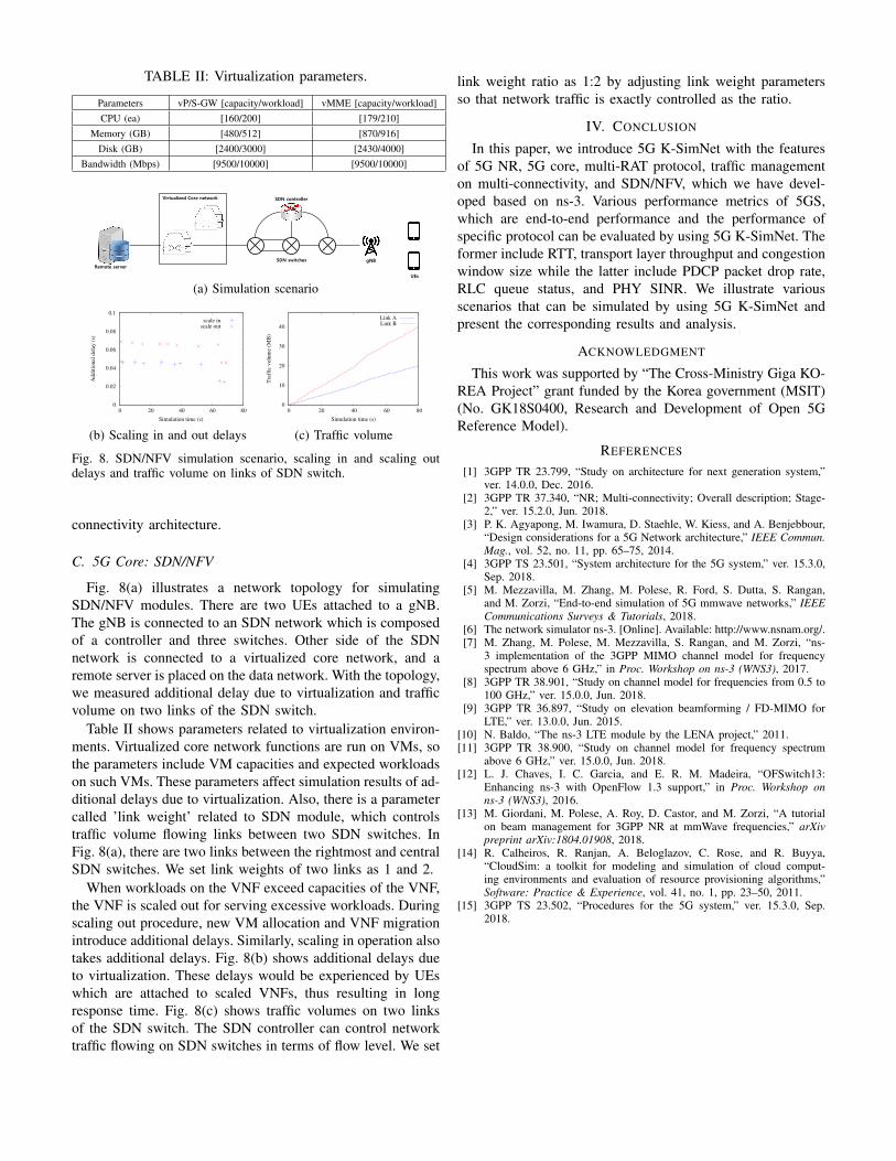
Fig. 8. SDN/NFV simulation scenario, scaling in and scaling outdelays and traffic volume on links of SDN switch.
connectivity architecture.
C. 5G Core: SDN/NFV
Fig. 8(a) illustrates a network topology for simulatingSDN/NFV modules. There are two UEs attached to a gNB.The gNB is connected to an SDN network which is composedof a controller and three switches. Other side of the SDNnetwork is connected to a virtualized core network, and aremote server is placed on the data network. With the topology,we measured additional delay due to virtualization and trafficvolume on two links of the SDN switch.
Table II shows parameters related to virtualization environ-ments. Virtualized core network functions are run on VMs, sothe parameters include VM capacities and expected workloadson such VMs. These parameters affect simulation results of ad-ditional delays due to virtualization. Also, there is a parametercalled ’link weight’ related to SDN module, which controlstraffic volume flowing links between two SDN switches. InFig. 8(a), there are two links between the rightmost and centralSDN switches. We set link weights of two links as 1 and 2.
When workloads on the VNF exceed capacities of the VNF,the VNF is scaled out for serving excessive workloads. Duringscaling out procedure, new VM allocation and VNF migrationintroduce additional delays. Similarly, scaling in operation alsotakes additional delays. Fig. 8(b) shows additional delays dueto virtualization. These delays would be experienced by UEswhich are attached to scaled VNFs, thus resulting in longresponse time. Fig. 8(c) shows traffic volumes on two linksof the SDN switch. The SDN controller can control networktraffic flowing on SDN switches in terms of flow level. We set
link weight ratio as 1:2 by adjusting link weight parametersso that network traffic is exactly controlled as the ratio.
IV. CONCLUSION
In this paper, we introduce 5G K-SimNet with the featuresof 5G NR, 5G core, multi-RAT protocol, traffic managementon multi-connectivity, and SDN/NFV, which we have devel-oped based on ns-3. Various performance metrics of 5GS,which are end-to-end performance and the performance ofspecific protocol can be evaluated by using 5G K-SimNet. Theformer include RTT, transport layer throughput and congestionwindow size while the latter include PDCP packet drop rate,RLC queue status, and PHY SINR. We illustrate variousscenarios that can be simulated by using 5G K-SimNet andpresent the corresponding results and analysis.
ACKNOWLEDGMENT
This work was supported by “The Cross-Ministry Giga KO-REA Project” grant funded by the Korea government (MSIT)(No. GK18S0400, Research and Development of Open 5GReference Model).
REFERENCES
[1] 3GPP TR 23.799, “Study on architecture for next generation system,”ver. 14.0.0, Dec. 2016.
[3] P. K. Agyapong, M. Iwamura, D. Staehle, W. Kiess, and A. Benjebbour,“Design considerations for a 5G Network architecture,” IEEE Commun.Mag., vol. 52, no. 11, pp. 65–75, 2014.
[4] 3GPP TS 23.501, “System architecture for the 5G system,” ver. 15.3.0,Sep. 2018.
[5] M. Mezzavilla, M. Zhang, M. Polese, R. Ford, S. Dutta, S. Rangan,and M. Zorzi, “End-to-end simulation of 5G mmwave networks,” IEEECommunications Surveys & Tutorials, 2018.
[6] The network simulator ns-3. [Online]. Available: http://www.nsnam.org/.[7] M. Zhang, M. Polese, M. Mezzavilla, S. Rangan, and M. Zorzi, “ns-
3 implementation of the 3GPP MIMO channel model for frequencyspectrum above 6 GHz,” in Proc. Workshop on ns-3 (WNS3), 2017.
[8] 3GPP TR 38.901, “Study on channel model for frequencies from 0.5 to100 GHz,” ver. 15.0.0, Jun. 2018.
[10] N. Baldo, “The ns-3 LTE module by the LENA project,” 2011.[11] 3GPP TR 38.900, “Study on channel model for frequency spectrum
above 6 GHz,” ver. 15.0.0, Jun. 2018.[12] L. J. Chaves, I. C. Garcia, and E. R. M. Madeira, “OFSwitch13:
Enhancing ns-3 with OpenFlow 1.3 support,” in Proc. Workshop onns-3 (WNS3), 2016.
[13] M. Giordani, M. Polese, A. Roy, D. Castor, and M. Zorzi, “A tutorialon beam management for 3GPP NR at mmWave frequencies,” arXivpreprint arXiv:1804.01908, 2018.
[14] R. Calheiros, R. Ranjan, A. Beloglazov, C. Rose, and R. Buyya,“CloudSim: a toolkit for modeling and simulation of cloud comput-ing environments and evaluation of resource provisioning algorithms,”Software: Practice & Experience, vol. 41, no. 1, pp. 23–50, 2011.
[15] 3GPP TS 23.502, “Procedures for the 5G system,” ver. 15.3.0, Sep.2018.