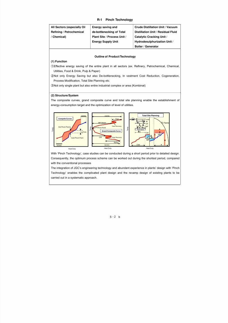
5-b1 5.REFINERY AND PETROCHEMICAL TECHNOLOGY Product No. Name of product/ technology Functional group Product group R-1 Pinch technology all sectors (especially Oil Refining / Petrochemical / Chemical) Energy saving and de-bottlenecking oftotal plant system site / process unit / energy supply unit Crude distillation unit / vacuum distillation unit / residual fluid catalytic cracking unit /hydrodesulphurization Unit /boiler / generatorR-2 WIN TRAY Extraction column Tray R-3 Hydro-carbon vapor recovery system Hydrocarbon recovery Absorber/ absorber tank forgasoline shipping facility R-4 Dense loading technology Hydrogen desulphurization, decomposerFixed bed reactor, Catalyst, High density filing, fillerR-5 Reduction in blown steam by column top steam recycle Distillation Steam recycle R-6 Power recovery of CO gas Power recovery Fluidized contact crackerR-7 Power recovery system with mixed fluid condensing turbine Power recovery Fluidized bed contact cracking R-8 Waste heat boiler for sulfur recovery Heat recovery Sulfur recovery equipment F-9 Distillation column with Intermediate reboilerDistillation in oil refining process Oil refinery plant R-10 Hydrocarbon membrane separator Membrane separation ofhydrogen Hydrogen production apparatus R-11 Heat pump type PP separ ator Propylene separ ation Heat pump method R-12 Cogeneration using gas turbine exhaust gas as combustion air forheating furnace Heat recovery cogeneration Heating furnace R-13 Rotar y Regener ative Burner System Disti llati on Tubular furnace
Transcript
8/7/2019 5_Refinery
http://slidepdf.com/reader/full/5refinery 1/24
5- b 1
5. REFINERY AND PETROCHEMICAL TECHNOLOGY
Product
No.Name of product/ technology Functional group Product group
Applicable to general liquid-liquid extraction operations.
①Extraction of aromatics from cracked gasoline.
②Extraction of organic compounds.
③Increase of capacity of existing RDC towers, perforated tray towers, or packed towers by replacing
existing trays with WIN TRAY which will bring about imposed process performance.
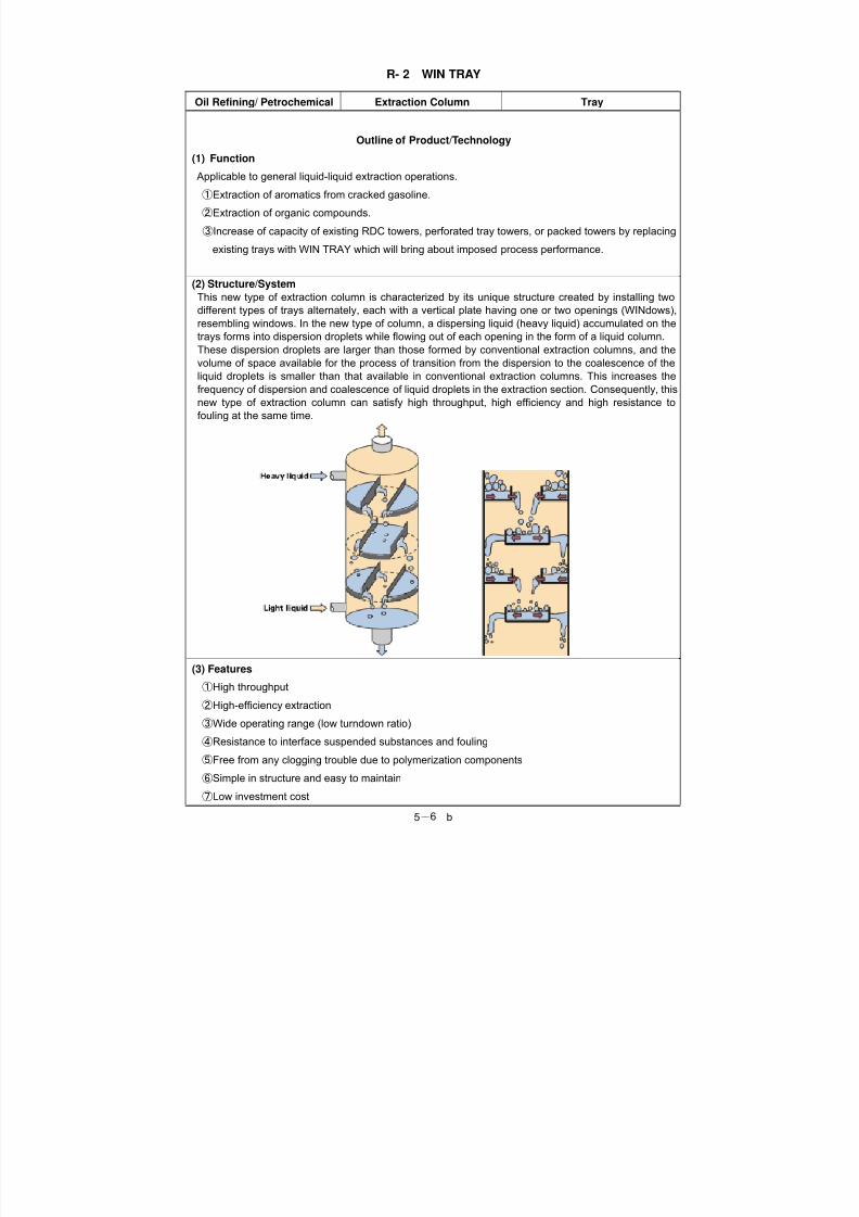
(2) Structure/System
This new type of extraction column is characterized by its unique structure created by installing twodifferent types of trays alternately, each with a vertical plate having one or two openings (WINdows),
resembling windows. In the new type of column, a dispersing liquid (heavy liquid) accumulated on the
trays forms into dispersion droplets while flowing out of each opening in the form of a liquid column.
These dispersion droplets are larger than those formed by conventional extraction columns, and the
volume of space available for the process of transition from the dispersion to the coalescence of the
liquid droplets is smaller than that available in conventional extraction columns. This increases the
frequency of dispersion and coalescence of liquid droplets in the extraction section. Consequently, this
new type of extraction column can satisfy high throughput, high efficiency and high resistance to
fouling at the same time.
(3) Features ①High throughput
②High-efficiency extraction
③Wide operating range (low turndown ratio)
④Resistance to interface suspended substances and fouling
⑤Free from any clogging trouble due to polymerization components
⑥Simple in structure and easy to maintain
⑦Low investment cost
8/7/2019 5_Refinery
http://slidepdf.com/reader/full/5refinery 7/24
8/7/2019 5_Refinery
http://slidepdf.com/reader/full/5refinery 8/24
5- b 8
R- 3 Hydro-Carbon Vapor Recovery system
Refinery/ Petrochemical Hydrocarbon recovery (1)Absorber (2)Absorbing tank
Outline of Product/Technology
(1)Function
Hydro-Carbon Vapor Recovery system recovers the hydrocarbon vapor, generating from gasolineshipping facilities at oil refineries, oil terminals etc., which may produce photochemical smog which is
one of the causes of air pollution.
(2)Structure/System
Absorption:Hydrocarbon vapor is absorbed by the solvent which is counter-currently contacting with
the feed gas.
Outlet HC concentration: 5% or less.
Adsorption:Hydrocarbon vapor is adsorbed by the adsorbent which is loaded in the adsorber.
Outlet HC concentration 1% or less.
(3)Features
① Optimal process based on the optional design for each case.
② Safety process based on the techniques for preventing electrostatic hazard.
③ Full-automatic Operation in case the client requests
Energy Saving / CO2 Emission Reduction
(1)Technical Features
Using absorption or adsorption which is a basic technology in the petroleum field and using
absorption liquid which is available in oil refineries or oil terminals to collect the hydrocarbon from the
effluent gas safely.
(2)Energy Saving/CO2 Emission Reduction
In case of gasoline shipping :
Feed gas rate : 1,500 Nm3/hr (20 car lanes)
Gasoline recovery : 1.8kl/hr during operation (for approximately 3hrs/day)
* 1,500Nm3/h×30%(conc.)× 90% (rec.)×700kg/m3
Information of Manufacture(1) Name of Company and Department: Nichiyo Engineering Corporation
(2) Address : 3-17-35,Niizo-minami, Toda, Saitama, 335-8502, Japan
Dense loading is a technology that maximizes the catalyst performance in the reactor and the general
performance of the reactor itself. Commonly used in the petroleum refining and petrochemical
industries.
(2)Structure/ System
The catalyst is loaded to reactor inside by equipments as follows.
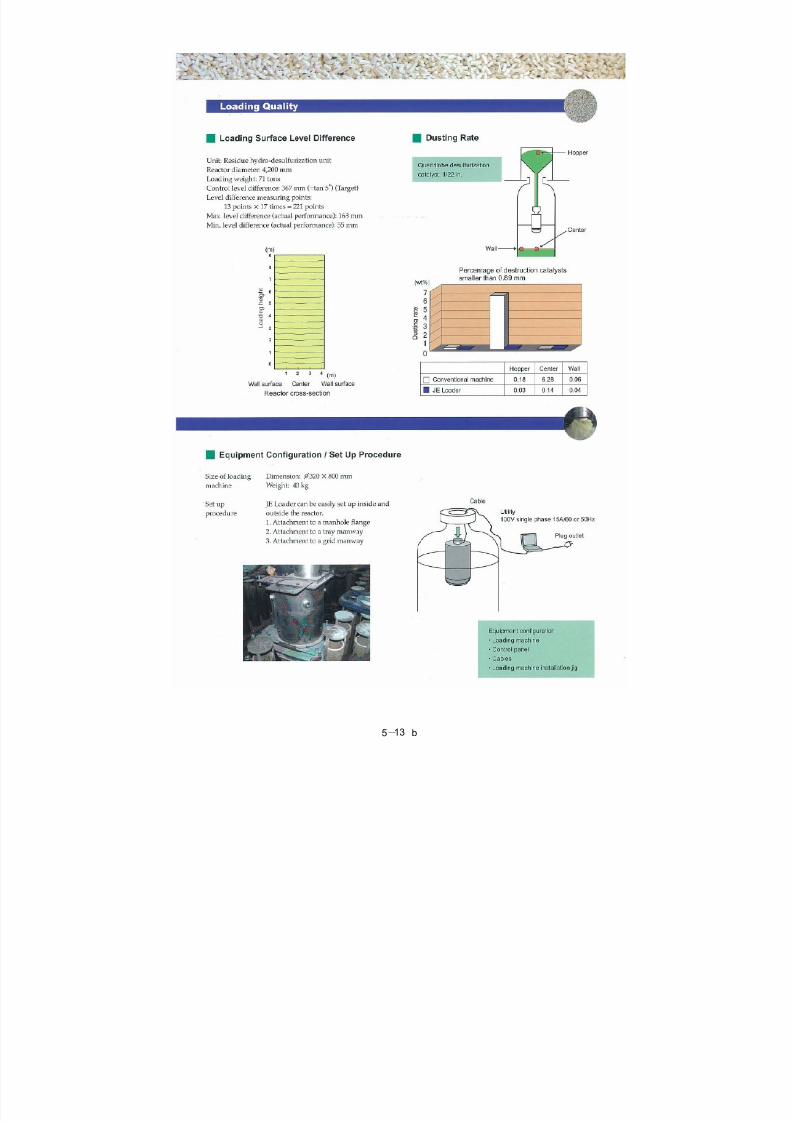
1. Loading machine
This machine is installed into the reactor or on top manhole..
This machine is controlled by control panel automatically.
2. Control system
All system is controlled by mobile computer.
(3)Features
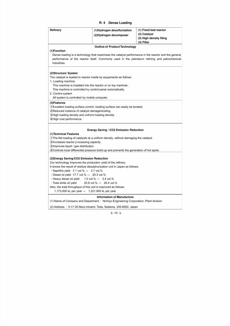
①Excellent loading surface control -loading surface can easily be leveled.
②Reduced instance of catalyst damage/dusting.
③High loading density and uniform loading density.
④High cost performance.
Energy Saving / CO2 Emission Reduction
(1)Technical Features
①The flat loading of catalysts at a uniform density, without damaging the catalyst.
②Increases reactor processing capacity.
③Improves liquid / gas distribution.
④Controls local differential pressure build-up and prevents the generation of hot spots.
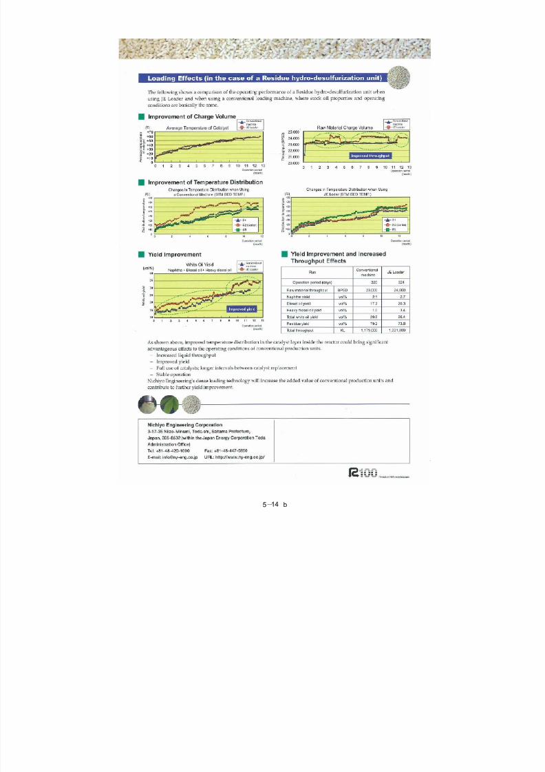
(2)Energy Saving/CO2 Emission Reduction
Our technology improves the production yield of the refinery.
It shows the result of residue desulphurization unit in Japan as follows.
・Naphtha yield 2.1 vol.%→ 2.7 vol.%
・Diesel oil yield 17.7 vol.%→ 20.3 vol.%
・Heavy diesel oil yield 1.0 vol.%→ 3.4 vol.%
・Total white oil yield 20.8 vol.%→ 26.4 vol.%
Also, the total throughput of this unit is improved as follows.
1,173,000 kL per year → 1,221,000 kL per year
Information of Manufacture
(1) Name of Company and Department : Nichiyo Engineering Corporation, Plant division
(2) Address : 3-17-35,Niizo-minami, Toda, Saitama, 335-8502, Japan
8/7/2019 5_Refinery
http://slidepdf.com/reader/full/5refinery 11/24
5- b 11
8/7/2019 5_Refinery
http://slidepdf.com/reader/full/5refinery 12/24
5- b 12
8/7/2019 5_Refinery
http://slidepdf.com/reader/full/5refinery 13/24
5- b 13
8/7/2019 5_Refinery
http://slidepdf.com/reader/full/5refinery 14/24
5- b 14
8/7/2019 5_Refinery
http://slidepdf.com/reader/full/5refinery 15/24
5- b 15
R- 5 Reduction in Blown Steam by Column Top Steam Recycle
Oil refinery Distillation Steam recycle
Outline of Product / Technology
(1) Function
At the crude oil normal pressures distillation column, steam is blown to decrease the partial pressure of
light components. The steam blown inside enters the column top condenser in the form of column top
steam, and then condensed before being drained. Using an ejector, this system implements a
technique that recycles the column top steam into blown steam.
(2) Structure / System
Flow of recycle system for decompressed distilled steam
Structure of steam ejector (thermo compressor)
(3) Features
The steam ejector lowers the internal pressure of the body by jetting high-pressure steam from the
nozzle, and absorbs the low-pressure steam to increase the pressure.
After the pressure increases, the column top steam can be recycled into blown steam, thereby
decreasing the amount of blown steam.
Energy Saving / CO2 Emission Reduction
In general, steam a little less than 30% is blown to the heating furnace coil, while steam a little larger
than 70% is blown to the column bottom. The amount of blown steam can be decreased by 15 t/h at a
rate of 100,000 barrels per day by recycling and reusing column top steam through the ejector.
The amount of steam can be decreased by 3.6 kg/B in consumption rate.
Note: Effect of decreasing the amount of steam per throughput barrel (B).
Information of Manufacturer
(1) Name of Company and Department:
(2) Address :
(3) Contact to :
Tel. : Fax.: E-mail :
Reheatingfurnace
Volumetric flow after improvementExisting line
Additional line. Equipment. Improved
Continuous
castingbloomingrolling
Body Auto control valve
Nozzle
Aspirated steam
Diffuser Aspirated drive
8/7/2019 5_Refinery
http://slidepdf.com/reader/full/5refinery 16/24
5- b 16
R- 6 Power Recovery of CO Gas
5. Oil refinery Fluidized contact cracker Power recovery
Outline of Product/Technology
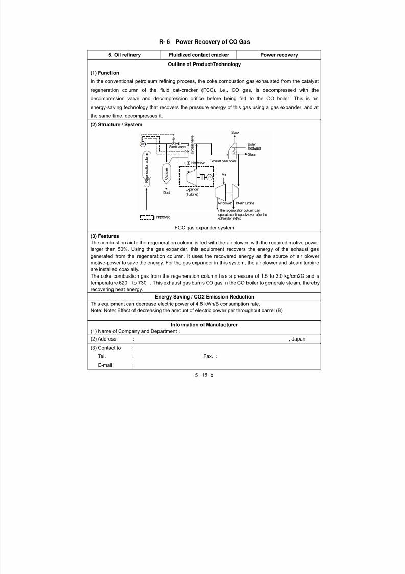
(1) Function
In the conventional petroleum refining process, the coke combustion gas exhausted from the catalyst
regeneration column of the fluid cat-cracker (FCC), i.e., CO gas, is decompressed with the
decompression valve and decompression orifice before being fed to the CO boiler. This is an
energy-saving technology that recovers the pressure energy of this gas using a gas expander, and at
the same time, decompresses it.
(2) Structure / System
FCC gas expander system
(3) Features
The combustion air to the regeneration column is fed with the air blower, with the required motive-power
larger than 50%. Using the gas expander, this equipment recovers the energy of the exhaust gas
generated from the regeneration column. It uses the recovered energy as the source of air blower
motive-power to save the energy. For the gas expander in this system, the air blower and steam turbine
are installed coaxially.
The coke combustion gas from the regeneration column has a pressure of 1.5 to 3.0 kg/cm2G and a
temperature 620 to 730 . This exhaust gas burns CO gas in the CO boiler to generate steam, therebyrecovering heat energy.
Energy Saving / CO2 Emission Reduction
This equipment can decrease electric power of 4.8 kWh/B consumption rate.
Note: Note: Effect of decreasing the amount of electric power per throughput barrel (B).
Information of Manufacturer
(1) Name of Company and Department:
(2) Address : , Japan
(3) Contact to :
Tel. : Fax.:
E-mail :
Stack valve
Stack
Boiler feedwater Steam
Exhaust heat boiler
Air
Air blower Hot-air turbine
(The regeneration column canoperate continuously even after theex ander sto s.Improved
Dust Expander
(Turbine) Regeneration column
Cyclone
Bypass valve
Inlet valve
8/7/2019 5_Refinery
http://slidepdf.com/reader/full/5refinery 17/24
5- b 17
R- 7 Power Recovery System with Mixed Fluid Condensing Turbine
Oil refinery Fluidized bed contact
cracking
Power recovery
Outline of Product/Technology
(1) Function
This is a motive-power recovery technology implemented by installing an exhaust gas expander and an
air gas condensing turbine. The expander recovers pressure/heat energy from the regeneration column
of the fluid cat-cracker (FCC), which cracks heavy oil in the petroleum refining process. The turbine
takes advantage of excessive low-pressure steam in the cracker. Note that this technology is a
motive-power recovery system (P-2) that has additionally a steam turbine. It differs from the one in P-2
in the gas turbine and steam turbine.
(2) Structure / System
(3) Features
Energy Saving / CO2 Emission Reduction
Information of Manufacturer
(1) Name of Company and Department:
(2) Address : , Japan
(3) Contact to :
Tel. : Fax.:
E-mail :
8/7/2019 5_Refinery
http://slidepdf.com/reader/full/5refinery 18/24
5- b 18
R- 8 Waste Heat Boiler for Sulfur Recovery
Oil refinery Sulfur recovery Heat recovery
Outline of Product/Technology
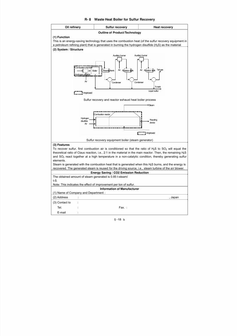
(1) Function
This is an energy-saving technology that uses the combustion heat (of the sulfur recovery equipment ina petroleum refining plant) that is generated in burning the hydrogen disulfide (H2S) as the material.
(2) System / Structure
Sulfur recovery and reactor exhaust heat boiler process
This equipment is used in the equipment that obtains more value-added propylene by fractional
distribution from propane-propylene (PP) fraction, which is a product of a fluid cat cracker (FCC). The PP
separator uses a compressor to pressurize the column top steam of the fractionating column, thereby
increasing the steam temperature, which will be taken advantage of as the heating source for the
reboiler of the fractionating column.
(Note: This technology is a type of heat pumping.)
(2) Structure / System
System diagram
(3) Features
The boiling point difference between propane and propylene is small in the heat pump system applied to
this fractionating column. Therefore, a low degree of pressurization is sufficient to enable the
motive-power to be kept low. For this reason, this fractionating column can decrease the amount of heat
of the reboiler by the entire amount relative to an ordinary fractional distillation, which heats the reboiler
with steam and uses cooling water for the condenser. It achieves fractional distillation instead with power
of approximately 20% of the decreased reboiler heating source.
Energy Saving / CO2 Emission Reduction
The effect of increase in power consumption per barrel of throughput is 1.02 kWh/B.
Information of Manufacturer
(1) Name of Company and Department:
(2) Address : , Japan
(3) Contact to :
Tel. : Fax.:
E-mail :
(Unimproved)
Propane-propylene
fraction
Cooling
water
Propylene
Steam
Propane
(Improved) Separation column
Compressor
Condenser
Reboiler Propane-propylene
fraction Accumulator
Propylene
Propylene
8/7/2019 5_Refinery
http://slidepdf.com/reader/full/5refinery 22/24
5- b 22
R-12 Cogeneration Using Gas Turbine Exhaust Gas as Combustion Air for Heating
Furnace
Oil refinery Heating furnace Cogeneration
Outline of Product/Technology
(1) FunctionThis is a power-saving technology that uses the combustion exhaust gas of the gas turbine as the
combustion air for the tubular heating furnace and further recovers the steam with the exhaust heat
boiler from the exhaust gas of the heating furnace.
(2) System / Structure
System diagram
(3) Features
After receiving the exhaust gas generated from the gas turbine generator, this equipment feeds it, as the
combustion air, to the burner of the tubular heating furnace. After heating the process fluid, the
combustion exhaust gas goes out of the heating furnace, and is led to the exhaust heat boiler, thus
causing steam to be generated. It then goes to a low temperature, and passes the induction blowing fan
before being discharged to the atmosphere. The bypass stack and the indentation air blower are
installed to enable islanding of the heating furnace and gas turbine. This equipment is used as a tubular heating furnace that decreases the fuel by approximately 25%. To achieve this, the following is used as
combustion air for that heating furnace: gas turbine power generator combustion exhaust gas that
contains oxygen with a density of 12% to 14% and that has a temperature of 480 to 550 . Further, if
this gas is used from the heating furnace exhaust gas for steam generation with the waste heat in order
to recover the secondary heat, this will be more advantage in terms of the effect of plant and equipment
investment.
Energy Saving / CO2 Emission Reduction
Islanding Cogeneration Effect of improvement
(%)
Overall efficiency (%) 68 86 25Note: This indicates the effect of improving the fuel consumption in the heating furnace. The thermal
efficiency of the generating end is determined as 35%, and that of the heating furnace as 82%.
(Unimproved)
Gas turbine generator Fan
Exhaustheat boiler
Heater
Fan
(Improved)
Gas turbine generator Fan
Heater
Exhaustheat boiler
8/7/2019 5_Refinery
http://slidepdf.com/reader/full/5refinery 23/24
5- b 23
The overall efficiency indicates the quotient of the following: (output of generating end + overall amount
of recovered heat) / (amount of GT fuel heat + amount of heating furnace fuel). The efficiency of the
power generation at the receiving terminal and that of the heating furnace are assumed to be 35% and
82% respectively for independent installation.
Information of Manufacturer (1) Name of Company and Department:
(2) Address : , Japan
(3) Contact to :
Tel. : Fax.:
E-mail :
8/7/2019 5_Refinery
http://slidepdf.com/reader/full/5refinery 24/24
5 b24
R- 13 Rotary Regenerative Burner System
Oil refinery Distillation Tubular furnace
Outline of Product/Technology
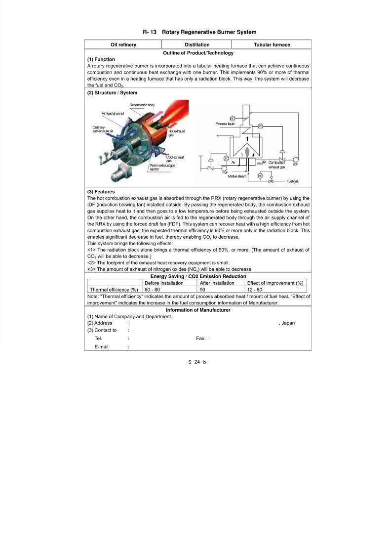
(1) Function
A rotary regenerative burner is incorporated into a tubular heating furnace that can achieve continuouscombustion and continuous heat exchange with one burner. This implements 90% or more of thermal
efficiency even in a heating furnace that has only a radiation block. This way, this system will decrease
the fuel and CO2.
(2) Structure / System
(3) Features
The hot combustion exhaust gas is absorbed through the RRX (rotary regenerative burner) by using the
IDF (induction blowing fan) installed outside. By passing the regenerated body, the combustion exhaustgas supplies heat to it and then goes to a low temperature before being exhausted outside the system.
On the other hand, the combustion air is fed to the regenerated body through the air supply channel of
the RRX by using the forced draft fan (FDF). This system can recover heat with a high efficiency from hot
combustion exhaust gas; the expected thermal efficiency is 90% or more only in the radiation block. This
enables significant decrease in fuel, thereby enabling CO2 to decrease.
This system brings the following effects:
<1> The radiation block alone brings a thermal efficiency of 90%. or more. (The amount of exhaust of
CO2 will be able to decrease.)
<2> The footprint of the exhaust heat recovery equipment is small.
<3> The amount of exhaust of nitrogen oxides (NOx) will be able to decrease.
Energy Saving / CO2 Emission Reduction
Before installation After installation Effect of improvement (%)
Thermal efficiency (%) 60 - 80 90 12 - 50
Note: "Thermal efficiency" indicates the amount of process absorbed heat / mount of fuel heal. "Effect of
improvement" indicates the increase in the fuel consumption information of Manufacturer.