38
1 5th PIANC YP-Com (BTV) Friday, May 8 – Ghent – Port of Ghent Visitors’ centre 11:30 – 12:00 Ir. Bart Moens

1
5th PIANC YP-Com (BTV)
Friday, May 8 – Ghent – Port of Ghent Visitors’ centre
11:30 – 12:00
Ir. Bart Moens

2
State-of-the-art
Cable Installation Projects

3
Presentation Overview
Introduction
Case study: Race Bank Project
State-of-the-art project references

4
1. INTRODUCTION
TECHNICAL

5
Company Overview
International maritime contractor operating over 75 vessels
Founded as Civil Engineering Contractor in 1938
100% owned and managed by the De Nul family
Belgium based with offices worldwide
Principal business: carry out projects with vessels owned
and operated by company
2014 turnover
Euro 2.1 billion
5,725 employees
fleet
75 vessels

6
What we do...

7
International submarine cable from England to France in 1850 - CLV “Goliath”

8
State-of-the-art
Cable installation vessels

9
Cable Laying Services
‘Willem de Vlamingh’
2011: Built as Rock Installation
Vessel (FPV, SSDV)
2013: Reconfigurated to Cable
Laying Vessel (CLV)
‘Isaac Newton’
March 2015: Launched at
Uljanik Shipyard (Pula, Croatia)
August 2015: Delivery

10

11
• Cable lay (5,400mT)
• Rock placing (6,000mT; FPV/SSDV)
Potential layouts:
Multi-purpose DP2 vessel
Cable Installation Vessel – ‘Willem de Vlamingh’
• Trencher support
• Combination

12
Cable Installation Vessel – ‘Isaac Newton’
Multi-purpose DP2 vessel: •Cable lay (7,400mT + 4,500mT)
•Rock placing (7,000mT + 3,000mT)
•Trencher support
•Combination
Potential layouts:

13
Cable Installation Vessel – ‘Isaac Newton’ Deadweight 10,500 t
Length 138.0 m
Breadth 32.0 m
Draught loaded 7.0 m
Dynamic Positioning DP2
Propulsion 2 x 3,000 kW
Bow thruster 2 x 1,500 kW
Total power 12,000 kW
Speed 12.0 knots
Accommodation 75
Unique patented cable
loading design which
allows to load,
transport and install a
maximum of 10,500
tonnes of cable in one
single length divided
over two turntables

14

15
1. CASE STUDY
TECHNICAL

16
UK –Race Bank (ROW) Project 08/05/2015

17
ROW01 project includes installation of
approx. 2 x 71km 220kV submarine
cable systems with integrated fibre optic
cable between the offshore substation
and the transition joint onshore and
installation of a 6km long link cable.
2016
Circuit 1 and 2 – intertidal (2 x 8 km)
Circuit 1 - Offshore Section (63km)
2017
Circuit 2 – Offshore (63 km)
Circuit 3 - Offshore interlink cable (6 km)

18
Cable loading, transport and installation
Activity Vessel
1 2 x 8 km (2016) Willem De Vlamingh
2 1 x 63 km (2016) Isaac Newton
3 1 x 63 km (2017) Isaac Newton
4 LINK (6 km) (2017) Isaac Newton
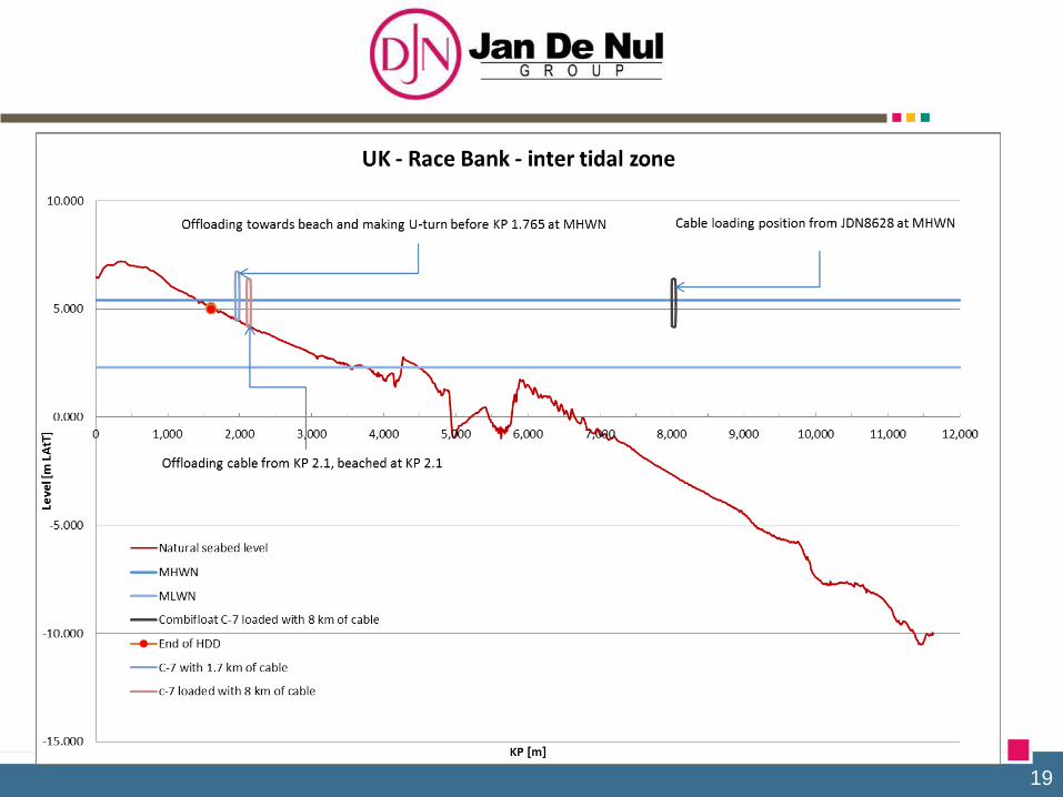
19

20
Site visit
Marsh: L1: Vegetation layer
L2: Organic layer
L3: Saturated soil
Mud flats: L1: missing
L2: missing
L3: Saturated soil
L1
L2
L3

21
Effect
vegetation
Effect roots in
subsoil Saturated soil
Marsh Mud flats

22
Conclusion: available measurement of the soil conditions
Very low soil strength
Most of the measurements are irrelevant for vegetation and organic layer
Other tests are required as basis for detailed design.
What do we want to know?
1.What is the maximal TRACTION possible without damaging the soil structure?
2.What is the maximal BEARING CAPACITY of the soil/vegetation?
3.What is the minimal required traction force to DRAG the tools (Plough / Chain cutter)?
What is JDN-method for testing?
What can we measure and are the scaling laws reliable?
23
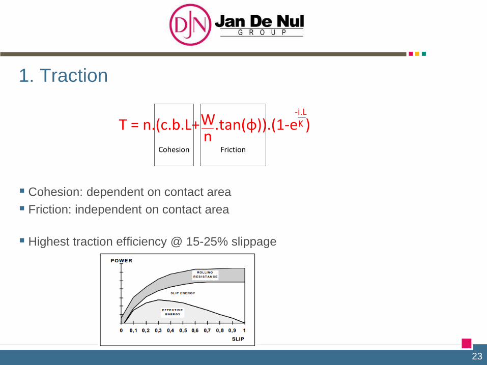
1. Traction
Cohesion: dependent on contact area
Friction: independent on contact area
Highest traction efficiency @ 15-25% slippage
T = n.(c.b.L+ .tan(φ)).(1-e )-i.LKW
nFrictionCohesion

24
1. Traction
Conclusion theory traction: Marsh
Vegetation => cohesion will help us to increase traction
Limits in vegetation: what is the maximal force which can be applied before the
vegetation is damaged?
The larger the tracks, the better the cohesion factor
We want to avoid friction to increase traction as this enhances RUTTING
The lower the weight, the lower the risk for rutting
Mud flats
Cohesion is probably none existing
Friction based on weight will help us to increase traction
Limits in weight: bearing capacity => using pulling wire from beached pontoon to pull the
machine over the mud flats, only using the tracks for bearing the weight of the machine
The larger the tracks, the better the bearing capacity
Artic track design helps to maximise the available contact surface,
while ridgid tracks cause load peaks damaging the soil.

25
1. Traction
Validation Traction :
Field test to determine : Grouser plate test
Prototype: JDN swamp excavator
c & φ

26
2. Bearing capacity TECHNICAL
Working principle test Bearing capacity
Marsh: minimum ground pressure in order not to damage the vegetation layer
Mud flat: first indication gives a good bearing capacity

27
3. Drag tool TECHNICAL
Working principle test Drag tool
Static situation: YIELD force
N: dimensionless factors depending on tool geometry => a priori unknown
Most dominant factor in this equation is soil density
Yield force ~ width tool b
Yield force ~ (depth tool h)²
Dynamic situation: DRAG force
CD: dimensionless drag coefficient depending on tool geometry => a priori unknown
Drag force ~ (velocity tool v)²
Drag force ~ projected area A = > Drag force ~ depth tool
General remark: JDN estimates the plough generates a higher drag force
than the chain cutter
F =(ρ.h².Nρ + c.h.Nc + p.h.Np + cα.h.Ncα).b
Soil density CohesionGround pressure
Adhesion soil - tool

28
3. Drag tool TECHNICAL
Validation: Drag force: prototype V-shaped plough Standard
Width legs adapted to with export cable
V-shaped plough with one leg, cfr. design Mastenbroek
Adhesion between soil and plough: anti-stick layer or greasing with water
Vibrating V-plough
Location tests?
2 potential locations:
Belgium & The Netherlands
Timing tests?
Q4 2014
Prototype: JDN swamp excavator in combination with V-shaped plough

29
SALT MARSH TRENCHER

30
INTER TIDAL FLAT TRENCHER

31
Shallow pontoon for installation of intertidal cable

32
Cable loading, transport and installation
Activity Vessel
1 2 x 8 km (2016) Willem De Vlamingh
2 1 x 63 km (2016) Isaac Newton
3 1 x 63 km (2017) Isaac Newton
4 LINK (6 km) (2017) Isaac Newton

33
CABLE LAYING VESSELS: WILLEM DE VLAMINGH (2 x 8 km) DP-2, 5,400 T ISAAC NEWTON (2 x 63 + 6 km) DP-2, beaching, 7,400 T & 4,500 T PONTOON (2 x 8 km) 6p mooring + spuds

34
POST-LAY TRENCHING WITH UTV1200 and TSV VESSEL POMPEÏ

35
POST-LAY TRENCHING WITH UTV1200 and TSV VESSEL POMPEÏ

36
3. PROJECT REFERENCES
TECHNICAL

37
38
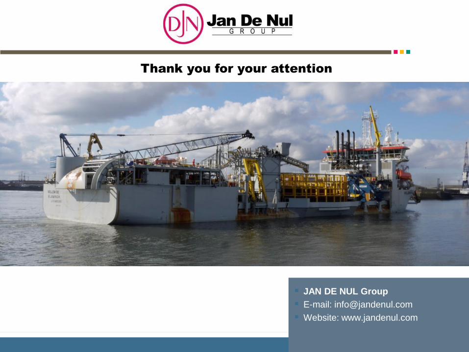
JAN DE NUL Group
E-mail: [email protected]
Website: www.jandenul.com
Thank you for your attention


