CHAPTER 16-1 Cisco Wireless Control System Configuration Guide OL-19041-01 16 Alarms and Events This chapter describes the type of events and alarms reported, how to view alarms and events by product or entity and severity, and how to view IDS signature attacks. It contains these sections: • Using the Alarm Summary, page 16-1 • Monitoring Alarms, page 16-5 • Viewing Alarm Details, page 16-9 • Alarm and Event Dictionary, page 16-21 An event is an occurrence or detection of some condition in and around the network. For example, it can be a report about radio interference crossing a threshold, the detection of a new rogue access point, or a controller rebooting. Events are not generated by a controller for each and every occurrence of a pattern match. Some pattern matches must occur a certain number of times per reporting interval before they are considered a potential attack. The threshold of these pattern matches is set in the signature file. Events can then generate alarms which further can generate e-mail notifications if configured as such. An alarm is a WCS response to one or more related events. If an event is considered of high enough severity (critical, major, minor, or warning), the WCS raises an alarm until the resulting condition no longer occurs. For example, an alarm may be raised while a rogue access point is detected, but the alarm terminates after the rogue has not been detected for several hours. One or more events can result in a single alarm being raised. The mapping of events to alarms is their correlation function. For example, some IDS events are considered to be network wide so all events of that type (regardless of which access point the event is reported from) map to a single alarm. On the other hand, other IDS events are client-specific. For these, all events of that type for a specific client MAC address map to an alarm which is also specific for that client MAC address, regardless of whether multiple access points report the same IDS violation. If the same kind of IDS violation takes place for a different client, then a different alarm is raised. A WCS administrator currently has no control over which events generate alarms or when they time out. On the controller, individual types of events can be enabled or disabled (such as management, SNMP, trap controls, etc.). Using the Alarm Summary When WCS receives an alarm message from a controller, it displays an alarm indicator at the top of the WCS window (see Figure 16-1).
Transcript
OL-19041-01
C H A P T E R 16
Alarms and Events
This chapter describes the type of events and alarms reported, how to view alarms and events by product or entity and severity, and how to view IDS signature attacks. It contains these sections:
• Using the Alarm Summary, page 16-1
• Monitoring Alarms, page 16-5
• Viewing Alarm Details, page 16-9
• Alarm and Event Dictionary, page 16-21
An event is an occurrence or detection of some condition in and around the network. For example, it can be a report about radio interference crossing a threshold, the detection of a new rogue access point, or a controller rebooting.
Events are not generated by a controller for each and every occurrence of a pattern match. Some pattern matches must occur a certain number of times per reporting interval before they are considered a potential attack. The threshold of these pattern matches is set in the signature file. Events can then generate alarms which further can generate e-mail notifications if configured as such.
An alarm is a WCS response to one or more related events. If an event is considered of high enough severity (critical, major, minor, or warning), the WCS raises an alarm until the resulting condition no longer occurs. For example, an alarm may be raised while a rogue access point is detected, but the alarm terminates after the rogue has not been detected for several hours.
One or more events can result in a single alarm being raised. The mapping of events to alarms is their correlation function. For example, some IDS events are considered to be network wide so all events of that type (regardless of which access point the event is reported from) map to a single alarm. On the other hand, other IDS events are client-specific. For these, all events of that type for a specific client MAC address map to an alarm which is also specific for that client MAC address, regardless of whether multiple access points report the same IDS violation. If the same kind of IDS violation takes place for a different client, then a different alarm is raised.
A WCS administrator currently has no control over which events generate alarms or when they time out. On the controller, individual types of events can be enabled or disabled (such as management, SNMP, trap controls, etc.).
Using the Alarm SummaryWhen WCS receives an alarm message from a controller, it displays an alarm indicator at the top of the WCS window (see Figure 16-1).
16-1Cisco Wireless Control System Configuration Guide
Chapter 16 Alarms and Events Using the Alarm Summary
Note The Administration > Settings > Alarms page has a Hide Acknowledged Alarms check box. You must uncheck the preference of hiding acknowledged alarms if you want acknowledged alarms to show on the WCS Alarm Summary and alarms lists window. By default, acknowledged alarms are not shown.
Critical (red), Major (orange) and Minor (yellow) alarms are shown in the alarm dashboard, left -to-right.
Figure 16-1 WCS Alarm Summary
Alarms indicate the current fault or state of an element that attention, and they are usually generated by one or more events. The alarm can be cleared but the event remains.
Note Alarm counts refresh every 15 seconds.
Note If an alarm is acknowledged, it does not appear on the alarm summary window by default. To change this setting, go to Administration > Settings > Alarms and deselect the Hide acknowledged alarms check box.
Alarms are color coded as follows:
• Red—Critical Alarm
• Orange—Major Alarm
• Yellow—Minor Alarm
The Alarm Summary displays the number of current critical, major, and minor alarms (see Figure 16-2).
16-2Cisco Wireless Control System Configuration Guide
OL-19041-01
Chapter 16 Alarms and Events Using the Alarm Summary
Figure 16-2 Alarm Summary Page for WCS
Click the alarm count number link in the Alarm Summary window to view the Monitor > Alarms window for these alarms.
Click the blue down arrow in the Alarm Summary window to expand the alarm summary (see Figure 16-3).
16-3Cisco Wireless Control System Configuration Guide
OL-19041-01
Chapter 16 Alarms and Events Using the Alarm Summary
Figure 16-3 Open Summary Alarm
The expanded summary includes alarm counts for the following:
• Access Points—Displays counts for AP alarms such as AP Disassociated from controller, Thresholds violation for Load, Noise or Interference, AP Contained as Rogue, AP Authorization Failure, AP regulatory domain mismatch, or Radio card Failure. See the “Monitoring Alarms” section on page 16-5 for more information.
• Controllers—Displays counts for controller alarms, such as reachability problems from WCS and other controller failures (fan failure, POE controller failure, AP license expired, link down, temperature sensor failure, and low temperature sensed). See the “Monitoring Alarms” section on page 16-5 for more information.
• Coverage Hole—Displays counts for coverage hole alarms generated for access points whose clients are not having enough coverage set by thresholds. See the “Monitoring Maps Overview” section on page 5-2 for more information.
• Malicious AP—Displays counts for malicious rogue access points alarms. See the “Monitoring Rogue Access Point Alarms” section on page 16-10 for more information.
• Mesh Links—Displays counts for mesh link alarms, such as poor SNR, console login, excessive parent change, authorization failure, or excessive association failure. See the “Monitoring Alarms” section on page 16-5 for more information.
• Mobility—Displays counts for location alarms such as reachability problems from WCS and location notifications (In/Out Area, Movement from Marker, or Battery Level). See the “Monitoring Alarms” section on page 16-5 for more information.
• Security—Displays counts for security alarms such as Signature Attacks, AP Threats/Attacks, and Client Security Events. See the “Monitoring Alarms” section on page 16-5 for more information.
• Unclassified AP—Displays counts for unclassified rogue access point alarms. See the “Monitoring Rogue Access Point Alarms” section on page 16-10 for more information.
• WCS—Displays counts for WCS alarms such as e-mail failures and license violation alarms.
Customizing Alarm Summary ResultsIf you click Edit View from the Alarm Summary window (shown in Figure 16-2), you can customize which results you want to appear in the Alarm Summary window.
Column names appear in one of the following lists:
• Hide Information—Lists columns that do not appear in the table. The Hide button points to this list.
• View Information—Lists columns that do appear in the table. The Show button points to this list.
16-4Cisco Wireless Control System Configuration Guide
OL-19041-01
Chapter 16 Alarms and Events Monitoring Alarms
To display a column in a table, click it in the Hide Information list, then click Show. To remove a column from a table, click it in the View Information list, then click Hide. You can select more than one column by holding down the Shift or Control key.
To change the position of a column in the View Information list, click it, then click Up or Down. The higher a column is in the list, the farther left it appears in the table.
The Alarm Summary items to choose from are as follows:
• Owner
• Date/Time
• Message
• Acknowledged
• Category
• Condition
Monitoring AlarmsThis section provides information on the following:
• Monitoring Alarm Overview, page 16-5
• Using Edit View for Alarms, page 16-8
• Viewing Alarm Details, page 16-9
• Monitoring Rogue Access Point Alarms, page 16-10
• Using Advanced Search, page 16-12
• Viewing Rogue Access Point Details, page 16-14
• Acknowledging Alarms, page 16-16
• Monitoring Adhoc Rogue Alarms, page 16-16
• Rogue Access Point Location, Tagging, and Containment, page 16-18
• Monitoring Rogue Alarm Events, page 16-20
• Monitoring E-mail Notifications, page 16-20
Monitoring Alarm OverviewChoose Monitor > Alarms to open the Alarms window. This window summarizes the controller alarms (see Figure 16-4).
Note You can search for a specific alarm or type of alarm by using the WCS search feature. Refer to “Using the Search Feature” section on page 2-28 for more information on searching for an alarm or alarm type.
16-5Cisco Wireless Control System Configuration Guide
OL-19041-01
Chapter 16 Alarms and Events Monitoring Alarms
Figure 16-4 Monitor Alarms Window
This window displays a table of logged alarms. For more information, see Table 16-1.
16-6Cisco Wireless Control System Configuration Guide
OL-19041-01
Chapter 16 Alarms and Events Monitoring Alarms
When there are multiple alarm pages, the page numbers appear at the top of the page with a scroll arrow on each side. Use this to view additional alarms.
To add, remove, or reorder columns in the table, click Edit View to go to the Edit View window.
Table 16-1 Monitor Alarms Window
Parameter Description
(Check box) Enables you to select one or more alarms. You can take action on selected alarms using the Select a command drop-down list.
Severity Displays the alarm’s level of severity ranging from critical to minor.
• Red circle—Critical
• Orange downward triangle—Major
• Yellow upward triangle—Minor
Failure Source Indicates the device that triggered the alarm.
Note When you move your mouse cursor over an individual failure source, additional information regarding the failure and its location displays. The same information appears in the Message column.
Owner Displays the name of the person to whom this alarm is assigned, if one was entered.
Date/Time Displays the date and time that the alarm occurred.
Message Indicates the reason for the alarm.
Acknowledged Displays whether or not the alarm is acknowledged by the user.
Category Displays the alarm’s assigned category such as rogue AP, controller, switch, and security.
This column does not appear by default. You can add this column to the table in the Edit View window. To go to the Edit View window, click Edit View. See the “Using Edit View for Alarms” section on page 16-8 for more information.
Condition Displays the current condition that caused the alarm.
This column does not appear by default. You can add this column to the table in the Edit View window. To go to the Edit View window, click Edit View. See the “Using Edit View for Alarms” section on page 16-8 for more information.
16-7Cisco Wireless Control System Configuration Guide
OL-19041-01
Chapter 16 Alarms and Events Monitoring Alarms
Select a Command Menu
Using the Select a command drop-down list, you can make the following changes to the selected alarms:
• Assign to me—Assign the selected alarms to the current user.
• Unassign—Unassign the selected alarms.
• Delete—Delete the selected alarms.
• Clear—Clear the selected alarms.
• Acknowledge—You can acknowledge the alarm to prevent it from showing up in the Alarm Summary window. The alarm remains in WCS and you can search for all Acknowledged alarms using the alarm search functionality.
• Unacknowledge—You can choose to unacknowledge an already acknowledged alarm.
• Email Notification—Opens the All Alarms > Email Notification page where you can view and configure e-mail notifications.
To make a change to a selected alarm, follow these steps:
Step 1 Select an alarm by checking the check box.
Step 2 From the command drop-down list, select a command.
Step 3 Click Go.
Using Edit View for AlarmsThe Edit View window allows you to add, remove, or reorder columns in the alarms table (see Figure 16-5).
Figure 16-5 Edit View Window
To edit the available columns in the alarms table, follow these steps:
16-8Cisco Wireless Control System Configuration Guide
OL-19041-01
Chapter 16 Alarms and Events Viewing Alarm Details
Step 1 Choose Monitor > Alarms.
Step 2 Click Edit View.
Step 3 To add an additional column to the alarms table, click to highlight the column heading in the left column. Click Show to move the heading to the right column. All items in the right column are displayed in the alarms table.
Step 4 To remove a column from the alarms table, click to highlight the column heading in the right column. Click Hide to move the heading to the left column. Not all items in the left column appear in the alarms table.
Step 5 Use the Up/Down buttons to specify the order in which the information appears in the table. Highlight the desired column heading and click Up or Down to move it higher or lower in the current list.
Step 6 Click Reset to restore the default view.
Viewing Alarm DetailsFrom the Monitor > Alarms window, click an item under Failure Source to access the alarms details page (see Figure 16-6).
Figure 16-6 Alarm Details Window
This window provides the following information (Table 16-2):
Table 16-2 General Parameters
Parameter Description
Failure Source Device that generated the alarm.
Owner Name of person to which this alarm is assigned, or blank.
Acknowledged Displays whether or not the alarm is acknowledged by the user.
16-9Cisco Wireless Control System Configuration Guide
OL-19041-01
Chapter 16 Alarms and Events Viewing Alarm Details
Note The General information may vary depending on the type of alarm. For example, some alarm details may include location and switch port tracing information.
• Annotations—Enter any new notes in this box and click Add to update the alarm. Notes appear in the “Annotations” display area.
• Messages—Displays information about the alarm.
• Audit Report—Click to view config audit alarm details. This report is only available for Config Audit alarms.
Configuration audit alarms are generated when audit discrepancies are enforced on config groups.
Note If enforcement fails, a critical alarm is generated on the config group. If enforcement succeeds, a minor alarm is generated on the config group.The alarms have links to the audit report where you can view a list of discrepancies for each controller.
• Event History—Opens you to the Monitoring Rogue Alarm Events page to view events for this alarm. When there are multiple alarm pages, the page numbers appear at the top of the page with a scroll arrow on each side. Use these scroll arrows to view additional alarms.
Monitoring Rogue Access Point AlarmsRogue access point radios are unauthorized access points detected by one or more access points.
To open the Rogue AP Alarms page, do one of the following:
• Search for rogue Access Points. See the “Using Advanced Search” section on page 16-12 for more information about the search feature.
• From the WCS Home Page, select the Security tab. This window displays all the rogue access points detected in the past hour and the past 24 hours. Click the rogue access point number to view the rogue access point alarms.
Category The category of the alarm (for example, AP, Rogue AP, or Security)
Created Month, day, year, hour, minute, second, AM or PM alarm created.
Modified Month, day, year, hour, minute, second, AM or PM alarm last modified.
Generated By Device that generated the alarm.
Severity Level of security: Critical, Major, Minor, Warning, Clear, Info, Color coded.
Previous Severity Critical, Major, Minor, Warning, Clear, Info. Color coded.
Table 16-2 General Parameters
Parameter Description
16-10Cisco Wireless Control System Configuration Guide
OL-19041-01
Chapter 16 Alarms and Events Viewing Alarm Details
• Click the Malicious AP number link in the Alarm Summary box. See the “Using the Alarm Summary” section on page 16-1 for more information.
Note If there are multiple alarm pages, the page numbers appear at the top of the page with a scroll arrow on each side. Use this to view additional alarms.
The Rogue AP Alarms page contains the following parameters:
Note The alarm remains in WCS, and you can search for all Acknowledged alarms using the alarm search functionality.
Select a Command
Select one or more alarms by checking their respective check boxes, select one of the following commands from the Select a Command drop-down menu, and click Go.
• Assign to me—Assign the selected alarms to the current user.
• Unassign—Unassign the selected alarms.
• Delete—Delete the selected alarms.
• Clear—Clear the selected alarms.
Table 16-3 Rogue Access Point Alarms
Parameter Description
Check box Select the alarms on which you want to take action.
Severity Indicates the severity of the alarm: Critical, Major, Minor, Clear.
Rogue MAC Address Indicates the MAC address of the rogue access points. See Monitor Alarms > Rogue AP Details.
Vendor Rogue access point vendor name or Unknown.
Classification Type Malicious, Friendly, or Unclassified.
Radio Type Indicates the radio type for this rogue access point.
Strongest AP RSSI Indicates the which signal strength indicator that was the strongest for this WCS (including all detecting access points for all controllers and across all detection times).
No. of Rogue Clients Indicates the number of rogue clients associated to this access point.
Date/Time Indicates the date and time that the alarm occurred.
State Indicates the state of the alarm. Includes Alert, Known or Removed.
SSID Indicates the service set identifier being broadcast by the rogue access point radio. It is blank if SSID is not being broadcast.
Map Location Indicates the map location for this rogue access point.
Acknowledged Displays whether or not the alarm is acknowledged by the user.
16-11Cisco Wireless Control System Configuration Guide
OL-19041-01
Chapter 16 Alarms and Events Viewing Alarm Details
• Acknowledge—Acknowledge the alarm to prevent it from showing up in the Alarm Summary window. See the “Acknowledging Alarms” section on page 16-16 for more information.
Note The alarm remains in WCS and you can search for all Acknowledged alarms using the alarm search functionality.
• Unacknowledge—Unacknowledge an already acknowledged alarm.
• E-mail Notification—Opens the All Alarms > E-mail Notification page where you can view and configure e-mail notifications. See Monitor Alarms > E-mail Notification for more information.
Caution Attempting to contain a rogue access point may lead to legal consequences. When you select any of the AP Containment commands and click GO, a message “Containing a Rogue AP may have legal consequences. Do you want to continue?” appears. Click OK if you are sure or click Cancel if you do not wish to contain any access points.
Using Advanced SearchWhen the access points on your wireless LAN are powered up and associated with controllers, WCS immediately starts listening for rogue access points. When a controller detects a rogue access point, it immediately notifies WCS, which creates a rogue access point alarm.
Follow these steps to find rogue access point alarms using Advanced Search.
Step 1 Click Advanced Search. It is in the top right-hand corner of virtually any WCS window.
Step 2 Choose Rogue Client from the Search Category drop-down menu.
Step 3 (optional) You can filter the search even further with the other search criteria if desired.
Step 4 Click Search.
Step 5 The list of rogue clients appears (see Figure 16-7).
Figure 16-7 Rogue Clients Window
Step 6 Choose a rogue client by clicking a client MAC address. The Rogue Client detail window appears (see Figure 16-8).
16-12Cisco Wireless Control System Configuration Guide
OL-19041-01
Chapter 16 Alarms and Events Viewing Alarm Details
Figure 16-8 Rogue Client Detail Window
16-13Cisco Wireless Control System Configuration Guide
OL-19041-01
Chapter 16 Alarms and Events Viewing Alarm Details
Step 7 To modify the alarm, choose one of these commands from the Select a command drop-down menu and click Go.
• Set State to ‘Unknown-Alert’—Tags the ad hoc rogue as the lowest threat, continues to monitor the ad hoc rogue, and turns off containment.
• 1 AP Containment through 4 AP Containment—Indicates the number of access points (1-4) in the vicinity of the rogue unit that send dauthenticate and disassociate messages to the client devices that are associated to the rogue unit.
• Map (High Resolution)—Displays the current calculated rogue location on the Maps > Building Name > Floor Name page.
• Location History—Displays the history of the rogue client location based on RF fingerprinting.
Note The client must be detected by an MSE for the location history to appear.
Configuring Alarm SeverityThe Settings > Severity Configuration page allows you to change the severity level for newly generated alarms.
Note Existing alarms remain unchanged.
To reconfigure the severity level for a newly generated alarm, follow these steps:
Step 1 Choose Administration > Settings.
Step 2 From the left sidebar menu, select Severity Configuration.
Step 3 Select the check box of the alarm condition whose severity level you want to change.
Step 4 From the Configure Security Level drop-down menu, select from the following severity levels:
• Critical
• Major
• Minor
• Warning
• Informational
• Reset to Default
Step 5 Click Go.
Step 6 Click OK to confirm the change or Cancel to leave the security level unchanged.
Viewing Rogue Access Point DetailsAlarm event details for each rogue access point are available from the Rogue AP Alarms page.
16-14Cisco Wireless Control System Configuration Guide
OL-19041-01
Chapter 16 Alarms and Events Viewing Alarm Details
Follow these steps to view alarm events for a rogue access point radio.
Step 1 From the Rogue AP Alarms page, click an item under Rogue MAC Address.
This page displays alarm events for a rogue access point radio. Rogue access point radios are unauthorized access points detected by access points. The following information is available:
• General—
– Rogue MAC Address—MAC address of the rogue access points.
– Vendor—Rogue access point vendor name or Unknown.
– Rogue Type—Indicates the rogue type such as AP.
– On Network—Indicates whether or not the rogue access point is located on the network.
– Owner—Indicates the owner or is left blank.
– Acknowledged—Indicates whether or not the alarm is acknowledged by the user.
– Classification Type—Malicious, Friendly, or Unclassified.
– State—Indicates the state of the alarm: Alert, Known, or Removed.
– SSID—Service Set Identifier being broadcast by the rogue access point radio. (Blank if SSID is not broadcast.)
– Channel Number—Indicates the channel of the rogue access point.
– Containment Level—Indicates the containment level of the rogue access point or Unassigned.
– Radio Type—Indicates the radio type for this rogue access point.
– Strongest AP RSSI—Indicates the strongest received signal strength indicator in dBm.
– No. of Rogue Clients—Indicates the number of rogue clients associated to this access point.
– Created—Indicates when the alarm event was created.
– Modified—Indicates when the alarm event was modified.
– Generated By—Indicates how the alarm event was generated.
– Severity—The severity of the alarm: Critical, Major, Minor, Clear. Color coded.
– Previous Severity—The previous severity of the alarm: Critical, Major, Minor, Clear. Color coded.
– Event Details—Click to open the Monitor > Events windows
– Switch Port Trace Status—Indicates the switch port trace status. Refer to the “Switch Port Trace” section on page 18-51 or the “Using Switch Port Tracing” section on page 10-49 for additional information.
• Switch Port Tracing Details—Provides the most recent switch port tracing details. To view additional trace details, use the Click here for more details... link.
• Rogue Client—Lists rogue clients for this access point including the client MAC address, the last date and time the client was heard, and the current client status.
• Message—Describes the alarm.
• Annotations—Lists current notes regarding this rogue access point. To add a new note, click New Annotation. Type the note and click Post to save and display the note or Cancel to close the window without saving the note.
• Location Notifications—Displays the number of location notifications logged against the client. Clicking a link displays the notifications.
16-15Cisco Wireless Control System Configuration Guide
OL-19041-01
Chapter 16 Alarms and Events Viewing Alarm Details
• Location—Provides location information, if available.
Acknowledging AlarmsYou may want to remove certain alarms from the Alarms List. For example, if you are continuously receiving an interference alarm from a certain access point on the 802.11g interface, you may want to stop that access point from being counted as an active alarm on the Alarm Summary window or any alarms list. In this scenario, you can find the alarm for the 802.11g interface in the Alarms list, click the check box, and choose Acknowledge from the Select a command drop-down list.
Now if the access point generates a new violation on the same interface, WCS will not create a new alarm, and the Alarm Summary window shows no new alarms. However, if the interference violation is created on another interface, such as 802.11a, a new alarm is created.
Any alarms, once acknowledged, will not show up on either the Alarm Summary window or any alarm list page. Also, no e-mails are generated for these alarms after you have marked them as acknowledged.
By default, acknowledged alarms cannot be found with any search criteria. To change this default, go to the Administration > Settings > Alarms window and disable the Hide Acknowledged Alarms preference.
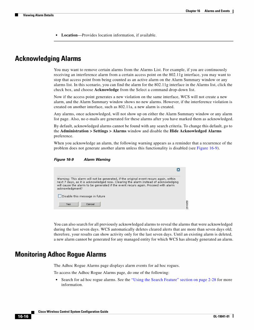
When you acknowledge an alarm, the following warning appears as a reminder that a recurrence of the problem does not generate another alarm unless this functionality is disabled (see Figure 16-9).
Figure 16-9 Alarm Warning
You can also search for all previously acknowledged alarms to reveal the alarms that were acknowledged during the last seven days. WCS automatically deletes cleared alerts that are more than seven days old; therefore, your results can show activity only for the last seven days. Until an existing alarm is deleted, a new alarm cannot be generated for any managed entity for which WCS has already generated an alarm.
Monitoring Adhoc Rogue AlarmsThe Adhoc Rogue Alarms page displays alarm events for ad hoc rogues.
To access the Adhoc Rogue Alarms page, do one of the following:
• Search for ad hoc rogue alarms. See the “Using the Search Feature” section on page 2-28 for more information.
16-16Cisco Wireless Control System Configuration Guide
OL-19041-01
Chapter 16 Alarms and Events Viewing Alarm Details
• From the WCS Home Page, select the Security tab. This window displays all the ad hoc rogues detected in the past hour and the past 24 hours. Click the ad hoc rogue number to view the ad hoc rogue alarms.
If there are multiple alarm pages, the page numbers appear at the top of the page with a scroll arrow on each side. Use this to view additional alarms.
The Adhoc Rogue Alarms page contains the following parameters:
Monitoring Adhoc Rogue DetailsAlarm event details for each ad hoc rogue are available from the Adhoc Rogue Alarms page.
Follow these steps to view the alarm events for an ad hoc rogue radio.
Step 1 From the Adhoc Rogue Alarms page, click an item under Rogue MAC Address.
This page displays alarm events for a rogue access point radio. Rogue access point radios are unauthorized access points detected by Cisco lightweight access points. The following information is available:
• General—
– Rogue MAC Address—Media Access Control address of the ad hoc rogue.
– Vendor—Ad hoc rogue vendor name or Unknown.
Table 16-4 Adhoc Rogue Alarm Parameters
Parameter Description
Check box Choose the alarms on which you want to take action.
Severity The severity of the alarm including Critical, Major, Minor, and Clear. These severity levels are color-coded.
Adhoc Rogue MAC Address Indicates the MAC address of the ad hoc rogue.
Vendor Indicates the ad hoc rogue vendor name or Unknown.
Classification Type Indicates the classification type of the ad hoc rogue including malicious, friendly, or unclassified.
Radio Type Indicates this ad hoc rogue’s radio type.
Strongest AP RSSI Indicates the strongest received signal strength indicator in dBm.
No. of Rogue Clients Indicates the number of rogue clients associated to this ad hoc rogue.
Owner Indicates the owner of the ad hoc rogue.
Date/Time Indicates the date and time that the alarm occurred.
State Indicates the current state of the alarm including alert, known, or removed.
SSID Service Set Identifier that is being broadcast by the ad hoc rogue radio. It is blank if there is no broadcast.
Map Location Indicates the map location for this ad hoc rogue.
Acknowledged Displays whether or not the alarm is acknowledged by the user.
16-17Cisco Wireless Control System Configuration Guide
OL-19041-01
Chapter 16 Alarms and Events Viewing Alarm Details
– On Network—Indicates whether or not the ad hoc rogue is located on the network.
– Owner—Indicates the owner or left blank.
– Acknowledged—Indicates whether or not the alarm is acknowledged by the user.
– Classification Type—Malicious, Friendly, or Unclassified.
– State—Indicates the state of the alarm: Alert, Known, or Removed.
– SSID—Service Set Identifier being broadcast by the ad hoc rogue radio. (Blank if SSID is not broadcast.)
– Channel Number—Indicates the channel of the ad hoc rogue.
– Containment Level—Indicates the containment level of the ad hoc rogue or Unassigned.
– Radio Type—Indicates the radio type for this ad hoc rogue.
– Strongest AP RSSI—Indicates the strongest received signal strength indicator in dBm.
– No. of Rogue Clients—Indicates the number of rogue clients associated to this ad hoc.
– Created—Indicates when the alarm event was created.
– Modified—Indicates when the alarm event was modified.
– Generated By—Indicates how the alarm event was generated.
– Severity—The severity of the alarm: Critical, Major, Minor, Clear. Color coded.
– Previous Severity—The previous severity of the alarm: Critical, Major, Minor, Clear. Color coded.
• Annotations—Enter any new notes in this box and click Add to update the alarm.
• Message—Displays descriptive information about the alarm.
• Help—Displays the latest information about the alarm.
• Event History—Click to access the Monitor Alarms > Events page.
• Annotations—Lists existing notes for this alarm.
Rogue Access Point Location, Tagging, and ContainmentWhen the Cisco Unified Wireless Network Solution is monitored using WCS, WCS generates the flags as rogue access point traps and displays the known rogue access points by MAC address. The operator can then display a map showing the location of the access points closest to each rogue access point. The next step is to mark them as Known or Acknowledged rogue access points (no further action), Alert rogue access points (watch for and notify when active), or Contained rogue access points (have between one and four access points discourage rogue access point clients by sending the clients deauthenticate and disassociate messages whenever they associate with the rogue access point).
This built-in detection, tagging, monitoring, and containment capability enables system administrators to take appropriate action:
• Find rogue access points.
• Receive new rogue access point notification, eliminating hallway scans.
• Monitor unknown rogue access points until they are eliminated or acknowledged.
• Find the closest authorized access point, making directed scans faster and more effective.
16-18Cisco Wireless Control System Configuration Guide
OL-19041-01
Chapter 16 Alarms and Events Viewing Alarm Details
• Contain rogue access points by sending their clients deauthenticate and disassociate messages from one to four access points. This containment is done for individual rogue access points by MAC address or is mandated for all rogue access points connected to the enterprise subnet.
• Tag rogue access points:
– Acknowledge rogue access points when they are outside of the LAN and do not compromise the LAN or wireless LAN security.
– Accept rogue access points when they do not compromise the LAN or wireless LAN security.
– Tag rogue access points as unknown until they are eliminated or acknowledged.
– Tag rogue access points as contained and discourage clients from disassociating with the rogue access points by having between one and four access points transmit deauthenticate and disassociate messages to all rogue access point clients. This function applies to all active channels on the same rogue access point.
Detecting Access PointsClick a Rogues alarm square in the Alarm Monitor (lower left-hand side of the screen) to access the Monitor Alarms > <failure object> page. In the Monitor Rogue AP Alarms page, click an item under Rogue MAC Address to access the Monitor Alarms > Rogue AP Details page, from the Select a command drop-down list choose Detecting APs, and click GO to access this page.
Choose Monitor > Alarms, then click New Search in the left sidebar. Choose Severity > All Severities and Alarm Category > Rogue AP, and click Go to access Monitor Alarms > <Failure Objects>.
In the Monitor Rogue AP Alarms page, click an item under Rogue MAC Address to access Monitor Alarms > Rogue AP Details. In the Monitor Alarms > Rogue - <vendor:MACaddr> page, from the Select a command drop-down list, choose Detecting APs to access this page.
This page enables you to view information about the Cisco lightweight access points that are detecting a rogue access point.
Click a list item to display data about that item:
• AP Name
• Radio
• Map Location
• SSID—Service Set Identifier being broadcast by the rogue access point radio.
• Channel Number—Which channel the rogue access point is broadcasting on.
• WEP—Enabled or disabled.
• WPA—Enabled or disabled.
• Pre-Amble—Long or short.
• RSSI—Received signal strength indicator in dBm.
• SNR—Signal-to-noise ratio.
• Containment Type—Type of containment applied from this access point.
• Containment Channels—Channels that this access point is currently containing.
16-19Cisco Wireless Control System Configuration Guide
OL-19041-01
Chapter 16 Alarms and Events Viewing Alarm Details
Monitoring Rogue Alarm EventsThe Events window enables you to review information about rogue alarm events. Events list the sequence of occurrences for an elements over a period of time.
To open the Rogue AP Alarms details window, follow these steps:
Step 1 To display the Rogue AP Alarms window, do one of the following:
• Search for rogue access points. See “Using the Search Feature” section on page 2-28 for more information about the search feature.
• From the WCS Home Page, select the Security tab. This window displays all the rogue access points detected in the past hour and the past 24 hours. Click the rogue access point number to view the rogue access point alarms.
• Click the Malicious AP number link in the Alarm Summary box. See “Using the Alarm Summary” section on page 16-1 for more information.
Step 2 From the Rogue AP Alarms window, click the Rogue MAC Address for the appropriate rogue access point. The Rogue AP Alarm details window appears.
Step 3 From the Select a command drop-down menu, click Event History.
Step 4 Click Go. The Rogue AP Events window appears.
Note Any Airlink vendors appear as Alpha.
Click the title of each column to reorder the listings:
• Severity—Color coded display of the severity of the event.
• Rogue MAC Address—Click a list item to display information about the entry.
• Vendor—Name of rogue access point manufacturer.
• Type—AP or AD-HOC.
• On Network—Whether or not the rogue access point is on the same subnet as the associated Port.
• On 802.11a—Whether or not the rogue access point is broadcasting on the 802.11a band.
• On 802.11b—Whether or not the rogue access point is broadcasting on the 802.11b/802.11g band.
• Date/Time—Date and time of the alarm.
• Classification Type—Malicious, Friendly, or Unclassified
• State—State of the alarm, such as Alert and Removed.
• SSID—Service Set Identifier being broadcast by the rogue access point radio.
Monitoring E-mail NotificationsYou can configure the delivery of e-mail notifications for specific alarm categories and severity levels.
To configure e-mail notifications, follow these steps:
Step 1 Choose Monitor > Alarms.
Step 2 From the Select a command drop-down menu, choose E-mail Notification.
16-20Cisco Wireless Control System Configuration Guide
OL-19041-01
Chapter 16 Alarms and Events Alarm and Event Dictionary
Step 3 Click an Alarm Category to edit severity level and e-mail recipients for its e-mail notifications.
Step 4 Choose the severity level check box(es) (Critical, Major, Minor, Warning) for which you want a notification sent.
Step 5 Enter the notification recipient e-mail addresses in the To text box.
Note Separate multiple e-mail addresses with commas.
Step 6 Click OK.
Step 7 Click the Enabled check box for appropriate alarm categories to activate the delivery of e-mail notifications.
Step 8 Click OK.
Monitoring Severity ConfigurationsYou can change the severity level for newly generated alarms.
Note Existing alarms remain unchanged.
To change the severity level of newly-generated alarms, follow these steps:
Step 1 Choose Administration > Setting.
Step 2 Choose Severity Configuration from the left sidebar menu.
Step 3 Choose the check box of the alarm condition for which you want to change the severity level.
Step 4 From the Configure Severity Level drop-down menu, choose the new severity level (Critical, Major, Minor, Warning, Informational, Reset to Default).
Step 5 Click Go.
Step 6 Click OK to confirm the change.
Alarm and Event DictionaryThis section describes the event and alarm notifications that the wireless LAN controller, access points, and location appliances can receive. In addition, specific actions an administrator can do to address these alarms and events are described.
Note Not all traps which are seen on the WLC GUI are supported by WCS.
16-21Cisco Wireless Control System Configuration Guide
OL-19041-01
Chapter 16 Alarms and Events Alarm and Event Dictionary
Notification FormatFor each alarm and event notification, the following information is provided:
Table 16-5 Notification Format
Field Description
Title The notification title is generally picked up from an event property file defined in the NMS.
MIB Name The MIB Name is the name of the notification as defined in the management information base (MIB). In some cases, if the event is specific only to the NMS, this field is not relevant. You can define multiple events in WCS from the same trap based on the values of the variables present in the trap. In such cases, multiple subentries appear with the same MIB Name. In addition, this field displays the value of the variable that caused WCS to generate this event.
WCS Message The WCS Message is a text string that reflects the message displayed in the WCS alarm or event browser associated with this event. Numbers such as "{0}" reflect internal WCS variables that typically are retrieved from variables in the trap. However, the order of the variables as they appear in the trap cannot be derived from the numbers.
Symptoms This field displays the symptoms associated with this event.
WCS Severity This field displays the severity assigned to this event in WCS.
Probable Causes This field lists the probable causes of the notification.
Recommended Actions This field lists any actions recommended for the administrator managing the wireless network.
16-22Cisco Wireless Control System Configuration Guide
OL-19041-01
Chapter 16 Alarms and Events Alarm and Event Dictionary
Traps Added in Release 2.0
AP_BIG_NAV_DOS_ATTACK
AP_CONTAINED_AS_ROGUE
AP_DETECTED_DUPLICATE_IP
MIB Name bsnApBigNavDosAttack.
WCS Message The AP ''{0}'' with protocol ''{1}'' receives a message with a large NAV field and all traffic on the channel is suspended. This is most likely a malicious denial of service attack.
Symptoms The system detected a possible denial of service attack and suspended all traffic to the affected channel.
WCS Severity Critical.
Probable Causes A malicious denial of service attack is underway.
Recommended Actions Identify the source of the attack in the network and take the appropriate action immediately.
MIB Name bsnAPContainedAsARogue.
WCS Message AP ''{0}'' with protocol ''{1}'' on Switch ''{2}'' is contained as a Rogue preventing service.
Symptoms An access point is reporting that it is being contained as a rogue.
WCS Severity Critical.
Probable Causes Another system is containing this access point.
Recommended Actions Identify the system containing this access point. You may need to use a wireless sniffer.
MIB Name bsnDuplicateIpAddressReported.
WCS Message AP ''{0}'' on Switch ''{3}'' detected duplicate IP address ''{2}'' being used by machine with mac address ''{1}."
Symptoms The system detects a duplicate IP address in the network that matches that assigned to an access point.
WCS Severity Critical.
Probable Causes Another device in the network is configured with the same IP address as an access point.
Recommended Actions Correct the misconfiguration of IP addresses in the network.
16-23Cisco Wireless Control System Configuration Guide
OL-19041-01
Chapter 16 Alarms and Events Alarm and Event Dictionary
AP_HAS_NO_RADIOS
AP_MAX_ROGUE_COUNT_CLEAR
AP_MAX_ROGUE_COUNT_EXCEEDED
MIB Name bsnApHasNoRadioCards.
WCS Message Not supported in WCS yet.
Symptoms An access point is reporting that it has no radio cards.
WCS Severity N/A.
Probable Causes Manufacturing fault or damage to the system during shipping.
Recommended Actions Call customer support.
MIB Name bsnApMaxRogueCountClear.
WCS Message Fake AP or other attack on AP with MAC address ''{0}'' associated with Switch ''{2}'' is cleared now. Rogue AP count is within the threshold of ''{1}'."
Symptoms The number of rogues detected by a switch (controller) is within acceptable limits.
WCS Severity Informational.
Probable Causes N/A.
Recommended Actions None.
MIB Name bsnApMaxRogueCountExceeded.
WCS Message Fake AP or other attack may be in progress. Rogue AP count on AP with MAC address ''{0}'' associated with Switch ''{2}'' has exceeded the severity warning threshold of ''{1}."
Symptoms The number of rogues detected by a switch (controller) exceeds the internal threshold.
WCS Severity Critical.
Probable Causes • There may be too many rogue access points in the network.
• A fake access point attack may be in progress.
Recommended Actions Identify the source of the rogue access points.
16-24Cisco Wireless Control System Configuration Guide
OL-19041-01
Chapter 16 Alarms and Events Alarm and Event Dictionary
Symptoms There was an SNMP authentication failure on the switch (controller).
WCS Severity Informational.
Probable Causes An incorrect community string is in use by a management application.
Recommended Actions Identify the source of the incorrect community string and correct the string within the management application.
MIB Name bsnAuthenticationFailure.
WCS Message Switch ''{0}." User authentication from Switch ''{0}'' failed for user name ''{1}'' and user type ''{2}."
Symptoms A user authentication failure is reported for a local management user or a MAC filter is configured on the controller.
WCS Severity Minor.
Probable Causes Incorrect login attempt by an admin user from the controller CLI or controller GUI, or a client accessing the WLAN system.
Recommended Actions If the user has forgotten the password, the superuser may need to reset it.
16-25Cisco Wireless Control System Configuration Guide
OL-19041-01
Chapter 16 Alarms and Events Alarm and Event Dictionary
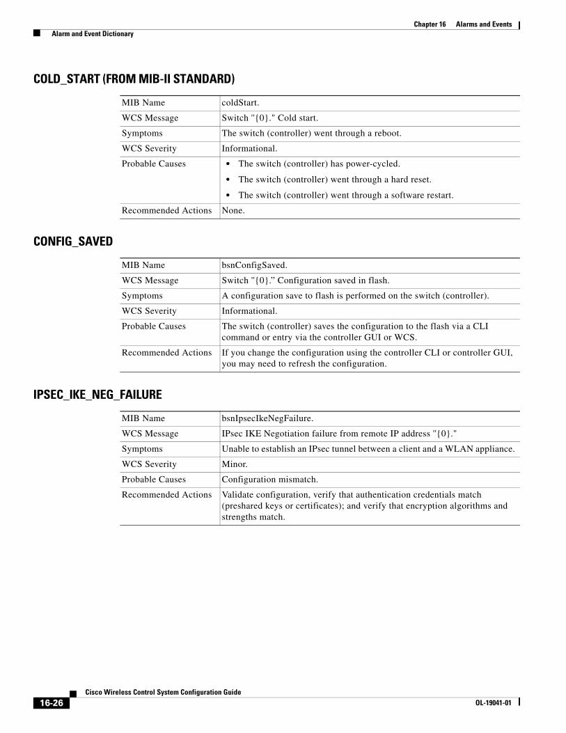
COLD_START (FROM MIB-II STANDARD)
CONFIG_SAVED
IPSEC_IKE_NEG_FAILURE
MIB Name coldStart.
WCS Message Switch ''{0}." Cold start.
Symptoms The switch (controller) went through a reboot.
WCS Severity Informational.
Probable Causes • The switch (controller) has power-cycled.
• The switch (controller) went through a hard reset.
• The switch (controller) went through a software restart.
Recommended Actions None.
MIB Name bsnConfigSaved.
WCS Message Switch ''{0}.” Configuration saved in flash.
Symptoms A configuration save to flash is performed on the switch (controller).
WCS Severity Informational.
Probable Causes The switch (controller) saves the configuration to the flash via a CLI command or entry via the controller GUI or WCS.
Recommended Actions If you change the configuration using the controller CLI or controller GUI, you may need to refresh the configuration.
MIB Name bsnIpsecIkeNegFailure.
WCS Message IPsec IKE Negotiation failure from remote IP address ''{0}."
Symptoms Unable to establish an IPsec tunnel between a client and a WLAN appliance.
WCS Severity Minor.
Probable Causes Configuration mismatch.
Recommended Actions Validate configuration, verify that authentication credentials match (preshared keys or certificates); and verify that encryption algorithms and strengths match.
16-26Cisco Wireless Control System Configuration Guide
OL-19041-01
Chapter 16 Alarms and Events Alarm and Event Dictionary
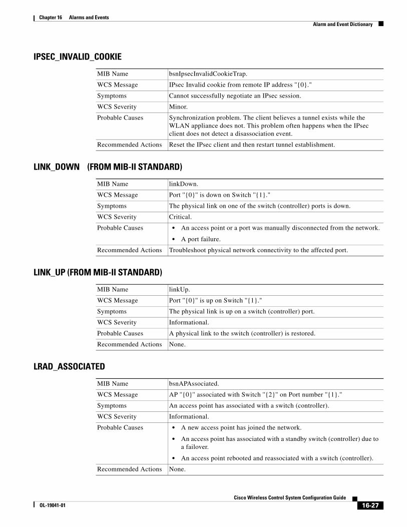
IPSEC_INVALID_COOKIE
LINK_DOWN (FROM MIB-II STANDARD)
LINK_UP (FROM MIB-II STANDARD)
LRAD_ASSOCIATED
MIB Name bsnIpsecInvalidCookieTrap.
WCS Message IPsec Invalid cookie from remote IP address ''{0}."
Symptoms Cannot successfully negotiate an IPsec session.
WCS Severity Minor.
Probable Causes Synchronization problem. The client believes a tunnel exists while the WLAN appliance does not. This problem often happens when the IPsec client does not detect a disassociation event.
Recommended Actions Reset the IPsec client and then restart tunnel establishment.
MIB Name linkDown.
WCS Message Port ''{0}'' is down on Switch ''{1}."
Symptoms The physical link on one of the switch (controller) ports is down.
WCS Severity Critical.
Probable Causes • An access point or a port was manually disconnected from the network.
• A port failure.
Recommended Actions Troubleshoot physical network connectivity to the affected port.
MIB Name linkUp.
WCS Message Port ''{0}'' is up on Switch ''{1}."
Symptoms The physical link is up on a switch (controller) port.
WCS Severity Informational.
Probable Causes A physical link to the switch (controller) is restored.
Recommended Actions None.
MIB Name bsnAPAssociated.
WCS Message AP ''{0}'' associated with Switch ''{2}'' on Port number ''{1}.''
Symptoms An access point has associated with a switch (controller).
WCS Severity Informational.
Probable Causes • A new access point has joined the network.
• An access point has associated with a standby switch (controller) due to a failover.
• An access point rebooted and reassociated with a switch (controller).
Recommended Actions None.
16-27Cisco Wireless Control System Configuration Guide
OL-19041-01
Chapter 16 Alarms and Events Alarm and Event Dictionary
LRAD_DISASSOCIATED
LRADIF_COVERAGE_PROFILE_FAILED
LRADIF_COVERAGE_PROFILE_PASSED
MIB Name bsnAPDisassociated.
WCS Message AP ''{0}'' disassociated from Switch ''{1}.''
Symptoms The switch (controller) is no longer detecting an access point.
WCS Severity Informational.
Probable Causes • A failure in the access point.
• An access point is no longer on the network.
Recommended Actions Check if the access point is powered up and has network connectivity to the switch (controller).
MIB Name bsnAPCoverageProfileFailed.
WCS Message AP ''{0},'' interface ''{1}." Coverage threshold of ''{3}'' is violated. Total no. of clients is ''{5}'' and no. failed clients is ''{4}.''
Symptoms Number of clients experiencing suboptimal performance has crossed the configured threshold.
WCS Severity Minor.
Probable Causes Many clients are wandering to the remote parts of the coverage area of this radio interface with no handoff alternative.
Recommended Actions • If the configured threshold is too low, you may need to readjust it to a more optimal value.
• If the coverage profile occurs on a more frequent basis, you may need to provide additional radio coverage.
• If the power level of this radio can be manually controlled, you may need to boost it to increase the coverage area.
MIB Name bsnAPCoverageProfileUpdatedToPass.
WCS Message AP ''{0},” interface ''{1}." Coverage changed to acceptable.
Symptoms A radio interface that was reporting coverage profile failure has reverted to an acceptable level.
WCS Severity Informational.
Probable Causes The number of clients on this radio interface with suboptimal performance has dropped below the configured threshold.
Recommended Actions None.
16-28Cisco Wireless Control System Configuration Guide
OL-19041-01
Chapter 16 Alarms and Events Alarm and Event Dictionary
LRADIF_CURRENT_CHANNEL_CHANGED
LRADIF_CURRENT_TXPOWER_CHANGED
LRADIF_DOWN
MIB Name bsnAPCurrentChannelChanged.
WCS Message AP ''{0},” interface ''{1}." Channel changed to ''{2}." Interference Energy before update was ''{3}'' and after update is ''{4}.''
Symptoms The current channel assigned to a radio interface has automatically changed.
WCS Severity Informational.
Probable Causes Possible interference on a channel has caused the radio management software on the controller to change the channel.
Recommended Actions None.
MIB Name bsnAPCurrentTxPowerChanged.
WCS Message AP ''{0},” interface ''{1}." Transmit Power Level changed to ''{2}.''
Symptoms The power level has automatically changed on a radio interface.
WCS Severity Informational.
Probable Causes The radio management software on the controller has modified the power level for optimal performance.
Recommended Actions None.
MIB Name bsnAPIfDown.
WCS Message AP ''{0},” interface ''{1}'' is down.
Symptoms A radio interface is out of service.
WCS Severity Critical if not disabled, otherwise Informational.
Probable Causes • A radio interface has failed.
• An administrator has disabled a radio interface.
• An access point has failed and is no longer detected by the controller.
Recommended Actions If the access point is not administratively disabled, call customer support.
16-29Cisco Wireless Control System Configuration Guide
OL-19041-01
Chapter 16 Alarms and Events Alarm and Event Dictionary
LRADF_INTERFERENCE_PROFILE_FAILED
LRADIF_INTERFERENCE_PROFILE_PASSED
MIB Name bsnAPInterferenceProfileFailed.
WCS Message AP ''{0},” interface ''{1}.” Interference threshold violated.
Symptoms The interference detected on one or more channels is violated.
WCS Severity Minor.
Probable Causes There are other 802.11 devices in the same band that are causing interference on channels used by this system.
Recommended Actions • If the interference threshold is configured to be too low, you may need to readjust it to a more optimum value.
• Investigate interference sources such as other 802.11 devices in the vicinity of this radio interface.
A possible workaround is adding one or more access points to distribute the current load or slightly increasing the threshold of the access point which is displaying this message. To perform this workaround, follow the steps below:
1. Choose Configure > Controllers.
2. Click on any IP address in that column of the All Controllers page.
3. From the left sidebar menu, choose 802.11a/n or 802.11b/g/n and then RRM Thresholds.
4. Adjust the Interference Threshold (%) in the Other Thresholds section.
MIB Name bsnAPInterferenceProfileUpdatedToPass.
WCS Message AP ''{0},” interface ''{1}." Interference changed to acceptable.
Symptoms A radio interface reporting interference profile failure has reverted to an acceptable level.
WCS Severity Informational.
Probable Causes The interference on this radio interface has dropped below the configured threshold.
Recommended Actions None.
16-30Cisco Wireless Control System Configuration Guide
OL-19041-01
Chapter 16 Alarms and Events Alarm and Event Dictionary
LRADIF_LOAD_PROFILE_FAILED
LRADIF_LOAD_PROFILE_PASSED
LRADIF_NOISE_PROFILE_FAILED
MIB Name bsnAPLoadProfileFailed.
WCS Message AP ''{0},” interface ''{1}." Load threshold violated.
Symptoms A radio interface of an access point is reporting that the client load has crossed a configured threshold.
WCS Severity Minor.
Probable Causes There are too many clients associated with this radio interface.
Recommended Actions • Verify the client count on this radio interface. If the threshold for this trap is too low, you may need to readjust it.
• Add new capacity to the physical location if the client count is a frequent issue on this radio.
MIB Name bsnAPLoadProfileUpdatedToPass.
WCS Message AP ''{0},'' interface ''{1}." Load changed to acceptable.
Symptoms A radio interface that was reporting load profile failure has reverted to an acceptable level.
WCS Severity Informational.
Probable Causes The load on this radio interface has dropped below the configured threshold.
Recommended Actions None.
MIB Name bsnAPNoiseProfileFailed.
WCS Message AP ''{0},'' interface ''{1}.'' Noise threshold violated.
Symptoms The monitored noise level on this radio has crossed the configured threshold.
WCS Severity Minor.
Probable Causes Noise sources that adversely affect the frequencies on which the radio interface operates.
Recommended Actions • If the noise threshold is too low, you may need to readjust it to a more optimal value.
• Investigate noise sources in the vicinity of the radio interface (for example, a microwave oven).
16-31Cisco Wireless Control System Configuration Guide
OL-19041-01
Chapter 16 Alarms and Events Alarm and Event Dictionary
LRADIF_NOISE_PROFILE_PASSED
LRADIF_UP
MAX_ROGUE_COUNT_CLEAR
MIB Name bsnAPNoiseProfileUpdatedToPass.
WCS Message AP ''{0},'' interface ''{1}." Noise changed to acceptable.
Symptoms A radio interface that was reporting noise profile failure has reverted to an acceptable level.
WCS Severity Informational.
Probable Causes The noise on this radio interface has dropped below the configured threshold.
Recommended Actions None.
MIB Name bsnAPIfUp.
WCS Message AP ''{0},'' interface ''{1}'' is up.
Symptoms A radio interface is back up.
WCS Severity Informational.
Probable Causes • An administrator has enabled a radio interface.
• An access point has turned on.
• A new access point has joined the network.
Recommended Actions None.
MIB Name bsnMaxRogueCountClear.
WCS Message Fake AP or other attack is cleared now. Rogue AP count on system ''{0}'' is within the threshold of ''{1}.''
Symptoms The number of rogues detected by a controller is within acceptable limits.
WCS Severity Informational.
Probable Causes N/A.
Recommended Actions None.
16-32Cisco Wireless Control System Configuration Guide
OL-19041-01
Chapter 16 Alarms and Events Alarm and Event Dictionary
MAX_ROGUE_COUNT_EXCEEDED
MULTIPLE_USERS
NETWORK_DISABLED
NO_ACTIVITY_FOR_ROGUE_AP
MIB Name bsnMaxRogueCountExceeded.
WCS Message Fake AP or other attack may be in progress. Rogue AP count on system ''{0}'' has exceeded the severity warning threshold of ''{1}.''
Symptoms The number of rogues detected by a controller exceeds the internal threshold.
WCS Severity Critical.
Probable Causes • There are too many rogue access points in the network.
• A fake access point attack is in progress.
Recommended Actions Identify the source of the rogue access points.
MIB Name multipleUsersTrap.
WCS Message Switch ''{0}.'' Multiple users logged in.
Symptoms Multiple users with the same login ID are logged in through the CLI.
WCS Severity Informational.
Probable Causes The same user has logged in multiple times through the CLI interface.
Recommended Actions Verify that the expected login sessions for the same user are valid.
MIB Name bsnNetworkStateChanged (bsnNetworkState set to disabled).
WCS Message Global ''{1}'' network status disabled on Switch with IP Address ''{0}."
Symptoms An administrator has disabled the global network for 802.11a/n and 802.11b/g/n.
WCS Severity Informational.
Probable Causes Administrative command.
Recommended Actions None.
MIB Name This is a WCS-only event generated when no rogue activity is seen for a specific duration.
WCS Message Rogue AP ''{0}'' is cleared explicitly. It is not detected anymore.
Symptoms A rogue access point is cleared from the management system due to inactivity.
WCS Severity Informational.
Probable Causes A rogue access point is not located on any managed controller for a specified duration.
Recommended Actions None.
16-33Cisco Wireless Control System Configuration Guide
OL-19041-01
Chapter 16 Alarms and Events Alarm and Event Dictionary
POE_CONTROLLER_FAILURE
RADIOS_EXCEEDED
RADIUS_SERVERS_FAILED
MIB Name bsnPOEControllerFailure.
WCS Message The POE controller has failed on the Switch ''{0}.''
SYMPTOMS A failure in the Power Over Ethernet (POE) unit is detected.
WCS Severity Critical.
Probable Causes The power of the Ethernet unit has failed.
Recommended Actions Call customer support. The unit may need to be repaired.
MIB Name bsnRadiosExceedLicenseCount.
WCS Message The Radios associated with Switch ''{0}'' exceeded license count ''{1}.” The current number of radios on this switch is ''{2}.”
Symptoms The number of supported radios for a switch (controller) has exceeded the licensing limit.
WCS Severity Major.
Probable Causes The number of access points associated with the switch (controller) has exceeded the licensing limits.
Recommended Actions Upgrade the license for the switch (controller) to support a higher number of access points.
MIB Name bsnRADIUSServerNotResponding.
WCS Message Switch ''{0}.” RADIUS server(s) are not responding to authentication requests.
Symptoms The switch (controller) is unable to reach any RADIUS server for authentication.
WCS Severity Critical.
Probable Causes Network connectivity to the RADIUS server is lost or the RADIUS server is down.
Recommended Actions Verify the status of all configured RADIUS servers and their network connectivity.
16-34Cisco Wireless Control System Configuration Guide
OL-19041-01
Chapter 16 Alarms and Events Alarm and Event Dictionary
ROGUE_AP_DETECTED
ROGUE_AP_ON_NETWORK
MIB Name bsnRogueAPDetected.
WCS Message Rogue AP or ad hoc rogue ''{0}'' with SSID ''{3}'' and channel number ''{4}'' is detected by AP ''{1}'' Radio type ''{2}'' with RSSI ''{5}'' and SNR ''{6}.”
Symptoms The system has detected a rogue access point.
WCS Severity Minor if not on a wired network; Critical if on a wired network.
Probable Causes • An illegal access point is connected to the network.
• A known internal or external access point unknown to this system is detected as rogue.
Recommended Actions • Verify the nature of the rogue access point by tracing it using its MAC address or the SSID, or by using location features to locate it physically.
• If the access point is a known internal or external access point, acknowledge it or mark it as a known access point. Consider adding it to the known access point template within WCS.
• If the access point is deemed to be a severity threat, contain it using the management interface.
MIB Name bsnRogueAPDetectedOnWiredNetwork
WCS Message Rogue AP or ad hoc rogue ''{0}'' is on the wired network.
Symptoms A rogue access point is found reachable through the wired network.
WCS Severity Critical.
Probable Causes An illegal access point was detected as reachable through the wired network.
Recommended Actions • Determine if this is a known or valid access point in the system. If it is valid, place it in the known access point list.
• Contain the rogue. Prevent anyone from accessing it until the access point has been traced down using location or other features.
16-35Cisco Wireless Control System Configuration Guide
OL-19041-01
Chapter 16 Alarms and Events Alarm and Event Dictionary
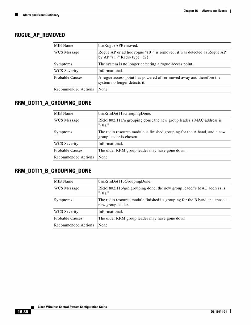
ROGUE_AP_REMOVED
RRM_DOT11_A_GROUPING_DONE
RRM_DOT11_B_GROUPING_DONE
MIB Name bsnRogueAPRemoved.
WCS Message Rogue AP or ad hoc rogue ''{0}'' is removed; it was detected as Rogue AP by AP ''{1}'' Radio type ''{2}.''
Symptoms The system is no longer detecting a rogue access point.
WCS Severity Informational.
Probable Causes A rogue access point has powered off or moved away and therefore the system no longer detects it.
Recommended Actions None.
MIB Name bsnRrmDot11aGroupingDone.
WCS Message RRM 802.11a/n grouping done; the new group leader’s MAC address is ''{0}.''
Symptoms The radio resource module is finished grouping for the A band, and a new group leader is chosen.
WCS Severity Informational.
Probable Causes The older RRM group leader may have gone down.
Recommended Actions None.
MIB Name bsnRrmDot11bGroupingDone.
WCS Message RRM 802.11b/g/n grouping done; the new group leader’s MAC address is ''{0}.''
Symptoms The radio resource module finished its grouping for the B band and chose a new group leader.
WCS Severity Informational.
Probable Causes The older RRM group leader may have gone down.
Recommended Actions None.
16-36Cisco Wireless Control System Configuration Guide
OL-19041-01
Chapter 16 Alarms and Events Alarm and Event Dictionary
SENSED_TEMPERATURE_HIGH
SENSED_TEMPERATURE_LOW
STATION_ASSOCIATE
MIB Name bsnSensedTemperatureTooHigh.
WCS Message The sensed temperature on the Switch ''{0}'' is too high. The current sensed temperature is ''{1}.''
Symptoms The system’s internal temperature has crossed the configured thresholds.
WCS Severity Major.
Probable Causes • Fan failure.
• Fault in the device.
Recommended Actions • Verify the configured thresholds and increase the value if it is too low.
• Call customer support.
MIB Name bsnSensedTemperatureTooLow.
WCS Message The sensed temperature on the Switch ''{0}'' is too low. The current sensed temperature is ''{1}.''
Symptoms The internal temperature of the device is below the configured limit in the system.
WCS Severity Major.
Probable Causes • Operating environment.
• Hardware fault.
Recommended Actions • Verify the configured thresholds and ensure that the limit is appropriate.
• Call customer support.
MIB Name bsnDot11StationAssociate.
WCS Message Client ''{0}'' is associated with AP ''{1},'' interface ''{2}.''
Symptoms A client has associated with an access point.
WCS Severity Informational.
Probable Causes A client has associated with an access point.
Recommended Actions None.
16-37Cisco Wireless Control System Configuration Guide
OL-19041-01
Chapter 16 Alarms and Events Alarm and Event Dictionary
STATION_ASSOCIATE_FAIL
STATION_AUTHENTICATE
STATION_AUTHENTICATION_FAIL
MIB Name bsnDot11StationAssociateFail.
WCS Message Client ''{0}'' failed to associate with AP ''{1},'' interface ''{2}.'' The reason code is ''{3}.''
Symptoms A client station failed to associate with the system.
WCS Severity Informational.
Probable Causes The access point was busy.
Recommended Actions Check whether the access point is busy and reporting load profile failures.
MIB Name bsnDot11StationAssociate (bsnStationUserName is set).
WCS Message Client ''{0}'' with user name ''{3}'' is authenticated with AP ''{1},'' interface ''{2}.''
Symptoms A client has successfully authenticated with the system.
WCS Severity Informational.
Probable Causes A client has successfully authenticated with the system.
Recommended Actions None.
MIB Name bsnDot11StationAuthenticateFail.
WCS Message Client ''{0}'' has failed authenticating with AP ''{1},'' interface ''{2}.'' The reason code is ''{3}.''
Symptoms The system failed to authenticate a client.
WCS Severity Informational.
Probable Causes Failed client authentication.
Recommended Actions Check client configuration and configured keys or passwords in the system.
16-38Cisco Wireless Control System Configuration Guide
OL-19041-01
Chapter 16 Alarms and Events Alarm and Event Dictionary
STATION_BLACKLISTED
STATION_DEAUTHENTICATE
STATION_DISASSOCIATE
MIB Name bsnDot11StationBlacklisted.
WCS Message Client ''{0}'' which was associated with AP ''{1},'' interface ''{2}'' is excluded. The reason code is ''{3}.''
Symptoms A client is in the exclusion list and is not allowed to authenticate for a configured interval.
WCS Severity Minor.
Probable Causes • Repeated authentication or association failures from the client station.
• A client is attempting to use an IP address assigned to another device.
Recommended Actions • Verify the configuration or the client along with its credentials.
• Remove the client from the exclusion list by using the management interface if the client needs to be allowed back into the network.
MIB Name bsnDot11StationDeauthenticate.
WCS Message Client ''{0}'' is deauthenticated from AP ''{1},'' interface ''{2}'' with reason code ''{3}.''
Symptoms A client is no longer authenticated by the system.
WCS Severity Informational.
Probable Causes A client is no longer authenticated by the system.
Recommended Actions None.
MIB Name bsnDot11StationDisassociate.
WCS Message Client ''{0}'' is disassociated from AP ''{1},'' interface ''{2}'' with reason code ''{3}.''
Symptoms A client has disassociated with an access point in the system.
WCS Severity Informational.
Probable Causes A station may disassociate due to various reasons such as inactivity timeout or a forced action from the management interface.
Recommended Actions None.
16-39Cisco Wireless Control System Configuration Guide
OL-19041-01
Chapter 16 Alarms and Events Alarm and Event Dictionary
STATION_WEP_KEY_DECRYPT_ERROR
STATION_WPA_MIC_ERROR_COUNTER_ACTIVATED
SWITCH_DETECTED_DUPLICATE_IP
MIB Name bsnWepKeyDecryptError.
WCS Message The WEP Key configured at the station may be wrong. Station MAC Address is ''{0},'' AP MAC is ''{1}'' and Slot ID is ''{2}.''
Symptoms A client station seems to have the wrong WEP key.
WCS Severity Minor.
Probable Causes A client has an incorrectly configured WEP key.
Recommended Actions Identify the client and correct the WEP key configuration.
MIB Name bsnWpaMicErrorCounterActivated.
WCS Message The AP ''{1}'' received a WPA MIC error on protocol ''{2}'' from Station ''{0}." Counter measures have been activated and traffic has been suspended for 60 seconds.
Symptoms A client station has detected a WPA MIC error.
WCS Severity Critical.
Probable Causes A possible hacking attempt is underway.
Recommended Actions Identify the station that is the source of this threat.
MIB Name bsnDuplicateIpAddressReported.
WCS Message Switch ''{0}'' detected duplicate IP address ''{0}'' being used by machine with mac address ''{1}.''
Symptoms The system has detected a duplicate IP address in the network that is assigned to the switch (controller).
WCS Severity Critical.
Probable Causes Another device in the network is configured with the same IP address as that of the switch (controller).
Recommended Actions Correct the misconfiguration of IP addresses in the network.
16-40Cisco Wireless Control System Configuration Guide
OL-19041-01
Chapter 16 Alarms and Events Alarm and Event Dictionary
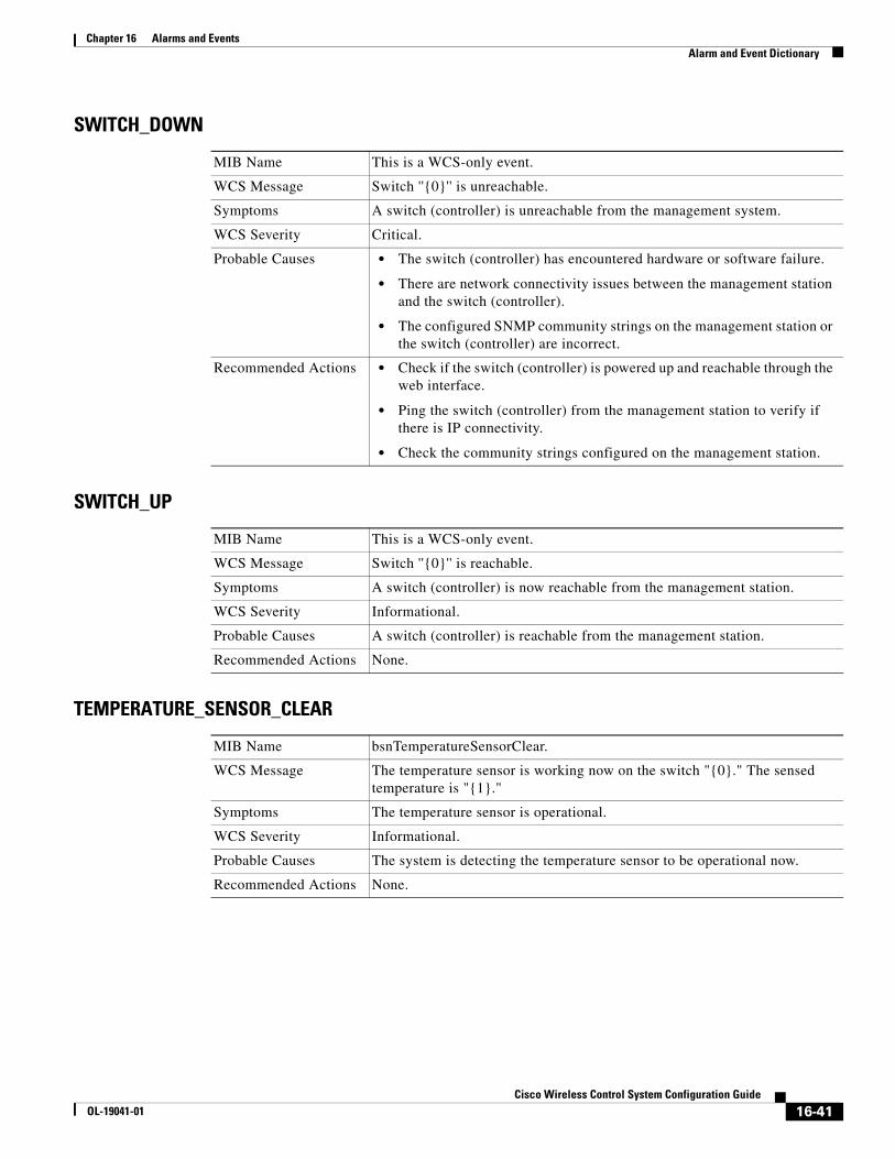
SWITCH_DOWN
SWITCH_UP
TEMPERATURE_SENSOR_CLEAR
MIB Name This is a WCS-only event.
WCS Message Switch ''{0}'' is unreachable.
Symptoms A switch (controller) is unreachable from the management system.
WCS Severity Critical.
Probable Causes • The switch (controller) has encountered hardware or software failure.
• There are network connectivity issues between the management station and the switch (controller).
• The configured SNMP community strings on the management station or the switch (controller) are incorrect.
Recommended Actions • Check if the switch (controller) is powered up and reachable through the web interface.
• Ping the switch (controller) from the management station to verify if there is IP connectivity.
• Check the community strings configured on the management station.
MIB Name This is a WCS-only event.
WCS Message Switch ''{0}'' is reachable.
Symptoms A switch (controller) is now reachable from the management station.
WCS Severity Informational.
Probable Causes A switch (controller) is reachable from the management station.
Recommended Actions None.
MIB Name bsnTemperatureSensorClear.
WCS Message The temperature sensor is working now on the switch "{0}." The sensed temperature is "{1}."
Symptoms The temperature sensor is operational.
WCS Severity Informational.
Probable Causes The system is detecting the temperature sensor to be operational now.
Recommended Actions None.
16-41Cisco Wireless Control System Configuration Guide
OL-19041-01
Chapter 16 Alarms and Events Alarm and Event Dictionary
TEMPERATURE_SENSOR_FAILURE
TOO_MANY_USER_UNSUCCESSFUL_LOGINS
Traps Added in Release 2.1
ADHOC_ROGUE_AUTO_CONTAINED
MIB Name bsnTemperatureSensorFailure.
WCS Message The temperature sensor failed on the Switch ''{0}.'' Temperature is unknown.
Symptoms The system is reporting that a temperature sensor has failed and the system is unable to report accurate temperature.
WCS Severity Major.
Probable Causes The temperature sensor has failed due to hardware failure.
Recommended Actions Call customer support.
MIB Name bsnTooManyUnsuccessLoginAttempts.
WCS Message User ''{1}'' with IP Address ''{0}'' has made too many unsuccessful login attempts.
Symptoms A management user has made too many login attempts.
WCS Severity Critical.
Probable Causes • An admin user has made too many login attempts.
• A user attempted to break into the administration account of the management system.
Recommended Actions • Identify the source of the login attempts and take the appropriate action.
• Increase the value of the login attempt threshold if it is too low.
MIB Name bsnAdhocRogueAutoContained.
WCS Message Adhoc Rogue ''{0}'' was found and is auto contained as per WPS policy.
Symptoms The system detected an ad hoc rogue and automatically contained it.
WCS Severity Major.
Probable Causes The system detected an ad hoc rogue and automatically contained it as configured in the system’s wireless prevention policy.
Recommended Actions Identify the ad hoc rogue through the location application and take the appropriate action.
16-42Cisco Wireless Control System Configuration Guide
OL-19041-01
Chapter 16 Alarms and Events Alarm and Event Dictionary
ADHOC_ROGUE_AUTO_CONTAINED_CLEAR
NETWORK_ENABLED
ROGUE_AP_AUTO_CONTAINED
ROGUE_AP_AUTO_CONTAINED_CLEAR
MIB Name bsnAdhocRogueAutoContained (bsnClearTrapVariable set to true).
WCS Message Adhoc Rogue ''{0}'' was found and was auto contained. The alert state is clear now.
Symptoms An ad hoc rogue that the system has detected earlier is now clear.
WCS Severity Informational.
Probable Causes The system no longer detects an ad hoc rogue.
Recommended Actions None.
MIB Name bsnNetworkStateChanged (bsnNetworkState set to enabled).
WCS Message Global ''{1}'' network status enabled on Switch with IP Address ''{0}."
Symptoms An administrator has enabled the global network for 802.11a/n or 802.11b/g/n.
WCS Severity Informational.
Probable Causes Administrative command.
Recommended Actions None.
MIB Name bsnRogueApAutoContained.
WCS Message Rogue AP ''{0}'' is advertising our SSID and is auto contained as per WPS policy.
Symptoms The system has automatically contained a rogue access point.
WCS Severity Major.
Probable Causes The system detected an ad hoc rogue and automatically contained it as configured in the system’s wireless prevention policy.
Recommended Actions • Track the location of the rogue and take the appropriate action.
• If this is a known valid access point, clear the rogue from containment.
MIB Name bsnRogueApAutoContained (bsnClearTrapVariable set to true).
Message Rogue AP ''{0}'' was advertising our SSID and was auto contained. The alert state is clear now.
Symptoms The system has cleared a previously contained rogue.
WCS Severity Informational.
Probable Causes The system has cleared a previously contained rogue.
Recommended Actions None.
16-43Cisco Wireless Control System Configuration Guide
OL-19041-01
Chapter 16 Alarms and Events Alarm and Event Dictionary
TRUSTED_AP_INVALID_ENCRYPTION
TRUSTED_AP_INVALID_ENCRYPTION_CLEAR
TRUSTED_AP_INVALID_RADIO_POLICY
TRUSTED_AP_INVALID_RADIO_POLICY_CLEAR
MIB Name bsnTrustedApHasInvalidEncryption.
WCS Message Trusted AP ''{0}'' is invalid encryption. It is using ''{1}'' instead of ''{2}." It is auto contained as per WPS policy.
Symptoms The system automatically contained a trusted access point that has invalid encryption.
WCS Severity Major.
Probable Causes The system automatically contained a trusted access point that violated the configured encryption policy.
Recommended Actions Identify the trusted access point and take the appropriate action.
MIB Name bsnTrustedApHasInvalidEncryption (bsnClearTrapVariable set to true).
WCS Message Trusted AP ''{0}'' had invalid encryption. The alert state is clear now.
Symptoms The system has cleared a previous alert about a trusted access point.
WCS Severity Informational.
Probable Causes The trusted access point has now conformed to the configured encryption policy.
Recommended Actions None.
MIB Name bsnTrustedApHasInvalidRadioPolicy.
WCS Message Trusted AP ''{0}'' has invalid radio policy. It is using ''{1}'' instead of ''{2}." It has been auto contained as per WPS policy.
Symptoms The system has contained a trusted access point with an invalid radio policy.
WCS Severity Major.
Probable Causes The system has contained a trusted access point connected to the wireless system for violating the configured radio policy.
Recommended Actions Identify the trusted access point and take the appropriate action.
MIB Name bsnTrustedApHasInvalidRadioPolicy (bsnClearTrapVariable set to true).
WCS Message Trusted AP ''{0}'' had invalid radio policy. The alert state is clear now.
Symptoms The system has cleared a previous alert about a trusted access point.
WCS Severity Informational.
Probable Causes The trusted access point has now conformed to the configured encryption policy.
Recommended Actions None.
16-44Cisco Wireless Control System Configuration Guide
OL-19041-01
Chapter 16 Alarms and Events Alarm and Event Dictionary
TRUSTED_AP_INVALID_SSID
TRUSTED_AP_INVALID_SSID_CLEAR
TRUSTED_AP_MISSING
TRUSTED_AP_MISSING_CLEAR
MIB Name bsnTrustedApHasInvalidSsid.
WCS Message Trusted AP ''{0}'' has invalid SSID. It was auto contained as per WPS policy.
Symptoms The system has automatically contained a trusted access point for advertising an invalid SSID.
WCS Severity Major.
Probable Causes The system has automatically contained a trusted access point for violating the configured SSID policy.
Recommended Actions Identify the trusted access point and take the appropriate action.
MIB Name bsnTrustedApHasInvalidSsid (bsnClearTrapVariable set to true).
WCS Message Trusted AP ''{0}'' had invalid SSID. The alert state is clear now.
Symptoms The system has cleared a previous alert about a trusted access point.
WCS Severity Informational.
Probable Causes The trusted access point has now conformed to the configured policy.
Recommended Actions None.
MIB Name bsnTrustedApIsMissing.
WCS Message Trusted AP ''{0}'' is missing or has failed.
Symptoms The wireless system no longer detects a trusted access point.
WCS Severity Major.
Probable Causes A trusted access point has left the network or has failed.
Recommended Actions Track down the trusted access point and take the appropriate action.
MIB Name bsnTrustedApIsMissing (bsnClearTrapVariable set to true).
WCS Message Trusted AP ''{0}'' is missing or has failed. The alert state is clear now.
Symptoms The system has found a trusted access point again.
WCS Severity Informational.
Probable Causes The system has detected a previously missing trusted access point.
Recommended Actions None.
16-45Cisco Wireless Control System Configuration Guide
OL-19041-01
Chapter 16 Alarms and Events Alarm and Event Dictionary
Traps Added in Release 2.2
AP_IMPERSONATION_DETECTED
AP_RADIO_CARD_RX_FAILURE
AP_RADIO_CARD_RX_FAILURE_CLEAR
MIB Name bsnAPImpersonationDetected.
WCS Message AP Impersonation with MAC ''{0}'' is detected by authenticated AP ''{1}'' on ''{2}'' radio and Slot ID ''{3}.''
Symptoms A radio of an authenticated access point has heard from another access point whose MAC address neither matches that of a rogue nor is it an authenticated neighbor of the detecting access point.
WCS Severity Critical.
Probable Causes A severity breach related to access point impersonation may be under way.
Recommended Actions Track down the MAC address of the impersonating access point in the network and contain it.
MIB Name bsnAPRadioCardRxFailure.
WCS Message Receiver failure detected on the ''{0}'' radio of AP ''{1}'' on Switch ''{2}."
Symptoms A radio card is unable to receive data.
WCS Severity Critical.
Probable Causes • A radio card is experiencing reception failure.
• The antenna of the radio is disconnected.
Recommended Actions • Check the access point’s antenna connection.
• Call customer support.
MIB Name bsnAPRadioCardRxFailureClear.
WCS Message Receiver failure cleared on the ''{0}'' radio of AP ''{1}'' on Switch ''{2}."
Symptoms A radio is no longer experiencing reception failure.
WCS Severity Informational.
Probable Causes A malfunction in the access point has been corrected.
Recommended Actions None.
16-46Cisco Wireless Control System Configuration Guide
OL-19041-01
Chapter 16 Alarms and Events Alarm and Event Dictionary
AP_RADIO_CARD_TX_FAILURE
AP_RADIO_CARD_TX_FAILURE_CLEAR
SIGNATURE_ATTACK_CLEARED
MIB Name bsnAPRadioCardTxFailure.
WCS Message Transmitter failure detected on the ''{0}'' radio of AP ''{1}'' on Switch ''{2}."
Symptoms A radio card is unable to transmit.
WCS Severity Critical.
Probable Causes • A radio card is experiencing transmission failure.
• The antenna of the radio may be disconnected.
Recommended Actions • Check the antenna of the access point.
• Call customer support.
MIB Name bsnAPRadioCardTxFailureClear.
WCS Message Transmitter failure cleared on the ''{0}'' radio of AP ''{1}'' on Switch ''{2}."
Symptoms A radio is no longer experiencing transmission failure.
WCS Severity Informational.
Probable Causes A malfunction in the access point has been corrected.
Recommended Actions None.
MIB Name bsnSignatureAttackDetected (bsnClearTrapVariable is set to True).
WCS Message Switch ''{0}'' is cleared from IDS signature attack. The wireless system is no longer detecting the intrusion.
Symptoms The switch (controller) no longer detects a signature attack.
WCS Severity Informational.
Probable Causes The signature attack that the system previously detected has stopped.
Recommended Actions None.
16-47Cisco Wireless Control System Configuration Guide
OL-19041-01
Chapter 16 Alarms and Events Alarm and Event Dictionary
SIGNATURE_ATTACK_DETECTED
TRUSTED_AP_HAS_INVALID_PREAMBLE
TRUSTED_HAS_INVALID_PREAMBLE_CLEARED
MIB Name bsnSignatureAttackDetected
WCS Message IDS Signature attack detected on Switch ''{0}." The Signature Type is ''{1}," Signature Name is ''{2},'' and Signature description is ''{3}."
Symptoms The switch (controller) is detecting a signature attack. The switch (controller) has a list of signatures that it monitors. When it detects a signature, it provides the name of the signature attack in the alert it generates.
WCS Severity Critical.
Probable Causes Someone is mounting a malevolent signature attack.
Recommended Actions Track down the source of the signature attack in the wireless network and take the appropriate action.
MIB Name bsnTrustedApHasInvalidPreamble.
WCS Message Trusted AP ''{0}'' on Switch ''{3}'' has invalid preamble. It is using ''{1}'' instead of ''{2}." It has been auto contained as per WPS policy.
Symptoms The system has contained a trusted rogue access point for using an invalid preamble.
WCS Severity Major.
Probable Causes The system has detected a possible severity breach because a rogue is transmitting an invalid preamble.
Recommended Actions Locate the rogue access point using location features or the access point detecting it and take the appropriate actions.
MIB Name bsnTrustedApHasInvalidPreamble (bsnClearTrapVariable is set to true).
WCS Message Trusted AP ''{0}'' on Switch ''{3}'' had invalid preamble. The alert state is clear now.
Symptoms The system has cleared a previous alert about a trusted access point.
WCS Severity Informational.
Probable Causes The system has cleared a previous alert about a trusted access point.
Recommended Actions None.
16-48Cisco Wireless Control System Configuration Guide
OL-19041-01
Chapter 16 Alarms and Events Alarm and Event Dictionary
Traps Added in Release 3.0
AP_FUNCTIONALITY_DISABLED
AP_IP_ADDRESS_FALLBACK
MIB Name bsnAPFunctionalityDisabled.
WCS Message AP functionality has been disabled for key ''{0}," reason being ''{1}'' for feature-set ''{2}."
Symptoms The system sends this trap out when the controller disables access point functionality because the license key has expired.
WCS Severity Critical.
Probable Causes When the controller boots up, it checks whether the feature license key matches the controller’s software image. If it does not, the controller disables access point functionality.
Recommended Actions Configure the correct license key on the controller and reboot it to restore access point functionality.
MIB Name bsnAPIPAddressFallback.
WCS Message AP ''{0}'' with static-ip configured as ''{2}'' has fallen back to the working DHCP address ''{1}."
Symptoms This trap is sent out when an access point, with the configured static ip-address, fails to establish connection with the outside world and starts using DHCP as a fallback option.
WCS Severity Minor.
Probable Causes If the configured IP address on the access point is incorrect or obsolete, and if the AP Fallback option is enabled on the switch (controller), the access point starts using DHCP.
Recommended Actions Reconfigure the access point’s static IP to the correct IP address if desired.
16-49Cisco Wireless Control System Configuration Guide
OL-19041-01
Chapter 16 Alarms and Events Alarm and Event Dictionary
AP_REGULATORY_DOMAIN_MISMATCH
RX_MULTICAST_QUEUE_FULL
MIB Name bsnAPRegulatoryDomainMismatch.
WCS Message AP ''{1}'' is unable to associate. The Regulatory Domain configured on it ''{3}'' does not match the Controller ''{0}'' country code ''{2}."
Symptoms The system generates this trap when an access point’s regulatory domain does not match the country code configured on the controller. Due to the country code mismatch, the access point will fail to associate with the controller.
WCS Severity Critical.
Probable Causes • If someone changes the controller’s country code configuration and some of the existing access points support a different country code, these access points fail to associate.
• An access point on the controller’s network sends join requests to the controller, but the regulatory domain is outside the domain in which the controller is operating.
Recommended Actions Either remove the access points that are not meant for inclusion in the controller’s domain or correct the controller’s country code setting.
MIB Name bsnRxMulticastQueueFull.
WCS Message CPU Receive Multicast Queue is full on Controller ''{0}."
Symptoms This trap indicates that the CPU’s Receive Multicast queue is full.
WCS Severity Critical.
Probable Causes An ARP storm.
Recommended Actions None.
16-50Cisco Wireless Control System Configuration Guide
OL-19041-01
Chapter 16 Alarms and Events Alarm and Event Dictionary
Traps Added in Release 3.1
AP_AUTHORIZATION_FAILURE
HEARTBEAT_LOSS_TRAP
MIB Name bsnAPAuthorizationFailure
WCS Message • Failed to authorize AP “{0}." Authorization entry does not exist in Controllers “{1}” AP Authorization List.
• Failed to authorize AP “{0}." AP’s authorization key does not match with SHA1 key in Controllers “{1}” AP Authorization List.
• Failed to authorize AP “{0}." Controller “{1}” could not verify the Self Signed Certificate from the AP.
• Failed to authorize AP “{0}." AP has a self signed certificate where as the Controllers “{1}” AP authorization list has Manufactured Installed Certificate for this AP.
Symptoms An alert is generated when an access point fails to associate with a controller due to authorization issues.
WCS Severity Critical.
Probable Causes • The access point is not on the controller's access point authorization list.
• The key entry in the controller's access point authorization list does not match the SHA1 key received from the access point.
• The access point self-signed certificate is not valid.
• The access point has a self-signed certificate and the controller’s access point authorization list (for the given access point) references a manufactured installed certificate.
Recommended Actions • Add the access point to the controller’s authorization list.
• Update the access point’s authorization key to match the controller’s access point key.
• Check the accuracy of the access point’s self-signed certificate.
• Check the certificate type of the access point in the controller’s access point authorization list.
MIB Name heartbeatLossTrap.
WCS Message Keepalive messages are lost between Master and Controller''{0}.”
Symptoms This trap is generated when the controller loses connection with the Supervisor Switch (in which it is physically embedded) and the controller cannot hear the heartbeat (keepalives) from the Supervisor.
WCS Severity Major.
Probable Causes • Port on the WiSM controller could be down.
• Loss of connection with the Supervisor Switch.
Recommended Actions None.
16-51Cisco Wireless Control System Configuration Guide
OL-19041-01
Chapter 16 Alarms and Events Alarm and Event Dictionary
INVALID_RADIO_INTERFACE
RADAR_CLEARED
RADAR_DETECTED
MIB Name invalidRadioTrap.
WCS Message Radio with MAC address “{0}” and protocol “{1}” that has joined controller “{2}” has invalid interface. The reason is “{3}.”
Symptoms If a Cisco access point joins the network but has unsupported radios, the controller detects this and generates a trap. This symptom propogates an alert in WCS.
WCS Severity Critical.
Probable Causes The radio hardware is not supported by the controller.
Recommended Actions None.
MIB Name bsnRadarChannelCleared
WCS Message Radar has been cleared on channel ''{1}'' which was detected by AP base radio MAC ''{0}'' on radio 802.11a/n.
Symptoms Trap is generated after the expiry of a non-occupancy period for a channel that previously generated a radar trap.
WCS Severity Informational.
Probable Causes Trap is cleared on a channel.
Recommended Actions None.
MIB Name bsnRadarChannelDetected
WCS Message Radar has been detected on channel ''{1}'' by AP base radio MAC ''{0}'' on radio 802.11a/n.
Symptoms This trap is generated when radar is detected on the channel on which an access point is currently operating.
WCS Severity Informational.
Probable Causes Radar is detected on a channel.
Recommended Actions None.
16-52Cisco Wireless Control System Configuration Guide
OL-19041-01
Chapter 16 Alarms and Events Alarm and Event Dictionary
RADIO_CORE_DUMP
RADIO_INTERFACE_DOWN
RADIO_INTERFACE_UP
MIB Name radioCoreDumpTrap
WCS Message Radio with MAC address “{0}” and protocol “{1}” has core dump on controller “{2}."
Symptoms When a Cisco radio fails and a core dump occurs, the controller generates a trap and WCS generates an event for this trap.
WCS Severity Informational.
Probable Causes Radio failure.
Recommended Actions Capture the core dump file using the controller’s command line interface and send to TAC support.
MIB Name bsnAPIfDown.
WCS Message Radio with MAC address “{0}” and protocol “{1}” is down. The reason is “{2}.”
Symptoms When a radio interface is down, WCS generates an alert. Reason for the radio outage is also noted.
WCS Severity Critical if not manually disabled. Informational if radio interface was manually disabled.
Probable Causes • The radio interface has failed.
• The access point cannot draw enough power.
• The maximum number of transmissions for the access point is reached.
• The access point has lost connection with the controller heart beat.
• The admin status of the access point admin is disabled.
• The admin status of the radio is disabled.
Recommended Actions None.
MIB Name bsnAPIfUp.
WCS Message Radio with MAC address “{0}” and protocol “{1}” is up. The reason is “{2}.”
Symptoms When a radio interface is operational again, WCS clears the previous alert. Reason for the radio being up again is also noted.
WCS Severity Informational.
Probable Causes • Admin status of access point is enabled.
• Admin status of radio is enabled.
• Global network admin status is enabled.
Recommended Actions None.
16-53Cisco Wireless Control System Configuration Guide
OL-19041-01
Chapter 16 Alarms and Events Alarm and Event Dictionary
UNSUPPORTED_AP
Traps Added in Release 3.2
LOCATION_NOTIFY_TRAP
MIB Name unsupportedAPTrap.
WCS Message AP “{0}” tried to join controller “{1}” and failed. The controller does not support this kind of AP.
Symptoms When unsupported access points try to join 40xx/410x controllers or 3500 controller with 64 MB flash, these controllers generate a trap, and the trap is propagated as an event in WCS.
WCS Severity Informational.
Probable Causes Access point is not supported by the controller.
Recommended Actions None.
MIB Name locationNotifyTrap.
WCS Message Depending on the notification condition reported, the trap is sent out in an XML format and is reflected in WCS with the following alert messages:
• Absence of <Element> with MAC <macAddress>, last seen at <timestamp>.
• <Element> with MAC <macAddress> is <In | Out> the Area <campus | building | floor | coverageArea>.
• <Element> with MAC <macAddress> has moved beyond <specifiedDistance> ft. of marker <MarkerName>, located at a range of <foundDistance> ft.
For detailed info on the XML format for the trap content, consult the 2700 Location Appliance Configuration Guide.
Symptoms A 2700 location appliance sends this trap out when the defined location notification conditions are met (such at element outside area, elements missing, and elements exceeded specified distance). WCS uses this trap to display alarms about location notification conditions.
WCS Severity Minor (under the Location Notification dashboard).
Probable Causes The location notification conditions configured for a 2700 location appliance are met for certain elements on the network.
Recommended Actions None.
16-54Cisco Wireless Control System Configuration Guide
OL-19041-01
Chapter 16 Alarms and Events Alarm and Event Dictionary
Traps Added In Release 4.0
CISCO_LWAPP_MESH_POOR_SNR
CISCO_LWAPP_MESH_PARENT_CHANGE
CISCO_LWAPP_MESH_CHILD_MOVED
MIB Name ciscoLwappMeshPoorSNR
WCS Message Poor SNR.
Symptoms SNR (signal-to-noise) ratio is important because high signal strength is not enough to ensure good receiver performance. The incoming signal must be stronger than any noise or interference that is present. For example, you can have high signal strength and still have poor wireless performance if there is strong interference or a high noise level.
WCS Severity Major.
Probable Causes The link SNR fell below 12 db. The threshold level cannot be changed. If poor SNR is detected on the backhaul link for a child or parent, the trap is generated and contains SNR values and MAC addresses.
Recommended Actions None.
MIB Name ciscoLwappMeshParentChange
WCS Message Parent changed.
Symptoms When the parent is lost, the child joins with another parent, and the child sends traps containing both old and new parent’s MAC addresses.
WCS Severity Info.
Probable Causes The child moved to another parent.
Recommended Actions None.
MIB Name ciscoLwappMeshChildMoved
WCS Message Child moved.
Symptoms When the parent access point detects a child being lost and communication is halted, the child lost trap is sent to WCS, along with the child MAC address.
WCS Severity Info.
Probable Causes The child moved from the parent.
Recommended Actions None.
16-55Cisco Wireless Control System Configuration Guide
OL-19041-01
Chapter 16 Alarms and Events Alarm and Event Dictionary
CISCO_LWAPP_MESH_CONSOLE_LOGIN
CISCO_LWAPP_MESH_AUTHORIZATION_FAILURE
MIB Name ciscoLwappMeshConsoleLogin
WCS Message Console login successful or failed.
Symptoms The console port provides the ability for the customer to change the user name and password to recover the stranded outdoor access point. To prevent any unauthorized user access to the access point, WCS sends an alarm when someone tries to log in. This alarm is required to provide protection because the access point is physically vulnerable being located outdoors.
WCS Severity A login is of critical severity.
Probable Causes You have successfully logged in to the access point console port or failed on three consecutive tries.
Recommended Actions None.
MIB Name ciscoLwappMeshAuthorizationFailure
WCS Message Fails to authenticate with controller.
Symptoms WCS receives a trap from the controller. The trap contains the MAC addresses of those access points that failed authorization.
WCS Severity Minor.
Probable Causes The access point tried to join the MESH but failed to authenticate because the MESH node MAC address was not on the MAC filter list.
Recommended Actions None.
16-56Cisco Wireless Control System Configuration Guide
OL-19041-01
Chapter 16 Alarms and Events Alarm and Event Dictionary
CISCO_LWAPP_MESH_CHILD_EXCLUDED_PARENT
CISCO_LWAPP_MESH_EXCESSIVE_PARENT_CHANGE
IDS_SHUN_CLIENT_TRAP
MIB Name ciscoLwappMeshChildExcludedParent
WCS Message Parent AP being excluded by child AP.
Symptoms When a child fails authentication at the controller after a fixed number of attempts, the child can exclude that parent. The child remembers the excluded parent so that when it joins the network, it sends the trap which contains the excluded parent MAC address and the duration of the exclusion period.
WCS Severity Info.
Probable Causes A child marked a parent for exclusion.
Recommended Actions None.
MIB Name ciscoLwappMeshExcessiveParentChange
WCS Message Parent changed frequently.
Symptoms When MAP parent-change-counter exceeds the threshold within a given duration, it sends a trap to WCS. The trap contains the number of times the MAP changes and the duration of the time. The threshold is user configurable.
WCS Severity Major.
Probable Causes The MESH access point changed its parent frequently.
Recommended Actions None.
MIB Name CISCO-LWAPP-IDS-MIB. CLIdsNewShunClient.
WCS Message The Cisco Intrusion Detection System "{0}" has detected a possible intrusion attack by the wireless client "{1}."
Symptoms This trap is generated in response to a shun client clear alert originated from a Cisco IDS/IPs appliance ("{0}") installed in the data path between the wireless client ("{1}") and the site’s intranet.
WCS Severity Critical.
Probable Causes The designated client is generating a packet-traffic pattern which shares properties with a well-known form of attack on the customer’s network.
Recommended Actions Investigate the designated client and determine if it is an intruder, a virus, or a false alarm.
16-57Cisco Wireless Control System Configuration Guide
OL-19041-01
Chapter 16 Alarms and Events Alarm and Event Dictionary
IDS_SHUN_CLIENT_CLEAR_TRAP
MFP_TIMEBASE_STATUS_TRAP
MIB Name CISCO-LWAPP-IDS-MIB. cLIdsNewShunClientClear.
WCS Message The Cisco Intrusion Detection System "{0}" has cleared the wireless client "{1}" from possibly having generated an intrusion attack.
Symptoms This trap is generated is response to one of two things: 1) a shun client clear alert originated from a Cisco IDS/IPS appliance ("{0}") installed in the data path between the wireless client ("{1"}) and the site’s intranet, or 2) a scheduled timeout of the original IDS_SHUN_CLIENT_TRAP for the wireless client.
WCS Severity Clear.
Probable Causes The designated client is no longer generating a suspicious packet-traffic pattern.
Recommended Actions None.
MIB Name CISCO-LWAPP-MFP-MIB. ciscoLwappMfpTimebaseStatus.
WCS Message Controller "{0}" is "{1}" with the Central time server.
Symptoms This notification is sent by the agent to indicate when the synchronization of the controller’s time base with the Central time base last occurred.
WCS Severity Critical (not in sync trap) and clear (sync trap).
Probable Causes The controller’s time base is not in sync with the Central time base.
Recommended Actions None.
16-58Cisco Wireless Control System Configuration Guide
OL-19041-01
Chapter 16 Alarms and Events Alarm and Event Dictionary
MFP_ANOMALY_DETECTED_TRAP
GUEST_USER_REMOVED_TRAP
MIB Name CISCO-LWAPP-MFP-MIB. ciscoLwappMfpAnomalyDetected.
WCS Message MFP configuration of the WLAN was violated by the radio interface "{0}" and detected by the radio interface "{1}" of the access point with MAC address "{2}." The violation is "{3}."
Symptoms This notification is sent by the agent when the MFP configuration of the WLAN was violated by the radio interface cLApIfSmtDot11Bssid and detected by the radio interface cLApDot11IfSlotId of the access point cLApSysMacAddress. This violation is indicated by cLMfpEventType.
When observing the management frame(s) given by cLMfpEventFrames for the last cLMfpEventPeriod time units, the controller reports the occurrence of a total of cLMfpEventTotal violation events of type cLMfpEventType. When the cLMfpEventTotal is 0, no further anomalies have recently been detected, and the NMS should clear any alarm raised about the MFP errors.
Note This notification is generated by the controller only if MFP was configured as the protection mechanism through cLMfpProtectType.
WCS Severity Critical.
Probable Causes The MFP configuration of the WLAN was violated. Various types of violations are invalidMic, invalidSeq, noMic, and unexpectedMic.
Recommended Actions None.
MIB Name CISCO-LWAPP-WEBAUTH-MIB. cLWAGuestUserRemoved.
WCS Message Guest user "{1}" deleted on controller "{0}."
Symptoms This notification is generated when the lifetime of the guest user {1} expires and the guest user’s accounts are removed from the controller "{0}."
WCS Severity Critical.
Probable Causes GuestUserAccountLifetime expired.
Recommended Actions None.
16-59Cisco Wireless Control System Configuration Guide
OL-19041-01
Chapter 16 Alarms and Events Alarm and Event Dictionary
Traps Added or Updated in Release 4.0.96.0
AP_IMPERSONATION_DETECTED
RADIUS_SERVER_DEACTIVATED
RADIUS_SERVER_ACTIVATED
MIB Name bsnAPImpersonationDetected.
WCS Message AP Impersonation with MAC "{0}" using source MAC "{1}" is detected by authenticated AP "{2}" on "{3}" radio and slot ID "{4}."
Symptoms A radio of an authenticated access point had communication with another access point whose MAC address neither matches that of a rogue nor is an authenticated neighbor of the detecting access point.
WCS Severity Critical.
Probable Causes A security breach related to access point impersonation may be occurring.
Recommended Actions Track down the MAC address of the impersonating access point and contain it.
MIB Name ciscoLwappAAARadiusServerGlobalDeactivated.
WCS Message RADIUS server "{0}" (port {1}) is deactivated.
Symptoms The controller detects that the RADIUS server is deactivated in the global list.
WCS Severity Major.
Probable Causes RADIUS server is deactivated in the global list.
Recommended Actions None.
MIB Name ciscoLwappAAARadiusServerGlobalDeactivated.
WCS Message RADIUS server "{0}" (port {1}) is activated.
Symptoms The controller detects that the RADIUS server is deactivated in the global list.
WCS Severity Major.
Probable Causes RADIUS server is deactivated in the global list.
Recommended Actions None.
16-60Cisco Wireless Control System Configuration Guide
OL-19041-01
Chapter 16 Alarms and Events Alarm and Event Dictionary
RADIUS_SERVER_WLAN_DEACTIVATED
RADIUS_SERVER_WLAN_ACTIVATED
RADIUS_SERVER_TIMEOUT
DECRYPT_ERROR_FOR_WRONG_WPA_WPA2
MIB Name CISCO-LWAPP-AAA-MIB. ciscoLwappAAARadiusServerWlanDeactivated.
WCS Message RADIUS server "{0}" (port {1}) is deactivated on WLAN "{2}."
Symptoms The controller detects that the RADIUS server is deactivated on the WLAN.
WCS Severity Major.
Probable Causes RADIUS server is deactivated on the WLAN.
Recommended Actions None.
MIB Name CISCO-LWAPP-AAA-MIB. ciscoLwappAAARadiusServerWlanActivated.
WCS Message RADIUS server "{0}" (port {1}) is activated on WLAN "{2}."
Symptoms The controller detects that the RADIUS server is activated on the WLAN.
WCS Severity Clear.
Probable Causes RADIUS server is activated on the WLAN.
Recommended Actions None.
MIB Name CISCO-LWAPP-AAA-MIB. ciscoLwappAAARadiusReqTimedOut.
WCS Message RADIUS server "{0}" (port {1}) failed to respond to request from client "{2}" with MAC "{3}."
Symptoms The controller detects that the RADIUS server failed to respond to a request from a client or user.
WCS Severity Informational.
Probable Causes RADIUS server fails to process the request from the client or user.
Recommended Actions None.
MIB Name CISCO-LWAPP-DOT11-CLIENT-MIB. CiscoLwappDot11ClientKeyDecryptError.
WCS Message Decrypt error occurred at AP with MAC "{0}" running TKIP with wrong WPA/WPA2 by client with MAC "{1}."
Symptoms The controller detects that a user is trying to connect with an invalid security policy for WPA/WPA2 types.
WCS Severity Minor.
Probable Causes The user failed to authenticate and join the controller.
Recommended Actions None.
16-61Cisco Wireless Control System Configuration Guide
OL-19041-01
Chapter 16 Alarms and Events Alarm and Event Dictionary
Traps Added or Updated in Release 4.1
AP_IMPERSONATION_DETECTED
INTERFERENCE_DETECTED
INTERFERENCE_CLEAR
MIB Name bsnAPImpersonationDetected.
WCS Message AP impersonation of MAC "{0}" using source MAC "{1}" is detected by an authenticated AP "{2}" on "{3}" radio and slot ID "{4}."
Symptoms A radio of an authenticated access point received signals from another access point whose MAC address neither matches that of a rogue nor is an authenticated neighbor of the detecting access point.
WCS Severity Critical.
Probable Causes A security breach related to access point impersonation has occurred.
Recommended Actions Track down the MAC address of the impersonating access point and contain it.
MIB Name COGNIO-TRAPS-MIB.cognioInterferenceDetected.
WCS Message Interference detected by type {0} with power {1}.
Symptoms A Cognio spectrum agent detected interference over its configured thresholds.
WCS Severity Minor.
Probable Causes Excessive wireless interference or noise.
Recommended Actions None.
MIB Name COGNIO-TRAPS-MIB. cognioInterferenceClear
WCS Message Interference cleared.
Symptoms The Cognio spectrum expert agent no longer detects an interference source over its configured threshold.
WCS Severity Clear.
Probable Causes Previous excessive wireless interference or noise is gone.
Recommended Actions None.
16-62Cisco Wireless Control System Configuration Guide
OL-19041-01
Chapter 16 Alarms and Events Alarm and Event Dictionary
ONE_ANCHOR_ON_WLAN_UP
RADIUS_SERVER_DEACTIVATED
RADIUS_SERVER_ACTIVATED
RADIUS_SERVER_WLAN_DEACTIVATED
MIB Name CISCO-LWAPP-MOBILITY-MIB. ciscoLwappMobilityOneAnchorOnWlanUp.
WCS Message Controller "{0}." An anchor of WLAN "{1}" is up.
Symptoms Successive EoIP and UDP ping to at least one anchor on the WLAN is up.
WCS Severity Clear.
Probable Causes At least one anchor is reachable from an EoIP/UDP ping.
Recommended Actions None.
MIB Name CISCO-LWAPP-AAA-MIB. ciscoLwappAAARadiusServerGlobalDeactivated.
WCS Message RADIUS server "{0}" (port {1}) is deactivated.
Symptoms The controller detects that the RADIUS server is deactivated in the global list.
WCS Severity Major.
Probable Causes RADIUS server is deactivated in the global list.
Recommended Actions None.
MIB Name CISCO-LWAPP-AAA-MIB. ciscoLwappAAARadiusServerGlobalActivated.
WCS Message RADIUS server "{0}" (port {1}) is activated.
Symptoms The controller detects that the RADIUS server is activated in the global list.
WCS Severity Clear.
Probable Causes RADIUS server is activated in the global list.
Recommended Actions None.
MIB Name CISCO-LWAPP-AAA-MIB. ciscoLwappAAARadiusServerWlanDeactivated.
WCS Message RADIUS server "{0}" (port {1}) is deactivated on WLAN "{2}."
Symptoms The controller detects that the RADIUS server is deactivated on the WLAN.
WCS Severity Major.
Probable Causes RADIUS server is deactivated on the WLAN.
Recommended Actions None.
16-63Cisco Wireless Control System Configuration Guide
OL-19041-01
Chapter 16 Alarms and Events Alarm and Event Dictionary
RADIUS_SERVER_WLAN_ACTIVATED
RADIUS_SERVER_TIMEOUT
MOBILITY_ANCHOR_CTRL_PATH_DOWN
MOBILITY_ANCHOR_CTRL_PATH_UP
MIB Name CISCO-LWAPP-AAA-MIB. ciscoLwappAAARadiusServerGlobalWlanActivated.
WCS Message RADIUS server "{0}" (port {1}) is activated on WLAN "{2}."
Symptoms The controller detects that the RADIUS server is activated on the WLAN.
WCS Severity Clear.
Probable Causes RADIUS server is activated on the WLAN.
Recommended Actions None.
MIB Name CISCO-LWAPP-AAA-MIB. ciscoLwappAAARadiusReqTimedOut.
WCS Message RADIUS server "{0}" (port {1}) failed to respond to request from client "{2}" with MAC "{3}."
Symptoms The controller detects that the RADIUS server failed to respond to a request from the client or user.
WCS Severity Informational.
Probable Causes The RADIUS server fails to process the request from a client or user.
Recommended Actions None.
MIB Name CISCO-LWAPP-MOBILITY-MIB. ciscoLwappMobilityAnchorControlPathDown.
WCS Message Controller "{0}." Control path on anchor "{1}" is down.
Symptoms When successive ICMP ping attempts to the anchor fails, the anchor is conclusively down.
WCS Severity Major.
Probable Causes Anchor not reachable by ICMP ping.
Recommended Actions None.
MIB Name CISCO-LWAPP-MOBILITY-MIB. ciscoLwappMobilityAnchorControlUp.
WCS Message Controller "{0}." Control path on anchor "{1}" is up.
Symptoms The ICMP ping to the anchor is restored, and the anchor is conclusively up.
WCS Severity Clear.
Probable Causes The anchor is reachable by an ICMP ping.
Recommended Actions None.
16-64Cisco Wireless Control System Configuration Guide
OL-19041-01
Chapter 16 Alarms and Events Alarm and Event Dictionary
MOBILITY_ANCHOR_DATA_PATH_DOWN
MOBILITY_ANCHOR_DATA_PATH_UP
WLAN_ALL_ANCHORS_TRAP_DOWN
MIB Name CISCO-LWAPP-MOBILITY-MIB. ciscoLwappMobilityAnchorDataPathDown.
WCS Message Controller "{0}." Data path on anchor "{1}" is down.
Symptoms Successive EoIP ping attempts to the anchor fails, and the anchor is conclusively down.
WCS Severity Major.
Probable Causes The anchor is not reachable by an EoIP ping.
Recommended Actions None.
MIB Name CISCO-LWAPP-MOBILITY-MIB. ciscoLwappMobilityAnchorDataPathUp.
WCS Message Controller "{0}." Data path on anchor "{1}" is up.
Symptoms The EoIP ping to the anchor is restored, and the anchor is conclusively up.
WCS Severity Clear.
Probable Causes Anchor is reachable by the EoIP ping.
Recommended Actions None.
MIB Name CISCO-LWAPP-MOBILITY-MIB. ciscoLwappMobilityAllAnchorsOnWlanDown.
WCS Message Controller "{0}." All anchors of WLAN "{1}" are down.
Symptoms Successive EoIP ping attempts to all the anchors on WLAN is occurring.
WCS Severity Critical.
Probable Causes Anchors are not reachable by the EoIP ping.
Recommended Actions None.
16-65Cisco Wireless Control System Configuration Guide
OL-19041-01
Chapter 16 Alarms and Events Alarm and Event Dictionary
MESH_AUTHORIZATIONFAILURE
MESH_CHILDEXCLUDEDPARENT
MESH_PARENTCHANGE
MIB Name CISCO-LWAPP-MESH-MIB. ciscoLwappMeshAuthorizationFailure.
WCS Message MESH "{0}" fails to authenticate with controller because "{1}"
Symptoms A mesh access point failed to join the mesh network because its MAC address is not listed in the MAC filter list. The alarm includes the MAC address of the mesh access point that failed to join.
WCS Severity Minor.
Probable Causes The mesh node MAC address is not in the MAC filter list, or a security failure from the authorization server occurred.
Recommended Actions None.
MIB Name CISCO-LWAPP-MESH-MIB. ciscoLwappMeshChildExcludedParent.
WCS Message Parent AP being excluded by child AP due to failed authentication, AP current parent MAC address "{0}," previous parent MAC address "{1}."
Symptoms This notification is sent by the agent when the child access point marks a parent access point for exclusion. When the child fails to authenticate at the controller after a fixed number of times, the child marks the parent for exclusion. The child remembers the excluded MAC address and informs the controller when it joins the network. The child access point marks the MAC address and excludes it for the time determined by MAP node so that it does not try to join this excluded node. The child MAC address is sent as part of the index.
WCS Severity Info.
Probable Causes The child access point failed to authenticate to the controller after a fixed number of times.
Recommended Actions None.
MIB Name CISCO-LWAPP-MESH-MIB. ciscoLwappMeshParentChange.
WCS Message MESH "{0}" changed its parent. AP current parent MAC address "{1}," previous parent MAC address "{2}."
Symptoms This notification is sent by the agent when a child moves to another parent. The alarm includes the MAC addresses of the former and current parents.
WCS Severity Info.
Probable Causes The child access point has changed its parent.
Recommended Actions None.
16-66Cisco Wireless Control System Configuration Guide
OL-19041-01
Chapter 16 Alarms and Events Alarm and Event Dictionary
MESH_CHILDMOVED
MESH_EXCESSIVEPARENTCHANGE
MESH_POORSNR
MIB Name CISCO-LWAPP-MESH-MIB. ciscoLwappMeshChildMoved.
WCS Message Parent AP lost connection to this AP. AP neighbor type is "{0}."
Symptoms This notification is sent by the agent when the parent access point loses connection with its child.
WCS Severity Info.
Probable Causes The parent access point lost connection with its child.
Recommended Actions None.
MIB Name CISCO-LWAPP-MESH-MIB. ciscoLwappMeshExcessiveParentChange.
WCS Message MESH "{0}" changes parent frequently.
Symptoms This notification is sent by the agent if the number of parent changes for a given mesh access point exceeds the threshold. Each access point keeps count of the number of parent changes within a fixed time. If the count exceeds the threshold defined by c1MeshExcessiveParentChangeThreshold, then the child access point informs the controller.
WCS Severity Major.
Probable Causes The child access point has frequently changed its parent.
Recommended Actions None.
MIB Name CISCO-LWAPP-MESH-MIB. ciscoLwappMeshPoorSNR.
WCS Message MESH "{0}" has SNR on backhaul link as "{1}" which is lower then predefined threshold.
Symptoms This notification is sent by the agent when the child access point detects a signal-to-noise ratio below 12dB the backhaul link. The alarm includes the SNR value and the MAC addresses of the parent and child.
WCS Severity Major.
Probable Causes SNR is lower then the threshold defined by c1MeshSNRThreshold.
Recommended Actions None.
16-67Cisco Wireless Control System Configuration Guide
OL-19041-01
Chapter 16 Alarms and Events Alarm and Event Dictionary
MESH_POORSNRCLEAR
MESH_CONSOLELOGIN
LRADIF_REGULATORY_DOMAIN
MIB Name CISCO-LWAPP-MESH-MIB. ciscoLwappMeshPoorSNRClear.
WCS Message MESH "{0}" has SNR on backhaul link as "{1}" which is normal now.
Symptoms This notification is sent by the agent to clear ciscoLwappMeshPoorSNR when the child access point detects SNR on the backhaul link that is higher than the threshold defined by c1MeshSNRThreshold.
WCS Severity Info.
Probable Causes SNR on the backhaul link is higher than the threshold defined by c1MeshSNRThreshold.
Recommended Actions None.
MIB Name CISCO-LWAPP-MESH-MIB. ciscoLwappMeshConsoleLogin.
WCS Message MESH "{0}" has console logged in with status "{1}"
Symptoms This notification is sent by the agent when login on the MAP console is successful or when a failure occurred after three attempts.
WCS Severity Critical.
Probable Causes Login on the MAP console was successful, or a failure occurred after three attempts.
Recommended Actions None.
MIB Name ciscoLwappApIfRegulatoryDomainMismatchNotif
WCS Message Access Point "{0}" is unable to associate. The Regulatory Domain "{1}" configured on interface "{2}" does not match the controller "{3}" regulatory domain "{4}."
Symptoms The system generates this trap when the regulatory domain configured on the access point radios does not match the country code configured on the controller.
WCS Severity Critical.
Probable Causes If the controller’s country code configuration is changed, and some access points support a different country code, then these access points fail to associate. An access point on the controller’s network sends join requests to the controller, but the regulatory domain is outside the domain in which the controller is operating.
Recommended Actions Either remove the access points that are not meant for inclusion in the controller’s domain or correct the controller’s country code setting.
16-68Cisco Wireless Control System Configuration Guide
OL-19041-01
Chapter 16 Alarms and Events Alarm and Event Dictionary
LRAD_CRASH
LRAD_UNSUPPORTED
Traps Added or Updated in Release 4.2
GUEST_USER_ADDED
MIB Name ciscoLwappApCrash
WCS Message Access Point "{0}" crashed and has a core dump on controller "{1}."
Symptoms An access point has crashed.
WCS Severity Info.
Probable Causes Access point failure.
Recommended Actions Capture the core dump file using the controller’s CLI and send it to TAC support.
MIB Name ciscoLwappApUnsupported
WCS Message Access Point "{0}" tried to join controller "{1}" and failed. Associate failure reason "{2}."
Symptoms An access point tried to associate to a controller to which it is not supported.
WCS Severity Info.
Probable Causes The access point is not supported by the controller.
Recommended Actions None.
MIB Name CISCO-LWAPP-WEBAUTH-MIB. cLWAGuestUserAdded
WCS Message Guest user "{0}" created on the controller “{1}.”
Symptoms This notification is sent by the agent when the GuestUser account is created successfully.
WCS Severity Info.
Probable Causes The guest user account was created on the agent by either CLI, Web UI, or WCS.
Recommended Actions None.
16-69Cisco Wireless Control System Configuration Guide
OL-19041-01
Chapter 16 Alarms and Events Alarm and Event Dictionary
GUEST_USER_AUTHENTICATED
IOSAP_LINK_UP
IOSAP_LINK_DOWN
MIB Name CISCO-LWAPP-WEBAUTH-MIB. cLWAGuestUserLogged
WCS Message Guest user "{0}" logged into controller "{1}."
Symptoms This notification is sent by the agent when the GuestUser logged into the network through webauth successfully.
WCS Severity Info.
Probable Causes The guest user was successful with webauth authentication.
Recommended Actions None.
MIB Name linkUp
WCS Message Autonomous AP “{0},” Interface “{1}” is {2} up.
Symptoms The physical link is up on an autonomous access point radio port.
WCS Severity Clear.
Probable Causes A physical link has been restored to the autonomous access point.
Recommended Actions None.
MIB Name linkDown
WCS Message Autonomous AP “{0},” Interface “{1}” is {2} down.
Symptoms The physical link is down on an autonomous access point radio port.
WCS Severity Critical.
Probable Causes The radio port of an autonomous access point was disabled manually or a port failure occurred.
Recommended Actions Check the administrative status of the port. If the port administrative status is not down, check other port settings.
16-70Cisco Wireless Control System Configuration Guide
OL-19041-01
Chapter 16 Alarms and Events Alarm and Event Dictionary
IOSAP_UP
IOSAP_DOWN
WCS_EMAIL_FAILURE
MIB Name None.
WCS Message The autonomous AP “{0}” is reachable.
Symptoms The autonomous AP is SNMP reachable.
WCS Severity Clear.
Probable Causes The autonomous access point starts to respond to SNMP queries.
Recommended Actions None.
MIB Name None.
WCS Message Autonomous AP “{0}” is unreachable.
Symptoms The autonomous AP is SNMP unreachable.
WCS Severity Critical.
Probable Causes • Network connectivity to the autonomous access point is broken.
• Ethernet port of the autonomous access point is down.
• SNMP agent is not running in the autonomous access point.
• SNMP credentials on the WCS do not match the SNMP credentials configured on the autonomous access point.
• SNMP version on the WCS does not match the SNMP version configured on the autonomous access point.
Recommended Actions First, check the IP connectivity to the access point. Next, check the port status of the access point. Finally, check SNMP credentials on both the WCS and the access point.
MIB Name None.
WCS Message WCS with IP Address “{0}” failed to send e-mail.
Symptoms This notification is generated by WCS when it fails to send e-mails.
WCS Severity Major.
Probable Causes The SNMP server is either not configured or not reachable from WCS.
Recommended Actions Check Administration > Settings > Mail Server settings. Send a test e-mail from the mail server settings to see if it is successful.
16-71Cisco Wireless Control System Configuration Guide
OL-19041-01
Chapter 16 Alarms and Events Alarm and Event Dictionary
AUDIT_STATUS_DIFFERENCE
LRAD_POE_STATUS
ROGUE_AP_NOT_ON_NETWORK
MIB Name None.
WCS Message Switch “{0}” Audit done at “(1).” Config differences found between WCS and controller.
Symptoms This notification is generated by WCS when audit differences are detected while auditing a controller during a network audit background task or per controller audit.
WCS Severity Minor.
Probable Causes The WCS and controller configuration are not synchronized.
Recommended Actions Refresh the configuration from the controller so that it synchronizes with the controller configuration on WCS.
MIB Name ciscoLwappApPower
WCS Message Access point “{0}” draws low power from Ethernet. Failure reason: “{1}”
Symptoms This notification is generated when the access point draws low power from the Ethernet connection.
WCS Severity Critical.
Probable Causes The access point receives low power from the Ethernet connection.
Recommended Actions Check the power status of the access point and the device connected to the access point.
MIB Name bsnRogueAPDetectedOnWiredNetwork (bsnRogueAPOnWiredNetwork is set to false).
WCS Message Rogue AP or ad hoc rogue ''{0}'' is not able to connect to the wired network.
Symptoms A rogue access point is no longer on the wired network.
WCS Severity Informational.
Probable Causes The rogue access point is no longer reachable on the wired network.
Recommended Actions None.
16-72Cisco Wireless Control System Configuration Guide
OL-19041-01
Chapter 16 Alarms and Events Alarm and Event Dictionary
Traps Added or Updated in Release 5.0
GUEST_USER_LOGOFF
WCS_NOTIFICATION_FAILURE
WCS_LOW_DISK_SPACE
MIB Name CISCO-LWAPP-WEBAUTH-MIB. cLWAGuestUserLoggedOut
WCS Message Guest user “{1}” logged out from the controller “{0}.”
Symptoms This notification is sent by the agent when a GuestUser who was previously logged into the network logs out.
WCS Severity Informational.
Probable Causes The GuestUser logs off from the network.
Recommended Actions None.
MIB Name None.
WCS Message WCS with IP Address “{0}” failed to send notification.
Symptoms This notification is generated by WCS when a notification sent to a northbound receiver fails. Currently only guest user related notifications (such as creation, deletion, log in, and log off) can be sent to a northbound receiver.
WCS Severity Major.
Probable Causes The notification receiver is either not configured or not reachable from WCS.
Recommended Actions Check Administration > Settings > Notification Receiver settings. Make sure the server IP is correct, and the server is reachable from WCS.
MIB Name None.
WCS Message WCS “{0}” does not meet the minimum hardware requirements for disk space. Available: “{3}.” Minimum requirement: “{4}” Mb.
Symptoms This notification is generated by WCS when the free disk space where WCS is installed does not meet minimum hardware requirements. This event is of major severity if minimum requirements are not met. This event is of critical severity when the available disk space is less than half of the minimum requirement.
WCS Severity Major/Critical.
Probable Causes The disk is out of free space.
Recommended Actions Free up disk space.
16-73Cisco Wireless Control System Configuration Guide
OL-19041-01
Chapter 16 Alarms and Events Alarm and Event Dictionary
WCS_OK_DISK_SPACE
WCS_LOW_DISK_SPACE_BACKUP
STATION_ASSOCIATE_DIAG_WLAN
MIB Name None.
WCS Message WCS “{0}” meets the minimum hardware requirements for disk space. Available: “{3}.” Minimum requirement: “{4}” Mb.
Symptoms This notification is generated by WCS when the free disk space where WCS is installed has met the minimum hardware requirements.
WCS Severity Clear.
Probable Causes A low disk space condition has been cleared.
Recommended Actions None.
MIB Name None.
WCS Message WCS “{0}” does not have sufficient disk space in directory “{1}” for backup. Space needed: “{2},” space free: “{3}.”
Symptoms This notification is generated by WCS when a previously created WCS_LOW_DISK_SPACE_BACKUP event is cleared or when the disk contains enough space for a backup.
WCS Severity Clear.
Probable Causes A low disk space condition has been cleared.
Recommended Actions None.
MIB Name CISCO-LWAPP-DOT11-CCX-CLIENT-MIB.cldccDiagClientAssociatedToDiagWlan
WCS Message Client “{0}” is associated to diagnostic WLAN with reason “{1}.”
Symptoms This notification is sent by the agent when a v5 client associates to a diagnostic channel.
WCS Severity Info.
Probable Causes When a CCXv5 client gets associated to the diagnostic channel WLAN on WLC, this trap is raised.
Recommended Actions If you wish to automatically perform client troubleshooting, you must enable Client Troubleshooting in Administration > Settings > client. After it is enabled, the series of V5 tests are carried out on the client upon trap arrival, and the client is updated with the test status via pop-up messages. The report is placed in the logs directory. The log filename is shown in the Client Details page in the Automated Troubleshooting Report section. You can export all automated troubleshooting logs.
16-74Cisco Wireless Control System Configuration Guide
OL-19041-01
Chapter 16 Alarms and Events Alarm and Event Dictionary
WLAN_SHUT_FAILED
WLAN_SHUT_SUCCESS
MIB Name None.
WCS Message Wlan “{0}” shutdown failed on controller “{1}.”
Symptoms This notification is generated by WCS during scheduled operations for a given WLAN Config object. It notifies the user that the WLAN status did not change at the scheduled time.
WCS Severity Major.
Probable Causes The controller for the selected WLAN is not reachable, or the WLAN object does not exist.
Recommended Actions Check the WCS logs at the time of event generation and verify if the WLAN exists on the controller.
MIB Name None.
WCS Message Wlan “{0}” successfully shutdown on controller “{1}.”
Symptoms This notification is generated by WCS during scheduled operation for each given WLAN configuration object. It notifies the user that the admin status has been successfully completed.
WCS Severity Info.
Probable Causes Verify the admin status for the displayed WLAN on the controller.
Recommended Actions Remove the event from the event list page.
16-75Cisco Wireless Control System Configuration Guide
OL-19041-01
Chapter 16 Alarms and Events Alarm and Event Dictionary
RADIO_SHUT_FAILED
RADIO_SHUT_SUCCESS
MIB Name None.
WCS Message Radio shutdown failed for AP “{0}” connected to controller “{1}.”
Symptoms This notification is generated by WCS during a scheduled operation for a given list of access point radios. It notifies the user that the status for certain radios has failed to change.
WCS Severity Major.
Probable Causes The controllers for the selected access point are not reachable, or the radio configurations are changed on the controller.
Recommended Actions Check the WCS logs at the time of event generation and verify that the access point is associated with the controller.
MIB Name None.
WCS Message Radio successfully shutdown for AP “{0}” connected to controller “{1}.”
Symptoms This notification is generated by WCS during scheduled operation for a given list of access point radios. It notifies the user that the admin status has been successfully changed.
WCS Severity Info.
Probable Causes None.
Recommended Actions Verify the status of the specified radio on the controller.
16-76Cisco Wireless Control System Configuration Guide
OL-19041-01
Chapter 16 Alarms and Events Alarm and Event Dictionary
Traps Added or Updated in Release 5.1
CONFIGAUDITSET_ENFORCEMENT_SUCCESS
CONFIGAUDITSET_ENFORCEMENT_FAIL
Traps Added or Updated in Release 6.0
STATION_AUTHENTICATED
MIB Name None.
WCS Message Successfully enforced Config Group “0” on controllers “1.”
Symptoms This notification is generated by WCS during network audit when all the templates from the config group (which are opted to be enforced) are successfully enforced.
WCS Severity Minor.
Probable Causes The config group (which are opted to be enforced) templates are not in sync with the device values.
Recommended Actions Look at the controller audit report for the list of enforced values. An alarm is cleared when no enforcements are found during the next network audit cycle.
MIB Name None.
WCS Message Failed to enforce Config Group “0” on controllers “1.”
Symptoms This notification is generated by WCS during network audit when some failures are encountered during enforcement of the templates from the config groups (which as opted to be enforced).
WCS Severity Critical.
Probable Causes The config group (which are opted to be enforced) templates are not in sync with the device values.
Recommended Actions Look at the controller audit report for the list of enforced values and for the failed enforcements. An alarm is cleared upon successful enforcements during the next network audit cycle.
MIB Name ciscoLwappDot11ClientMovedToRunState
WCS Message Client “{0}” is authenticated with interface “{2}” of AP “{1}.”
Symptoms A client has completed a security policy and has moved to Run state. It can start to send or receive data.
WCS Severity Informational.
Probable Causes A client has completed security policy and moved to Run state.
Recommended Actions None.
16-77Cisco Wireless Control System Configuration Guide
OL-19041-01
Chapter 16 Alarms and Events Alarm and Event Dictionary
WCS_CLIENT_TRAP_DISABLED
WLC_LICENSE_NOT_ENFORCED
WLC_LICENSE_COUNT_EXCEEDED
MIB Name None.
WCS Message Client traps are disabled on controller(s) {0}.
Symptoms This notification is generated by WCS when required client traps are disabled in one or more controllers. These traps are needed for WCS to detect client sessions in a timely and efficient manner. The required traps are:
• 802.11 Association
• 802.11 Disassociation
• 802.11 Authentication
• 802.11 Deauthentication
• 802.11 Failed Association
• 802.11 Failed Authentication
WCS Severity Minor.
Probable Causes When a controller is added to WCS, WCS enables the required client traps. If WCS does not have the correct SNMP read-write community, it could fail. The trap controls can also be changed by pushing the SNMP trap control template or using controller GUI/CLI.
Recommended Actions Use the WCS template to enable the required client traps on the controller list.
MIB Name clmgmtLicenseNotEnforced
WCS Message Controller {0} has AP with unlicensed feature {1} version {2} attempting to join.
Symptoms An access point with a licensed feature is trying to join a controller without the proper license.
WCS Severity Critical.
Probable Causes An access point with a WPLUS feature like indoor mesh or OfficeExtend AP is trying to join a controller without a WPLUS license.
Recommended Actions You must add a WPLUS license to the controller or fix the primary, secondary, or tertiary controller configuration to have controllers with WPLUS licenses.
MIB Name clmgmtLicenseUsageCountExceeded
WCS Message Controller {0} with license {1} version {2} and counted feature {4} with limit {3} has been exceeded {5}.
Symptoms The access point cannot join a controller.
WCS Severity Critical.
16-78Cisco Wireless Control System Configuration Guide
OL-19041-01
Chapter 16 Alarms and Events Alarm and Event Dictionary
Probable Causes The controller has reached the maximum licensed access point capacity.
Recommended Actions Add a license capacity to the controller or move the access point to a controller with more capacity.
MIB Name ciscoLwappVoipCallfailureNotif
WCS Message VoIP Call failure of {4} (Error Code {3}) occurred on Client {0} with phone number {5} calling {6} which was associated with AP {1} on interface {2}.
Symptoms VoIP snooping is enabled on a WLAN.
WCS Severity Informational.
Probable Causes A SIP error is detected by an access point.
Recommended Actions The actions depend on the type of error that is being reported. Errors can range from “dialed number does not exist,” “busy,” “service unavailable,” to “service timeout.”
MIB Name None.
WCS Message Evaluation license for {0} is expired.
Symptoms The tracking for clients or tags stops, or service does not start.
WCS Severity Critical.
Probable Causes The evaluation period for the service has expired.
Recommended Actions Add a permanent license for the service using License Center or the appropriate third-party vendor application.
MIB Name None.
WCS Message {0} limit for {1} is reached or exceeded.
Symptoms Elements are not tracked beyond a certain limit.
WCS Severity Critical.
Probable Causes Limit for the specified service has been reached.
Recommended Actions Add a license with higher licensed capacity to the particular service.
16-79Cisco Wireless Control System Configuration Guide
OL-19041-01
Chapter 16 Alarms and Events Alarm and Event Dictionary