ESPAÑOL: PÁGINA 21To learn more about DELTA MACHINERY visit our website at: www.deltamachinery.com.For Parts, Service, Warranty or other Assistance,
please call 1-800-223-7278 (In Canada call 1-800-463-3582).
2
GENERAL SAFETY RULESWoodworking can be dangerous if safe and proper operating procedures are not followed. As with all machinery, thereare certain hazards involved with the operation of the product. Using the machine with respect and caution willconsiderably lessen the possibility of personal injury. However, if normal safety precautions are overlooked or ignored,personal injury to the operator may result. Safety equipment such as guards, push sticks, hold-downs, featherboards,goggles, dust masks and hearing protection can reduce your potential for injury. But even the best guard won’t makeup for poor judgment, carelessness or inattention. Always use common sense and exercise caution in the workshop.If a procedure feels dangerous, don’t try it. Figure out an alternative procedure that feels safer. REMEMBER: Yourpersonal safety is your responsibility.
This machine was designed for certain applications only. Delta Machinery strongly recommends that this machine notbe modified and/or used for any application other than that for which it was designed. If you have any questions relativeto a particular application, DO NOT use the machine until you have first contacted Delta to determine if it can or shouldbe performed on the product.
Technical Service ManagerDelta Machinery4825 Highway 45 NorthJackson, TN 38305
(IN CANADA: 505 SOUTHGATE DRIVE, GUELPH, ONTARIO N1H 6M7)
WARNING: FAILURE TO FOLLOW THESE RULES MAY RESULT IN SERIOUS PERSONAL INJURY
1. FOR YOUR OWN SAFETY, READ INSTRUCTIONMANUAL BEFORE OPERATING THE TOOL. Learn thetool’s application and limitations as well as the specifichazards peculiar to it.
2. KEEP GUARDS IN PLACE and in working order.3. ALWAYS WEAR EYE PROTECTION. Wear safety
glasses. Everyday eyeglasses only have impact resistantlenses; they are not safety glasses. Also use face or dustmask if cutting operation is dusty. These safety glassesmust conform to ANSI Z87.1 requirements. NOTE:Approved glasses have Z87 printed or stamped on them.
4. REMOVE ADJUSTING KEYS AND WRENCHES. Formhabit of checking to see that keys and adjusting wrenchesare removed from tool before turning it “on”.
5. KEEP WORK AREA CLEAN. Cluttered areas andbenches invite accidents.
6. DON’T USE IN DANGEROUS ENVIRONMENT. Don’tuse power tools in damp or wet locations, or expose themto rain. Keep work area well-lighted.
7. KEEP CHILDREN AND VISITORS AWAY. All childrenand visitors should be kept a safe distance from work area.
8. MAKE WORKSHOP CHILDPROOF – with padlocks,master switches, or by removing starter keys.
9. DON’T FORCE TOOL. It will do the job better and besafer at the rate for which it was designed.10. USE RIGHT TOOL. Don’t force tool or attachment todo a job for which it was not designed.11. WEAR PROPER APPAREL. No loose clothing, gloves,neckties, rings, bracelets, or other jewelry to get caught inmoving parts. Nonslip footwear is recommended. Wearprotective hair covering to contain long hair.12. SECURE WORK. Use clamps or a vise to hold workwhen practical. It’s safer than using your hand and freesboth hands to operate tool.13. DON’T OVERREACH . Keep proper footing andbalance at all times.14. MAINTAIN TOOLS IN TOP CONDITION. Keep toolssharp and clean for best and safest performance. Followinstructions for lubricating and changing accessories.15. DISCONNECT TOOLS before servicing and whenchanging accessories such as blades, bits, cutters, etc.16. USE RECOMMENDED ACCESSORIES. The use ofaccessories and attachments not recommended by Deltamay cause hazards or risk of injury to persons.17. REDUCE THE RISK OF UNINTENTIONAL STARTING.Make sure switch is in “OFF” position before plugging inpower cord. In the event of a power failure, move switchto the “OFF” position.
18. NEVER STAND ON TOOL. Serious injury could occur ifthe tool is tipped or if the cutting tool is accidentallycontacted.19. CHECK DAMAGED PARTS. Before further use of thetool, a guard or other part that is damaged should becarefully checked to ensure that it will operate properly andperform its intended function – check for alignment ofmoving parts, binding of moving parts, breakage of parts,mounting, and any other conditions that may affect itsoperation. A guard or other part that is damaged should beproperly repaired or replaced.20. DIRECTION OF FEED. Feed work into a blade orcutter against the direction of rotation of the blade or cutteronly.21. NEVER LEAVE TOOL RUNNING UNATTENDED.TURN POWER OFF. Don’t leave tool until it comes to acomplete stop.22. STAY ALERT, WATCH WHAT YOU ARE DOING, ANDUSE COMMON SENSE WHEN OPERATING A POWERTOOL. DO NOT USE TOOL WHILE TIRED OR UNDERTHE INFLUENCE OF DRUGS, ALCOHOL, ORMEDICATION. A moment of inattention while operatingpower tools may result in serious personal injury.23. MAKE SURE TOOL IS DISCONNECTED FROMPOWER SUPPLY whi le motor is be ing mounted,connected or reconnected.24. THE DUST GENERATED by certain woods and woodproducts can be injurious to your health. Always operatemachinery in well ventilated areas and provide for properdust removal. Use wood dust collection systems wheneverpossible.25. WARNING: SOME DUST CREATED BYPOWER SANDING, SAWING, GRINDING, DRILLING,AND OTHER CONSTRUCTION ACTIVITIES containschemicals known to cause cancer, birth defects or otherreproductive harm. Some examples of these chemicalsare:· lead from lead-based paints,· crystalline silica from bricks and cement and other
masonry products, and· arsenic and chromium from chemically-treated lumber. Your risk from these exposures varies, depending on howoften you do this type of work. To reduce your exposureto these chemicals: work in a well ventilated area, andwork with approved safety equipment, such as thosedust masks that are specially designed to filter outmicroscopic particles.
SAVE THESE INSTRUCTIONS. Refer to them often and use them to instruct others.
3
ADDITIONAL SAFETY RULES FORBELT / DISC SANDERS
SAVE THESE INSTRUCTIONS. Refer to them often
and use them to instruct others.
WARNING: FAILURE TO FOLLOW THESE RULES MAY RESULT IN SERIOUS PERSONAL INJURY.
1. DO NOT operate your machine until it is completelyassembled and installed according to the instructions.
2. IF YOU ARE NOT thoroughly familiar with the oper-ation of abrasive finishing machines, obtain advice fromyour supervisor, instructor or other qualified person.
3. CAUTION: This machine is designed to sand woodor wood-like products only. Sanding or grinding othermaterials could result in fire, injury or damage to product.
4. ALWAYS wear eye protection.
5. THIS MACHINE is intended for indoor use only.
6. IMPORTANT: Mount and use this machine on hori-zontal surfaces only. Operating machine when mountedon non-horizontal surfaces might result in motordamage.
7. IF THERE IS ANY TENDENCY for the machine totip over or move during certain operations such as whensanding long or heavy boards, the machine must besecurely fastened to a supporting surface.
8. MAKE SURE the sanding belt is tracking correctlyin order that it does not run off the pulleys.
9. MAKE SURE the sanding belt runs in the proper di-rection. See directional arrow on back side of belt.
10. MAKE SURE the sanding belt or disc is not torn orloose.
11. SUPPORT workpiece firmly with the miter gage,backstop or work table when sanding with the belt.NOTE: The only exception is curved work performed onthe top wheel of belt.
12. ALWAYS hold the workpiece firmly on the tablewhen sanding on the disc.
13. AVOID kickback by sanding in accordance withdirectional arrows. Sand on downward side of disc.Sanding on the upward side could cause the workpieceto fly up causing injury.
14. ALWAYS maintain a minimum clearance of 1/16" orless between the table or backstop and the sanding beltor disc.
15. NEVER wear gloves or hold the work with a ragwhen sanding.
16. SAND with the grain of the wood.
17. DO NOT sand pieces of material that are too smallto be safely supported.
18. AVOID awkward hand positions where a suddenslip could cause a hand to move into the sanding belt ordisc.
19. WHEN sanding a large workpiece, provideadditional support at table height.
20. DO NOT sand with the workpiece unsupported.Support the workpiece with the backstop or table. Theonly exception is curved work performed on the outersanding drum.
21. ALWAYS remove scrap pieces and other objectsfrom the table, backstop or belt before turning themachine “ON.”
22. NEVER perform layout, assembly or set-up work onthe table while the sander is operating.
23. ALWAYS turn the machine “OFF” and disconnectthe cord from the power source before installing orremoving accessories.
24. NEVER leave the machine work area when thepower is “ON” or before the machine has come t o acomplete stop.
25. NEVER use solvents to clean plastic parts. Solventscould possibly dissolve or otherwise damage thematerial. Only a soft damp cloth should be used to cleanplastic parts.
26. SHOULD any part of your sander be missing, dam-aged, or fail in any way, or any electrical components failto perform properly, shut off switch and remove plugfrom power supply outlet. Replace missing, damaged orfailed parts before resuming operation.
27. THE USE of attachments and accessories notrecommended by Delta may result in the risk of injuries.
28. ADDITIONAL INFORMATION regarding the safeand proper operation of this product is available from theNational Safety Council, 1121 Spring Lake Drive, Itasca,IL 60143-3201, in the Accident Prevention Manual for In-dustrial Operations and also in the Safety Data Sheetsprovided by the NSC. Please also refer to the AmericanNational Standards Institute ANSI 01.1 Safety Require-ments for Woodworking Machinery and the U.S. Depart-ment of Labor OSHA 1910.213 Regulations.
4
POWER CONNECTIONSA separate electrical circuit should be used for your machines. This circuit should not be less than #12 wire and shouldbe protected with a 20 Amp time lag fuse. If an extension cord is used, use only 3-wire extension cords which have 3-prong grounding type plugs and matching receptacle which will accept the machine’s plug. Before connecting themotor to the power line, make sure the switch is in the “OFF” position and be sure that the electric current is of thesame characteristics as indicated on the machine. All line connections should make good contact. Running on lowvoltage will damage the motor.
WARNING: DO NOT EXPOSE THE MACHINE TO RAIN OR OPERATE THE MACHINE IN DAMP LOCATIONS.
MOTOR SPECIFICATIONSYour machine is wired for 120 volt, 60 HZ alternating current. Before connecting the machine to the power source,make sure the switch is in the “OFF” position.
GROUNDING INSTRUCTIONSWARNING: THIS MACHINE MUST BE GROUNDED WHILE IN USE TO PROTECT THE OPERATOR FROMELECTRIC SHOCK.
Fig. A Fig. B
GROUNDED OUTLET BOX
CURRENTCARRYING
PRONGS
GROUNDING BLADEIS LONGEST OF THE 3 BLADES
GROUNDED OUTLET BOX
GROUNDINGMEANS
ADAPTER
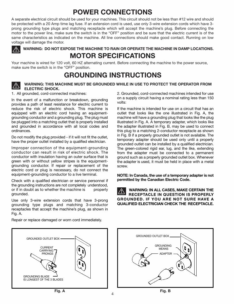
2. Grounded, cord-connected machines intended for useon a supply circuit having a nominal rating less than 150volts:
If the machine is intended for use on a circuit that has anoutlet that looks like the one illustrated in Fig. A, themachine will have a grounding plug that looks like the plugillustrated in Fig. A. A temporary adapter, which looks likethe adapter illustrated in Fig. B, may be used to connectthis plug to a matching 2-conductor receptacle as shownin Fig. B if a properly grounded outlet is not available. Thetemporary adapter should be used only until a properlygrounded outlet can be installed by a qualified electrician.The green-colored rigid ear, lug, and the like, extendingfrom the adapter must be connected to a permanentground such as a properly grounded outlet box. Wheneverthe adapter is used, it must be held in place with a metalscrew.
NOTE: In Canada, the use of a temporary adapter is notpermitted by the Canadian Electric Code.
WARNING: IN ALL CASES, MAKE CERTAIN THE RECEPTACLE IN QUESTION IS PROPERLY
GROUNDED. IF YOU ARE NOT SURE HAVE AQUALIFIED ELECTRICIAN CHECK THE RECEPTACLE.
1. All grounded, cord-connected machines:
In the event of a malfunction or breakdown, groundingprovides a path of least resistance for electric current toreduce the risk of electric shock. This machine isequipped with an electric cord having an equipment-grounding conductor and a grounding plug. The plug mustbe plugged into a matching outlet that is properly installedand grounded in accordance with all local codes andordinances.
Do not modify the plug provided - if it will not fit the outlet,have the proper outlet installed by a qualified electrician.
Improper connection of the equipment-groundingconductor can result in risk of electric shock. Theconductor with insulation having an outer surface that isgreen with or without yellow stripes is the equipment-grounding conductor. If repair or replacement of theelectric cord or plug is necessary, do not connect theequipment-grounding conductor to a live terminal.
Check with a qualified electrician or service personnel ifthe grounding instructions are not completely understood,or if in doubt as to whether the machine is properlygrounded.
Use only 3-wire extension cords that have 3-pronggrounding type plugs and matching 3-conductorreceptacles that accept the machine’s plug, as shown inFig. A.
Repair or replace damaged or worn cord immediately.
Use proper extension cords. Make sure your extension cord is in good condition and is a 3-wire extension cord whichhas a 3-prong grounding type plug and matching receptacle which will accept the machine’s plug. When using anextension cord, be sure to use one heavy enough to carry the current of the machine. An undersized cord will causea drop in line voltage, resulting in loss of power and overheating. Fig. D, shows the correct gauge to use dependingon the cord length. If in doubt, use the next heavier gauge. The smaller the gauge number, the heavier the cord.
EXTENSION CORDS
OPERATING INSTRUCTIONSFOREWORD
Delta Model 31-695 sands smoothly and efficiently from start to finish. The Delta Model 31-695 features a large 9"diameter abrasive disc, which is perfect for sanding large curves or rounding out sharp corners. The Delta Model 31-695also features an adjustable 6" belt unit, which can be operated vertically or horizontally or at any angle in-between.
UNPACKING AND CLEANINGCarefully unpack the machine and all loose items from the shipping container(s). Remove the protective coating fromall unpainted surfaces. This coating may be removed with a soft cloth moistened with kerosene (do not use acetone,gasoline or lacquer thinner for this purpose). After cleaning, cover the unpainted surfaces with a good quality householdfloor paste wax.
NOTICE: THE MANUAL COVER PHOTO ILLUSTRATES THE CURRENTPRODUCTION MODEL. ALL OTHER ILLUSTRATIONS ARE REPRESENTATIVE
ONLY AND MAY NOT DEPICT THE ACTUAL COLOR, LABELING ORACCESSORIES.
5
Fig. D
MINIMUM GAUGE EXTENSION CORDRECOMMENDED SIZES FOR USE WITH STATIONARY ELECTRIC MACHINES
Ampere Total Length Gauge ofRating Volts of Cord in Feet Extension Cord
0-6 120 up to 25 18 AWG0-6 120 25-50 16 AWG0-6 120 50-100 16 AWG0-6 120 100-150 14 AWG
6-10 120 up to 25 18 AWG6-10 120 25-50 16 AWG6-10 120 50-100 14 AWG6-10 120 100-150 12 AWG
10-12 120 up to 25 16 AWG10-12 120 25-50 16 AWG10-12 120 50-100 14 AWG10-12 120 100-150 12 AWG
12-16 120 up to 25 14 AWG12-16 120 25-50 12 AWG12-16 120 GREATER THAN 50 FEET NOT RECOMMENDED
6
UNPACKINGYour new Belt/Disc Sander and Stand is shipped complete in one container. Carefully unpack the sander, stand, andall loose items from the shipping container. Fig. 2, illustrates the sander and its component parts. Fig. 3, illustrates thecomponent parts of the stand.
A Two Upper Front and RearBraces - 11-1/2" long
B Two Lower Front and RearBraces - 17-1/8" long
C Two Upper Side Braces -21-5/16" long
D Two Lower Side Braces -26-5/8" long
E Four Legs - 27-1/2" long
F M8 Hex Nuts - (36)
G 3/8" Flat Washers - (40)
H M8 x 20mm Carriage Bolts- (32)
J M8 x 45mm Hex HeadScrews (4)
K Plastic Feet (4)
Fig. 2
Fig. 3
1. Sander with 6" x 48"SandingBelt and Backstop
2. 9" Sanding Disc
3. Drive Belt
4. Sanding Disc Plate
5. Belt and Pulley Cover
6. Disc Cover
7. M4.2 x 13mm PanheadScrews (3)
8. Plug
9. M6 x 55mm Hex SocketHeadScrews (2)
10. M6.4 Flat Washer (2)
11. M6.4 Lockwasher (2)
12. T-Wrench
13. Support Rod
14. Table Assembly
1
23
45
6
78
9
10
11
1213
14
E
A
B
C
D
F
GH
J
K
7
ASSEMBLY INSTRUCTIONSWARNING: FOR YOUR OWN SAFETY, DO NOT CONNECT THE SANDER TO THE POWER SOURCE UNTIL
THE MACHINE IS COMPLETELY ASSEMBLED AND YOU READ AND UNDERSTAND THE ENTIRE OWNERSMANUAL.
ASSEMBLING STANDIMPORTANT: ANY LETTER DESIGNATIONS THATMAY BE STAMPED ON THE BRACES OF THE STANDARE FOR PRODUCTION PURPOSES ONLY AND ARENOT USED FOR ASSEMBLING THE STAND. TOASSEMBLE THE STAND, PLEASE FOLLOW THEINSTRUCTIONS DESCRIBED BELOW. SIZES AREGIVEN TO HELP IDENTIFY THE COMPONENTS OFTHE STAND.1. Assemble the stand, as shown in Fig. 4. Align theholes in the stand and fasten the stand together byinserting a M8X20mm carriage head bolt through thehole and place a 3/8" flat washer onto the carriage headbolt and thread a M8 hex nut onto the screw and tightensecurely, repeat this process for the thirty one remainingholes. The two 11-1/2" long upper braces (A); 21-5/16"long upper braces (B); 17-1/8" long lower braces (C); and26-5/8" long lower braces (D) should be fastened to thefour 27-1/2" long legs (E). IMPORTANT: The top anglesof the upper braces (A) should be on top of the topangles of upper braces (B).2. Assemble a plastic foot (F) Fig. 4, to the bottom ofeach leg (E) as shown.
ASSEMBLING MACHINETO STANDCarefully set the sander on the stand. Align the four holeson the top of stand (A) Fig. 5, with four mounting holes atthe base of sander (B). Place a 3/8" flat washer onto aM8 x 45mm hex head screw (C), insert screw throughhole in base of sander (B) and stand (A). Place a 3/8" flatwasher onto the screw and thread a M8 hex nut onto thescrew and tighten securely, repeat this process for thethree remaining holes.
ASSEMBLING DRIVE BELTAND ADJUSTINGBELT TENSION1. With hex wrench (A) Fig. 6 supplied, loosen screw (B)and move sanding arm (C) to the vertical position; tightenscrew (B) as shown. Assemble drive belt (D) to pulleys.2. NOTE: The drive belt (D) Fig. 7, should be firm butnot too tight on the pulleys, the drive belt (D) shouldhave approximately 1/4" to 1/2" deflection in the beltat the center span on the pulleys (E) and (F) usinglight finger pressure. The drive belt (D) does notrequire excessive tension to function properly. Toadjust belt tension, loosen locknut (G) Fig. 7. Usingwrench (A) tighten or loosen adjustment screw (H) untilcorrect belt tension is obtained. Then tighten locknut (G).3. After drive belt (D) Fig. 7, is tensioned properly, movethe sanding arm to the horizontal position.
Fig. 4
Fig. 5
Fig. 6
Fig. 7
AB
CD
E
F
A
B
C
C
B
C
A
D
E
D
F
H
G
A
8
Fig. 8
Fig. 9
Fig. 11
Fig. 12
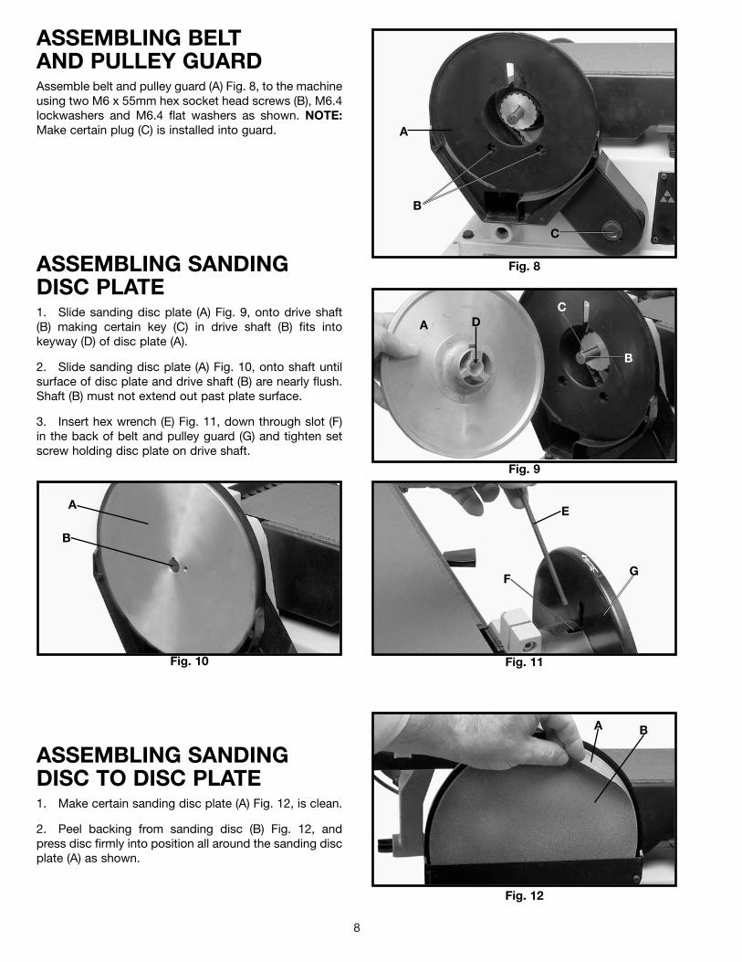
ASSEMBLING BELTAND PULLEY GUARDAssemble belt and pulley guard (A) Fig. 8, to the machineusing two M6 x 55mm hex socket head screws (B), M6.4lockwashers and M6.4 flat washers as shown. NOTE:Make certain plug (C) is installed into guard.
ASSEMBLING SANDINGDISC PLATE1. Slide sanding disc plate (A) Fig. 9, onto drive shaft(B) making certain key (C) in drive shaft (B) fits intokeyway (D) of disc plate (A).
2. Slide sanding disc plate (A) Fig. 10, onto shaft untilsurface of disc plate and drive shaft (B) are nearly flush.Shaft (B) must not extend out past plate surface.
3. Insert hex wrench (E) Fig. 11, down through slot (F)in the back of belt and pulley guard (G) and tighten setscrew holding disc plate on drive shaft.
Fig. 10
ASSEMBLING SANDINGDISC TO DISC PLATE1. Make certain sanding disc plate (A) Fig. 12, is clean.
2. Peel backing from sanding disc (B) Fig. 12, andpress disc firmly into position all around the sanding discplate (A) as shown.
A
B
C
A D
B
C
A
B
E
GF
BA
9
Fig. 13
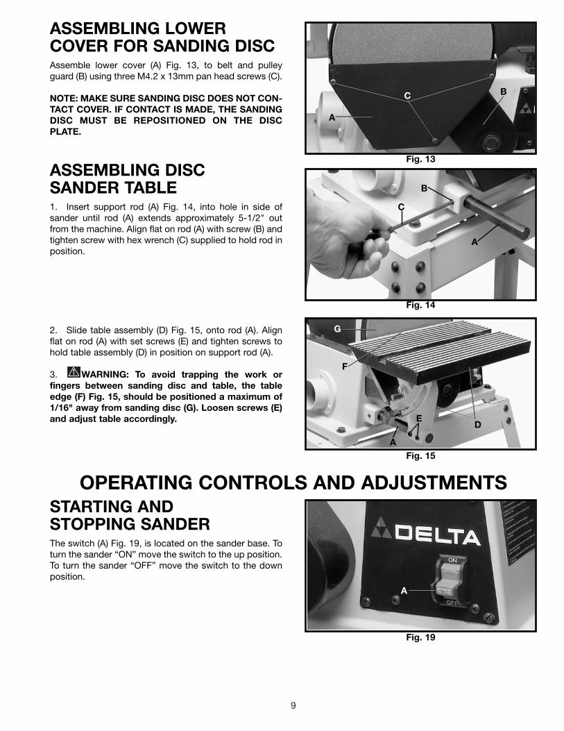
ASSEMBLING LOWERCOVER FOR SANDING DISCAssemble lower cover (A) Fig. 13, to belt and pulleyguard (B) using three M4.2 x 13mm pan head screws (C).
NOTE: MAKE SURE SANDING DISC DOES NOT CON-TACT COVER. IF CONTACT IS MADE, THE SANDINGDISC MUST BE REPOSITIONED ON THE DISCPLATE.
Fig. 14
Fig. 15
ASSEMBLING DISCSANDER TABLE1. Insert support rod (A) Fig. 14, into hole in side ofsander until rod (A) extends approximately 5-1/2" outfrom the machine. Align flat on rod (A) with screw (B) andtighten screw with hex wrench (C) supplied to hold rod inposition.
2. Slide table assembly (D) Fig. 15, onto rod (A). Alignflat on rod (A) with set screws (E) and tighten screws tohold table assembly (D) in position on support rod (A).
3. WARNING: To avoid trapping the work orfingers between sanding disc and table, the tableedge (F) Fig. 15, should be positioned a maximum of1/16" away from sanding disc (G). Loosen screws (E)and adjust table accordingly.
C B
A
C
B
A
G
A
E
F
D
OPERATING CONTROLS AND ADJUSTMENTS
Fig. 19
STARTING ANDSTOPPING SANDERThe switch (A) Fig. 19, is located on the sander base. Toturn the sander “ON” move the switch to the up position.To turn the sander “OFF” move the switch to the downposition.
A
10
Fig. 20
LOCKING SWITCH INTHE “OFF” POSITIONIMPORTANT: When the machine is not in use, theswitch should be locked in the “OFF” position toprevent unauthorized use. This can be done bygrasping the switch toggle (B) and pulling it out of theswitch, as shown in Fig. 20. With the switch toggle (B)removed, the switch will not operate. However, shouldthe switch toggle be removed while the sander isrunning, it can be turned “OFF” once, but cannot berestarted without inserting the switch toggle (B).
B
Fig. 21
TRACKING THESANDING BELT1. Turn the switch “ON” and “OFF” and check to see ifthe sanding belt tends to move to one side or the otheron the two sanding drums. If the belt does not move toone side or the other and rides on the center of thesanding drums the belt is tracking properly.
2. If the sanding belt moves toward the disc, turn thetracking knob (A) Fig. 21, counterclockwise 1/4 turn.
3. If the sanding belt moves away from the disc, turnthe tracking knob (A) Fig. 21, clockwise 1/4 turn.
4. Turn the switch “ON” and “OFF” again, and check tosee if the sanding belt moves to one side or the otherand readjust tracking knob if necessary.
CHANGING POSITION OFSANDING ARMThe sanding arm (A) can be used in the horizontalposition, as shown in Fig. 22; vertical position, as shownin Fig. 23; or any angle in between by loosening screw(B) with hex wrench (C) supplied, positioning the arm (A)to the desired angle, and tightening screw (B).
Fig. 22
Fig. 23
A
BA
C
A
B
11
Fig. 24
Fig. 25
Fig. 26
ADJUSTING SANDINGARM STOPA positive stop is provided to position the sanding armlevel with the workbench when the arm is in thehorizontal position.
1. DISCONNECT MACHINE FROM POWER SOURCE.
2. Place the sanding arm as far as possible in the hori-zontal position.
3. Place a level (A) on the sanding belt and check to seeif the arm is level, as shown in Fig. 24.
4. If an adjustment is necessary, loosen lock nut (B)Fig. 24, and turn sanding arm stop (C) in or out until thesanding arm is level. Then tighten lock nut (B).
ADJUSTING BACKSTOPSQUARE WITHSANDING BELT1. DISCONNECT MACHINE FROM POWER SOURCE.
2. When making this adjustment make sure the belttension lever (A) Fig. 25, is all the way to the left in thetensioned position, as shown.
3. Place a square (B) Fig. 26, on the sanding belt withone end of the square against the backstop, and checkto see if the backstop is square with the sanding belt.
4. If an adjustment is necessary, loosen two screws (C)Fig. 26, and adjust the backstop accordingly. Tightenscrews (C) after adjustment is made.
Fig. 27
TILTING THE TABLE1. DISCONNECT MACHINE FROM POWER SOURCE.
2. The table can be tilted up to 45 degrees to the rightby loosening the table lock knob (A) Fig. 27, tilting thetable to the desired angle, and tightening table lockknob (A).
3. WARNING: AFTER TILTING, THE TABLE AS-SEMBLY MUST BE REPOSITIONED ON THESUPPORT ROD (B) FIG. 27, TO PROVIDE AMAXIMUM OF 1/16 INCH DISTANCE BETWEEN THESANDING DISC (C), AND THE EDGE (D) OF THETABLE, TO AVOID TRAPPING THE WORK ORFINGERS BETWEEN THE DISC AND TABLE. TOREPOSITION THE TABLE ASSEMBLY, LOOSEN TWOSCREWS (E) AND/OR SCREW (F), MOVE TABLEASSEMBLY ON ROD (B), AND TIGHTEN SCREWS (E)AND/OR (F).
BC
A
A
C
B
C
D
A
E
B
F
12
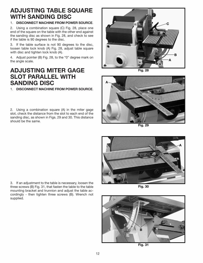
ADJUSTING TABLE SQUAREWITH SANDING DISC1. DISCONNECT MACHINE FROM POWER SOURCE.
2. Using a combination square (C) Fig. 28, place oneend of the square on the table with the other end againstthe sanding disc as shown in Fig. 28, and check to seeif the table is 90 degrees to the disc.
3. If the table surface is not 90 degrees to the disc,loosen table lock knob (A) Fig. 28, adjust table squarewith disc and tighten lock knob (A).
4. Adjust pointer (B) Fig. 28, to the “0” degree mark onthe angle scale.
ADJUSTING MITER GAGESLOT PARALLEL WITHSANDING DISC1. DISCONNECT MACHINE FROM POWER SOURCE.
2. Using a combination square (A) in the miter gageslot, check the distance from the slot to each end of thesanding disc, as shown in Figs. 29 and 30. This distanceshould be the same.
3. If an adjustment to the table is necessary, loosen thethree screws (B) Fig. 31, that fasten the table to the tablemounting bracket and trunnion and adjust the table ac-cordingly - then tighten three screws (B). Wrench notsupplied.
Fig. 28
Fig. 29
Fig. 31
Fig. 30
A
B
C
A
A
B
13
Fig. 32
Fig. 33
Fig. 34
Fig. 35
ACCESSORY MITER GAGEAn accessory miter gage is available for your machineand is used with the disc table. The miter gage body (A)Fig. 32, can be tilted right or left for angle or mitersanding by loosening lock knob (B), and rotating mitergage body to the desired angle. Tighten lock knob (B).
DUST SPOUTA dust spout (A) Fig. 35, is supplied with your sander andcan easily be connected to a standard shop vacuumhose. The inside diameter opening of the dust spout (A)is 2-1/4 inches.
USING TABLE ASSEMBLYWITH SANDING BELTWhen the sanding arm (A) Fig. 33, is in the verticalposition, the complete table assembly (B) can be movedfrom the disc unit to the belt unit as follows:
1. Remove backstop (C) Fig. 33, from the machine.
2. Loosen screw (D) Fig. 33, and carefully remove sup-port bar (E) and table assembly (B) from the disc unit.
3. Loosen set screw (F) Fig. 34, and insert support bar(E) and table assembly (B) into hole (G) Figs. 33 & 34, onbelt unit. Tighten set screw (F) to hold support bar andtable assembly in position.
WARNING: THE TABLE EDGE (H) FIG. 34, MUSTBE POSITIONED A MAXIMUM OF 1/16" AWAY FROMSANDING BELT (J) TO AVOID TRAPPING THE WORKOR FINGERS BETWEEN THE TABLE AND SANDINGBELT.
A
B
A
C
B
D
E
B
F
GE
H
J
A
G
14
Fig. 36
Fig. 37
Fig. 38
Fig. 39
ADJUSTING DUST SHIELDIf your sander is connected to a dust collection system,the sander is equipped with a manually operated dustshield (A) Fig. 36, which must be adjusted to suit thesanding operation.
1. If you are sanding with the disc, push in on dustshield (A) Fig. 36.
2. If you are sanding on the belt, pull dust shield (A)Fig. 37, outward.
WRENCH STORAGEA hole is provided in the stand for storing the hex wrench(A) Fig. 38, supplied with the sander.
REMOVING UPPERSANDING DRUM GUARDThe upper sanding drum guard (A) Fig. 39, can beremoved easily, if necessary, when sanding inside curvedwork on the idler drum or changing belts.
1. Pull outward on guard (A).
2. After sanding operation is completed or beltchanged, replace guard (A) Fig. 39, on two studs (B),one of which is shown.
A
A
A
BA
15
Fig. 40
Fig. 41
Fig. 42
Fig. 43
5. Slide new 6" x 48" sanding belt (F) Fig. 43, over bothsanding drums (G), making sure the belt (F) will travel inthe direction of the arrow located on the inside of thebelt.
6. Re-apply belt tension by sliding tension lever (E)Fig. 42, to the left.
7. Replace support bracket, backstop and uppersanding drum guard which were removed in STEPS 2and 3.
8. Connect electrical power to the sander and check tosee if the belt is tracking properly. If not, refer to section“TRACKING THE SANDING BELT.”
4. Slide tension lever (E) Fig. 42, to the right to releasetension on sanding belt (F). Remove sanding belt (F) fromboth sanding drums.
REPLACING SANDING BELT1. DISCONNECT MACHINE FROM POWER SOURCE.
3. Loosen two screws (C) Fig. 40, and remove supportbracket (D). Fig. 41 illustrates backstop and supportbracket removed from the machine. C
D
B
A
E
F
G F G
16
REPLACING SANDING DISCWhen it becomes necessary to replace the sanding disc, proceed as follows:
Fig. 44
1. DISCONNECT MACHINE FROM POWER SOURCE.2. Loosen screw (A) Fig. 44, and remove table assem-bly (B).3. Remove three screws (C) Fig. 45, and lower cover(D).4. Peel off old disc (E) as shown in Fig. 46.5. Make sure the disc plate (F) Fig. 46, is clean and peelbacking from new sanding disc. Press the new sandingdisc firmly into position on disc plate (F) and replacelower cover and table assembly which were removed inSTEPS 2 and 3.
Fig. 45 Fig. 46
OPERATION
Fig. 48Fig. 47
SURFACING OR EDGE SANDING WITH SANDING BELTWhen surfacing (see Fig. 47), or edge sanding (see Fig. 48), the sanding arm is in the horizontal positionand the backstop (A) Fig. 47 and Fig. 48, must always be used to prevent the workpiece from beingcarried along the belt. Always hold the workpiece firmly, keeping your fingers away from the sandingbelt. Always keep the end of the workpiece against the backstop and move the workpiece evenlyacross the sanding belt. Apply only enough pressure to allow the sanding belt to remove material. Useextra caution when sanding very thin pieces.
WARNING: THE EDGE OF THE BACKSTOP MUST BE POSITIONED A MAXIMUM OF 1/16INCH AWAY FROM THE SANDING BELT TO AVOID TRAPPING THE WORK OR FINGERSBETWEEN THE BACKSTOP AND SANDING BELT.
A
B
D
C
E
F
A A
17
Fig. 49
SANDING INSIDE CURVESInside curves can be sanded on the top sanding drum,as shown in Fig. 49.
NOTE: Replace sanding drum guard after sandingoperation is completed!
Fig. 50
SANDING OUTSIDE CURVESOutside curves should be sanded on the sanding disc asshown in Fig. 50. WARNING: ALWAYS SAND ONTHE LEFT (DOWNWARD) SIDE OF THE SANDINGDISC, AS SHOWN. SANDING ON THE RIGHT(UPWARD) SIDE OF THE SANDING DISC COULDCAUSE THE WORKPIECE TO FLY UP, WHICH COULDBE HAZARDOUS.
WARNING: THE EDGE OF THE TABLE MUST BEPOSITIONED A MAXIMUM OF 1/16 INCH AWAYFROM THE SANDING DISC TO AVOID TRAPPINGTHE WORK OR FINGERS BETWEEN THE TABLE ANDSANDING DISC.
Fig. 51
END SANDINGWITH THE DISCWhen sanding the ends of narrow workpieces use thesanding disc and the accessory miter gage, as shown inFig. 51. Move the work from the center to the left side ofthe sanding disc. WARNING: ALWAYS SAND ONTHE LEFT (DOWNWARD) SIDE OF THE SANDINGDISC, AS SHOWN. SANDING ON THE RIGHT(UPWARD) SIDE OF THE SANDING DISC COULDCAUSE THE WORKPIECE TO FLY UP, WHICH COULDBE HAZARDOUS.
WARNING: THE EDGE OF THE TABLE MUST BEPOSITIONED A MAXIMUM OF 1/16 INCH AWAYFROM THE SANDING DISC TO AVOID TRAPPINGTHE WORK OR FINGERS BETWEEN THE TABLE ANDSANDING DISC.
Fig. 52
END SANDING WIDEWORKPIECES WITH THEBELTWhen sanding the ends of wide workpieces, it is moreconvenient to use the sanding belt with the sanding armin the vertical position and the table assembly moved tothe sanding belt, as shown in Fig. 52. See sections titled“CHANGING POSITION OF SANDING ARM” and“USING TABLE ASSEMBLY WITH SANDING BELT.”
For more accurate work use the accessory miter gageand move the work evenly across the sanding belt, asshown in Fig. 52.
WARNING: THE EDGE OF THE TABLE MUST BEPOSITIONED A MAXIMUM OF 1/16 INCH AWAYFROM THE SANDING BELT TO AVOID TRAPPINGTHE WORK OR FINGERS BETWEEN THE TABLE ANDSANDING BELT.
18
Two Year Limited WarrantyDelta will repair or replace, at its expense and at its option, any Delta machine, machine part, or machine accessory whichin normal use has proven to be defective in workmanship or material, provided that the customer returns the productprepaid to a Delta factory service center or authorized service station with proof of purchase of the product within twoyears and provides Delta with reasonable opportunity to verify the alleged defect by inspection. Delta may require thatelectric motors be returned prepaid to a motor manufacturer’s authorized station for inspection and repair or replacement.Delta will not be responsible for any asserted defect which has resulted from normal wear, misuse, abuse or repair oralteration made or specifically authorized by anyone other than an authorized Delta service facility or representative. Underno circumstances will Delta be liable for incidental or consequential damages resulting from defective products. Thiswarranty is Delta’s sole warranty and sets forth the customer’s exclusive remedy, with respect to defective products; allother warranties, express or implied, whether of merchantability, fitness for purpose, or otherwise, are expresslydisclaimed by Delta.
Printed in U.S.A.
PARTS, SERVICE OR WARRANTY ASSISTANCEAll Delta Machines and accessories are manufactured to high quality standards and are serviced by a networkof Porter-Cable • Delta Factory Service Centers and Delta Authorized Service Stations. To obtain additionalinformation regarding your Delta quality product or to obtain parts, service, warranty assistance, or the locationof the nearest service outlet, please call 1-800-223-7278 (In Canada call 1-800-463-3582).
ACCESSORIESA complete line of accessories is available from your Delta Supplier, Porter-Cable • Delta Factory Service Centers,and Delta Authorized Service Stations. Please visit our Web Site www.deltamachinery.com for a catalog orfor the name of your nearest supplier.
WARNING: Since accessories other than those offered by Delta have not been tested with this product, use of such accessories could be hazardous. For safest operation, only Delta recommended accessories should be used with this product.