49
1 Courtesy of Khairul Saleh
| Date post: | 08-Dec-2015 |
| Category: |
Documents |
| Upload: | nita-susanti |
| View: | 216 times |
| Download: | 0 times |

1
Courtesy of Khairul Saleh

Fisika fMIPA UNSRI 2
These include: Amplifiers for amplifying the transducer output.
which may be small. Filters, for filtering out unwanted portions of the
signal. AD/DA converters, for converting analog type
signals to digital form
1. Introduction

Fisika fMIPA UNSRI 3
Amplifiers are intermediate elements that increase the magnitude of the signal from a transducer so that it can be conveniently displayed or recorded. These may be of mechanical, hydraulic, pneumatic, optical or eletricallelectronic types, depending on the type of transducer. In cases where a reduction is needed in the magnitude of the signal from the transducers, these are called attenuators.
2. Amplifier
Fisika fMIPA UNSRI 4
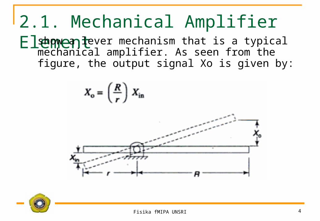
2.1. Mechanical Amplifier Elementshow a lever mechanism that is a typical
mechanical amplifier. As seen from the figure, the output signal Xo is given by:

Fisika fMIPA UNSRI 5
2. 2. Hydroulic Amplifying Elementshows a typical hydraulic type element, in which
the output signal X, is given by
Fisika fMIPA UNSRI 6
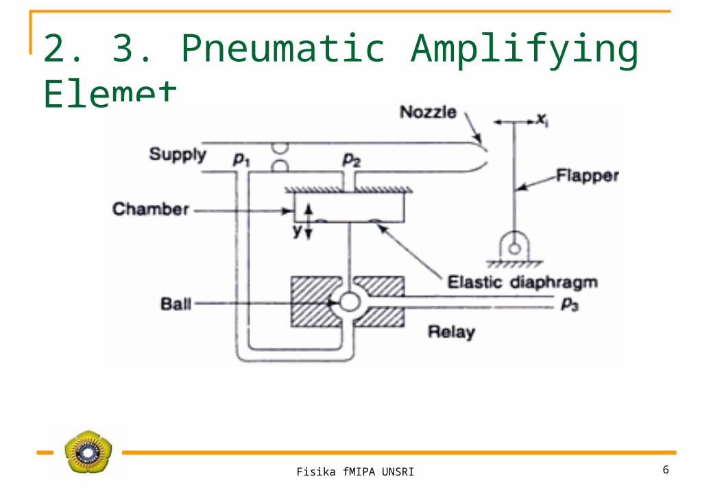
2. 3. Pneumatic Amplifying Elemet

Fisika fMIPA UNSRI 7
2. 4. Optical Amplifying Element A ray of light gets deflected by 2 from a mirror attached to the moving
member and the distance X0 moved by the light spot on the scale is given by
where R is the distance between the scale and the mirror. By proper choice of the distance R. X0 can be made as large as desired.
Fisika fMIPA UNSRI 8
2. 5. Electrical Amplifying ElementCurrently, most of the electrical amplifiers are either transistor based or
employ suitable integrated circuits (ICs) or both Vacuum tubes have now become obsolete and are employed in certain special applications only. Presently a wide variety of amplifiers are available to meet the specific requirements in the signal conditioning element of the instrument systems. The following are the characteristics of an ideal amphfer i.e. it should have:
(i) infinite input impedance, i.e. it should have no loading effect on the transducer.
(ii) zero output impedance(iii) a very large gain (theoretically infinite) to improve resolution(iv) zero output for zero input(v) ability to filter spurious inputs(vi) instant response.

Fisika fMIPA UNSRI 9
Fisika fMIPA UNSRI 10
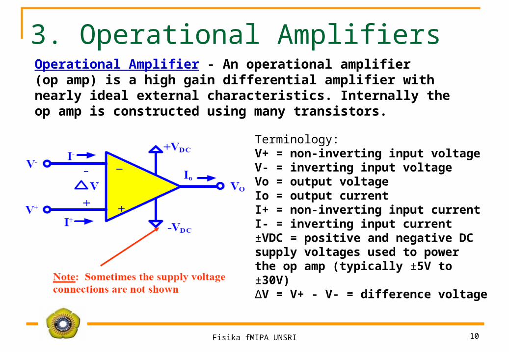
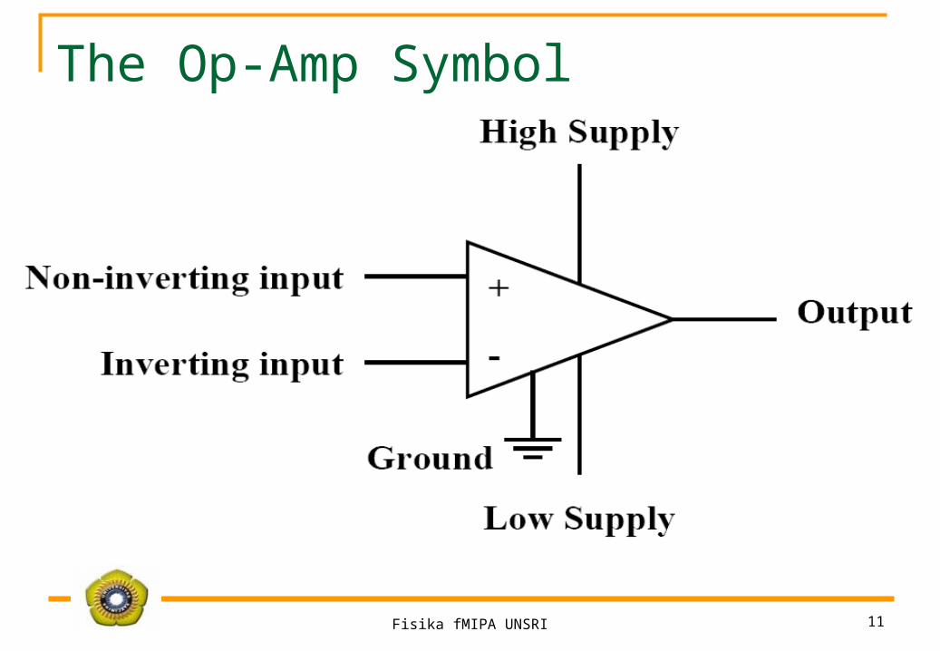
Operational Amplifier - An operational amplifier(op amp) is a high gain differential amplifier withnearly ideal external characteristics. Internally theop amp is constructed using many transistors.
Terminology:V+ = non-inverting input voltageV- = inverting input voltageVo = output voltageIo = output currentI+ = non-inverting input currentI- = inverting input current±VDC = positive and negative DCsupply voltages used to powerthe op amp (typically ±5V to±30V)ΔV = V+ - V- = difference voltage
3. Operational Amplifiers
Fisika fMIPA UNSRI 11
The Op-Amp Symbol

Fisika fMIPA UNSRI 12
Internal Model of a Real Op-Amp
Zin is the input impedance (very large ≈ 2 MΩ)Zout is the output impedance (very small ≈ 75 Ω)Aol is the open-loop gain

Fisika fMIPA UNSRI 13
Op-Amps Nearly ideal
An operational amplifier has a very high input impedance and a very high gain.
High gain: up to 105-106 High input impedance: 4MΩ Low output impedance: ∼500 Ω Stable
Op-Amp is short for operational amplifier. An operational amplifier is modeled as a voltage controlled voltage source. The exact gain is often unpredictable.
Fisika fMIPA UNSRI 14
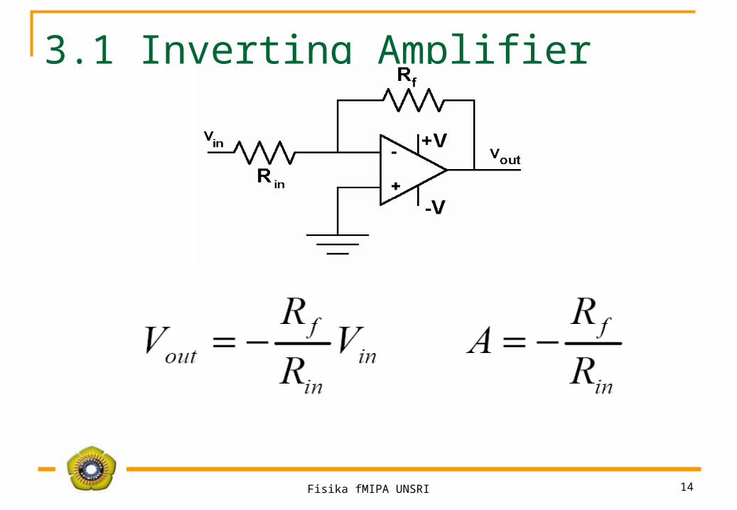
3.1 Inverting Amplifier

Fisika fMIPA UNSRI 15
3.2 Non-inverting Amplifier

Fisika fMIPA UNSRI 16
3.3 Differential (or Difference) Amplifier

Fisika fMIPA UNSRI 17
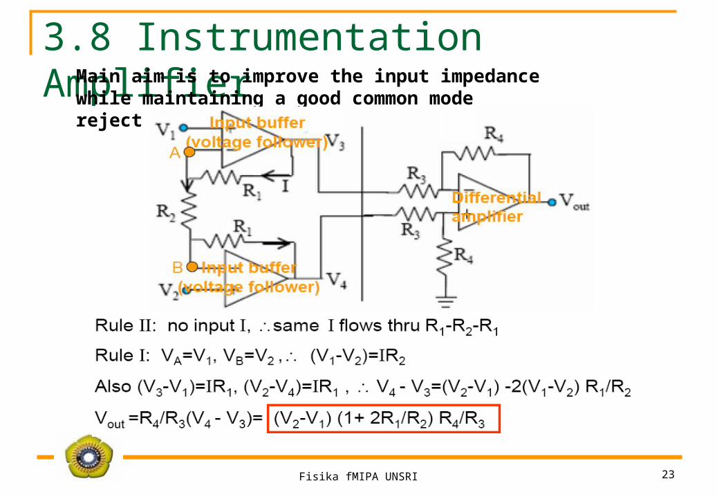
3.4 Voltage followerThis is simply a noninverting amplifier with Rg= ∞ and Rf = 0
This unity gain amplifier is sometimes used asan input buffer as it has very high inputimpedance and low output impedance
Fisika fMIPA UNSRI 18
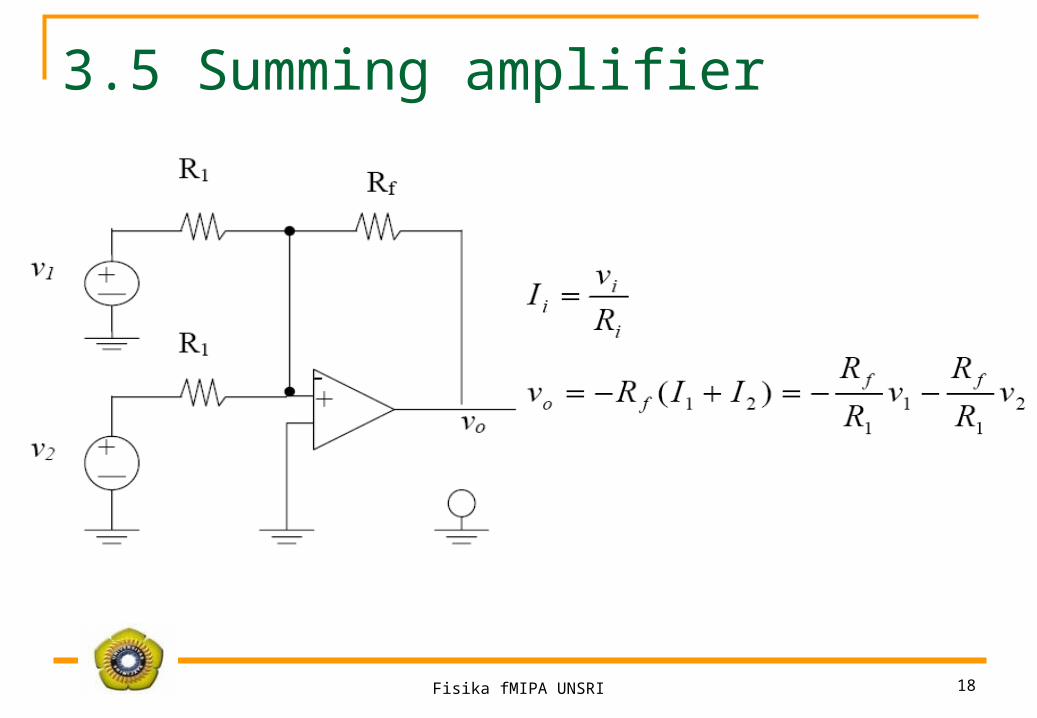
3.5 Summing amplifier
Fisika fMIPA UNSRI 19
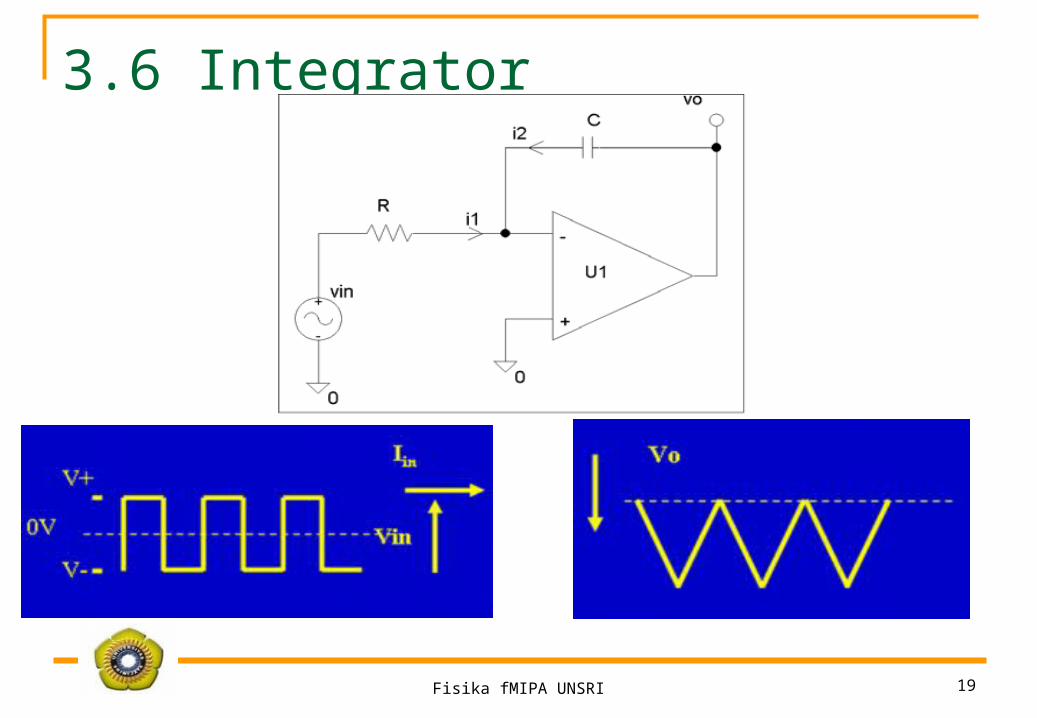
3.6 Integrator

Fisika fMIPA UNSRI 20
IntegratorSince the inverting input is at virtual ground
Applying Kirchhoff's Current Law (KCL) at the inverting input

Fisika fMIPA UNSRI 21
3.7 Differentiator

Fisika fMIPA UNSRI 22
DifferentiatorSince the inverting input is at virtual ground
Applying KCL at the inverting input
Fisika fMIPA UNSRI 23
3.8 Instrumentation AmplifierMain aim is to improve the input impedance while maintaining a good common mode rejection
Fisika fMIPA UNSRI 24
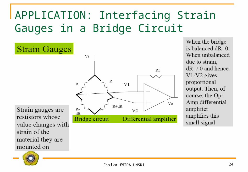
APPLICATION: Interfacing Strain Gauges in a Bridge Circuit
Fisika fMIPA UNSRI 25
4. Filter
Macam-macam Filter Low-pass Filters (Tapis Lolos Rendah) High-pass Filters (Tapis Lolos Tinggi) Band-pass Filters (Tapis Lolos Pita) Band-stop Filters (Tapis Sekat Pita)

Fisika fMIPA UNSRI 26
Filters: Intuitive Understanding
Transfer Function:
Impedance:
Low-pass filters: CRVi Vo

Fisika fMIPA UNSRI 27
Filters: Intuitive Understanding
Low-pass filters:
L
RVi Vo
Dimensionless Frequency:
At low frequency:
At high frequency:
Fisika fMIPA UNSRI 28
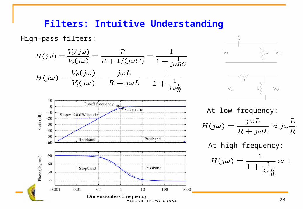
Filters: Intuitive Understanding
High-pass filters: C
R VoVi
VoL
R
Vi
At low frequency:
At high frequency:

Fisika fMIPA UNSRI 29
Filters: Intuitive Understanding
C
R
L
VoVi
Band-pass or Band-stop Filters:
C
R VoVi
L
RVi Vo
}High-pass
Low-pass
Low-passHigh-pass
High-passLow-pass

Fisika fMIPA UNSRI 30
Filters: Intuitive Understanding
C
R
L
VoVi
Band-pass or Band-stop Filters:
Band-pass Band-stopHigh-passLow-pass

Fisika fMIPA UNSRI 31
Complex Frequency and Laplace Transform
Phasor and Impedance
What if
Define complex frequency

Fisika fMIPA UNSRI 32
Transfer FunctionC
R
L
VoVi
Fisika fMIPA UNSRI 33
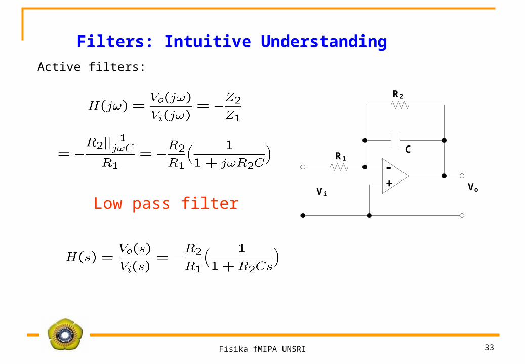
Filters: Intuitive Understanding
Active filters:
CR1
ViVo
+-
R2
Low pass filter
Fisika fMIPA UNSRI 34
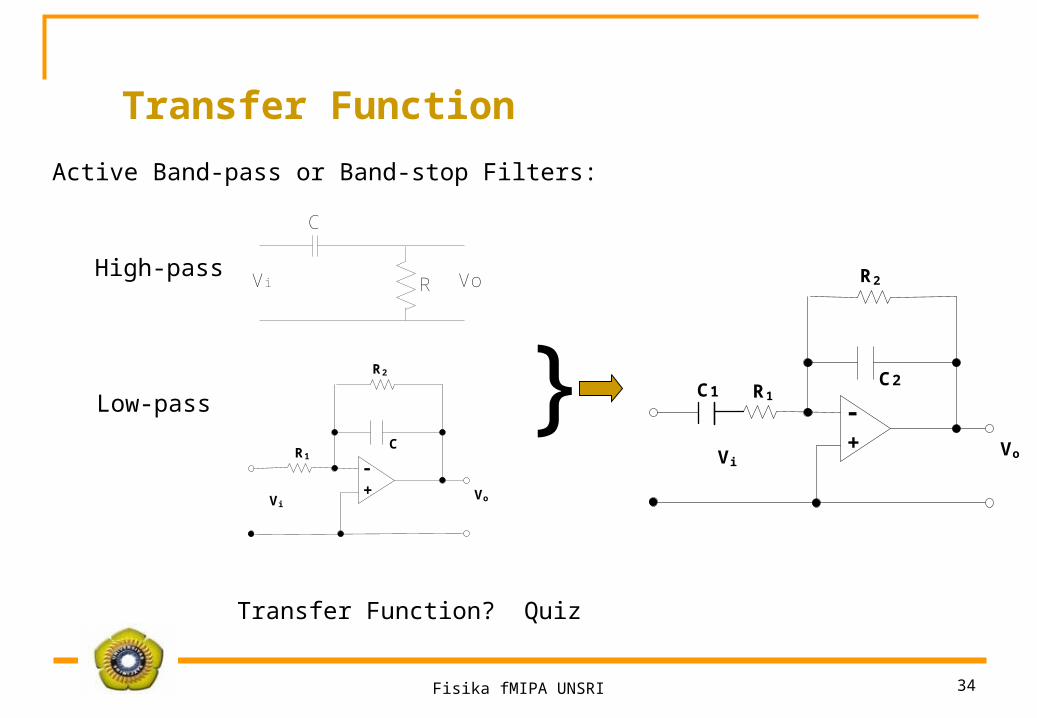
Active Band-pass or Band-stop Filters:
CR1
ViVo
+-
R2
C
R VoVi
}High-pass
Low-passC2
R1
ViVo
+-
R2
C1
Transfer Function? Quiz
Transfer Function
Fisika fMIPA UNSRI 35
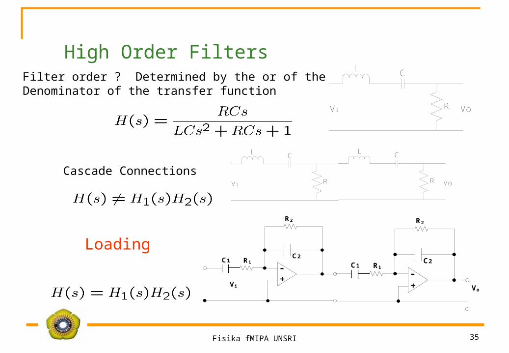
Filter order ? Determined by the or of the Denominator of the transfer function
Cascade Connections
High Order FiltersC
R
L
VoVi
C
R
L
Vi
C
R
L
Vo
C2R1
Vi+-
R2
C1 C2R1
Vo+-
R2
C1
Loading
Fisika fMIPA UNSRI 36
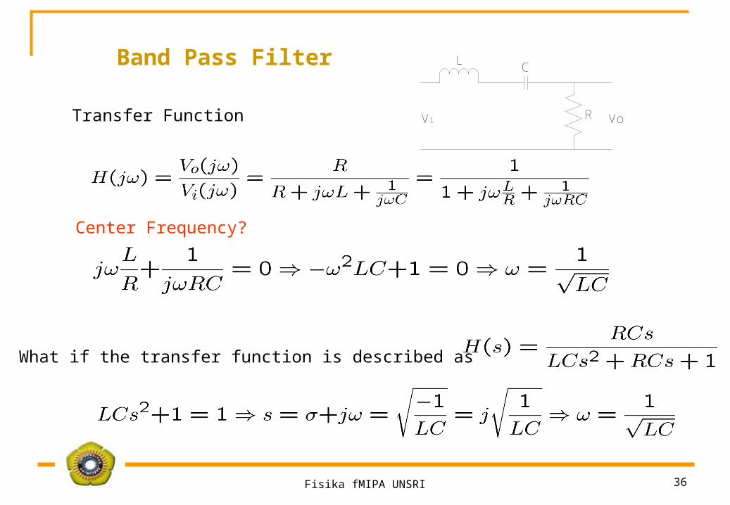
Band Pass Filter C
R
L
VoVi
Center Frequency?
Transfer Function
What if the transfer function is described as
Fisika fMIPA UNSRI 37
5. ADC dan DAC
ADC : A/D Converter ; Analog to Digital Converters : Pengubah besaran /kuantitas/ sinyal analog (sinyal kontinue) menjadi sinyal digital (sinyal diskrit).
DAC : D/A Converter ; Digital to Analog Converter : Pengubah besaran / sinyal digital menjadi sinyal Analog.
Fisika fMIPA UNSRI 38
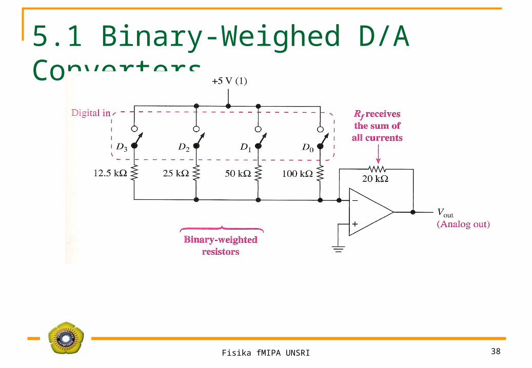
5.1 Binary-Weighed D/A Converters

Fisika fMIPA UNSRI 39
5.2. R/2R Ladder D/A Converters

Fisika fMIPA UNSRI 40
5.3 Integreted-Circuit D/A Converters

Fisika fMIPA UNSRI 41
IC D/A C MC1408
Fisika fMIPA UNSRI 42
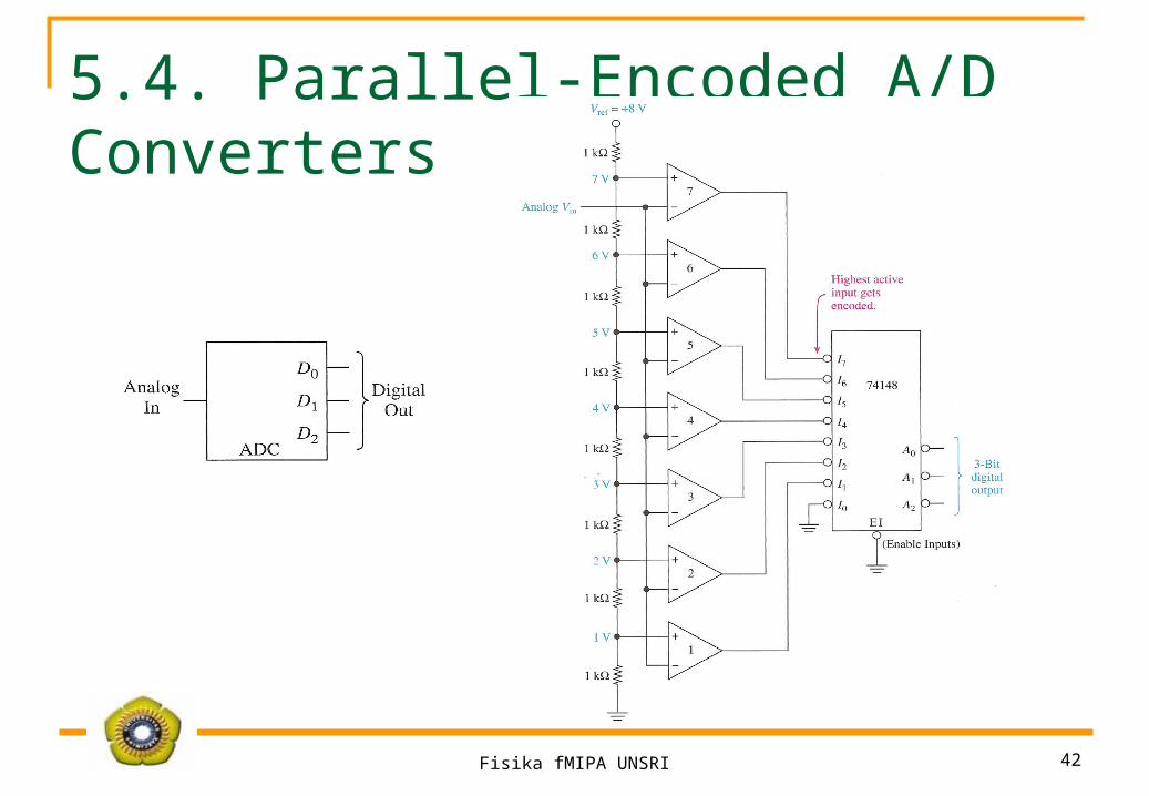
5.4. Parallel-Encoded A/D Converters
Fisika fMIPA UNSRI 43
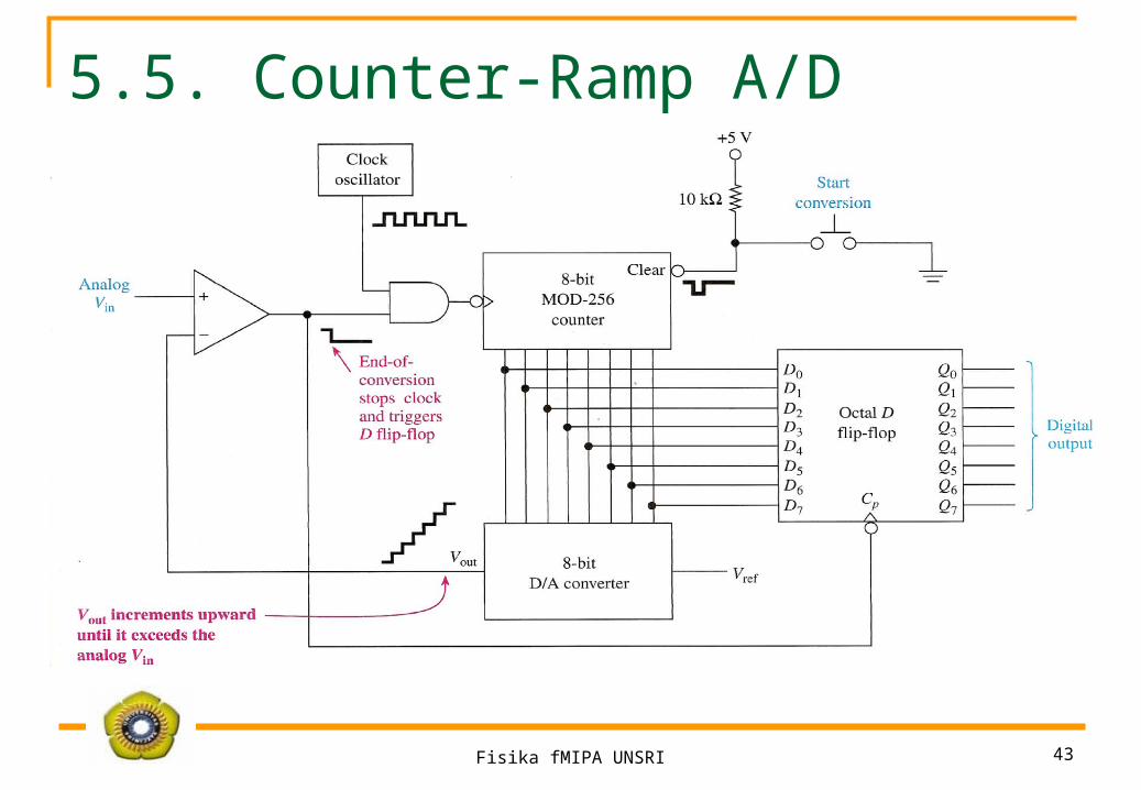
5.5. Counter-Ramp A/D Converters

Fisika fMIPA UNSRI 44
5.6. Successive-Approximation A/D C
Fisika fMIPA UNSRI 45
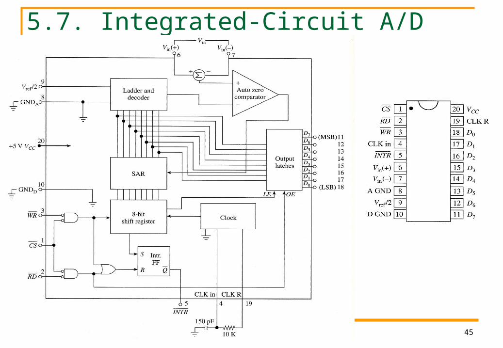
5.7. Integrated-Circuit A/D Converters

Fisika fMIPA UNSRI 46
IC ADC 0804

Fisika fMIPA UNSRI 47
Data Acquisition System

Fisika fMIPA UNSRI 48
Sumber
Fisika fMIPA UNSRI 49


