8
6 Phase Power Analyzer Competitive Analysis WT1800E PPA3500 series

6 Phase Power Analyzer Competitive Analysis
WT1800E
PPA3500 series
2
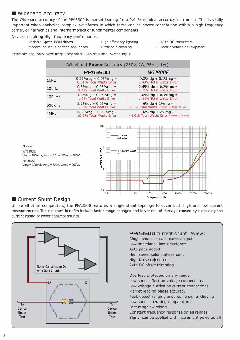
■ Wideband Accuracy The Wideband accuracy of the PPA3500 is market leading for a 0.04% nominal accuracy instrument. This is vitally important when analyzing complex waveforms in which there can be power contribution within a high frequency carrier, or harmonics and interharmonics of fundamental components.
Devices requiring High frequency performance: - Variable Speed PWM drives - High efficiency lighting - DC to DC convertors - Modern inductive heating appliances - Ultrasonic cleaning - Electric vehicle development Example accuracy over frequency with 230Vrms and 2Arms input
■ Current Shunt Design Unlike all other competitors, the PPA3500 features a single shunt topology to cover both high and low current measurements. The resultant benefits include faster range changes and lower risk of damage caused by exceeding the current rating of lower capacity shunts.
PPA3500 current shunt review:Single shunt on each current inputLow impedance low inductance Auto peak detectHigh speed solid state rangingHigh Noise rejectionAuto DC offset trimming Overload protected on any rangeLow shunt effect on voltage connectionsLow voltage burden on current connectionsMarket leading phase accuracyPeak detect ranging ensures no signal clippingLow shunt operating temparatureFast range switchingConstant frequency response on all rangesSignal can be applied with instrument powered off
Noise Cancellation Op Amp Gain Circuit
To Device Under Test
To Device Under Test
Wideband Power Accuracy (230V, 2A, PF=1, 1yr)
PPA3500 WT1800E
1kHz 0.21%rdg + 0.05%rng =0.31% Total Watts Error
0.3%rdg + 0.1%rng =0.43% Total Watts Error
10kHz 0.3%rdg + 0.05%rng =0.4% Total Watts Error
0.45%rdg + 0.2%rng =0.71% Total Watts Error
100kHz 1.2%rdg + 0.05%rng =1.3% Total Watts Error
1.05%rdg + 0.3%rng =1.44% Total Watts Error
500kHz 5.2%rdg + 0.05%rng =5.5% Total Watts Error
6%rdg + 1%rng =7.3% Total Watts Error (>200kHz 5A only)
1MHz 10.2%rdg + 0.05%rng =10.3% Total Watts Error
42%rdg + 2%rng = 44.6% Total Watts Error (>200kHz 5A only)
Notes:
WT1800E:Vrng = 300Vrms, Arng = 2Arms, VArng = 600VA
PPA3500: Vrng = 300Vpk, Arng = 3Apk, VArng = 900VA

3
WT1800E current shunt review: One of two input elements may be selected - 5Arms or 50Arms. Each of the elements feature a single current shunt design but are limited in two key respects: 1. Limited peak current rating. 5A element has 10Apk continuous rating 50A element has 150Apk continuous rating This low crest factor is a limitation in applications with high levels of harmonic distortion or pulsed low duty cycle power demand. (PPA3500 - 20Arms 300Apk or 30Arms 1000Apk) 2. Limited phase accuracy. On both input elements, poor wideband phase accuracy and limited high frequency performance imply considerable parasitic reactance. (The proprietary current shunt design in PPA units exhibit parastic inductance below 1nH which permits exceptioanal high frequency performance and leading phase accuracy)
To Device Under Test
To Device Under Test
100mΩ
To Device Under Test
To Device Under Test
2mΩ
■ Why do some analyzers use multiple ranges? The N4L Noise Cancellation circuit is unique in the industry, analyzers without this solid state circuit design typically use multiple shunts of varying impedances in order to distinguish a measured signal from the inherent noise within the measurement circuit. This is performed through the use of higher shunt impedances, which raises the measured waveform out of the noise floor. Inevitably however, the increased shunt impedance reduces the maximum current rating and increases measurement burden upon the test circuit.
50A Input Element
5A Input Element
■ Phase Accuracy Phase accuracy is of fundamental importance for any power measurement, the table below details the phase angle accuracies of each test instrument.
Phase Angle Accuracy
PPA3500 WT1800EPhase Accuracy @ 50Hz
0.005 deg 1.147 deg

4
■ WT1800E Phase Accuracy CalculationThe Yokogawa WT1800E Phase Accuracy Specification is given in the datasheet extract below;
λ = Power Factor, θ = Phase angle between voltage and current
Note : Influence of power factor when λ=0 is given as;
Yokogawa state that their phase angle specification is dependent upon "Influence of power factor", this parameter is a "design value" outside the frequency range 45 to 66Hz, therefore there is no
phase accuracy specification outside this range. N4L specify phase accuracy throughout the entire frequency range of the instrument (10mHz to 1MHz)
Accuracy of Power Factor at unity power factor:±[(λ-λ/1.002) + |cosθ - cos{θ + sin-1(0.1/100)|]±[(1-1/1.002) + |cos0 - cos{0 + sin-1(0.1/100)}|]±[(1.99960008x10-4) + |1 - 0.9999999998|]±[(1.99960008x10⁻⁴) + 5x10⁻⁷]±0.0002 PFcos-1 (1-0.0002) = 1.15 deg
Accuracy of Phase Angle at unity power factor:±[|θ-{cos-1(λ/1.0002)|+sin-1{(0.1/100)}]±[|0-{cos-1(0.99980004)|+sin-1{(0.001)}]±[1.14+0.0573] = 1.203 deg
The phase angle error calculated from the power factor and phase angle accuracy specifications are inconsistent but more importantly, they both exceed 1deg. For any phase sensitive application 1 degree phase error would be a problem. Fo r c o m p a r i s o n , t h e PPA3500 standard phase error is 0.005deg.

5
■ Harmonic AnalysisThe PPA3500 Utilises DFT (Discrete Fourier Transform) Harmonic Analysis techniques, the WT1800E utilises an FFT.
Harmonic Analysis TechniquePPA3500 WT1800E
DFT FFT
Analyzers utilising the DFT algorithm are able to achieve more accurate harmonic measurements than those using an FFT process. While similar in principle, differences in the sample window and associated processing techniques result in imperfect sychronisation or 'Harmonic Leakage'. We illustrate this below:
Harmonic Analysis Comparison
DFT FFTHarmonic Leakage No Yes
Sampling Window RestrictionsNone, any integer number of
samplesYes, restricted to 2n samples,
eg 1024, 2048, 4096 etc
Accuracy Good PoorProcessing Cost High Medium
The increased computational demand associated with processing DFT algorithms inhibits the use of this technique in many power analyzers. However, given the superior performance of the DFT process in power applications, N4L measurement instruments have always been designed with the processing power to use this superior technique.
Example : 1kHz Complex Waveform, 1Ms/s Sample Rate
DFT Window : 1000 samples1 Integral Cycle
Example : 1kHz Complex Waveform, 1Ms/s Sample Rate
FFT Window : 210 1024 samples1.024 Cycles, Causing Harmonic Leakage of FFT algorithm
The diagram above illustrates a fundamental issue with the FFT technique (highlighted within the red box), in which the sampling window suffers from a lack of synchronicity with the fundamental time period, techniques such as the "Hanning Window" can be applied to reduce Harmonic leakage. The Hanning window will reduce but never eliminate the problem, it is well known that DFT is the most accurate approach to harmonic analysis.
■ Common Mode Rejection The PPA3500 features class leading CMRR, this is vitally important for current measurements upon noisy test devices such as PWM Variable Speed Inverter drives. A poor common mode rejection capability, particularly with respect to the current shunt will manifest itself as a current measurement error. This error is not seen within a calibration environment as there is no common mode noise present whilst calibrating a power analyzer, this hidden error is often overlooked by engineers selecting a power analyzer for their application.
Common Mode Rejection Data
PPA3500 WT1800E
50Hz 150dB 80dB
100kHz 130dB 80dB

6
Torque and Speed Input Specification
PPA3500 WT1800EFitted as Standard? Yes No
Accuracy 0.01%rdg No specificationSample Rate 1Ms/s Unknown
■ Ranging System The ranging system employed by many power analyzers is based upon the measured RMS value. While this is appropriate for linear loads supplied by sinusoidal voltages - this is not the case within the modern power electronics industry. For an instrument to correctly calculate power parameters, the entire waveform must be digitised for analysis and RMS ranging systems cannot guarantee this.
Example RMS Ranging system, commonly used in older instrument designs
Waveform within red hashed area is clipped by an RMS ranging system and fixed crest factor setting
Peak Ranging system auto-detects the peak of the input signal and selects the ideal range
Modern Peak Ranging System, implemented on all N4L Power Analyzers
An RMS Ranging system commonly requires the user to have prior knowledge of the crest factor which in many applications is not practical. Furthermore, it is important for power analyzer manufacturers to specifiy the maximum measureable crest factor whilst maintaining the specified accuracy. This is important for measuring high crest factor rectifier input current waveforms as well as standby power waveforms which can exceed CF=10.
Ranging SpecificationsPPA3500 WT1800E
Ranging System Peak RMSCrest Factor with Guaranteed
Accuracy20 3 (6 : Accuracy x 150%)
■ UKAS/ISO17025 Newtons4th are an accredited UKAS Calibration laboratory, all PPA3500 Power Analyzers are supplied with an ISO17025 UKAS Calibration Certifcate as standard. Yokogawa offer limited calibration functionality at extra cost.N4L also offer a "System Calibration" service. This is a process in which the Power analyzer can be calibrated with an external voltage/current sensor, providing a single accuracy figure for the total measurement error of the system. For example - full 'system accuracy' to ISO1705 can be provided with the combination of a PPA5530 power analyzer together with 3 x LEM ITN700-S CT's. 7949
■ Input Torque and Speed Sensor Aimed at the PWM Inverter Drive Market, amongst others - the PPA3500 features Torque and speed inputs fitted as standard. With a bandwidth up to 1MHz for pulsed transducers the PPA3500 outperforms the WT1800E.

7
■ SizeThe PPA3500 is 2U high, made possible by intelligent and innovative analogue design without compromise to the performance of the instrument. When compared to the WT1800E, the PPA3500 is extremely compact. System integration is a significant strength of the PPA3500 as its competitive units are more than twice the size.
4U(177mm)2U
(87.5mm)
■ Measurement connections and interfaces Both instruments in this comparison offer multiple channel inputs and a wide range of interface options. Illustrated here are the instrument back panels with a brief input summary followed by a comparison table on the next page.
PPA3500
Channels 1 to 6Direct Voltage 1000 VrmsDirect current 30 ArmsVoltage sensor I/P 3Vpk* Current sensor I/P 3Vpk* (*ATT10 option 30Vpk)
WT1800E Channels 1 to 6Direct Voltage 1000 VrmsDirect current 5 Arms or 50 ArmsVoltage sensor I/P N/A Current sensor I/P 30Vpk
PPA3500 (6 Phase) monitoring Motor Drive Efficiency PPA3500 (6 Phase) installed in Rack, 2U Height

P R O D U C T C O M P A R I S O NPPA3500 WT1800E
Basic AccuracyV, A error 0.04%rdg + 0.1%rng 0.15% Rdg + 0.05% RngPower error 0.06%rdg + 0.03%rng 0.15% Rdg + 0.05% RngPhase OptionsInternal 1~6 1~6Bandwidth
0~5A DC ~ 1MHz DC ~ 1MHz5A~30A DC ~ 1MHz DC ~ 200kHzVoltage InputMax input voltage 2500Vpk 2000VpkNo. of ranges 10 12Direct Current InputNo. of ranges 10 6FeaturesNo Gap Analysis Yes NoSample Rate Nominal 1Ms/s auto anti alias Up to 2Ms/s max. Much lower in harmonic modeBasic V and A Accuracy at 10Hz 0.04% Rdg + 0.1% Rng 0.045%rdg + 0.05%rngBasic V and A Accuracy at 45-66Hz 0.04% Rdg + 0.1% Rng 0.045%rdg + 0.05%rng
Basic V and A Accuracy at 1kHz 0.045% Rdg + 0.1% Rng 0.45%rdg + 0.1%rng(0.75%rdg + 0.1%rng with 50Ashunt)
Basic V and A Accuracy at 10kHz 0.1% Rdg + 0.1% Rng 0.45% Rdg + 0.1% Rng(0.75% Rdg + 0.1% Rng with 50A shunt)
Basic V and A Accuracy at 100kHz 0.54% Rdg + 0.1% Rng 0.9% Rdg + 0.2% Rng(15.3% Rdg + 0.1% Rng with 50A shunt)
Basic V and A Accuracy at 500kHz 2.54% Rdg + 0.1% Rng 4.5% Rdg + 1% Rng(5A shunt only - 50A shunt BW is 200kHz)
Basic V and A Accuracy at 1MHz 5.04% Rdg + 0.1% Rng 21% Rdg + 1% Rng(5A shunt only - 50A shunt BW is 200kHz)
Voltage Range 100mVpk to 2500Vpk (1000Vrms) in 10 ranges 4.5Vpk to 3000Vpk in 12 ranges 1.5Vrms to 1000Vrms in 12 ranges
Voltage Input Via External Attenuator 1mVpk - 3Vpk in 8 ranges Not Available
Current Range (Internal shunt)
PPA3500-LCNormal : 10mApk ~ 300Apk (20Arms) (10 ranges)
PPA3500Normal : 30mApk ~ 1000Apk (30Arms) (10 ranges)
3Apk - 150Apk in 6 ranges (50Arms)30mApk - 15Apk in 9 ranges (5Arms)
Current Input via external shunt / sensor with voltage output
1mVpk - 3Vpk in 8 ranges 150mVpk - 30Vpk in 8 ranges
Auto over-range tolerance / hysteresis 20% 10%Crest Factor (V and A ) at full scale 20 3 (or 6 with 2x increased range accuracy error)Basic Watts Accuracy at 45-66Hz 0.16%rdg + 0.03% VA Rng 0.075% Rdg + 0.05% RngIntegrator (Watt-Hrs, Avg Watts, etc.) Standard StandardOscilloscope mode; time axis zoom Standard, Yes Standard, NoIn-rush current mode; peak max Standard Not AvailableMinimum Update Rate/Window Size 5ms 50msInternal Datalog 5M records 10M recordsMin. Dataloging rate - Internal / USB stick 5ms/100ms 50ms/50msIEC62301 Standby Power / Energy Star Standard, Gap-Free Standard, Not Gap-FreeCycle-by-Cycle Measurements Standard Only available for short burstsISO17025 ○ ○ (External Lab)Harmonic Measurement ○ ○Star to Delta Conversion ○ ○Scope and Graph Modes ○ ○USB Memory port ○ ○LAN Port ○ ○GPIB Port ○ ○RS232 Port ○ ○Real time clock ○ ○19in Rack mount option ○ ○Analgoue I/O Option ○ ○Torque and Speed ○ ○PWM Motor Drive Mode ○ ○Oscilloscope ○ ○Transformer Mode ○ —PWM Filter Options 7 NASpeed/Harmonics/Sec 300/sec UnknownInternal Datalogging 32 Parameters 20 per channelInternal Memory 500MB 1GBHarmonics 100 NA in standard unit (500 with option)
Dimensions - Excl. FeetH x W x D (mm) 87.5H x 400W x 347D mm excluding feet 426 mm (W) × 177 mm (H) × 459 mm (D)
Weight 5~8.8kg 15kg
— Not Applicable ○ Option ○ Standard
Notes : Using 12 month accuracy specifications


