q / Dispersion of white light by a prism. White light is a mixture of all the wavelengths of the visible spectrum. Waves of different wavelengths undergo different amounts of refraction. r / The principle of least time applied to refraction. of memorization. The positive sign is used when both surfaces are curved outward or both are curved inward; otherwise a negative sign applies. The proof of this equation is left as an exercise to those readers who are sufficiently brave and motivated. 12.4.4 Dispersion For most materials, we observe that the index of refraction de- pends slightly on wavelength, being highest at the blue end of the visible spectrum and lowest at the red. For example, white light disperses into a rainbow when it passes through a prism, q. Even when the waves involved aren’t light waves, and even when refrac- tion isn’t of interest, the dependence of wave speed on wavelength is referred to as dispersion. Dispersion inside spherical raindrops is responsible for the creation of rainbows in the sky, and in an optical instrument such as the eye or a camera it is responsible for a type of aberration called chromatic aberration (subsection 12.3.3 and prob- lem 28). As we’ll see in subsection 13.3.2, dispersion causes a wave that is not a pure sine wave to have its shape distorted as it trav- els, and also causes the speed at which energy and information are transported by the wave to be different from what one might expect from a naive calculation. The microscopic reasons for dispersion of light in matter are discussed in optional subsection 12.4.6. 12.4.5 ? The principle of least time for refraction We have seen previously how the rules governing straight-line motion of light and reflection of light can be derived from the prin- ciple of least time. What about refraction? In the figure, it is indeed plausible that the bending of the ray serves to minimize the time required to get from a point A to point B. If the ray followed the un- bent path shown with a dashed line, it would have to travel a longer distance in the medium in which its speed is slower. By bending the correct amount, it can reduce the distance it has to cover in the slower medium without going too far out of its way. It is true that Snell’s law gives exactly the set of angles that minimizes the time required for light to get from one point to another. The proof of this fact is left as an exercise (problem 38, p. 826). Section 12.4 Refraction 801
Transcript
q / Dispersion of white lightby a prism. White light is amixture of all the wavelengths ofthe visible spectrum. Waves ofdifferent wavelengths undergodifferent amounts of refraction.
r / The principle of least timeapplied to refraction.
of memorization. The positive sign is used when both surfaces arecurved outward or both are curved inward; otherwise a negativesign applies. The proof of this equation is left as an exercise tothose readers who are sufficiently brave and motivated.
12.4.4 Dispersion
For most materials, we observe that the index of refraction de-pends slightly on wavelength, being highest at the blue end of thevisible spectrum and lowest at the red. For example, white lightdisperses into a rainbow when it passes through a prism, q. Evenwhen the waves involved aren’t light waves, and even when refrac-tion isn’t of interest, the dependence of wave speed on wavelengthis referred to as dispersion. Dispersion inside spherical raindrops isresponsible for the creation of rainbows in the sky, and in an opticalinstrument such as the eye or a camera it is responsible for a type ofaberration called chromatic aberration (subsection 12.3.3 and prob-lem 28). As we’ll see in subsection 13.3.2, dispersion causes a wavethat is not a pure sine wave to have its shape distorted as it trav-els, and also causes the speed at which energy and information aretransported by the wave to be different from what one might expectfrom a naive calculation. The microscopic reasons for dispersion oflight in matter are discussed in optional subsection 12.4.6.
12.4.5 ? The principle of least time for refraction
We have seen previously how the rules governing straight-linemotion of light and reflection of light can be derived from the prin-ciple of least time. What about refraction? In the figure, it is indeedplausible that the bending of the ray serves to minimize the timerequired to get from a point A to point B. If the ray followed the un-bent path shown with a dashed line, it would have to travel a longerdistance in the medium in which its speed is slower. By bendingthe correct amount, it can reduce the distance it has to cover in theslower medium without going too far out of its way. It is true thatSnell’s law gives exactly the set of angles that minimizes the timerequired for light to get from one point to another. The proof ofthis fact is left as an exercise (problem 38, p. 826).
Section 12.4 Refraction 801
12.4.6 ? Microscopic description of refraction
Given that the speed of light is different in different media, we’veseen two different explanations (on p. 796 and in subsection 12.4.5above) of why refraction must occur. What we haven’t yet explainedis why the speed of light does depend on the medium.
s / Index of refraction of sil-ica glass, redrawn from Ki-tamura, Pilon, and Jonasz,Applied Optics 46 (2007)8118, reprinted online at http:
//www.seas.ucla.edu/~pilon/
Publications/AO2007-1.pdf.
A good clue as to what’s going on comes from the figure s. Therelatively minor variation of the index of refraction within the visiblespectrum was misleading. At certain specific frequencies, n exhibitswild swings in the positive and negative directions. After each suchswing, we reach a new, lower plateau on the graph. These frequen-cies are resonances. For example, the visible part of the spectrumlies on the left-hand tail of a resonance at about 2 × 10¹⁵ Hz, cor-responding to the ultraviolet part of the spectrum. This resonancearises from the vibration of the electrons, which are bound to thenuclei as if by little springs. Because this resonance is narrow, theeffect on visible-light frequencies is relatively small, but it is strongerat the blue end of the spectrum than at the red end. Near each reso-nance, not only does the index of refraction fluctuate wildly, but theglass becomes nearly opaque; this is because the vibration becomesvery strong, causing energy to be dissipated as heat. The “stair-case” effect is the same one visible in any resonance, e.g., figure kon p. 182: oscillators have a finite response for f � f0, but theresponse approaches zero for f � f0.
So far, we have a qualitative explanation of the frequency-variationof the loosely defined “strength” of the glass’s effect on a light wave,but we haven’t explained why the effect is observed as a change inspeed, or why each resonance is an up-down swing rather than asingle positive peak. To understand these effects in more detail, weneed to consider the phase response of the oscillator. As shown inthe bottom panel of figure j on p. 183, the phase response reversesitself as we pass through a resonance.
Suppose that a plane wave is normally incident on the left side ofa thin sheet of glass, t/1, at f � f0. The light wave observed on the
802 Chapter 12 Optics
t / 1. A wave incident on asheet of glass excites current inthe glass, which produce a sec-ondary wave. 2. The secondarywave superposes with the origi-nal wave, as represented in thecomplex-number representationintroduced in subsection 10.5.7.
right side consists of a superposition of the incident wave consistingof E0 and B0 with a secondary wave E∗ and B∗ generated by theoscillating charges in the glass. Since the frequency is far belowresonance, the response qx of a vibrating charge q is in phase withthe driving force E0. The current is the derivative of this quantity,and therefore 90 degrees ahead of it in phase. The magnetic fieldgenerated by a sheet of current has been analyzed in subsection11.2.1, and the result, shown in figure e on p. 682, is just whatwe would expect from the right-hand rule. We find, t/1, that thesecondary wave is 90 degrees ahead of the incident one in phase.The incident wave still exists on the right side of the sheet, but it issuperposed with the secondary one. Their addition is shown in t/2using the complex number representation introduced in subsection10.5.7. The superposition of the two fields lags behind the incidentwave, which is the effect we would expect if the wave had traveledmore slowly through the glass.
In the case f � 0, the same analysis applies except that thephase of the secondary wave is reversed. The transmitted waveis advanced rather than retarded in phase. This explains the dipobserved in figure s after each spike.
All of this is in accord with our understanding of relativity, ch. 7,in which we saw that the universal speed c was to be understood fun-damentally as a conversion factor between the units used to measuretime and space — not as the speed of light. Since c isn’t defined asthe speed of light, it’s of no fundamental importance whether lighthas a different speed in matter than it does in vacuum. In fact, thepicture we’ve built up here is one in which all of our electromagneticwaves travel at c; propagation at some other speed is only what ap-pears to happen because of the superposition of the (E0, B0) and(E∗, B∗) waves, both of which move at c.
But it is worrisome that at the frequencies where n < 1, thespeed of the wave is greater than c. According to special relativity,information is never supposed to be transmitted at speeds greaterthan c, since this would produce situations in which a signal couldbe received before it was transmitted! This difficulty is resolvedin subsection 13.3.2, where we show that there are two differentvelocities that can be defined for a wave in a dispersive medium,the phase velocity and the group velocity. The group velocity is thevelocity at which information is transmitted, and it is always lessthan c.
Section 12.4 Refraction 803
a / In this view from overhead, astraight, sinusoidal water waveencounters a barrier with twogaps in it. Strong wave vibrationoccurs at angles X and Z, butthere is none at all at angle Y.(The figure has been retouchedfrom a real photo of water waves.In reality, the waves beyond thebarrier would be much weakerthan the ones before it, and theywould therefore be difficult tosee.)
b / This doesn’t happen.
12.5 Wave opticsElectron microscopes can make images of individual atoms, but whywill a visible-light microscope never be able to? Stereo speakerscreate the illusion of music that comes from a band arranged inyour living room, but why doesn’t the stereo illusion work with bassnotes? Why are computer chip manufacturers investing billions ofdollars in equipment to etch chips with x-rays instead of visiblelight?
The answers to all of these questions have to do with the subjectof wave optics. So far this book has discussed the interaction oflight waves with matter, and its practical applications to opticaldevices like mirrors, but we have used the ray model of light almostexclusively. Hardly ever have we explicitly made use of the fact thatlight is an electromagnetic wave. We were able to get away with thesimple ray model because the chunks of matter we were discussing,such as lenses and mirrors, were thousands of times larger than awavelength of light. We now turn to phenomena and devices thatcan only be understood using the wave model of light.
12.5.1 Diffraction
Figure a shows a typical problem in wave optics, enacted withwater waves. It may seem surprising that we don’t get a simplepattern like figure b, but the pattern would only be that simpleif the wavelength was hundreds of times shorter than the distancebetween the gaps in the barrier and the widths of the gaps.
Wave optics is a broad subject, but this example will help usto pick out a reasonable set of restrictions to make things moremanageable:
(1) We restrict ourselves to cases in which a wave travels througha uniform medium, encounters a certain area in which the mediumhas different properties, and then emerges on the other side into asecond uniform region.
(2) We assume that the incoming wave is a nice tidy sine-wavepattern with wavefronts that are lines (or, in three dimensions,planes).
(3) In figure a we can see that the wave pattern immediatelybeyond the barrier is rather complex, but farther on it sorts itselfout into a set of wedges separated by gaps in which the water isstill. We will restrict ourselves to studying the simpler wave patternsthat occur farther away, so that the main question of interest is howintense the outgoing wave is at a given angle.
The kind of phenomenon described by restriction (1) is calleddiffraction. Diffraction can be defined as the behavior of a wavewhen it encounters an obstacle or a nonuniformity in its medium.In general, diffraction causes a wave to bend around obstacles and
804 Chapter 12 Optics
c / A practical, low-tech setup forobserving diffraction of light.
d / The bottom figure is sim-ply a copy of the middle portionof the top one, scaled up by afactor of two. All the angles arethe same. Physically, the angularpattern of the diffraction fringescan’t be any different if we scaleboth λ and d by the same factor,leaving λ/d unchanged.
make patterns of strong and weak waves radiating out beyond theobstacle. Understanding diffraction is the central problem of waveoptics. If you understand diffraction, even the subset of diffractionproblems that fall within restrictions (2) and (3), the rest of waveoptics is icing on the cake.
Diffraction can be used to find the structure of an unknowndiffracting object: even if the object is too small to study withordinary imaging, it may be possible to work backward from thediffraction pattern to learn about the object. The structure of acrystal, for example, can be determined from its x-ray diffractionpattern.
Diffraction can also be a bad thing. In a telescope, for example,light waves are diffracted by all the parts of the instrument. This willcause the image of a star to appear fuzzy even when the focus hasbeen adjusted correctly. By understanding diffraction, one can learnhow a telescope must be designed in order to reduce this problem— essentially, it should have the biggest possible diameter.
There are two ways in which restriction (2) might commonly beviolated. First, the light might be a mixture of wavelengths. If wesimply want to observe a diffraction pattern or to use diffraction asa technique for studying the object doing the diffracting (e.g., if theobject is too small to see with a microscope), then we can pass thelight through a colored filter before diffracting it.
A second issue is that light from sources such as the sun or alightbulb does not consist of a nice neat plane wave, except oververy small regions of space. Different parts of the wave are out ofstep with each other, and the wave is referred to as incoherent. Oneway of dealing with this is shown in figure c. After filtering to selecta certain wavelength of red light, we pass the light through a smallpinhole. The region of the light that is intercepted by the pinhole isso small that one part of it is not out of step with another. Beyondthe pinhole, light spreads out in a spherical wave; this is analogousto what happens when you speak into one end of a paper towel rolland the sound waves spread out in all directions from the other end.By the time the spherical wave gets to the double slit it has spreadout and reduced its curvature, so that we can now think of it as asimple plane wave.
If this seems laborious, you may be relieved to know that moderntechnology gives us an easier way to produce a single-wavelength,coherent beam of light: the laser.
The parts of the final image on the screen in c are called diffrac-tion fringes. The center of each fringe is a point of maximum bright-ness, and halfway between two fringes is a minimum.
Discussion Question
A Why would x-rays rather than visible light be used to find the structure
Section 12.5 Wave optics 805
e / Christiaan Huygens (1629-1695).
of a crystal? Sound waves are used to make images of fetuses in thewomb. What would influence the choice of wavelength?
12.5.2 Scaling of diffraction
This chapter has “optics” in its title, so it is nominally aboutlight, but we started out with an example involving water waves.Water waves are certainly easier to visualize, but is this a legitimatecomparison? In fact the analogy works quite well, despite the factthat a light wave has a wavelength about a million times shorter.This is because diffraction effects scale uniformly. That is, if weenlarge or reduce the whole diffraction situation by the same factor,including both the wavelengths and the sizes of the obstacles thewave encounters, the result is still a valid solution.
This is unusually simple behavior! In subsection 0.2.2 we sawmany examples of more complex scaling, such as the impossibilityof bacteria the size of dogs, or the need for an elephant to eliminateheat through its ears because of its small surface-to-volume ratio,whereas a tiny shrew’s life-style centers around conserving its bodyheat.
Of course water waves and light waves differ in many ways, notjust in scale, but the general facts you will learn about diffraction areapplicable to all waves. In some ways it might have been more ap-propriate to insert this chapter after section 6.2 on bounded waves,but many of the important applications are to light waves, and youwould probably have found these much more difficult without anybackground in optics.
Another way of stating the simple scaling behavior of diffractionis that the diffraction angles we get depend only on the unitless ratioλ/d, where λ is the wavelength of the wave and d is some dimensionof the diffracting objects, e.g., the center-to-center spacing betweenthe slits in figure a. If, for instance, we scale up both λ and d by afactor of 37, the ratio λ/d will be unchanged.
12.5.3 The correspondence principle
The only reason we don’t usually notice diffraction of light ineveryday life is that we don’t normally deal with objects that arecomparable in size to a wavelength of visible light, which is about amillionth of a meter. Does this mean that wave optics contradictsray optics, or that wave optics sometimes gives wrong results? No.If you hold three fingers out in the sunlight and cast a shadowwith them, either wave optics or ray optics can be used to predictthe straightforward result: a shadow pattern with two bright lineswhere the light has gone through the gaps between your fingers.Wave optics is a more general theory than ray optics, so in any casewhere ray optics is valid, the two theories will agree. This is anexample of a general idea enunciated by the physicist Niels Bohr,called the correspondence principle: when flaws in a physical theory
806 Chapter 12 Optics
f / Double-slit diffraction.
g / A wavefront can be analyzedby the principle of superposition,breaking it down into many smallparts.
h / If it was by itself, each ofthe parts would spread out as acircular ripple.
i / Adding up the ripples pro-duces a new wavefront.
lead to the creation of a new and more general theory, the newtheory must still agree with the old theory within its more restrictedarea of applicability. After all, a theory is only created as a way ofdescribing experimental observations. If the original theory had notworked in any cases at all, it would never have become accepted.
In the case of optics, the correspondence principle tells us thatwhen λ/d is small, both the ray and the wave model of light mustgive approximately the same result. Suppose you spread your fingersand cast a shadow with them using a coherent light source. Thequantity λ/d is about 10−4, so the two models will agree very closely.(To be specific, the shadows of your fingers will be outlined by aseries of light and dark fringes, but the angle subtended by a fringewill be on the order of 10−4 radians, so they will be too tiny to bevisible.
self-check GWhat kind of wavelength would an electromagnetic wave have to havein order to diffract dramatically around your body? Does this contradictthe correspondence principle? . Answer, p. 1049
12.5.4 Huygens’ principle
Returning to the example of double-slit diffraction, f, note thestrong visual impression of two overlapping sets of concentric semi-circles. This is an example of Huygens’ principle, named after aDutch physicist and astronomer. (The first syllable rhymes with“boy.”) Huygens’ principle states that any wavefront can be brokendown into many small side-by-side wave peaks, g, which then spreadout as circular ripples, h, and by the principle of superposition, theresult of adding up these sets of ripples must give the same resultas allowing the wave to propagate forward, i. In the case of soundor light waves, which propagate in three dimensions, the “ripples”are actually spherical rather than circular, but we can often imaginethings in two dimensions for simplicity.
In double-slit diffraction the application of Huygens’ principle isvisually convincing: it is as though all the sets of ripples have beenblocked except for two. It is a rather surprising mathematical fact,however, that Huygens’ principle gives the right result in the case ofan unobstructed linear wave, h and i. A theoretically infinite numberof circular wave patterns somehow conspire to add together andproduce the simple linear wave motion with which we are familiar.
Since Huygens’ principle is equivalent to the principle of super-position, and superposition is a property of waves, what Huygenshad created was essentially the first wave theory of light. However,he imagined light as a series of pulses, like hand claps, rather thanas a sinusoidal wave.
The history is interesting. Isaac Newton loved the atomic theoryof matter so much that he searched enthusiastically for evidence that
Section 12.5 Wave optics 807
j / Thomas Young
k / Double-slit diffraction.
l / Use of Huygens’ principle.
m / Constructive interferencealong the center-line.
light was also made of tiny particles. The paths of his light particleswould correspond to rays in our description; the only significantdifference between a ray model and a particle model of light wouldoccur if one could isolate individual particles and show that lighthad a “graininess” to it. Newton never did this, so although hethought of his model as a particle model, it is more accurate to sayhe was one of the builders of the ray model.
Almost all that was known about reflection and refraction oflight could be interpreted equally well in terms of a particle modelor a wave model, but Newton had one reason for strongly opposingHuygens’ wave theory. Newton knew that waves exhibited diffrac-tion, but diffraction of light is difficult to observe, so Newton be-lieved that light did not exhibit diffraction, and therefore must notbe a wave. Although Newton’s criticisms were fair enough, the de-bate also took on the overtones of a nationalistic dispute betweenEngland and continental Europe, fueled by English resentment overLeibniz’s supposed plagiarism of Newton’s calculus. Newton wrotea book on optics, and his prestige and political prominence tendedto discourage questioning of his model.
Thomas Young (1773-1829) was the person who finally, a hun-dred years later, did a careful search for wave interference effectswith light and analyzed the results correctly. He observed double-slit diffraction of light as well as a variety of other diffraction ef-fects, all of which showed that light exhibited wave interference ef-fects, and that the wavelengths of visible light waves were extremelyshort. The crowning achievement was the demonstration by the ex-perimentalist Heinrich Hertz and the theorist James Clerk Maxwellthat light was an electromagnetic wave. Maxwell is said to have re-lated his discovery to his wife one starry evening and told her thatshe was the only other person in the world who knew what starlightwas.
12.5.5 Double-slit diffraction
Let’s now analyze double-slit diffraction, k, using Huygens’ prin-ciple. The most interesting question is how to compute the anglessuch as X and Z where the wave intensity is at a maximum, andthe in-between angles like Y where it is minimized. Let’s measureall our angles with respect to the vertical center line of the figure,which was the original direction of propagation of the wave.
If we assume that the width of the slits is small (on the orderof the wavelength of the wave or less), then we can imagine only asingle set of Huygens ripples spreading out from each one, l. Whitelines represent peaks, black ones troughs. The only dimension of thediffracting slits that has any effect on the geometric pattern of theoverlapping ripples is then the center-to-center distance, d, betweenthe slits.
808 Chapter 12 Optics
n / The waves travel distances Land L′ from the two slits to getto the same point in space, at anangle θ from the center line.
o / A close-up view of figuren, showing how the path lengthdifference L − L′ is related to dand to the angle θ.
We know from our discussion of the scaling of diffraction thatthere must be some equation that relates an angle like θZ to theratio λ/d,
λ
d↔ θZ .
If the equation for θZ depended on some other expression such asλ+ d or λ2/d, then it would change when we scaled λ and d by thesame factor, which would violate what we know about the scalingof diffraction.
Along the central maximum line, X, we always have positivewaves coinciding with positive ones and negative waves coincidingwith negative ones. (I have arbitrarily chosen to take a snapshot ofthe pattern at a moment when the waves emerging from the slit areexperiencing a positive peak.) The superposition of the two sets ofripples therefore results in a doubling of the wave amplitude alongthis line. There is constructive interference. This is easy to explain,because by symmetry, each wave has had to travel an equal numberof wavelengths to get from its slit to the center line, m: Becauseboth sets of ripples have ten wavelengths to cover in order to reachthe point along direction X, they will be in step when they get there.
At the point along direction Y shown in the same figure, onewave has traveled ten wavelengths, and is therefore at a positiveextreme, but the other has traveled only nine and a half wavelengths,so it at a negative extreme. There is perfect cancellation, so pointsalong this line experience no wave motion.
But the distance traveled does not have to be equal in order toget constructive interference. At the point along direction Z, onewave has gone nine wavelengths and the other ten. They are bothat a positive extreme.
self-check HAt a point half a wavelength below the point marked along direction X,carry out a similar analysis. . Answer, p. 1049
To summarize, we will have perfect constructive interference atany point where the distance to one slit differs from the distance tothe other slit by an integer number of wavelengths. Perfect destruc-tive interference will occur when the number of wavelengths of pathlength difference equals an integer plus a half.
Now we are ready to find the equation that predicts the anglesof the maxima and minima. The waves travel different distancesto get to the same point in space, n. We need to find whether thewaves are in phase (in step) or out of phase at this point in order topredict whether there will be constructive interference, destructiveinterference, or something in between.
One of our basic assumptions in this chapter is that we will onlybe dealing with the diffracted wave in regions very far away from the
Section 12.5 Wave optics 809
p / Cutting d in half doublesthe angles of the diffractionfringes.
q / Double-slit diffraction pat-terns of long-wavelength red light(top) and short-wavelength bluelight (bottom).
object that diffracts it, so the triangle is long and skinny. Most real-world examples with diffraction of light, in fact, would have triangleswith even skinner proportions than this one. The two long sides aretherefore very nearly parallel, and we are justified in drawing theright triangle shown in figure o, labeling one leg of the right triangleas the difference in path length , L−L′, and labeling the acute angleas θ. (In reality this angle is a tiny bit greater than the one labeledθ in figure n.)
The difference in path length is related to d and θ by the equation
L− L′
d= sin θ.
Constructive interference will result in a maximum at angles forwhich L− L′ is an integer number of wavelengths,
L− L′ = mλ. [condition for a maximum;
m is an integer]
Here m equals 0 for the central maximum, −1 for the first maximumto its left, +2 for the second maximum on the right, etc. Puttingall the ingredients together, we find mλ/d = sin θ, or
λ
d=
sin θ
m. [condition for a maximum;
m is an integer]
Similarly, the condition for a minimum is
λ
d=
sin θ
m. [condition for a minimum;
m is an integer plus 1/2]
That is, the minima are about halfway between the maxima.
As expected based on scaling, this equation relates angles to theunitless ratio λ/d. Alternatively, we could say that we have proventhe scaling property in the special case of double-slit diffraction. Itwas inevitable that the result would have these scaling properties,since the whole proof was geometric, and would have been equallyvalid when enlarged or reduced on a photocopying machine!
Counterintuitively, this means that a diffracting object withsmaller dimensions produces a bigger diffraction pattern, p.
810 Chapter 12 Optics
r / Interpretation of the angu-lar spacing ∆θ in example 14.It can be defined either frommaximum to maximum or fromminimum to minimum. Either way,the result is the same. It does notmake sense to try to interpret ∆θas the width of a fringe; one cansee from the graph and from theimage below that it is not obviouseither that such a thing is welldefined or that it would be thesame for all fringes.
Double-slit diffraction of blue and red light example 12Blue light has a shorter wavelength than red. For a given double-slit spacing d , the smaller value of λ/d for leads to smaller valuesof sin θ, and therefore to a more closely spaced set of diffractionfringes, (g)
The correspondence principle example 13Let’s also consider how the equations for double-slit diffractionrelate to the correspondence principle. When the ratio λ/d is verysmall, we should recover the case of simple ray optics. Now if λ/dis small, sin θ must be small as well, and the spacing betweenthe diffraction fringes will be small as well. Although we have notproven it, the central fringe is always the brightest, and the fringesget dimmer and dimmer as we go farther from it. For small valuesof λ/d , the part of the diffraction pattern that is bright enough tobe detectable covers only a small range of angles. This is exactlywhat we would expect from ray optics: the rays passing throughthe two slits would remain parallel, and would continue movingin the θ = 0 direction. (In fact there would be images of the twoseparate slits on the screen, but our analysis was all in terms ofangles, so we should not expect it to address the issue of whetherthere is structure within a set of rays that are all traveling in theθ = 0 direction.)
Spacing of the fringes at small angles example 14At small angles, we can use the approximation sin θ ≈ θ, whichis valid if θ is measured in radians. The equation for double-slitdiffraction becomes simply
λ
d=θ
m,
which can be solved for θ to give
θ =mλd
.
The difference in angle between successive fringes is the changein θ that results from changing m by plus or minus one,
∆θ =λ
d.
For example, if we write θ7 for the angle of the seventh brightfringe on one side of the central maximum and θ8 for the neigh-boring one, we have
θ8 − θ7 =8λd− 7λ
d
=λ
d,
and similarly for any other neighboring pair of fringes.
Section 12.5 Wave optics 811
s / A triple slit.
t / A double-slit diffraction pattern(top), and a pattern made by fiveslits (bottom).
Although the equation λ/d = sin θ/m is only valid for a doubleslit, it is can still be a guide to our thinking even if we are observingdiffraction of light by a virus or a flea’s leg: it is always true that
(1) large values of λ/d lead to a broad diffraction pattern, and
(2) diffraction patterns are repetitive.
In many cases the equation looks just like λ/d = sin θ/m butwith an extra numerical factor thrown in, and with d interpreted assome other dimension of the object, e.g., the diameter of a piece ofwire.
12.5.6 Repetition
Suppose we replace a double slit with a triple slit, s. We canthink of this as a third repetition of the structures that were presentin the double slit. Will this device be an improvement over thedouble slit for any practical reasons?
The answer is yes, as can be shown using figure u. For easeof visualization, I have violated our usual rule of only consideringpoints very far from the diffracting object. The scale of the drawingis such that a wavelengths is one cm. In u/1, all three waves travelan integer number of wavelengths to reach the same point, so thereis a bright central spot, as we would expect from our experiencewith the double slit. In figure u/2, we show the path lengths toa new point. This point is farther from slit A by a quarter of awavelength, and correspondingly closer to slit C. The distance fromslit B has hardly changed at all. Because the paths lengths traveledfrom slits A and C differ by half a wavelength, there will be perfectdestructive interference between these two waves. There is still someuncanceled wave intensity because of slit B, but the amplitude willbe three times less than in figure u/1, resulting in a factor of 9decrease in brightness. Thus, by moving off to the right a little, wehave gone from the bright central maximum to a point that is quitedark.
Now let’s compare with what would have happened if slit C hadbeen covered, creating a plain old double slit. The waves comingfrom slits A and B would have been out of phase by 0.23 wavelengths,but this would not have caused very severe interference. The pointin figure u/2 would have been quite brightly lit up.
To summarize, we have found that adding a third slit narrowsdown the central fringe dramatically. The same is true for all theother fringes as well, and since the same amount of energy is con-
812 Chapter 12 Optics
v / Single-slit diffraction ofwater waves.
w / Single-slit diffraction ofred light. Note the double widthof the central maximum.
x / A pretty good simulationof the single-slit pattern of figurev, made by using three motors toproduce overlapping ripples fromthree neighboring points in thewater.
u / 1. There is a bright central maximum. 2. At this point just off the central maximum, the path lengths traveledby the three waves have changed.
centrated in narrower diffraction fringes, each fringe is brighter andeasier to see, t.
This is an example of a more general fact about diffraction: ifsome feature of the diffracting object is repeated, the locations ofthe maxima and minima are unchanged, but they become narrower.
Taking this reasoning to its logical conclusion, a diffracting ob-ject with thousands of slits would produce extremely narrow fringes.Such an object is called a diffraction grating.
12.5.7 Single-slit diffraction
If we use only a single slit, is there diffraction? If the slit is notwide compared to a wavelength of light, then we can approximateits behavior by using only a single set of Huygens ripples. Thereare no other sets of ripples to add to it, so there are no constructiveor destructive interference effects, and no maxima or minima. Theresult will be a uniform spherical wave of light spreading out in alldirections, like what we would expect from a tiny lightbulb. Wecould call this a diffraction pattern, but it is a completely feature-less one, and it could not be used, for instance, to determine thewavelength of the light, as other diffraction patterns could.
All of this, however, assumes that the slit is narrow compared toa wavelength of light. If, on the other hand, the slit is broader, therewill indeed be interference among the sets of ripples spreading outfrom various points along the opening. Figure v shows an examplewith water waves, and figure w with light.
self-check IHow does the wavelength of the waves compare with the width of theslit in figure v? . Answer, p. 1049
We will not go into the details of the analysis of single-slit diffrac-tion, but let us see how its properties can be related to the general
Section 12.5 Wave optics 813
y / An image of the Pleiadesstar cluster. The circular ringsaround the bright stars are due tosingle-slit diffraction at the mouthof the telescope’s tube.
z / A radio telescope.
things we’ve learned about diffraction. We know based on scalingarguments that the angular sizes of features in the diffraction pat-tern must be related to the wavelength and the width, a, of the slitby some relationship of the form
λ
a↔ θ.
This is indeed true, and for instance the angle between the maximumof the central fringe and the maximum of the next fringe on one sideequals 1.5λ/a. Scaling arguments will never produce factors such asthe 1.5, but they tell us that the answer must involve λ/a, so all thefamiliar qualitative facts are true. For instance, shorter-wavelengthlight will produce a more closely spaced diffraction pattern.
An important scientific example of single-slit diffraction is intelescopes. Images of individual stars, as in figure y, are a good wayto examine diffraction effects, because all stars except the sun are sofar away that no telescope, even at the highest magnification, canimage their disks or surface features. Thus any features of a star’simage must be due purely to optical effects such as diffraction. Aprominent cross appears around the brightest star, and dimmer onessurround the dimmer stars. Something like this is seen in most tele-scope photos, and indicates that inside the tube of the telescopethere were two perpendicular struts or supports. Light diffractedaround these struts. You might think that diffraction could be elim-inated entirely by getting rid of all obstructions in the tube, but thecircles around the stars are diffraction effects arising from single-slit diffraction at the mouth of the telescope’s tube! (Actually wehave not even talked about diffraction through a circular opening,but the idea is the same.) Since the angular sizes of the diffractedimages depend on λ/a, the only way to improve the resolution ofthe images is to increase the diameter, a, of the tube. This is oneof the main reasons (in addition to light-gathering power) why thebest telescopes must be very large in diameter.
self-check JWhat would this imply about radio telescopes as compared with visible-light telescopes? . Answer, p.1049
Double-slit diffraction is easier to understand conceptually thansingle-slit diffraction, but if you do a double-slit diffraction experi-ment in real life, you are likely to encounter a complicated patternlike figure aa/1, rather than the simpler one, 2, you were expecting.This is because the slits are fairly big compared to the wavelengthof the light being used. We really have two different distances inour pair of slits: d, the distance between the slits, and w, the widthof each slit. Remember that smaller distances on the object thelight diffracts around correspond to larger features of the diffractionpattern. The pattern 1 thus has two spacings in it: a short spac-
814 Chapter 12 Optics
ing corresponding to the large distance d, and a long spacing thatrelates to the small dimension w.
aa / 1. A diffraction pattern formed by a real double slit. The width of each slit is fairly big compared tothe wavelength of the light. This is a real photo. 2. This idealized pattern is not likely to occur in real life. To getit, you would need each slit to be so narrow that its width was comparable to the wavelength of the light, butthat’s not usually possible. This is not a real photo. 3. A real photo of a single-slit diffraction pattern caused bya slit whose width is the same as the widths of the slits used to make the top pattern.
Discussion Question
A Why is it optically impossible for bacteria to evolve eyes that usevisible light to form images?
12.5.8 Coherence
Up until now, we have avoided too much detailed discussion oftwo facts that sometimes make interference and diffraction effectsunobservable, and that historically made them more difficult to dis-cover. First there is the fact that white light is a mixture of all thevisible wavelengths. This is why, for example, the thin-film inter-ference pattern of a soap bubble looks like a rainbow. To simplifythings, we need a source of light that is monochromatic, i.e., con-tains only a single wavelength or a small range of wavelengths. Wecould do this either by filtering a white light source or by using asource of light that is intrinsically monochromatic, such as a laseror some gas discharge tubes.
But even with a monochromatic light source, we encounter a sep-arate issue, which is that most light sources do not emit light wavesthat are perfect, infinitely long sine waves. Sunlight and candlelight,for example, can be thought of as being composed of separate littlespurts of light, referred to as wave packets or wave trains. Eachwave packet is emitted by a separate atom of the gas. It containssome number of wavelengths, and it has no fixed phase relationshipto any other wave packet. The wave trains emitted by a laser aremuch longer, but still not infinitely long.
Section 12.5 Wave optics 815
ab / 1. Interference in an airwedge. 2. Side view. 3. If thewedge is thicker than the co-herence length of the light, theinterference pattern disappears.
As an example of an experiment that can show these effects,figure ab/1 shows a thin-film interference pattern created by the airwedge between two pieces of very flat glass, where the top piece isplaced at a very small angle relative to the bottom one, ab/2. Thephase relationship between the two reflected waves is determinedby the extra distance traveled by the ray that is reflected by thebottom plate (as well as the fact that one of the two reflections willbe inverting).
If the angle is opened up too much, ab/3, we will no longer seefringes where the air layer is too thick. This is because the incidentwave train has only a certain length, and the extra distance traveledis now so great that the two reflected wave trains no longer overlapin space. In general, if the incident wave trains are n wavelengthslong, then we can see at most n bright and n dark fringes. The factthat about 18 fringes are visible in ab/1 shows that the light sourceused (let’s say a sodium gas discharge tube) made wave trains atleast 18 wavelengths in length.
In real-world light sources, the wave packets may not be as neatand tidy as the ones in figure ab. They may not look like sinewaves with clean cut-offs at the ends, and they may overlap oneanother. The result will look more like the examples in figure ac.Such a wave pattern has a property called its coherence length L.On scales small compared to L, the wave appears like a perfect sinewave. On scales large compared to L, we lose all phase correlations.For example, the middle wave in figure ac has L ≈ 5λ. If we picktwo points within this wave separated by a distance of λ in the left-right direction, they are likely to be very nearly in phase. But if the
ac / Waves with three different co-herence lengths, indicated by thearrows. Note that although thereis a superficial difference betweenthese pictures and figure ab/1,they represent completely differ-ent things. Figure ab/1 is anactual photograph of interferencefringes, whose brightness is pro-portional to the square of the am-plitude. This figure is a pictureof the wave’s amplitude, not thesquared amplitude, and is anal-ogous to the little sine waves inab/2 and ab/3. These are wavesthat are traveling across the pageat the speed of light.
816 Chapter 12 Optics
ad / Light could take manydifferent paths from A to B.
separation is 20λ, approximately the width of the entire figure, thephase relationship is essentially random. If the light comes from aflame or a gas discharge tube, then this lack of a phase relationshipwould be because the parts of the wave at these large separationsfrom one another probably originated from different atoms in thesource.
12.5.9 ? The principle of least time
In subsection 12.1.5 and 12.4.5, we saw how in the ray modelof light, both refraction and reflection can be described in an ele-gant and beautiful way by a single principle, the principle of leasttime. We can now justify the principle of least time based on thewave model of light. Consider an example involving reflection, ad.Starting at point A, Huygens’ principle for waves tells us that wecan think of the wave as spreading out in all directions. Suppose weimagine all the possible ways that a ray could travel from A to B.We show this by drawing 25 possible paths, of which the central oneis the shortest. Since the principle of least time connects the wavemodel to the ray model, we should expect to get the most accurateresults when the wavelength is much shorter than the distances in-volved — for the sake of this numerical example, let’s say that awavelength is 1/10 of the shortest reflected path from A to B. Thetable, 2, shows the distances traveled by the 25 rays.
Note how similar are the distances traveled by the group of 7rays, indicated with a bracket, that come closest to obeying theprinciple of least time. If we think of each one as a wave, thenall 7 are again nearly in phase at point B. However, the rays thatare farther from satisfying the principle of least time show morerapidly changing distances; on reuniting at point B, their phasesare a random jumble, and they will very nearly cancel each otherout. Thus, almost none of the wave energy delivered to point Bgoes by these longer paths. Physically we find, for instance, thata wave pulse emitted at A is observed at B after a time intervalcorresponding very nearly to the shortest possible path, and thepulse is not very “smeared out” when it gets there. The shorterthe wavelength compared to the dimensions of the figure, the moreaccurate these approximate statements become.
Instead of drawing a finite number of rays, such 25, what hap-pens if we think of the angle, θ, of emission of the ray as a continu-ously varying variable? Minimizing the distance L requires
dL
dθ= 0.
Because L is changing slowly in the vicinity of the angle thatsatisfies the principle of least time, all the rays that come out closeto this angle have very nearly the same L, and remain very nearly inphase when they reach B. This is the basic reason why the discrete
Section 12.5 Wave optics 817
table, ad/2, turned out to have a group of rays that all travelednearly the same distance.
As discussed in subsection 12.1.5, the principle of least timeis really a principle of least or greatest time. This makes perfectsense, since dL/dθ = 0 can in general describe either a minimum ora maximum
The principle of least time is very general. It does not apply justto refraction and reflection — it can even be used to prove that lightrays travel in a straight line through empty space, without takingdetours! This general approach to wave motion was used by RichardFeynman, one of the pioneers who in the 1950’s reconciled quantummechanics with relativity. A very readable explanation is given ina book Feynman wrote for laypeople, QED: The Strange Theory ofLight and Matter.
818 Chapter 12 Optics
ProblemsThe symbols
√, , etc. are explained on page 835.
1 Draw a ray diagram showing why a small light source (acandle, say) produces sharper shadows than a large one (e.g., a longfluorescent bulb).
2 A Global Positioning System (GPS) receiver is a device thatlets you figure out where you are by receiving timed radio signalsfrom satellites. It works by measuring the travel time for the signals,which is related to the distance between you and the satellite. Byfinding the ranges to several different satellites in this way, it canpin down your location in three dimensions to within a few meters.How accurate does the measurement of the time delay have to be todetermine your position to this accuracy?
3 Estimate the frequency of an electromagnetic wave whosewavelength is similar in size to an atom (about a nm). Referringback to figure o on p. 722, in what part of the electromagneticspectrum would such a wave lie (infrared, gamma-rays, . . . )?
4 The Stealth Bomber is designed with flat, smooth surfaces.Why would this make it difficult to detect using radar?
. Solution, p. 1033
5 The natives of planet Wumpus play pool using light rays onan eleven-sided table with mirrors for bumpers, shown in the figureon the next page. Trace this shot accurately with a ruler to revealthe hidden message. To get good enough accuracy, you’ll need tophotocopy the page (or download the book and print the page) andconstruct each reflection using a protractor.
. Solution, p. 1033
Problem 5.
Problems 819
6 The figure on the next page shows a curved (parabolic) mir-ror, with three parallel light rays coming toward it. One ray isapproaching along the mirror’s center line. (a) Continue the lightrays until they are about to undergo their second reflection. To getgood enough accuracy, you’ll need to photocopy the page (or down-load the book and print the page) and draw in the normal at eachplace where a ray is reflected. What do you notice? (b) Make upan example of a practical use for this device. (c) How could youuse this mirror with a small lightbulb to produce a parallel beam oflight rays going off to the right? . Solution, p. 1033
Problem 6.
7 A man is walking at 1.0 m/s directly towards a flat mirror. Atwhat speed is his separation from his image decreasing?
√
8 If a mirror on a wall is only big enough for you to see your-self from your head down to your waist, can you see your entirebody by backing up? Test this experimentally and come up with anexplanation for your observations, including a ray diagram.
Note that when you do the experiment, it’s easy to confuse your-self if the mirror is even a tiny bit off of vertical. One way to checkyourself is to artificially lower the top of the mirror by putting apiece of tape or a post-it note where it blocks your view of the topof your head. You can then check whether you are able to see moreof yourself both above and below by backing up.
820 Chapter 12 Optics
Problem 13.
9 In section 12.2 we’ve only done examples of mirrors withhollowed-out shapes (called concave mirrors). Now draw a ray dia-gram for a curved mirror that has a bulging outward shape (called aconvex mirror). (a) How does the image’s distance from the mirrorcompare with the actual object’s distance from the mirror? Fromthis comparison, determine whether the magnification is greaterthan or less than one. (b) Is the image real, or virtual? Couldthis mirror ever make the other type of image?
10 As discussed in question 9, there are two types of curvedmirrors, concave and convex. Make a list of all the possible com-binations of types of images (virtual or real) with types of mirrors(concave and convex). (Not all of the four combinations are phys-ically possible.) Now for each one, use ray diagrams to determinewhether increasing the distance of the object from the mirror leadsto an increase or a decrease in the distance of the image from themirror.
Draw BIG ray diagrams! Each diagram should use up about halfa page of paper.
Some tips: To draw a ray diagram, you need two rays. For oneof these, pick the ray that comes straight along the mirror’s axis,since its reflection is easy to draw. After you draw the two rays andlocate the image for the original object position, pick a new objectposition that results in the same type of image, and start a new raydiagram, in a different color of pen, right on top of the first one. Forthe two new rays, pick the ones that just happen to hit the mirror atthe same two places; this makes it much easier to get the result rightwithout depending on extreme accuracy in your ability to draw thereflected rays.
11 If the user of an astronomical telescope moves her headcloser to or farther away from the image she is looking at, doesthe magnification change? Does the angular magnification change?Explain. (For simplicity, assume that no eyepiece is being used.)
. Solution, p. 1034
12 In figure g/2 in on page 774, only the image of my fore-head was located by drawing rays. Either photocopy the figure ordownload the book and print out the relevant page. On this copyof the figure, make a new set of rays coming from my chin, andlocate its image. To make it easier to judge the angles accurately,draw rays from the chin that happen to hit the mirror at the samepoints where the two rays from the forehead were shown hitting it.By comparing the locations of the chin’s image and the forehead’simage, verify that the image is actually upside-down, as shown inthe original figure.
13 The figure shows four points where rays cross. Of these,which are image points? Explain.
Problems 821
Problem 18.
14 Here’s a game my kids like to play. I sit next to a sunnywindow, and the sun reflects from the glass on my watch, making adisk of light on the wall or floor, which they pretend to chase as Imove it around. Is the spot a disk because that’s the shape of thesun, or because it’s the shape of my watch? In other words, woulda square watch make a square spot, or do we just have a circularimage of the circular sun, which will be circular no matter what?
15 Apply the equation M = di/do to the case of a flat mirror.. Solution, p. 1034
16 Use the method described in the text to derive the equationrelating object distance to image distance for the case of a virtualimage produced by a converging mirror. . Solution, p. 1034
17 Find the focal length of the mirror in problem 6 .√
18 Rank the focal lengths of the mirrors in the figure, fromshortest to longest. Explain.
19 (a) A converging mirror with a focal length of 20 cm is usedto create an image, using an object at a distance of 10 cm. Is theimage real, or is it virtual? (b) How about f = 20 cm and do = 30cm? (c) What if it was a diverging mirror with f = 20 cm anddo = 10 cm? (d) A diverging mirror with f = 20 cm and do = 30cm? . Solution, p. 1034
20 (a) Make up a numerical example of a virtual image formed bya converging mirror with a certain focal length, and determine themagnification. (You will need the result of problem 16.) Make sureto choose values of do and f that would actually produce a virtualimage, not a real one. Now change the location of the object alittle bit and redetermine the magnification, showing that it changes.At my local department store, the cosmetics department sells handmirrors advertised as giving a magnification of 5 times. How wouldyou interpret this?
(b) Suppose a Newtonian telescope is being used for astronom-ical observing. Assume for simplicity that no eyepiece is used, andassume a value for the focal length of the mirror that would bereasonable for an amateur instrument that is to fit in a closet. Isthe angular magnification different for objects at different distances?For example, you could consider two planets, one of which is twiceas far as the other. . Solution, p. 1034
21 (a) Find a case where the magnification of a curved mirroris infinite. Is the angular magnification infinite from any realisticviewing position? (b) Explain why an arbitrarily large magnificationcan’t be achieved by having a sufficiently small value of do.
. Solution, p. 1035
822 Chapter 12 Optics
Problem 23.
22 A concave surface that reflects sound waves can act just likea converging mirror. Suppose that, standing near such a surface,you are able to find a point where you can place your head so thatyour own whispers are focused back on your head, so that theysound loud to you. Given your distance to the surface, what is thesurface’s focal length?
√
23 The figure shows a device for constructing a realistic opticalillusion. Two mirrors of equal focal length are put against eachother with their silvered surfaces facing inward. A small objectplaced in the bottom of the cavity will have its image projected inthe air above. The way it works is that the top mirror produces avirtual image, and the bottom mirror then creates a real image ofthe virtual image. (a) Show that if the image is to be positionedas shown, at the mouth of the cavity, then the focal length of themirrors is related to the dimension h via the equation
1
f=
1
h+
1
h+(
1h −
1f
)−1 .
(b) Restate the equation in terms of a single variable x = h/f , andshow that there are two solutions for x. Which solution is physicallyconsistent with the assumptions of the calculation?
24 (a) A converging mirror is being used to create a virtualimage. What is the range of possible magnifications? (b) Do thesame for the other types of images that can be formed by curvedmirrors (both converging and diverging).
25 A diverging mirror of focal length f is fixed, and faces down.An object is dropped from the surface of the mirror, and falls awayfrom it with acceleration g. The goal of the problem is to find themaximum velocity of the image.(a) Describe the motion of the image verbally, and explain why weshould expect there to be a maximum velocity.(b) Use arguments based on units to determine the form of thesolution, up to an unknown unitless multiplicative constant.(c) Complete the solution by determining the unitless constant.
26 Diamond has an index of refraction of 2.42, and part ofthe reason diamonds sparkle is that this encourages a light ray toundergo many total internal reflections before it emerges. (a) Cal-culate the critical angle at which total internal reflection occurs indiamond. (b) Explain the interpretation of your result: Is it mea-sured from the normal, or from the surface? Is it a minimum anglefor total internal reflection, or is it a maximum? How would thecritical angle have been different for a substance such as glass orplastic, with a lower index of refraction?
√
Problems 823
27 Suppose a converging lens is constructed of a type of plasticwhose index of refraction is less than that of water. How will thelens’s behavior be different if it is placed underwater?
. Solution, p. 1035
28 There are two main types of telescopes, refracting (using alens) and reflecting (using a mirror, as in figure i on p. 776). (Sometelescopes use a mixture of the two types of elements: the light firstencounters a large curved mirror, and then goes through an eyepiecethat is a lens. To keep things simple, assume no eyepiece is used.)What implications would the color-dependence of focal length havefor the relative merits of the two types of telescopes? Describe thecase where an image is formed of a white star. You may find ithelpful to draw a ray diagram.
29 Based on Snell’s law, explain why rays of light passing throughthe edges of a converging lens are bent more than rays passingthrough parts closer to the center. It might seem like it shouldbe the other way around, since the rays at the edge pass throughless glass — shouldn’t they be affected less? In your answer:
• Include a ray diagram showing a huge, full-page, close-up viewof the relevant part of the lens.
• Make use of the fact that the front and back surfaces aren’talways parallel; a lens in which the front and back surfaces arealways parallel doesn’t focus light at all, so if your explanationdoesn’t make use of this fact, your argument must be incorrect.
• Make sure your argument still works even if the rays don’tcome in parallel to the axis or from a point on the axis.
. Solution, p. 1035
30 When you take pictures with a camera, the distance betweenthe lens and the film has to be adjusted, depending on the distanceat which you want to focus. This is done by moving the lens. Ifyou want to change your focus so that you can take a picture ofsomething farther away, which way do you have to move the lens?Explain using ray diagrams. [Based on a problem by Eric Mazur.]
31 When swimming underwater, why is your vision made muchclearer by wearing goggles with flat pieces of glass that trap airbehind them? [Hint: You can simplify your reasoning by consideringthe special case where you are looking at an object far away, andalong the optic axis of the eye.] . Solution, p. 1036
32 An object is more than one focal length from a converginglens. (a) Draw a ray diagram. (b) Using reasoning like that devel-oped in section 12.3, determine the positive and negative signs inthe equation 1/f = ±1/di ± 1/do. (c) The images of the rose in
824 Chapter 12 Optics
Problem 33.
Problem 34.
section 4.2 were made using a lens with a focal length of 23 cm. Ifthe lens is placed 80 cm from the rose, locate the image.
√
33 The figure shows four lenses. Lens 1 has two spherical sur-faces. Lens 2 is the same as lens 1 but turned around. Lens 3 ismade by cutting through lens 1 and turning the bottom around.Lens 4 is made by cutting a central circle out of lens 1 and recessingit.
(a) A parallel beam of light enters lens 1 from the left, parallelto its axis. Reasoning based on Snell’s law, will the beam emergingfrom the lens be bent inward, or outward, or will it remain parallelto the axis? Explain your reasoning. As part of your answer, makea huge drawing of one small part of the lens, and apply Snell’s lawat both interfaces. Recall that rays are bent more if they come tothe interface at a larger angle with respect to the normal.
(b) What will happen with lenses 2, 3, and 4? Explain. Drawingsare not necessary. . Solution, p. 1037
34 The drawing shows the anatomy of the human eye, at twicelife size. Find the radius of curvature of the outer surface of thecornea by measurements on the figure, and then derive the focallength of the air-cornea interface, where almost all the focusing oflight occurs. You will need to use physical reasoning to modifythe lensmaker’s equation for the case where there is only a singlerefracting surface. Assume that the index of refraction of the corneais essentially that of water.
35 An object is less than one focal length from a converging lens.(a) Draw a ray diagram. (b) Using reasoning like that developedin section 12.3, determine the positive and negative signs in theequation 1/f = ±1/di ± 1/do. (c) The images of the rose in section4.2 were made using a lens with a focal length of 23 cm. If the lensis placed 10 cm from the rose, locate the image.
√
36 Nearsighted people wear glasses whose lenses are diverging.(a) Draw a ray diagram. For simplicity pretend that there is noeye behind the glasses. (b) Using reasoning like that developedin section 12.3, determine the positive and negative signs in theequation 1/f = ±1/di ± 1/do. (c) If the focal length of the lens is50.0 cm, and the person is looking at an object at a distance of 80.0cm, locate the image.
√
37 (a) Light is being reflected diffusely from an object 1.000 munderwater. The light that comes up to the surface is refracted atthe water-air interface. If the refracted rays all appear to come fromthe same point, then there will be a virtual image of the object inthe water, above the object’s actual position, which will be visibleto an observer above the water. Consider three rays, A, B and C,whose angles in the water with respect to the normal are θi = 0.000◦,1.000◦ and 20.000◦ respectively. Find the depth of the point at which
Problems 825
Problem 39.
the refracted parts of A and B appear to have intersected, and dothe same for A and C. Show that the intersections are at nearly thesame depth, but not quite. [Check: The difference in depth shouldbe about 4 cm.]
(b) Since all the refracted rays do not quite appear to have comefrom the same point, this is technically not a virtual image. Inpractical terms, what effect would this have on what you see?
(c) In the case where the angles are all small, use algebra andtrig to show that the refracted rays do appear to come from thesame point, and find an equation for the depth of the virtual im-age. Do not put in any numerical values for the angles or for theindices of refraction — just keep them as symbols. You will needthe approximation sin θ ≈ tan θ ≈ θ, which is valid for small anglesmeasured in radians.
38 Prove that the principle of least time leads to Snell’s law.
39 Two standard focal lengths for camera lenses are 50 mm(standard) and 28 mm (wide-angle). To see how the focal lengthsrelate to the angular size of the field of view, it is helpful to visualizethings as represented in the figure. Instead of showing many rayscoming from the same point on the same object, as we normally do,the figure shows two rays from two different objects. Although thelens will intercept infinitely many rays from each of these points, wehave shown only the ones that pass through the center of the lens,so that they suffer no angular deflection. (Any angular deflection atthe front surface of the lens is canceled by an opposite deflection atthe back, since the front and back surfaces are parallel at the lens’scenter.) What is special about these two rays is that they are aimedat the edges of one 35-mm-wide frame of film; that is, they showthe limits of the field of view. Throughout this problem, we assumethat do is much greater than di. (a) Compute the angular widthof the camera’s field of view when these two lenses are used. (b)Use small-angle approximations to find a simplified equation for theangular width of the field of view, θ, in terms of the focal length,f , and the width of the film, w. Your equation should not haveany trig functions in it. Compare the results of this approximationwith your answers from part a. (c) Suppose that we are holdingconstant the aperture (amount of surface area of the lens beingused to collect light). When switching from a 50-mm lens to a 28-mm lens, how many times longer or shorter must the exposure bein order to make a properly developed picture, i.e., one that is notunder- or overexposed? [Based on a problem by Arnold Arons.]
. Solution, p. 1037
826 Chapter 12 Optics
40 A nearsighted person is one whose eyes focus light toostrongly, and who is therefore unable to relax the lens inside hereye sufficiently to form an image on her retina of an object that istoo far away.
(a) Draw a ray diagram showing what happens when the persontries, with uncorrected vision, to focus at infinity.
(b) What type of lenses do her glasses have? Explain.
(c) Draw a ray diagram showing what happens when she wearsglasses. Locate both the image formed by the glasses and the finalimage.
(d) Suppose she sometimes uses contact lenses instead of herglasses. Does the focal length of her contacts have to be less than,equal to, or greater than that of her glasses? Explain.
41 Fred’s eyes are able to focus on things as close as 5.0 cm.Fred holds a magnifying glass with a focal length of 3.0 cm at aheight of 2.0 cm above a flatworm. (a) Locate the image, and findthe magnification. (b) Without the magnifying glass, from whatdistance would Fred want to view the flatworm to see its detailsas well as possible? With the magnifying glass? (c) Compute theangular magnification.
Problems 827
Problem 42.
42 Panel 1 of the figure shows the optics inside a pair of binoc-ulars. They are essentially a pair of telescopes, one for each eye.But to make them more compact, and allow the eyepieces to be theright distance apart for a human face, they incorporate a set of eightprisms, which fold the light path. In addition, the prisms make theimage upright. Panel 2 shows one of these prisms, known as a Porroprism. The light enters along a normal, undergoes two total internalreflections at angles of 45 degrees with respect to the back surfaces,and exits along a normal. The image of the letter R has been flippedacross the horizontal. Panel 3 shows a pair of these prisms gluedtogether. The image will be flipped across both the horizontal andthe vertical, which makes it oriented the right way for the user ofthe binoculars.(a) Find the minimum possible index of refraction for the glass usedin the prisms.(b) For a material of this minimal index of refraction, find the frac-tion of the incoming light that will be lost to reflection in the fourPorro prisms on a each side of a pair of binoculars. (See section 6.2.)In real, high-quality binoculars, the optical surfaces of the prismshave antireflective coatings, but carry out your calculation for thecase where there is no such coating.(c) Discuss the reasons why a designer of binoculars might or mightnot want to use a material with exactly the index of refraction foundin part a.
43 It would be annoying if your eyeglasses produced a magnifiedor reduced image. Prove that when the eye is very close to a lens,and the lens produces a virtual image, the angular magnification isalways approximately equal to 1 (regardless of whether the lens isdiverging or converging).
828 Chapter 12 Optics
Problems 44 and 47.
44 The figure shows a diffraction pattern made by a doubleslit, along with an image of a meter stick to show the scale. Sketchthe diffraction pattern from the figure on your paper. Now considerthe four variables in the equation λ/d = sin θ/m. Which of theseare the same for all five fringes, and which are different for eachfringe? Which variable would you naturally use in order to labelwhich fringe was which? Label the fringes on your sketch using thevalues of that variable.
45 Match gratings A-C with the diffraction patterns 1-3 thatthey produce. Explain.
Problems 829
46 The figure below shows two diffraction patterns. The top onewas made with yellow light, and the bottom one with red. Couldthe slits used to make the two patterns have been the same?
47 The figure on p. 829 shows a diffraction pattern made by adouble slit, along with an image of a meter stick to show the scale.The slits were 146 cm away from the screen on which the diffractionpattern was projected. The spacing of the slits was 0.050 mm. Whatwas the wavelength of the light?
√
48 Why would blue or violet light be the best for microscopy?. Solution, p. 1038
49 The figure below shows two diffraction patterns, both madewith the same wavelength of red light. (a) What type of slits madethe patterns? Is it a single slit, double slits, or something else?Explain. (b) Compare the dimensions of the slits used to make thetop and bottom pattern. Give a numerical ratio, and state whichway the ratio is, i.e., which slit pattern was the larger one. Explain.
. Solution, p. 1038
50 When white light passes through a diffraction grating, whatis the smallest value of m for which the visible spectrum of order moverlaps the next one, of order m + 1? (The visible spectrum runsfrom about 400 nm to about 700 nm.)
830 Chapter 12 Optics
Problem 51. This image ofthe Pleiades star cluster showshaloes around the stars due to thewave nature of light.
51 For star images such as the ones in figure y, estimate theangular width of the diffraction spot due to diffraction at the mouthof the telescope. Assume a telescope with a diameter of 10 meters(the largest currently in existence), and light with a wavelength inthe middle of the visible range. Compare with the actual angularsize of a star of diameter 109 m seen from a distance of 1017 m.What does this tell you? . Solution, p. 1038
52 The figure below shows three diffraction patterns. All weremade under identical conditions, except that a different set of doubleslits was used for each one. The slits used to make the top patternhad a center-to-center separation d = 0.50 mm, and each slit wasw = 0.04 mm wide. (a) Determine d and w for the slits used tomake the pattern in the middle. (b) Do the same for the slits usedto make the bottom pattern.
. Solution, p. 1039
Problems 831
53 The beam of a laser passes through a diffraction grating,fans out, and illuminates a wall that is perpendicular to the originalbeam, lying at a distance of 2.0 m from the grating. The beamis produced by a helium-neon laser, and has a wavelength of 694.3nm. The grating has 2000 lines per centimeter. (a) What is thedistance on the wall between the central maximum and the maximaimmediately to its right and left? (b) How much does your answerchange when you use the small-angle approximations θ ≈ sin θ ≈tan θ?
√
54 Ultrasound, i.e., sound waves with frequencies too high to beaudible, can be used for imaging fetuses in the womb or for break-ing up kidney stones so that they can be eliminated by the body.Consider the latter application. Lenses can be built to focus soundwaves, but because the wavelength of the sound is not all that smallcompared to the diameter of the lens, the sound will not be concen-trated exactly at the geometrical focal point. Instead, a diffractionpattern will be created with an intense central spot surrounded byfainter rings. About 85% of the power is concentrated within thecentral spot. The angle of the first minimum (surrounding the cen-tral spot) is given by sin θ = λ/b, where b is the diameter of the lens.This is similar to the corresponding equation for a single slit, butwith a factor of 1.22 in front which arises from the circular shape ofthe aperture. Let the distance from the lens to the patient’s kidneystone be L = 20 cm. You will want f > 20 kHz, so that the soundis inaudible. Find values of b and f that would result in a usabledesign, where the central spot is small enough to lie within a kidneystone 1 cm in diameter.
55 Under what circumstances could one get a mathematicallyundefined result by solving the double-slit diffraction equation for θ?Give a physical interpretation of what would actually be observed.
. Solution, p. 1039
56 When ultrasound is used for medical imaging, the frequencymay be as high as 5-20 MHz. Another medical application of ul-trasound is for therapeutic heating of tissues inside the body; here,the frequency is typically 1-3 MHz. What fundamental physical rea-sons could you suggest for the use of higher frequencies for imaging?
832 Chapter 12 Optics
Problem 57.
Problem 58.
57 Suppose we have a polygonal room whose walls are mirrors,and there a pointlike light source in the room. In most such exam-ples, every point in the room ends up being illuminated by the lightsource after some finite number of reflections. A difficult mathemat-ical question, first posed in the middle of the last century, is whetherit is ever possible to have an example in which the whole room isnot illuminated. (Rays are assumed to be absorbed if they strikeexactly at a vertex of the polygon, or if they pass exactly throughthe plane of a mirror.)
The problem was finally solved in 1995 by G.W. Tokarsky, whofound an example of a room that was not illuminable from a cer-tain point. Figure 57 shows a slightly simpler example found twoyears later by D. Castro. If a light source is placed at either of thelocations shown with dots, the other dot remains unilluminated, al-though every other point is lit up. It is not straightforward to proverigorously that Castro’s solution has this property. However, theplausibility of the solution can be demonstrated as follows.
Suppose the light source is placed at the right-hand dot. Locateall the images formed by single reflections. Note that they form aregular pattern. Convince yourself that none of these images illumi-nates the left-hand dot. Because of the regular pattern, it becomesplausible that even if we form images of images, images of imagesof images, etc., none of them will ever illuminate the other dot.
There are various other versions of the problem, some of whichremain unsolved. The book by Klee and Wagon gives a good in-troduction to the topic, although it predates Tokarsky and Castro’swork.
References:G.W. Tokarsky, “Polygonal Rooms Not Illuminable from Every Point.”Amer. Math. Monthly 102, 867-879, 1995.D. Castro, “Corrections.” Quantum 7, 42, Jan. 1997.V. Klee and S. Wagon, Old and New Unsolved Problems in PlaneGeometry and Number Theory. Mathematical Association of Amer-ica, 1991.
58 A mechanical linkage is a device that changes one type ofmotion into another. The most familiar example occurs in a gasolinecar’s engine, where a connecting rod changes the linear motion of thepiston into circular motion of the crankshaft. The top panel of thefigure shows a mechanical linkage invented by Peaucellier in 1864,and independently by Lipkin around the same time. It consists ofsix rods joined by hinges, the four short ones forming a rhombus.Point O is fixed in space, but the apparatus is free to rotate aboutO. Motion at P is transformed into a different motion at P′ (or viceversa).
Geometrically, the linkage is a mechanical implementation of
Problems 833
Problem 59.
the ancient problem of inversion in a circle. Considering the case inwhich the rhombus is folded flat, let the k be the distance from Oto the point where P and P′ coincide. Form the circle of radius kwith its center at O. As P and P′ move in and out, points on theinside of the circle are always mapped to points on its outside, suchthat rr′ = k2. That is, the linkage is a type of analog computerthat exactly solves the problem of finding the inverse of a numberr. Inversion in a circle has many remarkable geometrical properties,discussed in H.S.M. Coxeter, Introduction to Geometry, Wiley, 1961.If a pen is inserted through a hole at P, and P′ is traced over ageometrical figure, the Peaucellier linkage can be used to draw akind of image of the figure.
A related problem is the construction of pictures, like the one inthe bottom panel of the figure, called anamorphs. The drawing ofthe column on the paper is highly distorted, but when the reflectingcylinder is placed in the correct spot on top of the page, an undis-torted image is produced inside the cylinder. (Wide-format movietechnologies such as Cinemascope are based on similar principles.)
Show that the Peaucellier linkage does not convert correctly be-tween an image and its anamorph, and design a modified version ofthe linkage that does. Some knowledge of analytic geometry will behelpful.
59 The figure shows a lens with surfaces that are curved, butwhose thickness is constant along any horizontal line. Use the lens-maker’s equation to prove that this “lens” is not really a lens atall. . Solution, p. 1039
60 Under ordinary conditions, gases have indices of refractiononly a little greater than that of vacuum, i.e., n = 1 + ε, where ε issome small number. Suppose that a ray crosses a boundary betweena region of vacuum and a region in which the index of refraction is1 + ε. Find the maximum angle by which such a ray can ever bedeflected, in the limit of small ε. . Hint, p. 1021
61 A converging mirror has focal length f . An object is locatedat a distance (1 + ε)f from the mirror, where ε is small. Find thedistance of the image from the mirror, simplifying your result asmuch as possible by using the assumption that ε is small.
. Answer, p. 1052
834 Chapter 12 Optics
62 The intensity of a beam of light is defined as the power perunit area incident on a perpendicular surface. Suppose that a beamof light in a medium with index of refraction n reaches the surface ofthe medium, with air on the outside. Its incident angle with respectto the normal is θ. (All angles are in radians.) Only a fractionf of the energy is transmitted, the rest being reflected. Becauseof this, we might expect that the transmitted ray would always beless intense than the incident one. But because the transmitted rayis refracted, it becomes narrower, causing an additional change inintensity by a factor g > 1. The product of these factors I = fg canbe greater than one. The purpose of this problem is to estimate themaximum amount of intensification.We will use the small-angle approximation θ � 1 freely, in order tomake the math tractable. In our previous studies of waves, we haveonly studied the factor f in the one-dimensional case where θ =0. The generalization to θ 6= 0 is rather complicated and dependson the polarization, but for unpolarized light, we can use Schlick’sapproximation,
f(θ) = f(0)(1− cos θ)5,
where the value of f at θ = 0 is found as in problem 17 on p. 389.(a) Using small-angle approximations, obtain an expression for g ofthe form g ≈ 1 +Pθ2, and find the constant P . . Answer, p. 1052(b) Find an expression for I that includes the two leading-orderterms in θ. We will call this expression I2. Obtain a simple expres-sion for the angle at which I2 is maximized. As a check on yourwork, you should find that for n = 1.3, θ = 63◦. (Trial-and-errormaximization of I gives 60◦.)(c) Find an expression for the maximum value of I2. You shouldfind that for n = 1.3, the maximum intensification is 31%.
Key to symbols:easy typical challenging difficult very difficult√
An answer check is available at www.lightandmatter.com.
Problems 835
ExercisesExercise 12A: Exploring Images With a Curved Mirror
Equipment:
concave mirrors with deep curvature
concave mirrors with gentle curvature
convex mirrors
1. Obtain a curved mirror from your instructor. If it is silvered on both sides, make sure you’reworking with the concave side, which bends light rays inward. Look at your own face in themirror. Now change the distance between your face and the mirror, and see what happens.Explore the full range of possible distances between your face and the mirror.
In these observations you’ve been changing two variables at once: the distance between theobject (your face) and the mirror, and the distance from the mirror to your eye. In general,scientific experiments become easier to interpret if we practice isolation of variables, i.e., onlychange one variable while keeping all the others constant. In parts 2 and 3 you’ll form an imageof an object that’s not your face, so that you can have independent control of the object distanceand the point of view.
2. With the mirror held far away from you, observe the image of something behind you, overyour shoulder. Now bring your eye closer and closer to the mirror. Can you see the image withyour eye very close to the mirror? See if you can explain your observation by drawing a raydiagram.
——————–> turn page
836 Chapter 12 Optics
3. Now imagine the following new situation, but don’t actually do it yet. Suppose you lay themirror face-up on a piece of tissue paper, put your finger a few cm above the mirror, and lookat the image of your finger. As in part 2, you can bring your eye closer and closer to the mirror.
Will you be able to see the image with your eye very close to the mirror? Draw a ray diagramto help you predict what you will observe.
Prediction:
Now test your prediction. If your prediction was incorrect, see if you can figure out what wentwrong, or ask your instructor for help.
4. For parts 4 and 5, it’s more convenient to use concave mirrors that are more gently curved;obtain one from your instructor. Lay the mirror on the tissue paper, and use it to create animage of the overhead lights on a piece of paper above it and a little off to the side. What doyou have to do in order to make the image clear? Can you explain this observation using a raydiagram?
——————–> turn page
Exercises 837
5. Now imagine the following experiment, but don’t do it yet. What will happen to the imageon the paper if you cover half of the mirror with your hand?
Prediction:
Test your prediction. If your prediction was incorrect, can you explain what happened?
6. Now imagine forming an image with a convex mirror (one that bulges outward), and thattherefore bends light rays away from the central axis (i.e., is diverging). Draw a typical raydiagram.
Is the image real, or virtual? Will there be more than one type of image?
Prediction:
Test your prediction.
838 Chapter 12 Optics
Exercise 12B: Object and Image Distances
Equipment:
optical benches
converging mirrors
illuminated objects
1. Set up the optical bench with the mirror at zero on the centimeter scale. Set up theilluminated object on the bench as well.
2. Each group will locate the image for their own value of the object distance, by finding wherea piece of paper has to be placed in order to see the image on it. (The instructor will do onepoint as well.) Note that you will have to tilt the mirror a little so that the paper on which youproject the image doesn’t block the light from the illuminated object.
Is the image real or virtual? How do you know? Is it inverted, or uninverted?
Draw a ray diagram.
3. Measure the image distance and write your result in the table on the board. Do the same forthe magnification.
4. What do you notice about the trend of the data on the board? Draw a second ray diagramwith a different object distance, and show why this makes sense. Some tips for doing thiscorrectly: (1) For simplicity, use the point on the object that is on the mirror’s axis. (2) Youneed to trace two rays to locate the image. To save work, don’t just do two rays at randomangles. You can either use the on-axis ray as one ray, or do two rays that come off at the sameangle, one above and one below the axis. (3) Where each ray hits the mirror, draw the normalline, and make sure the ray is at equal angles on both sides of the normal.
5. We will find the mirror’s focal length from the instructor’s data-point. Then, using this focallength, calculate a theoretical prediction of the image distance, and write it on the board nextto the experimentally determined image distance.
Exercises 839
Exercise 12C: How strong are your glasses?
This exercise was created by Dan MacIsaac.
Equipment:
eyeglasses
diverging lenses for students who don’t wear glasses, or who use glasses with converginglenses
rulers and metersticks
scratch paper
marking pens
Most people who wear glasses have glasses whose lenses are outbending, which allows them tofocus on objects far away. Such a lens cannot form a real image, so its focal length cannot bemeasured as easily as that of a converging lens. In this exercise you will determine the focallength of your own glasses by taking them off, holding them at a distance from your face, andlooking through them at a set of parallel lines on a piece of paper. The lines will be reduced(the lens’s magnification is less than one), and by adjusting the distance between the lens andthe paper, you can make the magnification equal 1/2 exactly, so that two spaces between linesas seen through the lens fit into one space as seen simultaneously to the side of the lens. Thisobject distance can be used in order to find the focal length of the lens.
1. Use a marker to draw three evenly spaced parallel lines on the paper. (A spacing of a fewcm works well.)
2. Does this technique really measure magnification or does it measure angular magnification?What can you do in your experiment in order to make these two quantities nearly the same, sothe math is simpler?
3. Before taking any numerical data, use algebra to find the focal length of the lens in terms ofdo, the object distance that results in a magnification of 1/2.
4. Measure the object distance that results in a magnification of 1/2, and determine the focallength of your lens.
840 Chapter 12 Optics
Exercise 12D: Double-Source Interference
1. Two sources separated by a distance d = 2 cm make circular ripples with a wavelength ofλ = 1 cm. On a piece of paper, make a life-size drawing of the two sources in the default setup,and locate the following points:
A. The point that is 10 wavelengths from source #1 and 10 wavelengths from source #2.
B. The point that is 10.5 wavelengths from #1 and 10.5 from #2.
C. The point that is 11 wavelengths from #1 and 11 from #2.
D. The point that is 10 wavelengths from #1 and 10.5 from #2.
E. The point that is 11 wavelengths from #1 and 11.5 from #2.
F. The point that is 10 wavelengths from #1 and 11 from #2.
G. The point that is 11 wavelengths from #1 and 12 from #2.
You can do this either using a compass or by putting the next page under your paper andtracing. It is not necessary to trace all the arcs completely, and doing so is unnecessarily time-consuming; you can fairly easily estimate where these points would lie, and just trace arcs longenough to find the relevant intersections.
What do these points correspond to in the real wave pattern?
2. Make a fresh copy of your drawing, showing only point F and the two sources, which form along, skinny triangle. Now suppose you were to change the setup by doubling d, while leaving λthe same. It’s easiest to understand what’s happening on the drawing if you move both sourcesoutward, keeping the center fixed. Based on your drawing, what will happen to the position ofpoint F when you double d? How has the angle of point F changed?
3. What would happen if you doubled both λ and d compared to the standard setup?
4. Combining the ideas from parts 2 and 3, what do you think would happen to your angles if,starting from the standard setup, you doubled λ while leaving d the same?
5. Suppose λ was a millionth of a centimeter, while d was still as in the standard setup. Whatwould happen to the angles? What does this tell you about observing diffraction of light?
Exercises 841
842 Chapter 12 Optics
Exercise 12E: Single-slit diffraction
Equipment:
rulers
computer with web browser
The following page is a diagram of a single slit and a screen onto which its diffraction patternis projected. The class will make a numerical prediction of the intensity of the pattern at thedifferent points on the screen. Each group will be responsible for calculating the intensity atone of the points. (Either 11 groups or six will work nicely – in the latter case, only points a,c, e, g, i, and k are used.) The idea is to break up the wavefront in the mouth of the slit intonine parts, each of which is assumed to radiate semicircular ripples as in Huygens’ principle.The wavelength of the wave is 1 cm, and we assume for simplicity that each set of ripples hasan amplitude of 1 unit when it reaches the screen.
1. For simplicity, let’s imagine that we were only to use two sets of ripples rather than nine.You could measure the distance from each of the two points inside the slit to your point onthe screen. Suppose the distances were both 25.0 cm. What would be the amplitude of thesuperimposed waves at this point on the screen?
Suppose one distance was 24.0 cm and the other was 25.0 cm. What would happen?
What if one was 24.0 cm and the other was 26.0 cm?
What if one was 24.5 cm and the other was 25.0 cm?
In general, what combinations of distances will lead to completely destructive and completelyconstructive interference?
Can you estimate the answer in the case where the distances are 24.7 and 25.0 cm?
2. Although it is possible to calculate mathematically the amplitude of the sine wave that resultsfrom superimposing two sine waves with an arbitrary phase difference between them, the algebrais rather laborious, and it become even more tedious when we have more than two waves to super-impose. Instead, one can simply use a computer spreadsheet or some other computer program toadd up the sine waves numerically at a series of points covering one complete cycle. This is whatwe will actually do. You just need to enter the relevant data into the computer, then examine theresults and pick off the amplitude from the resulting list of numbers. You can run the softwarethrough a web interface at http://lightandmatter.com/cgi-bin/diffraction1.cgi.
3. Measure all nine distances to your group’s point on the screen, and write them on the board- that way everyone can see everyone else’s data, and the class can try to make sense of why theresults came out the way they did. Determine the amplitude of the combined wave, and writeit on the board as well.
The class will discuss why the results came out the way they did.
Exercises 843
844 Chapter 12 Optics
Exercise 12F: Diffraction of Light
Equipment:
slit patterns, lasers, straight-filament bulbs
station 1You have a mask with a bunch of different double slits cut out of it. The values of w and d areas follows:
pattern A w=0.04 mm d=.250 mmpattern B w=0.04 mm d=.500 mmpattern C w=0.08 mm d=.250 mmpattern D w=0.08 mm d=.500 mm
Predict how the patterns will look different, and test your prediction. The easiest way to getthe laser to point at different sets of slits is to stick folded up pieces of paper in one side or theother of the holders.
station 2This is just like station 1, but with single slits:
pattern A w=0.02 mmpattern B w=0.04 mmpattern C w=0.08 mmpattern D w=0.16 mm
Predict what will happen, and test your predictions. If you have time, check the actual numericalratios of the w values against the ratios of the sizes of the diffraction patterns
station 3This is like station 1, but the only difference among the sets of slits is how many slits there are:
pattern A double slitpattern B 3 slitspattern C 4 slitspattern D 5 slits
station 4Hold the diffraction grating up to your eye, and look through it at the straight-filament lightbulb. If you orient the grating correctly, you should be able to see the m = 1 and m = −1diffraction patterns off the left and right. If you have it oriented the wrong way, they’ll be aboveand below the bulb instead, which is inconvenient because the bulb’s filament is vertical. Whereis the m = 0 fringe? Can you see m = 2, etc.?
Station 5 has the same equipment as station 4. If you’re assigned to station 5 first, you shouldactually do activity 4 first, because it’s easier.
station 5Use the transformer to increase and decrease the voltage across the bulb. This allows you tocontrol the filament’s temperature. Sketch graphs of intensity as a function of wavelength forvarious temperatures. The inability of the wave model of light to explain the mathematicalshapes of these curves was historically one of the reasons for creating a new model, in whichlight is both a particle and a wave.
Exercises 845
846 Chapter 12 Optics
a / In 1980, the continentalU.S. got its first taste of activevolcanism in recent memory withthe eruption of Mount St. Helens.
Chapter 13
Quantum Physics
13.1 Rules of randomnessGiven for one instant an intelligence which could comprehend allthe forces by which nature is animated and the respective positionsof the things which compose it...nothing would be uncertain, andthe future as the past would be laid out before its eyes.
Pierre Simon de Laplace, 1776
The energy produced by the atom is a very poor kind of thing.Anyone who expects a source of power from the transformation ofthese atoms is talking moonshine.
Ernest Rutherford, 1933
The Quantum Mechanics is very imposing. But an inner voice tellsme that it is still not the final truth. The theory yields much, butit hardly brings us nearer to the secret of the Old One. In any case,I am convinced that He does not play dice.
Albert Einstein
However radical Newton’s clockwork universe seemed to his con-temporaries, by the early twentieth century it had become a sort ofsmugly accepted dogma. Luckily for us, this deterministic picture ofthe universe breaks down at the atomic level. The clearest demon-stration that the laws of physics contain elements of randomnessis in the behavior of radioactive atoms. Pick two identical atomsof a radioactive isotope, say the naturally occurring uranium 238,and watch them carefully. They will decay at different times, eventhough there was no difference in their initial behavior.
We would be in big trouble if these atoms’ behavior was as pre-dictable as expected in the Newtonian world-view, because radioac-tivity is an important source of heat for our planet. In reality, eachatom chooses a random moment at which to release its energy, re-sulting in a nice steady heating effect. The earth would be a muchcolder planet if only sunlight heated it and not radioactivity. Prob-ably there would be no volcanoes, and the oceans would never havebeen liquid. The deep-sea geothermal vents in which life first evolvedwould never have existed. But there would be an even worse conse-quence if radioactivity was deterministic: after a few billion years ofpeace, all the uranium 238 atoms in our planet would presumablypick the same moment to decay. The huge amount of stored nuclear
847
energy, instead of being spread out over eons, would all be releasedat one instant, blowing our whole planet to Kingdom Come.1
The new version of physics, incorporating certain kinds of ran-domness, is called quantum physics (for reasons that will becomeclear later). It represented such a dramatic break with the pre-vious, deterministic tradition that everything that came before isconsidered “classical,” even the theory of relativity. This chapter isa basic introduction to quantum physics.
Discussion Question
A I said “Pick two identical atoms of a radioactive isotope.” Are twoatoms really identical? If their electrons are orbiting the nucleus, can wedistinguish each atom by the particular arrangement of its electrons atsome instant in time?
13.1.1 Randomness isn’t random.
Einstein’s distaste for randomness, and his association of deter-minism with divinity, goes back to the Enlightenment conception ofthe universe as a gigantic piece of clockwork that only had to be setin motion initially by the Builder. Many of the founders of quan-tum mechanics were interested in possible links between physics andEastern and Western religious and philosophical thought, but everyeducated person has a different concept of religion and philosophy.Bertrand Russell remarked, “Sir Arthur Eddington deduces religionfrom the fact that atoms do not obey the laws of mathematics. SirJames Jeans deduces it from the fact that they do.”
Russell’s witticism, which implies incorrectly that mathemat-ics cannot describe randomness, remind us how important it is notto oversimplify this question of randomness. You should not sim-ply surmise, “Well, it’s all random, anything can happen.” Forone thing, certain things simply cannot happen, either in classicalphysics or quantum physics. The conservation laws of mass, energy,momentum, and angular momentum are still valid, so for instanceprocesses that create energy out of nothing are not just unlikelyaccording to quantum physics, they are impossible.
A useful analogy can be made with the role of randomness inevolution. Darwin was not the first biologist to suggest that specieschanged over long periods of time. His two new fundamental ideaswere that (1) the changes arose through random genetic variation,and (2) changes that enhanced the organism’s ability to survive andreproduce would be preserved, while maladaptive changes would be
1This is under the assumption that all the uranium atoms were created at thesame time. In reality, we have only a general idea of the processes that mighthave created the heavy elements in the nebula from which our solar systemcondensed. Some portion of them may have come from nuclear reactions insupernova explosions in that particular nebula, but some may have come fromprevious supernova explosions throughout our galaxy, or from exotic events likecollisions of white dwarf stars.
848 Chapter 13 Quantum Physics
eliminated by natural selection. Doubters of evolution often consideronly the first point, about the randomness of natural variation, butnot the second point, about the systematic action of natural selec-tion. They make statements such as, “the development of a complexorganism like Homo sapiens via random chance would be like a whirl-wind blowing through a junkyard and spontaneously assembling ajumbo jet out of the scrap metal.” The flaw in this type of reason-ing is that it ignores the deterministic constraints on the results ofrandom processes. For an atom to violate conservation of energy isno more likely than the conquest of the world by chimpanzees nextyear.
Discussion Question
A Economists often behave like wannabe physicists, probably becauseit seems prestigious to make numerical calculations instead of talkingabout human relationships and organizations like other social scientists.Their striving to make economics work like Newtonian physics extendsto a parallel use of mechanical metaphors, as in the concept of a mar-ket’s supply and demand acting like a self-adjusting machine, and theidealization of people as economic automatons who consistently strive tomaximize their own wealth. What evidence is there for randomness ratherthan mechanical determinism in economics?
13.1.2 Calculating randomness
You should also realize that even if something is random, wecan still understand it, and we can still calculate probabilities nu-merically. In other words, physicists are good bookmakers. A goodbookmaker can calculate the odds that a horse will win a race muchmore accurately that an inexperienced one, but nevertheless cannotpredict what will happen in any particular race.
Statistical independence
As an illustration of a general technique for calculating odds,suppose you are playing a 25-cent slot machine. Each of the threewheels has one chance in ten of coming up with a cherry. If allthree wheels come up cherries, you win $100. Even though theresults of any particular trial are random, you can make certainquantitative predictions. First, you can calculate that your oddsof winning on any given trial are 1/10 × 1/10 × 1/10 = 1/1000 =0.001. Here, I am representing the probabilities as numbers from0 to 1, which is clearer than statements like “The odds are 999 to1,” and makes the calculations easier. A probability of 0 representssomething impossible, and a probability of 1 represents somethingthat will definitely happen.
Also, you can say that any given trial is equally likely to result ina win, and it doesn’t matter whether you have won or lost in priorgames. Mathematically, we say that each trial is statistically inde-pendent, or that separate games are uncorrelated. Most gamblersare mistakenly convinced that, to the contrary, games of chance are
Section 13.1 Rules of randomness 849
correlated. If they have been playing a slot machine all day, theyare convinced that it is “getting ready to pay,” and they do notwant anyone else playing the machine and “using up” the jackpotthat they “have coming.” In other words, they are claiming thata series of trials at the slot machine is negatively correlated, thatlosing now makes you more likely to win later. Craps players claimthat you should go to a table where the person rolling the dice is“hot,” because she is likely to keep on rolling good numbers. Crapsplayers, then, believe that rolls of the dice are positively correlated,that winning now makes you more likely to win later.
My method of calculating the probability of winning on the slotmachine was an example of the following important rule for calcu-lations based on independent probabilities:
the law of independent probabilitiesIf the probability of one event happening is PA, and the prob-ability of a second statistically independent event happeningis PB, then the probability that they will both occur is theproduct of the probabilities, PAPB. If there are more thantwo events involved, you simply keep on multiplying.
This can be taken as the definition of statistical independence.
Note that this only applies to independent probabilities. Forinstance, if you have a nickel and a dime in your pocket, and yourandomly pull one out, there is a probability of 0.5 that it will bethe nickel. If you then replace the coin and again pull one outrandomly, there is again a probability of 0.5 of coming up with thenickel, because the probabilities are independent. Thus, there is aprobability of 0.25 that you will get the nickel both times.
Suppose instead that you do not replace the first coin beforepulling out the second one. Then you are bound to pull out theother coin the second time, and there is no way you could pull thenickel out twice. In this situation, the two trials are not indepen-dent, because the result of the first trial has an effect on the secondtrial. The law of independent probabilities does not apply, and theprobability of getting the nickel twice is zero, not 0.25.
Experiments have shown that in the case of radioactive decay,the probability that any nucleus will decay during a given time in-terval is unaffected by what is happening to the other nuclei, andis also unrelated to how long it has gone without decaying. Thefirst observation makes sense, because nuclei are isolated from eachother at the centers of their respective atoms, and therefore have nophysical way of influencing each other. The second fact is also rea-sonable, since all atoms are identical. Suppose we wanted to believethat certain atoms were “extra tough,” as demonstrated by theirhistory of going an unusually long time without decaying. Thoseatoms would have to be different in some physical way, but nobody


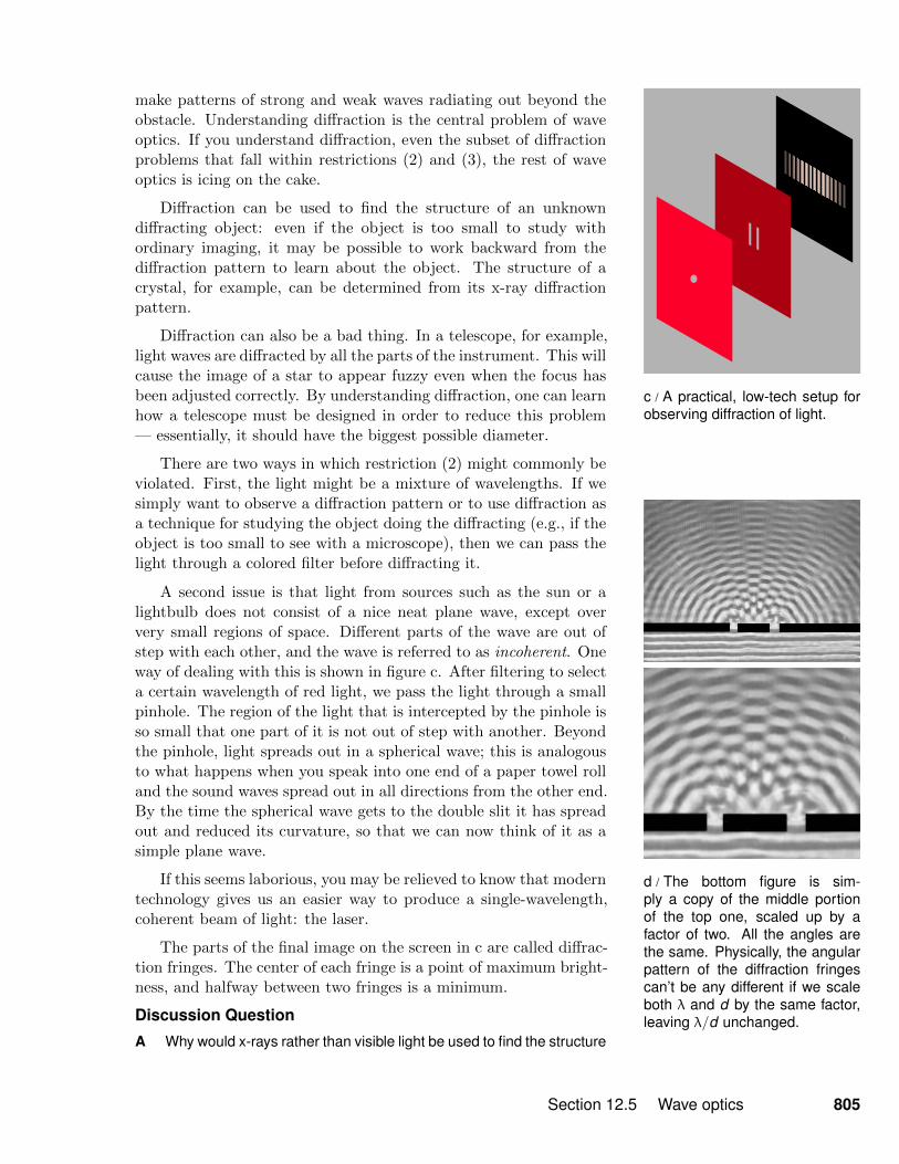


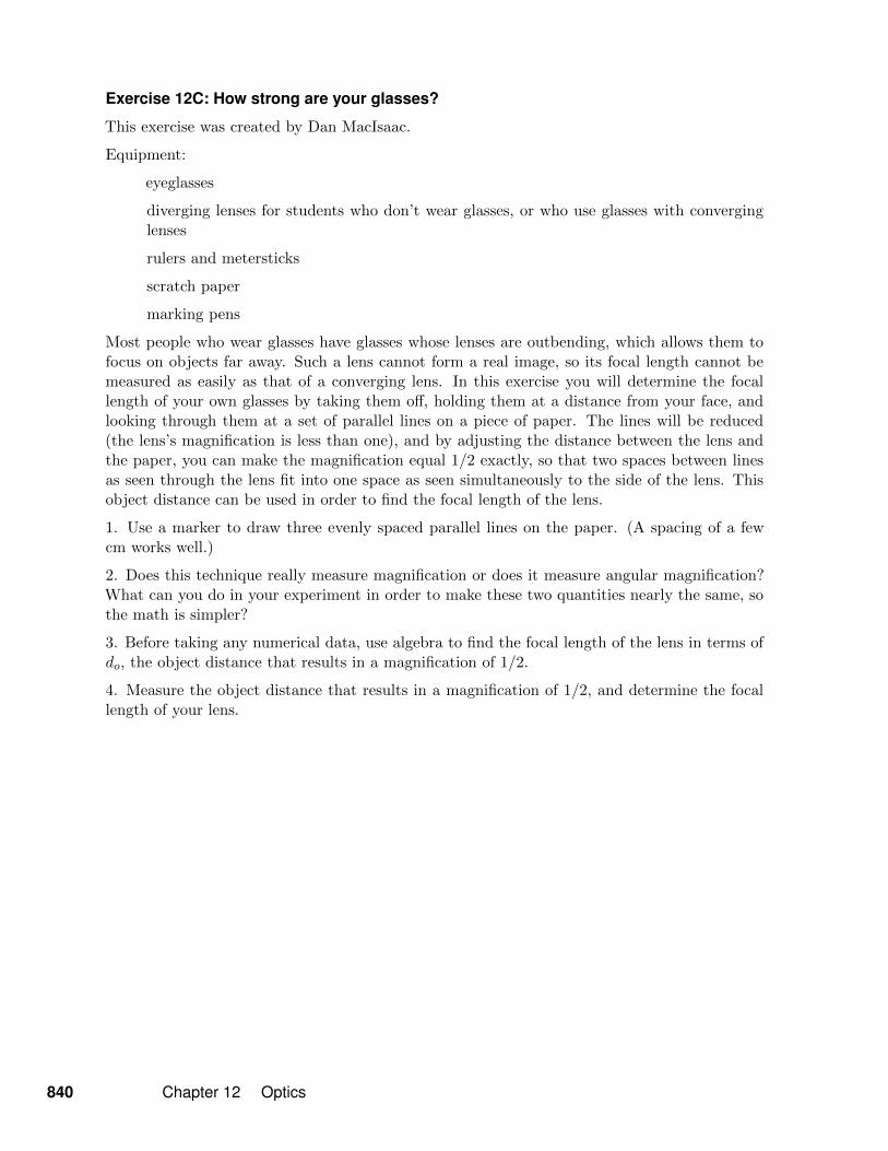


![ROR [20791]](https://static.documents.pub/doc/80x56/563db9ca550346aa9a9feea2/ror-20791.jpg)

