Page 1
Chemical Sciences & Engineering BARC HIGHLIGHTS 49
Uranium Technology and Processes
I N T R O D U C T I O N
Uranium technology is vital to the nuclear energy programme. Given the lean sources of uranium in India, BARC has been concerned with
the development of processes for recovery of uranium from secondary sources and dilute waste streams. The sea water has the lowest
concentration uranium source, but holds enormous quantities of uranium. BARC has taken the first few significant steps in the long
journey towards establishing a economically feasible process for recovery of uranium from sea water. The uranium metal production
process is continually improved to enhance recovery and to handle different grades of feed material, such as, crude UF4 from monazite.
Abatement of pollution of nitrates has been taken up on a mission mode, while modifications to the process have ensured minimisation
of waste. Progress in the novel indigenous process of plasma based hydrogen reduction of UF6 to UF4 is also described in this chapter.
6 . U R A N I U M T E C H N O L O G Y A N D P R O C E S S E S
Page 2
BARC HIGHLIGHTS Chemical Sciences & Engineering50
Uranium Technology and Processes
6.1 URANIUM RECOVERY FROM LOW CONCENTRATE
SOURCES. Application of Liquid Membrane System for
Recovery / Concentration of Uranium from Dilute
Solution
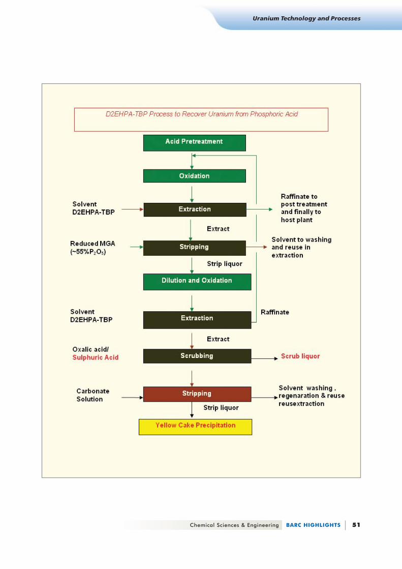
. Development of D2EHPA - TBP Process for
Uranium Recovery from Weak Phosphoric Acid
An innovative dual cycle extraction process has been developed
at laboratory and pilot plant scale for extraction of hexavalent
uranium from 4-6 M phosphoric acid. The process incorporates
selective scrubbing of co-extracted rare earths
in second cycle, followed by two stage
precipitation to yield high purity yellow cake.
The process patent was filed in the US (Patent
ApplicationNo. 09/947,349 dt 7/9/2001)) The
figure (on following page), gives the main steps
of the process.
H. S ingh <hs ingh@barc .govhs ingh@barc .govhs ingh@barc .govhs ingh@barc .govhs ingh@barc .gov. in. in. in. in. in>
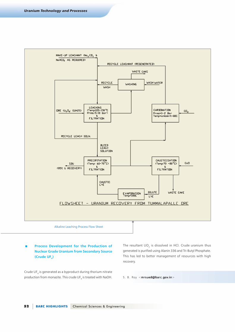
. Technology Demonstration, based
on Alkaline Leaching Process, at
UCIL Jaduguda for Recovery of
Uranium from Tummalapalle Ore
A joint developmental activity has been
undertaken by the Chemical Engineering and
Technology Group, Materials Group, BARC,
Atomic Minerals Directorate and Uranium
Corporation of India Limited, for recovery of uranium from
Tummalapalle ore. The objective is to set up a pilot plant (Capacity-
batch mode-250kg ore/batch; continuous mode-50 kg/hour)
based on alkaline leach process. The pilot plant will incorporate
complete process integration. The operation of the plant will
confirm the laboratory results and generate experimental data
to establish the techno-economic feasibility of the process for
recovery of uranium from Tummalapalle ore. Further, engineering
data, required for the design of production scale plant, will be
collected. Detail engineering work has been completed and the
pilot plant is being installed When commissioned, it will establish
an efficient process for recovery of uranium.
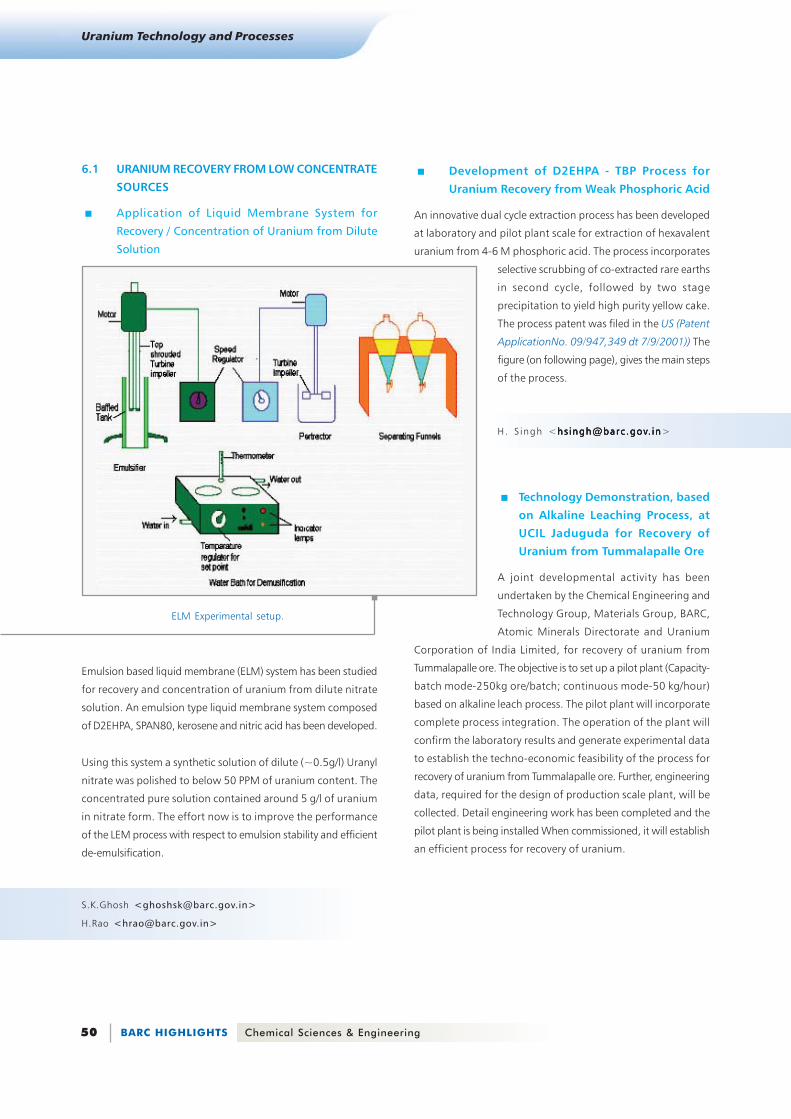
ELM Experimental setup.
Emulsion based liquid membrane (ELM) system has been studied
for recovery and concentration of uranium from dilute nitrate
solution. An emulsion type liquid membrane system composed
of D2EHPA, SPAN80, kerosene and nitric acid has been developed.
Using this system a synthetic solution of dilute (~0.5g/l) Uranyl
nitrate was polished to below 50 PPM of uranium content. The
concentrated pure solution contained around 5 g/l of uranium
in nitrate form. The effort now is to improve the performance
of the LEM process with respect to emulsion stability and efficient
de-emulsification.
S.K.Ghosh <[email protected] >
H.Rao <[email protected] >
Page 3
Chemical Sciences & Engineering BARC HIGHLIGHTS 51
Uranium Technology and Processes
Page 4
BARC HIGHLIGHTS Chemical Sciences & Engineering52
Uranium Technology and Processes
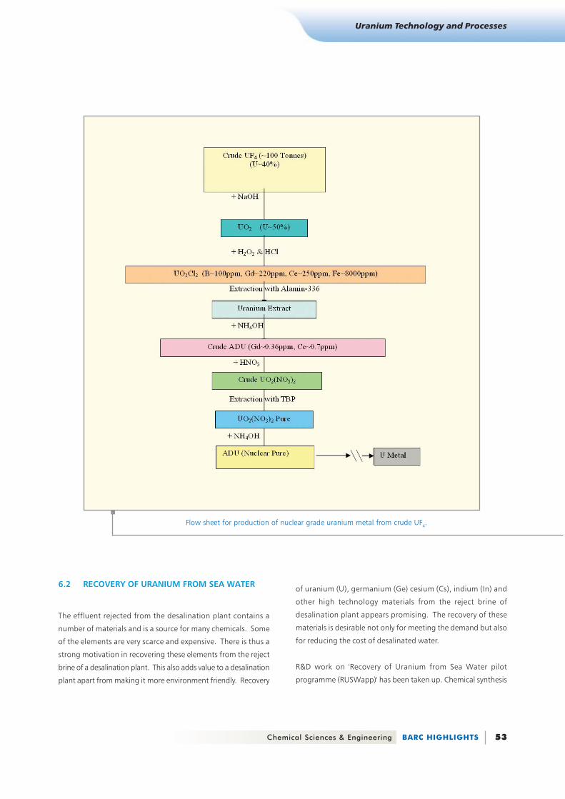
. Process Development for the Production of
Nuclear Grade Uranium from Secondary Source
(Crude UF4)
Crude UF4 is generated as a byproduct during thorium nitrate
production from monazite. This crude UF4 is treated with NaOH.
The resultant UO2 is dissolved in HCl. Crude uranium thus
generated is purified using Alanin 336 and Tri-Butyl Phosphate.
This has led to better management of resources with high
recovery.
S. B. Roy <[email protected] @[email protected] @[email protected] . in. in. in. in. in>
Alkaline Leaching Process Flow Sheet
Page 5
Chemical Sciences & Engineering BARC HIGHLIGHTS 53
Uranium Technology and Processes
Flow sheet for production of nuclear grade uranium metal from crude UF4.
6.2 RECOVERY OF URANIUM FROM SEA WATER
The effluent rejected from the desalination plant contains a
number of materials and is a source for many chemicals. Some
of the elements are very scarce and expensive. There is thus a
strong motivation in recovering these elements from the reject
brine of a desalination plant. This also adds value to a desalination
plant apart from making it more environment friendly. Recovery
of uranium (U), germanium (Ge) cesium (Cs), indium (In) and
other high technology materials from the reject brine of
desalination plant appears promising. The recovery of these
materials is desirable not only for meeting the demand but also
for reducing the cost of desalinated water.
R&D work on 'Recovery of Uranium from Sea Water pilot
programme (RUSWapp)' has been taken up. Chemical synthesis
Page 6
BARC HIGHLIGHTS Chemical Sciences & Engineering54
Uranium Technology and Processes
route and Ionising radiation route were pursued. Ionizing
Radiation route using Electron Beam Irradiation was further
pursued to provide irradiation grafting of ACN on a non-woven
PP Fibre substrate availing the expertise of RTDS. About 130%
grafting was achieved. Conversion of ACN to PAO up to
50-60% of the substrate weight was achieved.
Experimental data were collected for immersion depth,
alkalination optimisation, bio and dirt fouling, tidal wave velocity
A total of about 800 μg of U was collected in 5 campaigns from
CIRUS Jettyhead, about 1.8 mg from TAPS seawater intake and
outfall canals and around 200 μg from Andaman & Nicobar
Islands. The specific collection was found to be from 60 to 160
μg/g of PAO in 12 to 24 days. This can be compared to adsorption-
equilibrium of 1000 μg /g of PAO in 52 days at 25°C in laboratory
condition results as reported by Japanese researchers. It was
observed that vanadium is also getting collected on the adsorbent.
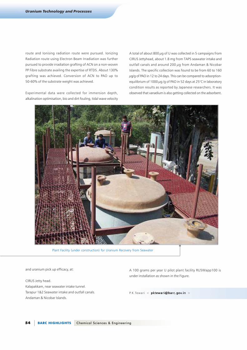
Plant Facility (under construction) for Uranium Recovery from Seawater
A 100 grams per year U pilot plant facility RUSWapp100 is
under installation as shown in the Figure.
P.K.Tewar i < pktewar i@barc .govpktewar i@barc .govpktewar i@barc .govpktewar i@barc .govpktewar i@barc .gov. in. in. in. in. in >
and uranium pick up efficacy, at:
CIRUS Jetty head.
Kalapakkam, near seawater intake tunnel.
Tarapur 1&2 Seawater intake and outfall canals.
Andaman & Nicobar Islands.
Page 7
Chemical Sciences & Engineering BARC HIGHLIGHTS 55
Uranium Technology and Processes
6.3 URANIUM METAL PRODUCTION. Production of 450 Kg Uranium Metal Ingots in
India
. Pelletized Charge Magnesiothermic Reduction
(MTR) for Production of UUUUU metal
Charge pellet was prepared under controlled atmosphere using
hydraulic press. In a MgF2 lined reactor of 5 Kg capacity, pelletized
charge was randomly stacked and fired for completion of reaction.
Pellets for handling could be prepared without compromising
purity of product and recovery. This facility is to be scaled up to
the required plant size
Page 8
BARC HIGHLIGHTS Chemical Sciences & Engineering56
Uranium Technology and Processes
leaching of the slag mass at controlled condition. This has led to
production of high purity metal powder of reproducible quality.
. Study of Uranium Peroxide Precipitation for
Reduction in Nitrate Waste
Studies were carried out with the objective of developing a process
for UO3 without generating nitrogenous liquid waste and
obtaining UO3 of required chemical purity and physical
characteristics, suitable for uranium metal ingot production.
Uranium compound (oxide or diuranate) is dissolved in sulphuric
acid. Uranium is precipitated as UO4 by maintaining stringent
parameters and filtered to get UO4 cake. The product UO4 is
chemically nuclear grade. The effluent generated in this process
is disposable as per MPCB guidelines. Physical characteristics of
the UO4 and the UO3 obtained after calcination are to be of
suitable grade for further conversion to metal ingot.
S. B. Roy <[email protected] >
. Recovery of Uranium from Scrap U-Cu
Cluster Generated during Fuel Fabrication
With the objective of maximising overall recovery in the fuel
production cycle, a process has been developed to selectively
remove copper from U-Cu clusters, and thereby making available
the uranium for fuel fabrication without reprocessing. It involves
preferential leaching of Cu with HNO3 under controlled
conditions. Uranium in the leach liquor (0.6 %) is recovered as
ammonium diuranate by ammonia precipitation. High recovery
of 99.4 % is achieved during solid-liquid separation. Typical batch
size is ~100 Kg.
. Production of Uranium Powder
A process has been developed for production of a specified
grade uranium powder.It involves metallothermic reduction of
UO2. The product uranium powder is recovered by selective
Process flow sheet for production of nuclear grade uranium metal from crude ADU
Page 9
Chemical Sciences & Engineering BARC HIGHLIGHTS 57
Uranium Technology and Processes
6.4 NEW PLASMA BASED PROCESS FOR
CONVERSION FROM UF6 TO UF4
UF6 is the only known compound of Uranium which is highly
volatile at ordinary temperature. UF6 is used as a feed material in
enrichment processes like gas diffusion, gas centrifuge etc. The
enriched UF6 as well as tails of the enrichment plant can not be
stored in cylinder for a longer duration of time because of their
toxic and corrosive nature. Hence they should be converted to
more stable compounds like UF4/U3O8 for storage. Conventionally
UF6 is reduced to UF4 by hydrogen at about 600ºC. Thermal
plasma process offers a clear, faster and advanced technology
for processing waste UF6 without needing any additional chemical
and hence significantly reducing the waste generated.
The segmented arc Plasma Torch
Provision for measurement of gas temperature at various sections
has been done. A 2D axisymmetric simulation for temperature
and velocity mapping has been carried out.
L.M. Gantayet <[email protected] >
A. K. Das <[email protected] >
6.5 POLLUTION ABATEMENT THROUGH
DENITRATION. Recovery of Nitrate Values from Raffinate Stream,
as Concentrated Metal Nitrate and Nitric Acid by
Evaporation and Distillation
Based on the studies conducted on lab scale earlier in Chemical
Engineering Division, a facility has been set up capable of
processing 40-60 litre/hr of dilute nitrate waste stream. The
process consists of filtration, organic removal (TBP) by diluent
wash / ion-exchange, and vapor feed rectification for recovery
of 6- 8 M nitric acid. This facility when, operated with raffinate
stream of uranium refining plant, will generate engineering data
and establish the process on pilot scale. This will also provide a
concentrated nitrate solution suitable for thermal denitration
plant.
S. K. Ghosh <[email protected] >
H. Rao <[email protected] >
Temperature Fields in the torch
A plasma chemical process is currently being developed for
efficient conversion of UF6 to UF4. A special constricted arc
plasma generator has been designed and fabricated at Laser and
Plasma Technology Division to produce argon hydrogen plasma
that exits through a nozzle into a plasma reactor. Additional
hydrogen and UF6 gas will be input in the reactor that has been
designed in three sections namely the inlet and mixing zone,
reaction zone and collection zone.
Page 10
BARC HIGHLIGHTS Chemical Sciences & Engineering58
Uranium Technology and Processes
. Development of Fluidized Bed Thermal
Denitration Technology.
The thermal denitration programme is targeted for processing
both product and waste nitrate streams of nuclear fuel cycle.
Using fluidized bed thermal denitration, streams with high
concentration of nitrate values (> 200 gm/lit) will be denitrated.
The nitrate values will be recovered as nitric acid (for reuse) while
the metal values as oxide for storage or further usage. A bench
scale plant of 5 litres per hour capacity has been commissioned.
The process flow sheet is represented below.
The various sub-systems in the plant are solid handling system,
feed spray system, heat input system, off-gas treatment system.
The plant is under operation for comprehensive development of
the fluidized bed thermal denitration technology.
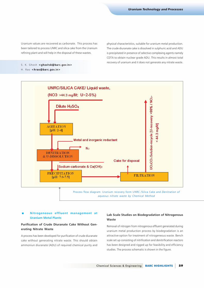
. Chemical Denitration
A uranium recovery from Uranyl nitrate raffinate cake (UNRC)
and silica cake cum denitration process of aqueous waste
containing nitrates, has been developed. Bench scale trial on 1
kg batch of UNRC and silica cake has been carried out. UNRC
and silica cake generally contains 2-5% uranium and 2-10%
nitrate. The process involves leaching of UNRC and silica cake
with dilute sulfuric acid and reduction of nitrate to nitrogen gas
with metallic reductant.
Fluidized bed thermal denitration- Process Flow Sheet
Control room
Fluidized bed reactor
Page 11
Chemical Sciences & Engineering BARC HIGHLIGHTS 59
Uranium Technology and Processes
Uranium values are recovered as carbonate. This process has
been tailored to process UNRC and silica cake from the Uranium
refining plant and will help in the disposal of these wastes.
S . K . Ghosh <ghoshsk@barc .gov<ghoshsk@barc .gov<ghoshsk@barc .gov<ghoshsk@barc .gov<ghoshsk@barc .gov. i n>. in>. in>. in>. in>
H. Rao <hrao@barc .gov<hrao@barc .gov<hrao@barc .gov<hrao@barc .gov<hrao@barc .gov. i n>. in>. in>. in>. in>
. Nitrogeneous effluent management at
Uranium Metal Plants
Purification of Crude Diuranate Cake Without Gen-
erating Nitrate Waste
A process has been developed for purification of crude diuranate
cake without generating nitrate waste. This should obtain
ammoniun diuranate (ADU) of required chemical purity and
physical characteristics, suitable for uranium metal production.
The crude diuranate cake is dissolved in sulphuric acid and ADU
is precipitated in presence of selective complexing agents namely
CDTA to obtain nuclear grade ADU. This results in almost total
recovery of uranium and it does not generate any nitrate waste.
Process flow diagram: Uranium recovery form UNRC /Silica Cake and Denitration of
aqueous nitrate waste by Chemical Method
Lab Scale Studies on Biodegradation of Nitrogenous
Waste
Removal of nitrogen from nitrogenous effluent generated during
uranium metal production process by biodegradation is an
attractive option for treatment of nitrogeneous waste. Bench
scale set up consisting of nitrification and denitrification reactors
has been designed and rigged up for feasibility and efficiency
studies. The process schematic is shown in the figure.
Page 12
BARC HIGHLIGHTS Chemical Sciences & Engineering60
Uranium Technology and Processes
In nitrification reactor more than 90% reduction efficiency has
been consistently achieved with ammoniacal nitrogen feed
concentration up to 450 mg/L. In the denitrification reactor
more than 99% reduction efficiency has been consistently
achieved with nitrate nitrogen feed concentration up to
1450 mg/L. Cascading of two reactors and scale up of the
reactors will be tried.
Acclimatization of bacteria for higher concentration nitrogenous
effluents more specifically for ammoniacal effluent is a challenge
to be met.
Raffinate Recycle
Recycle of raffinate will utilise the nitric acid for plant recycle.
This will also result in reduction of nitrogen bearing effluent.
Laboratory scale trials have been conducted under a controlled
temperature with conditioned feed. Nitric acid concentration
was increased from about 1.5 N to 6 N which is suitable for
plant recycle. The proces is being scaled up.
Development of Process for Decontamination of
Byproduct Hydrofluoric Acid
A process was developed in Uranium Extraction Division with the
objective of obtaining zero fluoride effluent discharge and
thereby by reusing / recycling the treated effluent. Concentrated
aqueous HF was treated to remove radioactivity. After clarification
it was suitable for industrial utilization. Dilute aqueous HF solution
was treated to fix the fluoride as insoluble salt and recycle the
filtrate for process requirement. These processes reduce the load
on effluent management to a considerable extent.
S. B . Roy <mrsued@barc .gov<mrsued@barc .gov<mrsued@barc .gov<mrsued@barc .gov<mrsued@barc .gov. in>. in>. in>. in>. in>
Schematic Flow sheet for Bio-Treatment of Nitrogenous Effluents