WWW.WAMBAMFENCE.COM 1 ASSEMBLY INSTRUCTIONS VG26300 VG26300 ASSEMBLY INSTRUCTIONS 60 MIN Approximate assembly me Want to see a video on how to assemble this product? Scan the QR code 6’ WIDE PRIVACY VINYL GATE (ADJUSTABLE WIDTH) WWW.WAMBAMFENCE.COM VER. 032221
Transcript
WWW.WAMBAMFENCE.COM 1
ASSEMBLY INSTRUCTIONS VG26300
VG26300
ASSEMBLY INSTRUCTIONS
60 MINApproximate assembly time
Want to see a video on how to assemble this product?
Scan the QR code
6’ WIDE PRIVACY VINYL GATE
(ADJUSTABLE WIDTH)
WWW.WAMBAMFENCE.COM VER. 032221
WWW.WAMBAMFENCE.COM2
ASSEMBLY INSTRUCTIONSVG26300
k Check the inside of the larger pieces in your box for other materials packed inside.
k When assembling components, place on a non-abrasive surface (i.e. shipping box) to avoid scratching.
k We recommend an area approximately 5’x 8’ for unobstructed assembling.
k You should not need to use excessive force when assembling components.
VISIT OUR WEBSITE FIRST, SO WE CAN HELP YOU RIGHT AWAY!Although great care has been taken to ensure proper packaging and handling of this product, occasionally problems occur. If you discover any missing, damaged or defective parts, please visit our website to order replacement parts. If you experience any further trouble with your product, please contact our customer care department.
Customer service agents are available to take calls weekdays from 9am-5pm EST. If you call outside of business hours, please leave a voicemail.
To help you quickly and accurately, please have reference item number VG26300 and the specific part name which can be found on page 5. It is helpful if you can provide the batch lot which is a stamped number inside the box.
Please give us a call at 704-892-5222 / 877-778-5733.If you are having problems with the assembly or installation of this product, we are happy to assist you with the process.
If for some reason you need to return this product, please allow us to help resolve your issues first. If you still decide to return the product, you will need to initiate the return from the company you originally purchased from.
GENERAL INFORMATION
MISSING OR DAMAGED PARTS?
NEED ASSEMBLY HELP?
NEED TO RETURN?
IMPORTANT
WWW.WAMBAMFENCE.COM 3
ASSEMBLY INSTRUCTIONS VG26300
1. Read over fence instructions first.
2. Pre-Assemble the gate frame.
3. Install your gate posts before your fence posts.
4. Do not hang your gate system off a single non-supported post.
Your gate and fence will work better together if you first take the time to read and understand your fence.
Please do not screw the gate frame together until you have temporarily assembled the gate frame. In other words, do a dry run first. This will ensure:
Your fence panels will be more forgiving for a custom fit than your gate. Position and install your gate posts before you do anything else.
Your gate will perform better and last longer if your hinge post is connected to a panel of fence that is connected to another post. This way, the weight strain will be trans-ferred onto two posts versus just one. Installing fence panels on both sides of your gate is ideal in all situations. If this is not possible because of space restrictions, please contact us for alternative solutions.
It’s easier to troubleshoot when things are not screwed together. After you assemble your gate correctly, please disassemble as necessary, and use the 1¼” self-drilling stainless steel screws to permanently assemble the gate.
1. That you have everything necessary to complete the gate.2. That you will have assembled the gate frame in the correct order.3. All of the pieces fit and function properly.4. The gate height and width are similar to the measurements shown on page one.
GENERAL INFORMATION
WWW.WAMBAMFENCE.COM4
ASSEMBLY INSTRUCTIONSVG26300
DETAILED PRODUCT DIMENSIONS AND SPECIFICATIONS
70.00
72.00
54.65
7.80
7.80
7.80 56.40 7.80
3.50
74.0079.00
72.00
2.002.00
42.00
48.00
72.00
WWW.WAMBAMFENCE.COM 5
ASSEMBLY INSTRUCTIONS VG26300
IA
D
B
E F
G
H
C
J
K
L
M
N
O
Hinge (2)
Latch Catch (1)
Latch Finger (1)
1¼” White Self-Drilling Stainless Steel Screw (24)
1¼” Black Self-Drilling Stainless Steel Screw (24)
2” Black Self-Drilling Stainless Steel Screw (14)
2¾” Gate Tension Pin (1)
STEP 1: LAY OUT MATERIALS
Corner Bracket (4) Metal Post Stabilizer (1)
Gate Brace w/ Fasteners (1)
Vertical Stile (2) 1½" x 3½" x 63"
Gate Jig (1) 1½" x 3½" x 82¼"
Gate Rail (2) 1½" x 3½" x 571¾"
Privacy Board 1 (5) ½" x 12" x 66½"
Privacy Board 2 (1) ½" x 10⅝" x 66½"
WWW.WAMBAMFENCE.COM6
ASSEMBLY INSTRUCTIONSVG26300
STEP 2: INSTALL GATE JIG, POST ANCHORS, AND POSTS
STEP 2.1 STEP 2.2
Identify the location of your gate. Dig a trench 60” long x 6” wide x 5½” deep.
Identify the location of the Metal Post Stabilizer (B) and pound it into the ground. Temporarily place the anchor positioner into the metal post stabilizer and determine position.
Place Gate Jig (G) over the metal post stabilizer.
Place the anchor positioners into gate jig. The pegs on the bottom of the anchor positioners will insert into both the gate jig and the metal post stabilizer.
Backfill excavated dirt over gate jig. Pound your post anchors into place. See fence instructions if necessary for more information on how to install anchors. Adjust the leveling donuts and install the posts.
Note: Metal post stabilizer to be used only on hinge post.
5½”
B
G
STEP 2.3
STEP 2.5 STEP 2.6
STEP 2.4
WWW.WAMBAMFENCE.COM 7
ASSEMBLY INSTRUCTIONS VG26300
STEP 2.7
Make sure to fasten the fence panels before attaching the gate.
STEP 3: ASSEMBLE THE GATE FRAME BOTTOM AND SIDES
STEP 3.1
Insert a Gate Rail (H) until it bottoms out inside Corner Bracket (A).
Insert the gate rail until it bottoms out inside the opposite corner bracket.
Insert Vertical Stiles (F) untill they hit the gate rail.
Insert fully to this point.
Insert fully to this point.
Inse
rt fu
lly to
this
poin
t.
Inse
rt fu
lly to
this
poin
t.A
F
H
STEP 3.2 STEP 3.3
WWW.WAMBAMFENCE.COM8
ASSEMBLY INSTRUCTIONSVG26300
STEP 4: INSERT PRIVACY BOARDS
STEP 4.1 STEP 4.2
Insert the tongue and groove of Privacy Board 2 (E) tightly into the vertical stile.
Privacy Boards 1 (D) should bottom out inside the gate rail.
E
D
STEP 5: ASSEMBLE GATE FRAME TOP
STEP 5.1 STEP 5.2
Insert the other gate rail all the way until they bottom out inside the corner brackets.
Slide the top gate rail and corner brackets over the privacy boards and vertical stiles.
WWW.WAMBAMFENCE.COM 9
ASSEMBLY INSTRUCTIONS VG26300
STEP 6: FASTEN GATE BRACKETS
STEP 7: ATTACH GATE HARDWARE
STEP 6.1
STEP 7.1 STEP 7.2
STEP 6.2
To ensure your gate is square, the corner to-corner measurement must be the same, andthe width of the gate should be 48”.
Fasten the Hinges (J) onto the brackets with (8) 1¼” Black Self-Drilling Stainless Steel Screws (N).
Fasten the Latch Finger (L) onto the arch bracket with (6) 1¼” black self-drilling stainless screws.
Fasten together using (16) 2” Black Self-Drilling Stainless Steel Screws (O).
O
48”
JN
L
WWW.WAMBAMFENCE.COM10
ASSEMBLY INSTRUCTIONSVG26300
STEP 8: ASSEMBLE AND FASTEN GATE BRACE
STEP 8.1
STEP 8.2
Assemble Gate Brace (C) by sliding the larger square tube over the smaller square tube. Align holes and install included hardware.
Double check that the gate is square, and screw with (4) 1¼” White Self-Drilling Stainless Steel Screws (M) the gate brace into place as illustrated.
C
M
WWW.WAMBAMFENCE.COM 11
ASSEMBLY INSTRUCTIONS VG26300
STEP 9: ALIGN GATE AND SECURE HINGES TO POST
Align gate to horizontal fence rails.
STEP 9.1
Note: Both fence & gate horizontal rail spacing can be adjusted freely to lower heights.
Fasten hinges to posts as illustrated.
STEP 9.2A
Note: See next page on how to position screws on the post side of the hinge.
WWW.WAMBAMFENCE.COM12
ASSEMBLY INSTRUCTIONSVG26300
STEP 9.2B
STEP 9.2C STEP 9.2D STEP 9.2E
How to position the screws on the post side of the hinge: Using a ⅛” drill bit, pre-drill the holes for hinge screws as illustrated. Angle your drill slightly as illustrated.
Fasten (3) hinge screws through the drilled holes Repeat steps 7.2B and 7.2C for the second hinge.
Swing the gate open and pre-drill four more holes for the hinge screws as illustrated.
Fasten (4) hinge screws through the drilled holes. Repeat steps 7.2D and 7.2E for the second hinge.
Top ViewNote: Angle your drill topierce into angled portionof post as illustrated.
WWW.WAMBAMFENCE.COM 13
ASSEMBLY INSTRUCTIONS VG26300
STEP 10.1 STEP 10.2
Fasten gate hinges. Check for level, fit and function to latching post.
Hinges can be adjusted moderately to bring gate into level alignment with post.
Latch is designed for left and right hand applications. Temporarily remove the spring, bolt and reverse paddle portion as necessary.Note: Adjust the spring tension in gates
as necessary. Use the included 4” Gate Tension Pin (I).
STEP 10: LEVEL GATE AND ADJUST HINGES
STEP 10.3 STEP 10.4
Note: To set the tension on the gate hinge, insert the 4” gate tension pin into one of the holes on hinge and rotate it to release tension on the gate hinge to remove pin.
WWW.WAMBAMFENCE.COM14
ASSEMBLY INSTRUCTIONSVG26300
STEP 11: INSTALL LATCH CATCH
STEP 11.1
Align and fasten the Latch Catch (K) to fit and function with the gate finger.
Congratulations! You did it! Go grab a beverage of your choice, admire your handiwork, and show us what you got by entering our annual photo contest!
K
WWW.WAMBAMFENCE.COM 15
ASSEMBLY INSTRUCTIONS VG26300
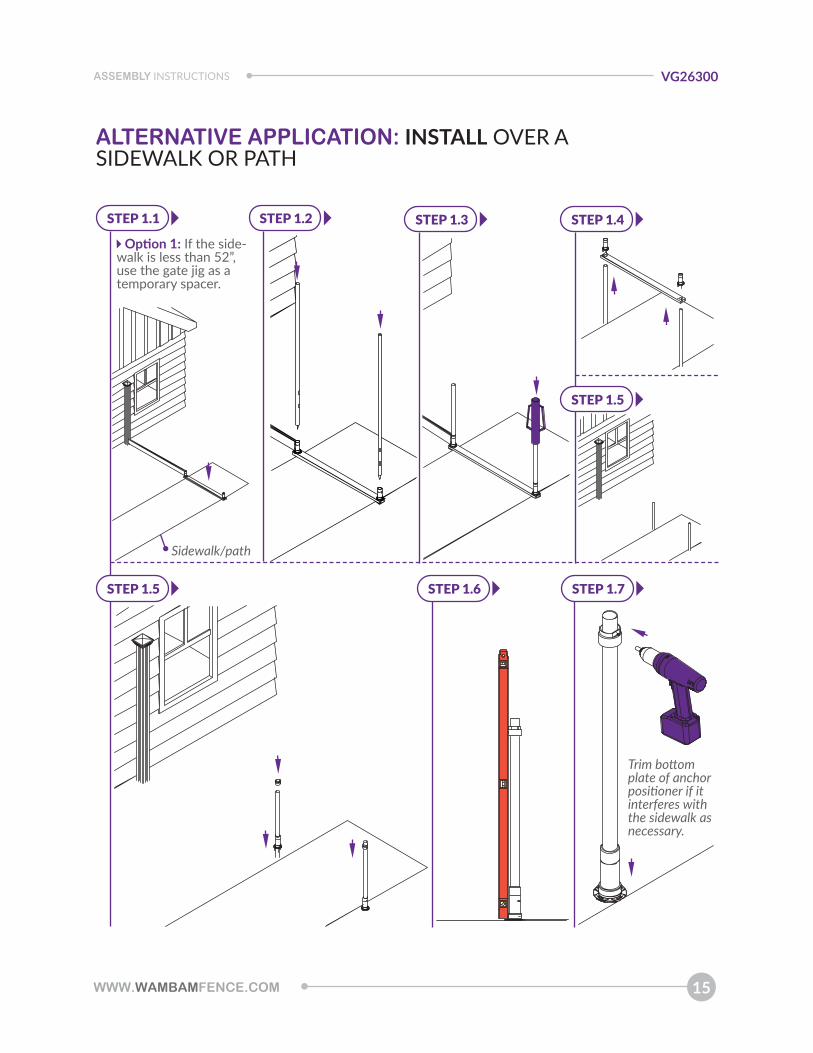
ALTERNATIVE APPLICATION: INSTALL OVER A SIDEWALK OR PATH
Option 1: If the side-walk is less than 52”, use the gate jig as a temporary spacer.
Sidewalk/path
Trim bottom plate of anchor positioner if it interferes with the sidewalk as necessary.
STEP 1.1 STEP 1.2 STEP 1.3
STEP 1.6 STEP 1.7
STEP 1.4
STEP 1.5
STEP 1.5
WWW.WAMBAMFENCE.COM16
ASSEMBLY INSTRUCTIONSVG26300
Option 2: If the sidewalk is wider than 52”, use Surface Mounts (purchase separately).
STEP 2.1 STEP 2.2 STEP 2.3
ALTERNATIVE APPLICATION: INSTALL OVER A SIDEWALK OR PATH