EC-SMART-VUE EC-SMART-VUE Topics: 1 – Model Comparison & Features 2 – Smart-Vue Sub-Network 3 – Scenes, Values & Conditions Topics: 1 – Model Comparison & Features 2 – Smart-Vue Sub-Network 3 – Scenes, Values & Conditions 1 EC-SMART-VUE 2 2 – Smart-Vue Subnetwork When you’ve completed this presentation on EC-gfxProgram Basics, click on the “QUIZ” button below to take a short quiz. Then click the brown “NEXT MODULE” arrow below to advance to the next e-module – Module 3: Distech Controllers. Click to review Instructions > EST: 60:00 3 – Scenes, Values & Conditions 1 – Model Comparison & Features CONTINUE 4 – Labwork
Transcript
EC-SMART-VUEEC-SMART-VUE
Topics:
1 – Model Comparison & Features
2 – Smart-Vue Sub-Network
3 – Scenes, Values & Conditions
Topics:
1 – Model Comparison & Features
2 – Smart-Vue Sub-Network
3 – Scenes, Values & Conditions
1
EC-SMART-VUE
2
2 – Smart-Vue Subnetwork
When you’ve completed this presentation on EC-gfxProgram Basics, click on the “QUIZ” button below to take a short quiz. Then click the brown “NEXT MODULE” arrow below to advance to the next e-module – Module 3: Distech Controllers.
Click to review Instructions >
EST: 60:00
3 – Scenes, Values & Conditions
1 – Model Comparison & Features
CONTINUE
4 – Labwork
EC-Smart-Vue
Navigation Instructions
3
Select any button on the main menu to navigate to the topic of choice.
When done with that topic, look for the red “BACK TO MENU” arrow to return to this menu.
BACK TO MENU
At any time during a topic, you may click on the blue “BACK TO MENU” arrow at the bottom to return to the main menu.
BACK TO MENU
EC-Smart-Vue
Navigation Instructions
4
MORE INFORMATION LINKS: Select these links whenever prompted to view examples and additional info.
You will see instructions in this box regarding what to click and what you will see.
Hysteresis
Limit / Linear
ADDITIONAL MENU LINKS: Select these links whenever prompted to obtain more information on a specific topic.
BACK TO TOOLBOX
ADDITIONAL NAVIGATION LINKS: Select these links to navigate from sub-topics back up to the topic level.
QUIZ LINKS: Select these links to test your knowledge at the end of each module.
NEXT MODULE LINKS: Select this link when you’ve completed the current module and wish to advance to the next module.
NEXT MODULE
In some cases, there may be
semi-transparent green highlighted areas like this that are hyperlinked.
EC-Smart-Vue
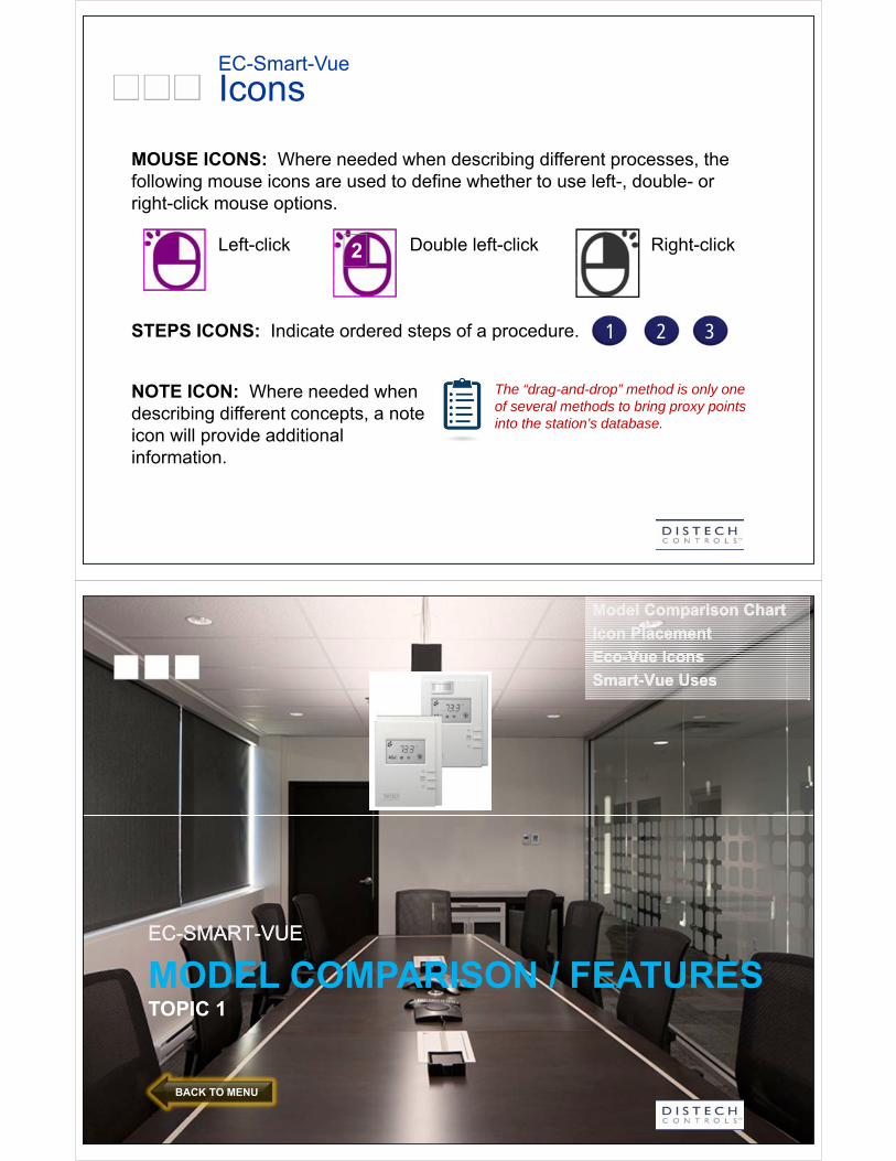
Icons
Right-click2
MOUSE ICONS: Where needed when describing different processes, the following mouse icons are used to define whether to use left-, double- or right-click mouse options.
Double left-clickLeft-click
STEPS ICONS: Indicate ordered steps of a procedure. 1 2 3
The “drag-and-drop” method is only one of several methods to bring proxy points into the station’s database.
NOTE ICON: Where needed when describing different concepts, a note icon will provide additional information.
MODEL COMPARISON / FEATURESTOPIC 1
EC-SMART-VUEEC-SMART-VUE
BACK TO MENU
Model Comparison Chart
Icon Placement
Eco-Vue Icons
Smart-Vue Uses
Model Comparison Chart
Icon Placement
Eco-Vue Icons
Smart-Vue Uses
EC-Smart-Vue 4-in-1 Series
7BACK TO MENU
EC-Smart-Vue – Model Comparison
8
EC-Smart-Vue interfaces with the ECY/ECB/ECL series controller and is a 4-in-1 sensor (CHM model):
Temperature Relative humidity Motion CO2
It has a customizable LCD readout and graphically indicates energy consumption using the ECO-Vue leaf pattern.
Temperature
Relative Humidity H)
Motion (M)
Carbon dioxide (C)
Scenes: rolling, quick edit, menu
ECO-Vue leaf: energy consumption
Advanced menu options
EC-Smart-Vue – Icon Placement
9
EC-Smart-Vue LCD screen with ICONS
Configurable through EC-gfxProgram
UnitsUnits
OccupancyOccupancyFanFan
ClockClock
BACK TO MENU
EC-Smart-Vue – Icon Placement
10BACK TO MENU
EC-Smart-Vue – ECO-Vue Icon
11BACK TO MENU
EC-Smart-Vue Uses
12
MAC Address
Baud Rate
Flow Balance
VAV Box Configuration
Device ID
Subnet
Configurable through EC-gfxProgram > >
Commissioning Tool > > > >
Scenes: rolling, quick edit, menu
Advanced menu optionsAdvanced menu options
Customizable Icons
BACK TO MENU
EC-Smart-Vue: A Commissioning Tool
13
EC-Smart-Vue can also be used as a commissioning tool to:
Set the MAC Address, Baud Rate, Subnet or Device ID for BACnet ECB-series and ECB-VAV-series controllers
Flow balance VAV controllers
Configure VAV box configurations for VAV controller pre-loaded applications
MAC Address
Baud Rate
Flow Balance
VAV Box Configuration
Device ID
Subnet
BACK TO MENU
EC-Smart-Vue: A Commissioning Tool
EC-Smart-Vue as a Commissioning tool for all ECB controllers. Once connected to an ECB controller, the EC-Smart-Vue can be used to perform commissioning tasks:
14
Setting ECB controller’s MAC address: Set all DIP switch to 0 (apply to ECB-203 and over)
Use the Gen Conf menu to access the MAC ADDRESS
Setting ECB controller’s Baud rate: The default Baud rate for all ECB controllers is set to AUTO
(recommended)
The Bus Master (EC-BOS) should be the reference Baud rate (if present)
Otherwise, set the Baud rate on one controller on the bus by using the Gen Conf menu to access the BAUD RATE
Accessing the BACnet MS/TP LAN: The EC-Smart-Vue Sub-Network cable also brings the
BACnet MS/TP Network to the sensor for installation and maintenance purposes
The LAN is made available at the communications jack (stereo jack)
BACK TO MENU
SMART-VUE SUBNETWORKTOPIC 2
EC-SMART-VUEEC-SMART-VUE
BACK TO MENU
Overview
Description
Subnet ID
Overview
Description
Subnet ID
Sub-Network Overview
16BACK TO MENU
Sub-Network Description
The Sub-Network on the ECL and ECB lines of controllers is used to communicate with communicating peripherals made by Distech Controls like:
– EC-Smart-Vue
– ECx I/O modules
17
The Sub-Network works with RS-485 transceivers, that makes the wiring and addressing methods very similar to the BACnet MS/TP bus, but it is NOT part of the BACnet Network.
Sub-Network: Subnet ID
Setting the EC-Smart-Vue Subnet ID (Subnet MAC Address) The default Subnet ID for an EC-Smart-Vue is set to 1
Keep default Subnet ID of 1 if there is only one EC-Smart-Vue connected to the controller
If you have more then 1 EC-Smart-Vue on the Sub-Network, change the Subnet ID on each one to a unique number as follows:
18
1. Connect the EC-Smart-Vue to the controller. Wait for the Bell icon and the number 1 to flash on the display
2. Press and hold the Menu button for 5 seconds to enter the password menu. 10000 is shown on the display
3. Use the down button to set the number to 9995 (this is the default password)
4. Use the Menu button to select SUBNET ID. The current controller’s Subnet ID is shown
5. Use the up and down buttons to set the controller’s Subnet ID
6. Press the Menu button once to validate and save your selection
7. Press and hold the Menu button for 5 seconds to exit the configuration menu.
BACK TO MENU
SCENES, VALUES & CONDITIONSTOPIC 3
EC-SMART-VUEEC-SMART-VUE
BACK TO MENU
Main Rolling Scenes
Quick Edit Scenes
Menu Scenes
Local & Global Values
Conditions
Enumerations
Icons
Main Rolling Scenes
Quick Edit Scenes
Menu Scenes
Local & Global Values
Conditions
Enumerations
Icons
EC-Smart-Vue: Main Rolling Scenes
20
Standard Scenes Custom Scenes
96 Scenes are available.
Display Values and Information
Some Standard Scenes are already configured
Display Space Temp
Display Relative Humidity
BACK TO MENU
EC-Smart-Vue: Quick Edit/Menu Scenes
21
Quick Edit Scenes: Scene that is displayed when an
arrow key is pressed
Used to Edit a value (typically the Temperature setpoint)
Menu Scenes: Scenes that are displayed when
the menu button is pressed
Advance to the next Scene each time the menu button is pressed
Used to Edit or View many other values
BACK TO MENU
EC-Smart-Vue: Advanced Menu Scenes
22
Scenes that are displayed when the menu button is held for 5 sec
Must provide the default password of 9995.
The first one is the password Scene
Some Standard Scenes already exist:
Edit Subnet ID
Edit MAC Address
Edit Baud Rate
Display Hardware Info
Calibrate Space Temp
Adjust Contrast
BACK TO MENU
EC-Smart-Vue: Values
23
Used to Store data available to and from the EC-Smart-Vue:
30 Local Values
Number and name of Values identical across all the EC-Smart-Vues on the controller
Values within the Local Values are unique for each EC-Smart-Vue
70 Global Values
Names and values are shared across all the EC-Smart-Vues
BACK TO MENU
EC-Smart-Vue: Conditions
24
Used to Hide/Show Scenes
15 Conditions
Number and name of registers identical across all the EC-Smart-Vues on the controller
Values within the conditions are unique for each EC-Smart-Vue
BACK TO MENU
EC-Smart-Vue: Enumerations
25
Used to select options in the Select Enumeration scenes
User can select the numerical Start Value of the enumeration
Total of 127 Strings available for enumerations
Each string up to 16 characters
Texts displayed in the text section of a scene are using Strings out of the 127
Optimization done if the same text is used more than once
BACK TO MENU
EC-Smart-Vue: Icons Selection
26
Used to display any Icon in any Scene
Set by an Icon Value selection
Unit Icons are also use for conversions
BACK TO MENU
EC-Smart-Vue Icons Selection
27BACK TO MENU
EC-Smart-Vue: Communication
28
Local ValuesSmartVue1
ConditionsSmartVue1
Local ValuesSmartVue2
ConditionsSmartVue2
Local ValuesSmartVue3
ConditionsSmartVue3
Global Values
2-way communication
Local and Global Values
Local Conditions
Local Values
Occupied Cool Setpoints
Occupied Heat Setpoints
…
Global Values
Minimum Airflow Setpoint
VAV application code
…
BACK TO MENU
EC-Smart-Vue: Conclusion
Fully customizable
Templates are available within the gfxApplications code library
Integrators should always start from a template when configuring the EC-Smart-Vue
96 Scenes are available for display and edit
All Scenes are identical for each EC-Smart-Vue connected to the same controllers.
Conditions and local/global values are used to display different information on different EC-Smart-Vues (e.g., remove a Scene for one or more EC-Smart-Vues)
Integrators should never try to modify the preloaded ECB Series code. If another sequence of operation is needed, start from the gfxApplications library.
29BACK TO MENU
LABWORKTOPIC 4
EC-SMART-VUEEC-SMART-VUE
BACK TO MENU
Main Rolling Scenes
Quick Edit Scenes
Menu Scenes
Main Rolling Scenes
Quick Edit Scenes
Menu Scenes
31
Lab 15: Configuring the EC-Smart-Vue
LAB 15 – 80 minConfiguring the EC-Smart-Vue
OVERVIEW
LAB 15 – 80 minConfiguring the EC-Smart-Vue
OVERVIEW
BACK TO MENU
80:00
Lab 15: Configuring the EC-Smart-Vue
LAB 15A: 5 minConnect the EC-Smart-Vue and Add a Com Sensor blockConnect the EC-Smart-Vue to the ECL-650 via CAT-5.
Replace the Space Temp HWI block with a Com Sensor block.
LAB 15A: 5 minConnect the EC-Smart-Vue and Add a Com Sensor blockConnect the EC-Smart-Vue to the ECL-650 via CAT-5.
Replace the Space Temp HWI block with a Com Sensor block.
LAB 15B: 5 minConfigure the Com Sensor BlockConfigure the Com Sensor block for the model type, time format, and backlight.
LAB 15B: 5 minConfigure the Com Sensor BlockConfigure the Com Sensor block for the model type, time format, and backlight.
LAB 15C: 5 minValidate/Modify a Main Rolling SceneAdd text to an existing main rolling scene and validate that it displays on the LCD screen.
LAB 15C: 5 minValidate/Modify a Main Rolling SceneAdd text to an existing main rolling scene and validate that it displays on the LCD screen.
BACK TO MENU
Lab 15: Configuring the EC-Smart-Vue
LAB 15D: 10 minAdd a stock Main Rolling SceneRelative Humidity, CO2
LAB 15D: 10 minAdd a stock Main Rolling SceneRelative Humidity, CO2
LAB 15E: 10 minAdd a custom Main Rolling SceneOutdoor Air Temp – add as a Global Value – so it can be displayed on multiple EC-Smart-Vue controllers on a network
LAB 15E: 10 minAdd a custom Main Rolling SceneOutdoor Air Temp – add as a Global Value – so it can be displayed on multiple EC-Smart-Vue controllers on a network
LAB 15F: 10 minAdd a Quick Edit SceneSetpoint – add as a Local Value – specific to one EC-Smart-Vue.
LAB 15F: 10 minAdd a Quick Edit SceneSetpoint – add as a Local Value – specific to one EC-Smart-Vue.
BACK TO MENU
Lab 15: Configuring the EC-Smart-Vue
LAB 15G: 20 minAdd a Menu SceneOccupancy – as an Icon Enumeration – person inside/outside of a house. Add as a Local value.
Create additional logic to generate a pulse into the Min On Time block.
LAB 15G: 20 minAdd a Menu SceneOccupancy – as an Icon Enumeration – person inside/outside of a house. Add as a Local value.
Create additional logic to generate a pulse into the Min On Time block.
LAB 15H: 15 minOptional: Add a Menu Scene
Fan Speed – as an Icon Enumeration – using Fan icon.
LAB 15H: 15 minOptional: Add a Menu Scene
Fan Speed – as an Icon Enumeration – using Fan icon.
BACK TO MENU
Lab 15: Configuring the EC-Smart-Vue
LAB 15A: 5 minConnect the EC-Smart-Vue and Add a Com Sensor blockConnect the EC-Smart-Vue to the ECL-650 via CAT-5. Replace the
Space Temp Hardware Input block with a Com Sensor block.
LAB 15A: 5 minConnect the EC-Smart-Vue and Add a Com Sensor blockConnect the EC-Smart-Vue to the ECL-650 via CAT-5. Replace the
Space Temp Hardware Input block with a Com Sensor block.
BACK TO MENU BACK TO SECTIONS
Lab 15: Configuring the EC-Smart-Vue
BACK TO MENU BACK TO SECTIONS
LAB 15B: 5 minConfigure the Com Sensor BlockConfigure the Com Sensor block for the model type, time format, and
backlight.
LAB 15B: 5 minConfigure the Com Sensor BlockConfigure the Com Sensor block for the model type, time format, and
backlight.
Lab 15: Configuring the EC-Smart-Vue
BACK TO MENU BACK TO SECTIONS
LAB 15C: 5 minValidate/Modify a Main Rolling SceneAdd text to an existing main rolling scene and validate that it displays
on the LCD screen.
LAB 15C: 5 minValidate/Modify a Main Rolling SceneAdd text to an existing main rolling scene and validate that it displays
on the LCD screen.
Lab 15: Configuring the EC-Smart-Vue
BACK TO MENU BACK TO SECTIONS
LAB 15D: 10 minAdd a stock Main Rolling SceneRelative Humidity, CO2
LAB 15D: 10 minAdd a stock Main Rolling SceneRelative Humidity, CO2
Lab 15: Configuring the EC-Smart-Vue
BACK TO MENU BACK TO SECTIONS
LAB 15E: 10 minAdd a custom Main Rolling SceneOutdoor Air Temp – add as a Global Value – so it can be displayed on multiple EC-Smart-Vue controllers on a network
LAB 15E: 10 minAdd a custom Main Rolling SceneOutdoor Air Temp – add as a Global Value – so it can be displayed on multiple EC-Smart-Vue controllers on a network
Lab 15: Configuring the EC-Smart-Vue
LAB 15F: 10 minAdd a Quick Edit SceneSetpoint – add as a Local Value – specific to one EC-Smart-Vue.
LAB 15F: 10 minAdd a Quick Edit SceneSetpoint – add as a Local Value – specific to one EC-Smart-Vue.
BACK TO MENU BACK TO SECTIONS
LAB 15G: 20 minAdd a Menu SceneOccupancy – as an Icon Enumeration – person inside/outside of a house. Add as a Local value. Create additional logic to generate a pulse into the Min On Time block.
LAB 15G: 20 minAdd a Menu SceneOccupancy – as an Icon Enumeration – person inside/outside of a house. Add as a Local value. Create additional logic to generate a pulse into the Min On Time block.
Lab 15: Configuring the EC-Smart-Vue
BACK TO MENU BACK TO SECTIONS
15G – Add a Menu Scene
LAB 15G: 20 minAdd a Menu SceneOccupancy – as an Icon Enumeration – person inside/outside of a house. Add as a Local value. Create additional logic to generate a pulse into the Min On Time block.
LAB 15G: 20 minAdd a Menu SceneOccupancy – as an Icon Enumeration – person inside/outside of a house. Add as a Local value. Create additional logic to generate a pulse into the Min On Time block.
BACK TO MENU BACK TO SECTIONS
Smart-Vue: Conclusion
Fully customizable
Templates are available within the gfxApplications code library
Integrators should always start from a template when configuring the EC-Smart-Vue
96 Scenes are available for display and edit
All Scenes are identical for each EC-Smart-Vue connected to the same controllers.
Conditions and local/global values are used to display different information on different EC-Smart-Vues (e.g., remove a Scene for one or more EC-Smart-Vues)
Integrators should never try to modify the preloaded ECB Series code. If another sequence of operation is needed, start from the gfxApplications library.
43BACK TO MENU
BACK TO EC-SMART-VUE
MENU(CLICK HERE)
It’s Quiz Time
It’s time to review what you’ve learned.
Click the QUIZ button to begin.If you wish to review first, click the REVIEW button below.