DO NOT INSTALL OR OPERATE, READ THIS FIRST! TRASH COMPACTORS AND BALERS Vertical Baler (6030HD) Installation, Operating, and Service Manual ACE Equipment Company W9112 Cherry Road Antigo, Wisconsin 54409 (715) 627 – 2400 aceequipmentcompany.com Revision Number: 2 Date Modified: July 15, 2015
Transcript
DO NOT INSTALL OR OPERATE, READ THIS FIRST!
TRASH COMPACTORS AND BALERS
Vertical Baler (6030HD)
Installation, Operating, and Service Manual
ACE Equipment Company W9112 Cherry Road
Antigo, Wisconsin 54409 (715) -‐ 627 – 2400
aceequipmentcompany.com Revision Number: 2
Date Modified: July 15, 2015
1
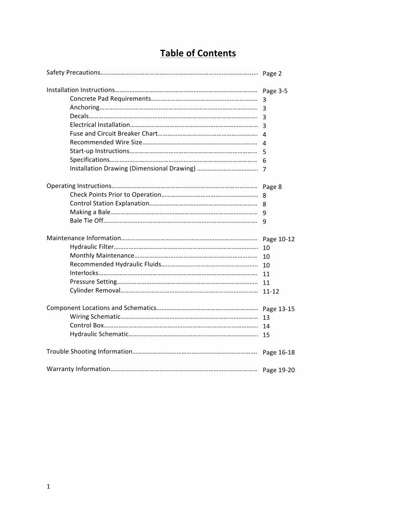
Table of Contents
Safety Precautions………………………………………………………………………………...….. Installation Instructions……………………………………………………………………………….. Concrete Pad Requirements……………………………………………………………………… Anchoring…………………………………………………………………………………….. Decals…………………………………………………………………………………………… Electrical Installation………………………………………………………………………………… Fuse and Circuit Breaker Chart…………………………………………………………………… Recommended Wire Size…………………………………………………………………
For quick reference should service be needed, please fill out the following information. Always keep this manual in a safe readily accessible location. Model Number________________________________________ Serial Number _________________________________________ Service Company Name___________________________________ Telephone Number ______________________________________ For operating instruction call (715) -‐ 627 -‐ 2400, ask for technical service.
Safety Precautions The following is a list of warnings, some of which will be repeated in locations throughout this manual. Read these warnings carefully to insure proper operation of this equipment. Warning: Do not operate until operation instructions are understood. Danger: Never place any part of body inside bale chamber. Caution: Employer should allow only authorized and trained personnel to operate this
equipment. Federal regulation prohibits operation by persons under 18 years of age. Turn off, remove key after use.
Warning: Periodic maintenance is required and is your responsibility. Lock Out/Tag Out: The purpose of this procedure is to ensure that the equipment is isolated
from its energy sources and rendered inoperative prior to service or maintenance.
Responsibilities for Lock Out/Tag Out The standard requires employers to establish and energy program which includes:
1) Documented energy control procedures 2) An employee training program 3) Periodic inspections of the use of the procedure
Compliance with the development and accordance of Lock Out/Tag Out procedure shall be the responsibility of the employer. Procedure for Lock Out/Tag Out
1) The suggested procedure to comply with this standard is outlined as follows: 2) Remove the system key 3) Lock out the main power disconnect per OSHA requirements. 4) Tag out all other controls or energy sources not capable of being locked out. Every
person affected should know and understand all lock out tags. The above is an outline of the OSHA standard for locking and tagging out equipment. The employer is responsible for following the latest OSHA guidelines.
3
Installation Instructions
Read this manual before making installation. Study the jobsite and installation requirements carefully to be certain all necessary safeguards and/or safety devices are provided to protect all personnel and equipment during installation and as a completed system. Special attention is direct to the extract from American National Standards Institute. ACE Equipment Company does not assume responsibility for installation procedure of this equipment. Conformance to applicable local, state, and federal laws concerning installation rests with the customer. Concrete Pad
1) Pad should be minimum 3,000 PSI concrete, steel reinforced, 6” thick. It is preferred that pad be flush with surrounding area.
2) Concrete pad should be positioned to allow access to panel box between baler and building walls. Working clearance for panel box must comply with state and local building cost. Allow enough space from bale chamber for bale handling vehicle. See installation drawing 6.
Anchoring
Anchor baler to floor using anchor plates on sides of baler base. Four 1” diameter anchor bolts required.
Decals
Installation of the baler is not complete until and inspection warning decals is complete. Decals should be clearly visible, legible, securely applied and in the proper location. For decal description and location see page 8.
Warning
Before and during making any electrical connections and/or maintenance and/or testing, be sure the disconnect/power source switch is Lock Out/Tag Out.
Electrical Connection
Before connecting power to the baler check line voltage with a voltmeter. Also check wiring in the panel box. If the baler is not wired to the proper voltage call the manufacture.
Motor VAC To 100 Feet To 200 Feet To 300 Feet 10 HP. 208 8 6 4
230 8 6 4 460 10 8 6
Single Phase
Motor VAC To 100 Feet To 200 Feet To 300 Feet 10 HP. 208 8 6 4
230 4 3 2
The above charts is a recommendation, ACE Equipment Company does not assume responsibility. Check local, state codes for wiring.
5
Start-‐Up Instruction Warning: Before proceeding remove ¾” plug from top of reservoir and install filler breather
cap. Filler breather is shipped inside panel box. Danger: Do not climb on sides of baler. Use a ladder while performing the following procedure.
Warning: Parts of platen may extend above top of baler when platen is fully raised.
1) Check Hydraulic Fluid Level Refer to maintenance chart for recommendations on hydraulic oil. Note: Platen should be in the fullest up position when checking fluid level. Reservoir should be filled to ¾ level on sight gauge. Hydraulic system pressure has been factory set and entire unit operated prior to shipment.
2) Check Motor Rotation
Caution: Make sure personnel and material are clear of bale chamber. Danger: Never place any part of body inside bale chamber or in area between platen and top of baler. Danger: Stay clear of moving parts while performing this operation
a) Close bale chamber and feed gate b) Turn disconnect on c) Check motor rotation by watching hub coupling through slot in pump-‐to-‐motor adapter. Have someone turn on the key switch and press the auto cycle button for one second then immediately press the stop button.
Caution: If pump rotates backwards, stop immediately. Pump will be damaged if run in reverse for even short periods of time. Turn off and lock out/tag out baler, have certified electrician change the phase rotation
3) Check Interlocks
The baler is equipped with an electrical interlock which prevents the use of the “auto cycle” function when the feed gate is up or when the door is open. If the “auto cycle” starts the baler when the feed fate is up or the main door is open, discontinue immediately lock out/tag out until the repairs have been made.
• Press “auto cycle” the platen should make a complete cycle down and up. When the platen is in its fully raised position the feed gate should automatically open and the motor should immediately shut down.
6
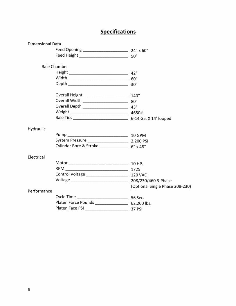
Specifications
Dimensional Data Feed Opening ____________________ Feed Height __________________________
System Pressure ________________________ Cylinder Bore & Stroke _________________
Electrical
Motor ________________________________ RPM __________________________________ Control Voltage __________________________ Voltage ______________________________
Performance
Cycle Time _____________________________ Platen Force Pounds _____________________ Platen Face PSI ________________________
24” x 60” 50” 42” 60” 30” 140” 80” 43” 4650# 6-‐14 Ga. X 14’ looped 10 GPM 2,200 PSI 6” x 48” 10 HP. 1725 120 VAC 208/230/460 3-‐Phase (Optional Single Phase 208-‐230) 56 Sec. 62,200 lbs. 37 PSI
7
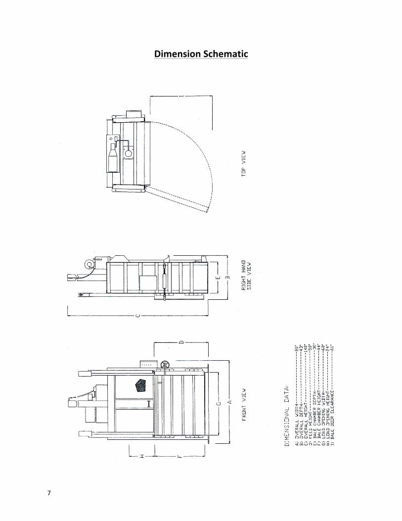
Dimension Schematic
8
Operating Instructions
Warning: Do not operate until operating instructions are understood. Caution: Allow only authorized and trained personnel to operate
the baler. Baler is equipped with a keyed on/off switch. The key should be in the possession of only trained authorized personnel.
Warning: Federal regulation prohibits operation of this equipment by persons
under 18 years of age. Check Points Prior to Operation:
1) Never place any part of body inside bale chamber. 2) Clear all personnel away from baler before starting unit. 3) Be certain the turnbuckle is fully locked in place on bald door before starting baler. 4) Be sure the feed gate is closed.
Function of Control
1) On/Off (Keyed Selector Switch) Turning this switch to the on position activates the other controls on the control station. The baler cannot be operated unless the key switch is in the on position. The purpose of this switch is to allow only authorized and trained personnel to operate the baler. The key should be removed from the switch when the baler is not in use. The key should stay in the possession of responsible and trained personnel.
2) Auto Cycle (Green Push Button with Light)
The Auto Cycle Button will light once the feed gate is fully closed and the door is completely closed. The Auto Cycle Button can be used only when the feed gate and the bale door are closed and the key switch is in the on position. Once the Auto Cycle Button is depressed the platen will move to the fully down position and back to the fully raised position. One complete compaction cycle.
3) Emergency Stop (Red Mushroom Head Push-‐button)
Depressing the emergency button will stop the movement of the platen at any point in the cycle.
4) Manual Up (White Push-‐Button) This push-‐button will only start the baler with the key switch on the “on” position. Depressing the up button will raise the platen with the feed gate and bale door open or closed. It is normally used during bale ejection. It can also be used to interrupt the automatic cycle and raise the platen should it become necessary. The manual up push-‐button is a deadman control i.e. the baler will stop as soon as it is released.
5) Bale Made
When the bale shifts from the down position to the up position and the arrows align this is the bale made indicator
9
Baling Process
Making a Bale: Danger:
1) Never Place any part of body inside bale chamber. 2) Stand clear while baler is in operation. 3) Feed gate opens automatically. Do not attempt to open feed gate manually.
4) Press the start button. 5) Place large, flat piece of material flat on floor. 6) Feed material into baler.
Note: Do not attempt to over fill feed chamber by forcing in material with feed gate. This can cause gate release malfunction and may damage baler.
6) Pull handle to close feed gate. 7) Depress “auto cycle” button. Baler will make one complete down and up cycle. Feed gate will
automatically open. 8) Repeat steps 3 through 5 until the platen shift from down to up and the bale made light
comes on.
Bale Tie Off 1) Insert large, flat piece of material (cardboard) across top of bale. 2) Close feed gate. 3) Press “start” button the platen will go down and stop on compressed material. 4) Clear area in front of door.
a. CAUTION: Clear all personnel from front of baler before proceeding with steps 5
through 13.
5) With all personnel clear of bale door, release bale door latch from side. 6) Caution: WEAR SAFETY GLASSES AND LEATHER GLOVES DURING THIS OPERATION. Tie off bale
by inserting bale ties through the slots in platen, loop end first. Feed wire through until it comes through slot in back of baler, and then feed wire through slot in floor of baler until it comes out the front side. Tie off each wire before inserting the next wire. Bale ties should be tightened, hand tight, allowing for bale expansion.
7) Place the bale ejector handle (J-‐Hook)on the bar of the platen. 8) Standing at side, make sure all personnel are clear of baler. Press the “start” button. 9) Hold “start” button until bale ejects, release “start” button. 10) Remove the bale after ejected. 11) Insert large, flat piece of material (cardboard) across baler floor. 12) Close bale door. Close feed gate. Return J-‐Hook to holder on back of baler. 13) Bale sequence is ready to be repeated.
10
Maintenance
Warning: Before and during making any electrical connection and/or maintenance and/or testing, be sure the disconnect switch is “off” and pad locked, Locked Out/Tag Out. place warning tag on disconnect “WARNING-‐DO NOT ENERGIZE WITHOUT PERMISSION OF ________________________.”
Hydraulic Filter
1) Hydraulic filter should be cleaned after one month of operation then at regular intervals of six months.
2) Filter may be cleaned by manually removing filter which is inside reservoir. 3) Care should be taken in cleaning filter to insure the element is not torn. Clean with soft
brush and standard solvent. 4) Replace filter after cleaning. Pump noise and “crackle” sound is most often caused by
air entering pump suction line. Tightening suction hose connections will usually eliminate such problems.
Monthly Maintenance
1) The hoses should be checked periodically to insure that they do not become worn before being replaced. All fighting’s should be kept tight and no leaks allowed in the hydraulic systems without immediate corrective measures.
2) Each month the baler should be lubricated and any material which has accumulated behind the platen should be removed.
a) Grease door hinges b) Oil gate track c) Oil mechanical door lock
3) Check for any obvious unsafe conditions, such as worn electrical lines or operator obstructions in baler area.
4) Check oil level in hydraulic reservoir by sight gauge. 5) Check interlocks for proper operation. 6) Check functional operation of all standard controls (push-‐button, key switch, lights,
etc.). See section on operation of controls. 7) Check hydraulic cylinder, cylinder pin and bolts for signs of leakage, wear or fatigue. 8) Check all decals and replace if damaged.
This machine is equipped with a solid state output proximity switch. To check the switch turn the key switch to the “on” position. When the bale door is closed the light on the back of the proximity switch should be on. When the bale door is open the light should be off. If further verification is needed a volt meter (120 vac) may be connected to first orange terminal and second orange terminal in the control panel box. The meter should read “0” volts with the bale door open and 120 volts with the gate closed. In no instance should the baler operate in “auto Cycle” with the feed fate up or the bale door open. Note: If the interlock in not working properly disconnect (lock out/tag out) and lock out power unit repairs can be made.
Pressure Setting
1) Turn off and lock out/tag out power. 2) Manually shift solenoid in both directions to relive pressure. Do not climb on side of baler
or enter bale chamber. Use a ladder. 1) Remove plug from ½” 90 degree elbow in sub-‐plate. Install pressure gauge. 2) Loosen nut on relief valve and back out adjustment screw a few turns. 3) Have someone hold the manual down button. Turn the adjustment screw clockwise until
the pressure gauge indicates 2,000 PSI. 4) Tighten locknut.
Cylinder Removal
1) Lock out/tag out power supply 2) Block up platen to take pressure off cylinder pin and to prevent it from falling when pin is
removed. Warning: Be sure platen is securely held up before proceeding.
3) Remove bolts from cylinder pin. 4) Remove platen from baler. 5) Turn on power and press “manual up” push-‐button until cylinder is fully retracted. 6) Lock out/tag out power supply 7) Relieve hydraulic pressure by manually depressing solenoid valve (both sides). 8) Note: Remove hose fittings slowly, remove both hoses from cylinder.
Warning: Be sure hydraulic cylinder is securely supported before proceeding. 9) With hydraulic cylinder supported by another means loosen the ¾” grade 8 cylinder bolts and
grade 8 locknuts. 10) Remove cylinder
12
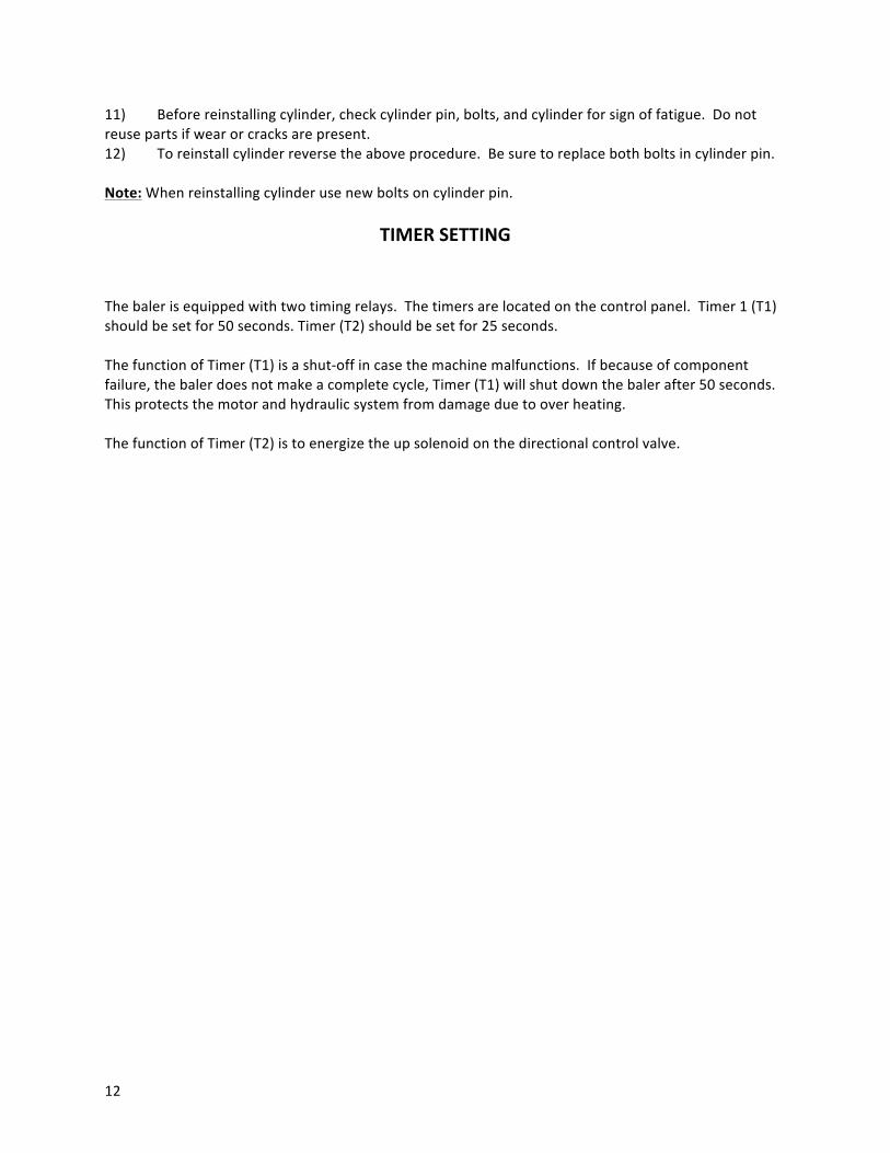
11) Before reinstalling cylinder, check cylinder pin, bolts, and cylinder for sign of fatigue. Do not reuse parts if wear or cracks are present. 12) To reinstall cylinder reverse the above procedure. Be sure to replace both bolts in cylinder pin. Note: When reinstalling cylinder use new bolts on cylinder pin.
TIMER SETTING
The baler is equipped with two timing relays. The timers are located on the control panel. Timer 1 (T1) should be set for 50 seconds. Timer (T2) should be set for 25 seconds. The function of Timer (T1) is a shut-‐off in case the machine malfunctions. If because of component failure, the baler does not make a complete cycle, Timer (T1) will shut down the baler after 50 seconds. This protects the motor and hydraulic system from damage due to over heating. The function of Timer (T2) is to energize the up solenoid on the directional control valve.
13
Wiring Schematic
14
Control Box
15
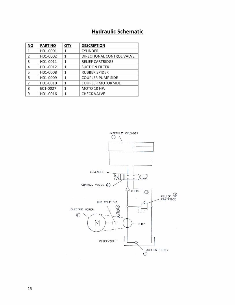
Hydraulic Schematic
NO PART NO QTY DESCRIPTION 1 H01-‐0001 1 CYLINDER 2 H01-‐0002 1 DIRECTIONAL CONTROL VALVE 3 H01-‐0011 1 RELIEF CARTRIDGE 4 H01-‐0012 1 SUCTION FILTER 5 H01-‐0008 1 RUBBER SPIDER 6 H01-‐0009 1 COUPLER PUMP SIDE 7 H01-‐0010 1 COUPLER MOTOR SIDE 8 E01-‐0027 1 MOTO 10 HP. 9 H01-‐0016 1 CHECK VALVE
16
Trouble Shooting
Problem Cause Solution Unit will not start No electrical power Check main disconnect
Replace fuses or reset breakers No electrical power to control
panel Check primary and secondary sides of transformer
Check control fuses Check stop button Check start button to be sure contacts
closed when depressed. No electrical power to motor Check all interlocks
Unit will not continue running when start button is released
Relay or contacts are in-‐operative
Check relay coil, contacts, and wiring
Motor starter or contacts in-‐operative
Check motor starter coil, contacts, and wiring
Secondary contact on start button is in-‐operative
Check contact to be sure it is operating properly
Check wiring Motor runs but platen does
not move normally Insufficient oil in reservoir Fill reservoir with oil
Low relief pressure Check relief pressure (refer to maintenance information section)
Clean orifice in relief valve and reset pressure.
Check “O” rings on relief valve for damage or leakage
Oil leakage in cylinder hose Check cylinder for bypassing Replace seal kit, inspect rod and
cylinder tube for scoring or kicks Replace cylinder Defective pump Replace pump Low voltage Check voltage Pump may be driven in the
wrong direction or rotation Stop immediately to prevent seizure. Check direction of drive rotation (proper rotation direction is indicated by arrow on motor)
Shaft broken or shaft key sheared
Visually inspect motor and pump shaft and hub couplings for damage. Replace if necessary.
(More problems and solutions on next page for “motor runs but platen…”)
17
Intake pipe from reservoir blocked or oil viscosity too
heavy to prime
Drain system. Add clean fluid of proper viscosity and specifications. Filter as recommended. Check system filter for cleanliness.
Intake air leaks (foam in oil or sounds like gravel in pump)
Check intake connections. Tighten securely.
Unit will not reserve Check wiring Solenoid valves is in operative Check coil and wiring Reverse button in-‐operative Check reverse button contacts
Pump makes noise-‐sounds like gravel
Partly clogged intake strainer or restricted intake pipe
Pump must receive intake fluid freely or cavitation results. Drain systems, clean intake pipe and clean or replace strainer
Defective Bearing Replace pump Air leak at pump in take pipe
joints Tighten joints as required
Excessive heat Continuous running When over 140°F or hot in comparison with circuit lines pump should be shut down immediately. Before restarting insure that fluid cooling capacity is adequate to remove system generated heat.
High ambient temperature in relation to oil temperature
Use low viscosity oil
Excessive system leakage Check system for bypassing or leaks Rapid wear Abrasive matter in the
hydraulic oil being circulated through pump
Clean or replace filter
Replace oil with factory recommendation
Viscosity of oil to low at working conditions
Reduce pressures to factory specifications
Air recirculation causing pump noise
Tighten all fittings
18
Erratic operation Valve sticking or binding Disassemble and clean as necessary Viscosity of oil to high, low oil Change oil to factory recommended
viscosity Air in system Check for leaks, tighten fittings Low voltage Check primary and secondary sides of
transformer for correct voltage. Proximity interlock
malfunction Check interlock, see interlock section
Overloads trip frequently Check for correct voltage incoming power
Check fuses or breakers at disconnect Check heater elements be sure they are
tight Check wiring from starter to motor to
make sure all connections are tight Check motor leads to be sure all
connections are tight Note: Excessive overload tripping and/or motor or coil failures may occur if voltages surges or voltage drops are frequent in your area. This circumstance can be remedied by the installation of phase protectors which drops power to motor if surges are present.
19
Ace Equipment Company W9112 Cherry Road Antigo, WI 54409 P: 715-‐627-‐2400 F: 715-‐627-‐2402
Warranty Policy and Procedure Compactor -‐ Container -‐ Baler Warranty ACE Equipment Company (herein referred to as ACE) warrants each new equipment to be free from defects in material and workmanship under normal use and service. ACE obligation under this warranty for a period of 180 days labor and 360 days parts is limited to replacement of any defective part or material. During such period, this warranty excludes any obligation by ACE for the cost of labor. Transportation or any other cost arising out of such replacements in excess of its standard warranty reimbursement program. Normal use is defined as intermittent operation, one eight-‐hour shift per day, and five days per week. This warranty shall not apply to any equipment, which has been subject to misuse, negligence, alteration or accident. Ace neither assumes nor authorizes anyone to assume for it any other obligation or liability in connection with such equipment. This warranty excludes any obligation by ACE for loss of product, downtime, or any other incidental or consequential damage incurred at any time. This warranty is the only warranty applicable to compactors, containers, and balers manufactured by ACE and is expressly in lieu of all other warranties, expressed or implied, including any implied warranty of merchant or fitness for a particular purpose. Replacement parts are subject to a 30-‐day warranty and are specifically excluded from the standard warranty reimbursement program. Customer Responsibility It is the responsibility of ACE’s customer to install the equipment in conformity with ANSI Z245.1 as well as any applicable codes and regulations. Important: Standard furnished with each compactor installation. Operating and Service Manual, American National Standards Institute Manual, electrical schematic specifically for that unit, and a Warranty Card.
1. ACE’s customer must train authorized operators in safe methods and use of equipment system. 2. The manuals should be retained for future reference and use. 3. The warranty card must be filled out completely and distributed as marked on the card. ACE’s copy must be
forwarded to ACE in order for the unit to qualify for ACE’s warranty program. 4. In the event of failure of component of the product, the customer must contact ACE’s service and warranty manager
providing him, at the time, with a description of the problem, the model and serial number of the product. 5. Important: No claims will be accepted for normal pre or post-‐delivery inspection, lubrication, or adjustments. All
units are inspected and adjusted at the time of manufacture, but the shipping process can loosen fittings and possibly change adjustments. The time involved in the pre or post-‐delivery inspection and adjustments must be part of the installation charge to the owner.
When ACE’s Service manager is advised of service problem presumed to be covered under ACE’s Warranty, the following actions will occur.
1. Parts felt necessary to return the unit to service will be sent to ACE’s customer. The customer will be invoiced for these parts and will be responsible for any freight charges. A statement on the face of the invoice will read Enclosed Warranty Authorization Form NO _______
2. The Warranty Authorization From will be mailed to the Customer. This is too completed by the Customer, and copies
distributed as follows: once copy for the customer file, one copy to be attached to the failed parts.
20
3. The failed parts and WAF form must be returned to Ace within 30 days from the date of failure in order to be considered for warranty replacement.
4. Upon receipt of the part it will be examined by the service and warranty manager, and if it I determined by him to be defective, the original invoice for the replacement parts and the transportation costs (bus, air, courier excluded) will be credited to the customer’s account. This will be limited to the flat rate schedule. The current labor rate is $25.00 per hour.
5. In cases where no flat rate hours are prescribed or the claim shall exceed the flat rate, the customer shall contact the service and warranty manager with an estimate of hours required. Upon approval of this estimate, a “Warranty Authorization Form” will be issued. If it is discovered after repair has begun, that additional work is required and will exceed the original estimate by more than 10% it will be necessary to contact the service manager for approval. Any hours in excess of “Flat Rate Schedule” will be rejected unless a “Warranty Authorization Form” covering additional hours was issued. In addition, any claim received for not listed in the “Flat Rate Schedule” will be rejected unless a “Warranty Authorization Form” has been assigned for this unlisted labor expenditure. No credit will be allowed for labor hours spent in inspection or diagnosis of equipment problems. In cases of failure of equipment which will require repair by welding, re-‐welding, and/or fabrication of additional steel, weldment material, the customer shall again be required to obtain prior approval of method, procedure, and “Warranty Authorization Form Number” from service manager to ensure that:
a. The correct method of repair as prescribed by Ace is followed, and b. Prior agreement is reached as to amount of allowance, which will be credited for the work.
Failure to comply with this procedure will result in rejection of warranty claim and void warranty. 6. Travel time (man and truck) will be allowed on the basis of:
First 25 miles $12.50 To 100 miles $10.00 per 25 miles Over 100 miles $7.50 per 25 miles All mileage is to the nearest 25 miles traveled. Mileage is limited to a maximum of 500 round trip miles.
7. No claims will be allowed for the loss of hydraulic oil except in cases where failure of component clearly indicated the loss of a major portion of the oil in the system. The allowance for oil shall not exceed $2.50 per US gallon. Ace is not responsible for oil clean up, contamination of any kind, or any damage caused by an oil spill.
8. No allowance whatsoever will be made for replacement components, which our inspection subsequently shows not to be defective.
WARRANTY AND SERVICE ON MOTORS If the motor fails, and the equipment is under warranty, have the equipment checked out by and electrician or service man. If there is no problem with fuses or wiring, the motor should be taken to the nearest authorized motor warranty shop, (if you do not have a listing of authorized motor warranty shops, call Ace to determine the locations of the shops in your area). The motor shop will inspect the motor and determine whether it is factory defective. If the motor failed due to defects in material or workmanship, the motor shop will repair or replace the motor at the motor manufacture’s expense. If the motor failure was not caused by defective factory material or workmanship, it will be repaired only if the customer agrees to pay for the expense. Ace Equipment Company will not absorb the cost for pick-‐up or delivery service to service centers on defective motors. Removal and reinstallation covered in the standard warranty policy. SAFETY NOTICE Proper maintenance and repair are essential to the safe, reliable operation of Ace’s products. Service and maintenance procedures recommended by Ace are described in the service manual and are effective for performing service operations. Some of these service operation may require the use of special tools or devices especially designed for the purpose. These tools or devices should be used when and as recommended. These operation instructions are not intended as a substitute for training and experience in proper use and safety procedures in operation this equipment. Anyone who uses service procedures or tools which are not recommended by Ace assumes all risk to persons, equipment, and property. CAUTION Only factory original replacement parts or equivalent should be used to insure safe and proper operation of equipment.