616 IEEE JOURNAL ON EMERGING AND SELECTED TOPICS IN CIRCUITS AND SYSTEMS, VOL. 2, NO. 3, SEPTEMBER 2012
A Hybrid Architecture for CompressiveSensing 3-D CT Reconstruction
Jianwen Chen, Senior Member, IEEE, Jason Cong, Fellow, IEEE, Luminita A. Vese, John Villasenor,Ming Yan, and Yi Zou
Abstract—The radiation dose associated with computerized to-mography (CT) is significant. Compressive sensing (CS) methodsprovide mathematical approaches to reduce the radiation expo-sure without sacrificing reconstructed image quality. However,the computational requirements of these algorithms is muchhigher than conventional image reconstruction approaches suchas filtered back projection (FBP). This paper describes a newcompressive sensing 3-D image reconstruction algorithm basedon expectation maximization and total variation, termed EM+TV,and also introduces a promising hybrid architecture implementa-tion for this algorithm involving the combination of a CPU, GPU,and FPGA. An FPGA is used to speed up the major computationkernel (EM), and a GPU is used to accelerate the TV operations.The performance results indicate that this approach provideslower energy consumption and better reconstruction quality,and illustrates an example of the advantages that can be realizedthrough domain-specific computing.
C OMPUTERIZED tomography (CT) plays a critical rolein modern medicine. However, the radiation associated
with CT is significant, and researchers are exploring variousapproaches to reduce the radiation. Traditionally, image recon-struction requires that the number of samples (measurements orobservations) be dictated purely by Nyquist limits. However,methods such as compressive sensing that exploit object spar-sity can enable CT imaging with less data and therefore lessradiation exposure, without sacrificing image quality.Conventionally, the Feldkamp–Davis–Kress (FDK) algo-
rithm has been used for 3-D cone-beam CT image reconstruc-tion, and it is widely employed in the machines used in clinicalsettings. The computation kernel of the FDK algorithm is called
Manuscript received March 01, 2012; revised August 19, 2012; acceptedSeptember 12, 2012. Date of publication October 23, 2012; date of currentversion December 05, 2012. This work was supported by the Center for Do-main-Specific Computing (CDSC) under the NSF Expeditions in ComputingAward CCF-0926127. This paper was recommended by Guest Editor D. Allstot.J. Chen, J. Cong, and Y. Zou are with the Department of Computer Sci-
of California, Los Angeles, CA 90095 USA (e-mail: [email protected];[email protected]).J. Villasenor is with the Department of Electrical Engineering, University of
California, Los Angeles, CA 90095 USA (e-mail: [email protected]).Color versions of one or more of the figures in this paper are available online
at http://ieeexplore.ieee.org.Digital Object Identifier 10.1109/JETCAS.2012.2221530
filtered back projection (FBP). Generally, FBP is used for 2-Dimages in association with parallel beam CT [1]. Iterative re-construction has also been proposed [2], [3] to reconstruct 2-Dand 3-D images from the projections of an object. An iterativeframework can be used in many applications, including com-puterized tomography (CT), positron emission tomography,and magnetic resonance imaging. The main advantages ofiterative reconstruction over FBP are reduced sensitivity tonoise and increased data collection flexibility [4]. For example,the data can be collected over any set of lines, the projectionsdo not have to be distributed uniformly, and the reconstructioncan also be performed when projections are available for alimited set of angles.Various iterative reconstruction/compressive sensing al-
gorithms have been proposed with different objectives orregularization terms. However, many of these algorithms,including expectation maximization (EM) [5] and simulta-neous algebraic reconstruction technique (SART) [6], share acommon underlying computational approach that includes aforward ray tracing step (forward projection) and a backwardray tracing step (backward projection).In the present paper, we focus on a recent compressive sensing
algorithm (EM+TV) that combines the expectation maximiza-tion (EM) method using Poisson noise with the total variation(TV) regularization. The only precondition of EM+TV algo-rithm is that the reconstructed image cannot have an excessivetotal-variation. For CT images, this precondition is true and theEM+TV algorithm can be applied. The effectiveness of thiscompressive sensing algorithm has been well documented [7].The EM+TV method gives superior results to those obtained
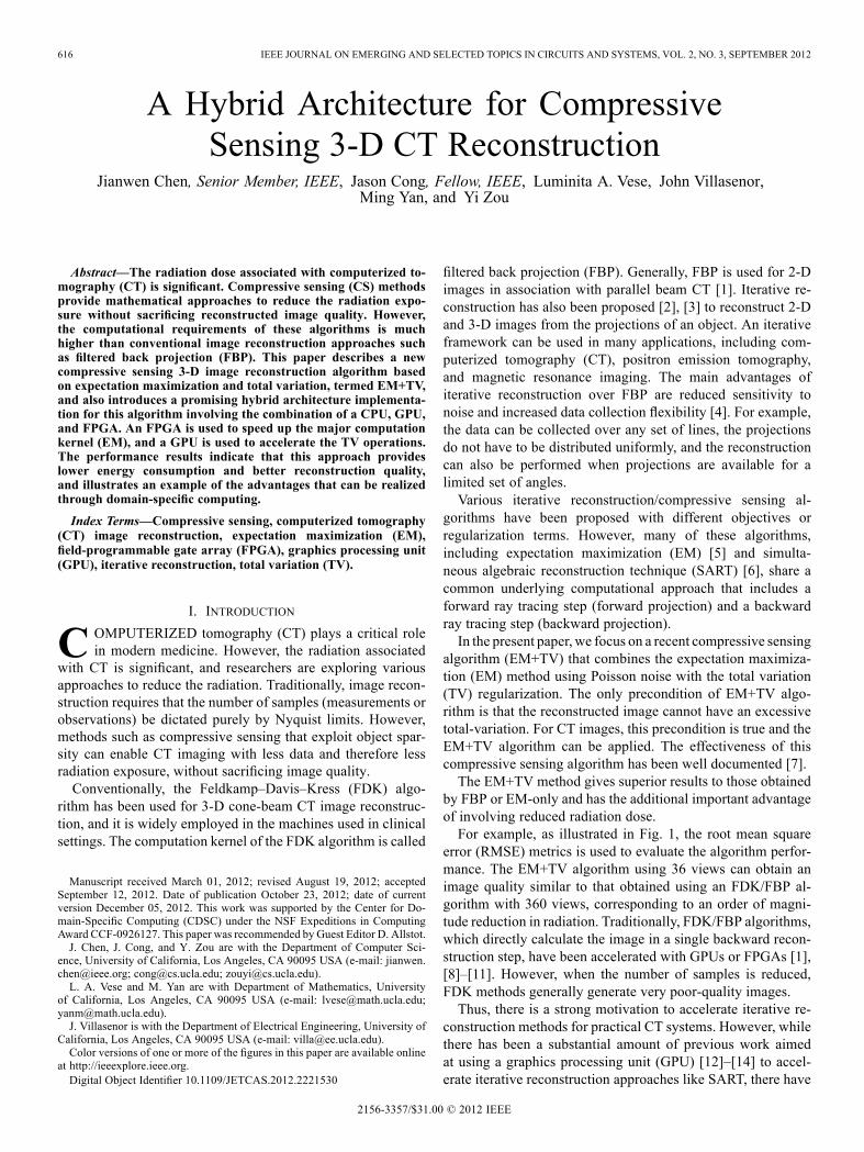
by FBP or EM-only and has the additional important advantageof involving reduced radiation dose.For example, as illustrated in Fig. 1, the root mean square
error (RMSE) metrics is used to evaluate the algorithm perfor-mance. The EM+TV algorithm using 36 views can obtain animage quality similar to that obtained using an FDK/FBP al-gorithm with 360 views, corresponding to an order of magni-tude reduction in radiation. Traditionally, FDK/FBP algorithms,which directly calculate the image in a single backward recon-struction step, have been accelerated with GPUs or FPGAs [1],[8]–[11]. However, when the number of samples is reduced,FDK methods generally generate very poor-quality images.Thus, there is a strong motivation to accelerate iterative re-
construction methods for practical CT systems. However, whilethere has been a substantial amount of previous work aimedat using a graphics processing unit (GPU) [12]–[14] to accel-erate iterative reconstruction approaches like SART, there have
CHEN et al.: A HYBRID ARCHITECTURE FOR COMPRESSIVE SENSING 3-D CT RECONSTRUCTION 617
Fig. 1. Reconstruction results by FBP with 36, 180, 360 views and EM+TV with 36 views (RMSE numbers are shown in parenthesis). (a) FDK/FBP with 36views. (b) FDK/FBP with 180 views. (c) FDK/FBP with 360 views. (d) EM+TV with 36 views.
been far fewer publications addressing field-programmable gatearray (FPGA) implementations of iterative reconstruction. In[15], for example, backward projection was implemented onan FPGA, and the forward projection step was performed ona GPU. GPUs and FPGAs of course have very different fea-tures. GPUs can have hundreds of parallel computing cores, andFPGAs can support high performance logic customization forspecific computations. If, for implementing an algorithm suchas EM+TV that has significant computational diversity, the ar-chitecture advantages of both a GPU and an FPGA can both beexploited, a higher performance design can be expected. More-over, the use of FPGA can help to significantly reduce the powerconsumption of the overall system.This paper presents a hybrid architecture for the EM+TV
compressive sensing algorithm [7] for CT image reconstruction.In this design, for EM part, the computations involved in theEM forward/backward ray tracing steps are based on MADD(multiply and add), requiring significant off-chip random ac-cess. Moreover, the computation and the required data accessfor one ray is proportional to the intersection length between theray and the object. These factors suggest that for the EM com-putations, an FPGA is a more suitable platform than a GPU. Weimplemented the ray-tracing forward projection and backwardprojection on a Convey HC-1ex multi-FPGA platform. By con-trast, the stencil computation kernel for the TV regularizationportion of the algorithm has attributes that make it well suitedfor a GPU. We also use CPUs for task preparation and sched-uling. The main features of the implementation described hereinclude the following.• A hybrid architecture that combines multiple FPGAs, aGPU and a CPU.
• A shared hardware module that can support both forwardprojection and backward projection.
• Separation of the machine configuration and the tracingengine.
• Better performance in terms of latency or throughput thana pure GPU implementation on Tesla or Fermi.
• Amapping of high-level algorithmic specification in C intoFPGA using the Xilinx AutoESL high-level-synthesis tool.
This paper introduces a new compressive sensing EM+TValgorithm for CT application. The related design and systemimplementation for this compressive sensing application arealso provided. The limitations and considerations for compres-sive sensing applications are analyzed in detail. The related
system design methodologies can be extended to other com-pressive sensing applications. The methodologies are the designflows, including the algorithm analysis, fixed point conversion,memory behavior analysis, computation kernel evaluation,parallel conflicts solution, data prefetching design, etc.The remainder of this paper is organized as follows. Section II
introduces the mathematical EM+TV algorithm. Section III de-scribes the computation analysis and the computation kernels.Architectural design decisions and parallelism are discussed inSection IV. Details regarding Implementation and optimizationsare given in Section V. SectionVI contains experimental results,and conclusions are contained in Section VII. An extended ab-stract of this work was presented in [16].
II. EM+TV ALGORITHM
The EM+TV algorithm, like many iterative algorithms, isbased on solving a system of linear equations
where is the original image repre-sented as a vector, is the measure-ment, and is a matrix describing the mapping fromthe original image to the measurement. is the discrete Radontransform [17], with each row describing an integral along onestraight line, and all the elements of are nonnegative.The expectation maximization (EM) algorithm [18] is
an iterative reconstruction algorithm. The noise can berepresented in as Poisson noise. Then, if is givenand is known, the conditional probability of is
. Given an initialestimate , the EM iteration for , is
(1)
The summations over and are from 1 to and , respec-tively.The total-variation regularization method was originally pro-
posed by Rudin, Osher, and Fatemi [19] to remove noise in animage while preserving edges. This technique is widely used inimage processing and can be expressed in terms of minimizingan energy function of the form ,where is viewed as a 2-D or 3-D image with spatial domain ,is usually a blurring operator, is the observed noisy-blurry
618 IEEE JOURNAL ON EMERGING AND SELECTED TOPICS IN CIRCUITS AND SYSTEMS, VOL. 2, NO. 3, SEPTEMBER 2012
image, and is a data fidelity term. For example, forGaussian noise, .In this paper, we combine the EM algorithm with TV regu-
larization as in [7]. We first briefly described the method in [7].In the classic EM algorithm, no prior information about the so-lution is provided. However, if we are given a priori knowledgethat the solution has homogeneous regions and sharp edges,this information can be applied to reconstruct an image withboth minimal total-variation and maximal probability. Underthis framework, the problem becomes
(2)where is a parameter for balancing the two terms: TV andEM. This is a convex constraint problem, and the optimal solu-tion can be found by solving the Karush–Kuhn–Tucker (KKT)conditions [20]
Using the positivity of , and the complementary slack-ness condition gives for all .Multiplying by gives
The last term on the left-hand side is an EM step (1), which canbe denoted by , giving
To solve the above equation in , with identified as notedabove, we use a semi-implicit iterative scheme for several steps,alternated with a EM step. The algorithm is shown below (con-vergence was shown in [21]).
Algorithm 1: EM+TV algorithm.
Input: ;
for do / IterMax: number ofouter iterations /
;
for do / K: number ofEMupdates /
; / Including oneand one /
end
;
end
Fig. 2. EM+TV block diagram.
III. COMPUTATION ANALYSIS
A. Algorithm Overview
To efficiently accelerate this compressive sensing algo-rithm, careful analysis of the computation is required. Fig. 2shows a high-level flow chart for the EM+TV algorithm asimplemented. It contains two updating modules: EMupdateand TVupdate. Since there is logic data dependency betweenEMupdate and TVupdate, the parallelism is found principallyin the internal processing of each module. EMupdate is morecritical for overall efficiency because it occurs in the inner-mostloop.Inside the EMupdate kernel, as illustrated in (1), a forward
projection is performed to obtain , followed by an element-wise division to get . Backward projection isthen performed to obtain or , and then theupdated value is obtained using element-wise scaling.Because the matrix is very large and sparse, is never
constructed explicitly. A ray-tracing based technique is used tocompute the forward projection and backward projection. TheEM+TV algorithm is very computationally intensive becauseit needs to invoke forward and backward projection repeatedly(on the order of 100 3 times in Fig. 2). By contrast, the con-ventional FDK algorithm only has a single backward projec-tion. Scaling, which is also an important element of the overallcomputation, is included in the projection step in our imple-mentation. Since EMupdate occupies the majority (93%) of thecomputation time, it is mapped to FPGAs for acceleration. ForTVupdate, since there is no data dependency within one TVcomputation iteration, so it can be easily mapped to a GPUmul-ticore architecture, giving significant acceleration.
B. Ray Tracer Engine
In this section, we focus on EMupdate. The EM algorithmis often implemented with a ray-driven forward projection anda voxel-driven back projection. To facilitate hardware resource
CHEN et al.: A HYBRID ARCHITECTURE FOR COMPRESSIVE SENSING 3-D CT RECONSTRUCTION 619
Fig. 3. Ray tracer block diagram.
sharing, we use a ray driven approach in both forward and back-ward projections. As a result, the forward and backward projec-tion in EM+TV will have the same iterative hierarchical struc-ture. The code for the forward and backward projection is shownin Fig. 4. The first level of iteration comprises the number ofviews (sources of the ray). The other two layers consist of thearray of 2-D detectors/sensors. The ray tracer engine works onone source/detector pair and is the computation kernel for bothforward and backward projections.As illustrated in Fig. 3, the ray tracer is composed of two
parts: tracer_precal and tracer_loop. For forward projectionand backward projection, the tracer has a similar computationalstructure. The tracer_precal part operates in the same manner.The only difference is in tracer_loop. In forward projection,tracer_loop will read pixels along with the ray and output onesinogram value for each ray; while in backward projection, thetracer_loop will read and update pixels along each ray. Thecode first identifies the direction for the next voxel in the rayand then it performs a MADD operation to accumulate thesinogram or update the image. Note that provides thecoefficients for the matrix . The forward projection attemptsto compute a line integral, while the backward projectionattempts to distribute a line integral onto the points on the ray.The tracing stops if the voxel hits the boundary of the object.
C. Intersection Computation
The function is responsible for computingthe intersection point of the ray with the object and identifyingthe parameter required for the tracing. Given a source coordinate
and destination , the procedure finds outthe intersection point with the object, which is a cube, , . The procedure first needs to
identify the intersection ratio in each dimension
(3)
This computes the x-dimension intersection ratio that is closerto the source. Similarly
(4)
The procedure then finds out the min and the max of the ratios
(5)
(6)
The ray intersects with the object if and only if .Once it has been established that the ray intersects with the ob-
ject, we then compute the near-end integer intersection coordi-nate using . Other parameters ,used in the tracing loop can be derived based on the coordinate
. A number of divisions are used in the procedure.
IV. OVERVIEW OF THE DESIGN
The design proposed in this paper is based on the combinationof Xilinx FPGA and Nvidia GPU. As illustrated in Fig. 5, theEMupdate portion of the algorithm is accelerated on the FPGAand the TVupdate portion is accelerated using the GPU.
A. Convey HC-1(ex) Platform and GPU Accelerator
The reconstruction algorithms considered here are generallymemory bound. The multi-FPGA platform Convey HC-1(ex)from Convey Computer Corporation was selected as the hard-ware platform due to its high external memory bandwidth andexcellent support for random data access. It uses an interleavedmemory scheme in which different FPGAs access the off-chipmemory using a shared memory model. The system employs anon-board crossbar to realize the interconnection. Fig. 6 showsthe system diagram for a Convey HC-1, which has Virtex5LX330 FPGAs. In the HC-1(ex) version of the platform,Virtex6 LX760 FPGAs are used. The system supports twomodes of interleaving schemes. In prime number interleave,the system uses a prime number of memory banks to bettersupport power-of-two strides.The Convey system has a total of 16 dual in-line memory
modules (DIMMs). As shown in Fig. 6, each memory controlleris connected to two DIMMs. The HC-1(ex) platform has fouruser FPGAs. Each FPGA has eight physical memory ports con-nected to eight memory controllers which run at 300 MHZ. Thecore design runs at 150 MHZ. Thus, effectively each FPGAis connected to 16 memory access ports through time multi-plexing. The peak off-chip memory bandwidth is 80 GB/s ifeach channel supplies one 64-bit data every cycle.The Nvidia Tesla C1060 is connected with Convey HC1-ex
platform. The Tesla C1060 is built on a 55 nm process and uti-lizes 240 CUDA Cores (Shaders). The Graphics Clock operatesat 1.3 GHz. You will find 4 GB GDDR3 of memory on board,running on a 512-bit memory bus at 1.6 GHz. This will providea maximum 102 GB/s of memory bandwidth.
B. Ray-by-Ray Parallelism Versus Voxel-by-Voxel Parallelism
As noted earlier, in the forward projection step, it is neces-sary to read the voxel values along the ray, and update (accumu-late) the corresponding sinogram value based on voxel values.In backward projection, the voxel values on the ray are updatedbased on the sinogram value associated with the ray. The codeshown in Fig. 4 is consistent with a ray-by-ray tracing approach.However, there are two approaches to parallelize the ray-
tracing forward/backward projection. One is a ray-by-ray ap-proach in the manner of Fig. 4, while the other is a voxel-by-voxel approach. For the forward projection, a ray-by-ray ap-proach is preferred because the accumulation of signogram datafor each ray is independent, and the need for concurrent up-dates on the (shared) sinogram data can be avoided. For thebackward projection, the voxel-by-voxel approach avoids ac-cess conflict. However, since the forward and backward projec-
620 IEEE JOURNAL ON EMERGING AND SELECTED TOPICS IN CIRCUITS AND SYSTEMS, VOL. 2, NO. 3, SEPTEMBER 2012
Fig. 4. Ray tracing core engine.
Fig. 5. Proposed hybrid system for EM+TV 3-D.
tion sharemany similar features, we use the ray-by-ray approachto enable the sharing of the hardware.Using a ray-by-ray approach also enables the tracing engine
more independence from the machine configuration. There arevarious source/detector configurations in CT, such as fan-beam,cone-beam, parallel-beam, etc. If a voxel-based approach isused, the list of sinograms that contribute to a voxel is highlydependent on the machine configuration. By contrast, in aray-tracing approach that realizes ray-by-ray based parallelism,once the set of rays are known, the hardware for tracing canbe reused. Using this architecture, it is much easier to migratefrom one machine setup (e.g., cone-beam) to another (e.g.,fan-beam). The procedure to cope with access conflicts forbackward projection in a ray-by-ray mode will be described inSection IV-D.
C. No Cache Interleaved Access
Ray tracing involves a significant amount of random data ac-cess. Those accesses present certain degree of reuse, however,
Fig. 6. System diagram of the Convey HC-1(ex) hybrid computer.
the reuses are hard to capture in the absence of a cache-basedsystem. Note it is also possible to use a block RAM (BRAM)scratchpad to capture reuse within the application design [15].However, that requires deep knowledge of the specific geometryof rays and how they intersect, and thus changes for differentimages and configurations. Based on these considerations theimplementation in the present paper does not use caching.Most existing FPGA computing boards prefer burst access.
In Li et al. [9], how to obtain good memory bandwidth on aFPGA-based system that uses burst transfers is introduced. Inthe convey HC-1(ex) system, parallel data access is not donethough a burst approach, but rather through interleaving. Re-quests from different channels can be processed in parallel ifthey fall into different banks. The system has 16 DIMMs and1024 banks in total in the memory system. So the possibility ofthe bank conflict is low if the parallel accesses are quite random.Such an interleaved memory design is also seen in the on-chipscratchpad memory of Nvidia GPUs. Because of the bandwidthof the external memory is already quite high, we do not imple-ment cache but talk to memory channels directly.
D. Resolving Access Conflicts in Parallel Backward Tracing
The forward projection can be easily parallelized by per-forming simultaneous computations for different source anddetector pairs. For backward projection, however, there aredependencies among views. Moreover, even within one viewthere can be conflicts when two parallel units update one pixel.To resolve the data conflicts within one view, atomic functionsthat guarantee the mutual exclusion of an address in memorycan be used. This approach has already been used to acceleratethe backward projection in a GPU environment [14]. However,an FPGA platform does not provide atomic operations on thememory system.To address this, we ensure that the computations for different
views (sources) are done sequentially. For the same view, thedetectors that are far enough apart are associated with one group.This ensures that there will be no conflicts within the group andthat all tracers in the group can be processed in parallel. As il-lustrated in Fig. 7, tracer lines having the same pattern can bechosen. The selection of the distance between two adjoint detec-tors involves a tradeoff between parallelism granularity and al-gorithm performance. In our implementation, we choose the dis-tance to be 5. The relationship between different distance choiceand the final reconstructed image quality is shown in Fig. 8. The
CHEN et al.: A HYBRID ARCHITECTURE FOR COMPRESSIVE SENSING 3-D CT RECONSTRUCTION 621
Fig. 7. Ray-based parallel mapping.
Fig. 8. RMSE performance with different parallel intervals.
figure shows the RMSE for the results with different intervals.As shown in the figure, when the interval is 5 8, the algorithmwithout atomic operation can obtain the same RMSE result aswith atomic operation.
E. Memory Bandwidth Calculation
Generally, most CT reconstruction applications are memorybound. For the EM+TV 3-D algorithm, there is data depen-dency between the projections in the EMupdate step. Therefore,a global data synchronization is required after forward projec-tion and backward projection in each iteration. For each iterationon data sets consistent in size with medical data (with 4 bytes data type size), the sino data and image data syn-chronization will require about 350 MB
of data communication.When, as is typicallythe case, hundreds of iterations are needed, the overall band-width requirement will be enormous. This places significantconstraints on the solution architecture. For example, simplyusing a platform with many computational cores will not besufficient.To explore this experimentally, we implemented the EM+TV
3-D application on a server with 24 cores with multithread tech-niques support. As illustrated in Fig. 9, when the core numberincreases, the speedup ratio does not increase linearly. Further-more, since the bottleneck is memory bandwidth, a maximumspeedup will be reached when the memory bandwidth on one
Fig. 9. EMTV speedup on a multicore cluster.
server is consumed, and the performance can not be further im-proved through the addition of more CPU cores. We also ex-plored a cloud-based solution using Message Passing Interface(MPI) framework on hundreds of cores. In this environment, thedata communication, which is performed through a network andinvolves high synchronization overhead, once again becomes acritical factor limiting performance.
V. IMPLEMENTATION AND OPTIMIZATION
In this section, the implementation details of this compressivesensing application are provided. And the optimization methodsused to improve the performance are also introduced.
A. Fixed Point Conversion
In order to realize an efficient FPGA implementation and ob-tain the maximum speedup, fixed-point operations are required.The associated quantization errors must be carefully balancedagainst the requirements of the application.We use a range anal-ysis technique to obtain the range of all the values in our data-path. Because the algorithm is iterative, for each iteration, theerrors caused by truncation on precision can accumulate. To ad-dress this, we used a dynamic precision analysis method to de-termine the number of fractional bits needed.In the EM+TV algorithm, the computation kernel ray tracer
is the most precision sensitive aspect of the algorithm. To ex-plore this, we use an original phantom image as a reference,and examine the mean square error (MSE) between the originalphantom and the reconstructed image as a function of precision.As illustrated in Fig. 10, the precision has a significant impact onthe reconstructed image quality.When 18 bits (corresponding toa precision of about ) are used, a fixed point implementa-tion can achieve the same reconstruction quality as a floatingpoint implementation. To provide an extra margin of accuracy,we used 20 fractional bits. Given the many multiplications anddivisions in the operations, to preserve the precision of ,64-bit arithmetic is used for the intermediate core operations.
B. Streaming Architecture
Function and the , as illustrated inFig. 3, can be executed in a task-level pipeline. We synthesize
622 IEEE JOURNAL ON EMERGING AND SELECTED TOPICS IN CIRCUITS AND SYSTEMS, VOL. 2, NO. 3, SEPTEMBER 2012
Fig. 10. Fractional bit width and reconstruction quality.
Fig. 11. Overall streaming architecture in one FPGA AE.
the and the individually to obtaintheir corresponding latency reports. Because the loop bound ofthe is not known, a simulation of test data is usedto compute the average-case latency of the . Thethroughput of the memory interfaces is also considered. The la-tency of the is approximately 1/4 of the latencyof the for a data set of size . Weimplement two modules and eightmodule in a single FPGA. As noted previously, each FPGAhas 16 virtual memory channels. Each module ex-changes data with two of them (one for read and one for write).The multi-FPGA system has four user FPGAs (Application En-gine or AE), and the workload distributed in a SIMD manner.EM implementation in one FPGA is shown in Fig. 11. To re-
alize such a diagram in C, we invoke the functiontwice and invoke the function of the tracer loop eight times.These different invocations take different FIFO channels andmemory interfaces as parameters, and the compiler parallelizesfunction calls that are independent. The round robin distribu-tion logic is coded in the function. At the re-ceiver side of , the control is just a simple counter tomaintain the number of rays processed. Each pro-cesses a predetermined number of rays. In the case where a raydoes not intersect with the object, the sends anappropriate flag to denote that no processing is needed, and thecounter is updated to maintain a correct exit condition. The con-trols that identify the list of sources and detectors are also codedin the function, along with the lookup tables ROM for
Fig. 12. Streaming architecture inside one kernel.
Fig. 13. Masking for backward projection.
functions. This framework makes it easy to change these con-trols to migrate this code for use with data from a machine witha different scanning setup.
C. Prefetching
Off-chip memory access has a long latency. For example,on the Convey platform, the latency is 125 cycles at 150MHz. And, the latency can be even longer if congestion (bankconflicts) occur. Given the large amount of random access inEM+TV, prefetching is critical to overall system performance.To address this, we model each memory access port with arequest FIFO and a response FIFO. As shown in Fig. 12, itis necessary to invoke two parallel functions inside the hi-erarchy of . One function is the “helper thread”
, which is responsible for sendingmemory requests for reads, and the other function is the “com-pute thread” , which obtains data fromthe response FIFO and write out the computed result intoanother request FIFO. This way, the helper threads can keepsending as many requests as possible, until the FIFO is full.Thus, the helper thread in essence is performing the function ofprefetching the required data, and the response FIFO serves asthe prefetch buffer. Fig. 12 depicts the architecture inside the
function.
D. Reducing the Data Accesses via Sparsity
Based on knowledge that the output image is sparse and thatvoxel data is nonnegative, we develop a simple heuristic to re-duce the amount of data access. In the beginning of an iteration,a single forward projection is performed. If any accumulatedsinogram value falls below a threshold, we conclude that anyimage value on that ray is likely to be close to zero. Based onthis, a 1-bit mask of the image called is con-structed. When the backward projection is performed, it is onlynecessary to update the voxels that are not masked, thereby re-ducing the number of data access in the backward projection.Fig. 13 shows the modified pseudo code.
CHEN et al.: A HYBRID ARCHITECTURE FOR COMPRESSIVE SENSING 3-D CT RECONSTRUCTION 623
TABLE IPERFORMANCE AND ENERGY NUMBERS FOR EMUPDATE COMPUTING KERNELS
E. Simultaneous Reconstruction of Two Images
After fixed point conversion, the external data accesses areall 32-bits wide. However, the memory interface of the multi-FPGA platform supports 64-bit memory interface. Because thedata access in the tracing is random, it is not feasible to use the64-bit interface to directly enlarge the application bandwidth.However, if there are two images to be reconstructed from dataacquired using the same machine setup, then the reconstruc-tion can be performed simultaneously by packing two 32-bitdata words from different images into each 64-bit word, and the
does not need to be modified.
F. GPU Accelerated TVupdate
In this EM+TV algorithm, TVupdate has three layers of iter-ations. The first layer comprises the number of views (sourcesof the ray). The other two layers consist of the array of 2-Ddetectors/sensors. There is no data dependency between the it-erations, and a fully parallel implementation can be used witha GPU. The Nvidia GPU has three layers of procesing units,which are called thread, block and grid layers, respectively.Given the natural mapping of three layer parallelism, TVupdatecan be implemented very efficiently on the GPU platform.
VI. EXPERIMENTAL RESULTS
The operations destined for hardware implementation are de-scribed in C and synthesized into verilog RTL using AutoESLHLS tool ver. 2011.1. The software operations is implementedwith Compute Unified Device Architecture (CUDA) Toolkit 3.2for parallel computing on a CUDA-enabled NVIDIA GPU. Thetarget application is a Cone-Beam CT system. An image of size512 512 256 is tested. It has 500 views (sources) and 73664 detector vectors. We parallelize the CPU code using p-threadand implement the GPU kernel using CUDA.
A. Kernel Performance and Energy Consumption
Table I presents the performance and the energy consump-tion of the forward projection kernel and the backward projec-tion kernel. The values in the table are obtained by averaging1000 invocations. The performance on a dual-core CPU andmany-core GPU is also reported. The CPU used is Intel Xeon5138 with 2.13 GHz clock frequency and 35 W TDP. The GPUcolumn denotes Nvidia Tesla C1060 with 240 cores and 200 WTDP.From Table I, the throughput of the FPGA design is the
highest. The power of the FPGA application engine is mea-sured using the Xilinx xPower tool. When the latency offorward and backward projection is combined, the multi-FPGAengine is about 50% faster than the CUDA implementation onTesla C1060. Since it is possible as described above to perform
TABLE IIFPGA AREA CONSUMPTION OF EMUPDATE
two reconstructions simultaneously, the FPGA-engine can bethree times faster than a Tesla C1060. As shown in the table,the FPGA platform is advantageous from an energy standpointas well.It is also notable that the execution time for backward pro-
jection is noticeably slower on other platforms. This is becausethe amount of data access is up to two times larger on theseplatforms (due to the need to read the voxel value and thenwrite it back). Also, more invocations (and synchronization) areneeded to avoid the conflicts and ensure correctness, which re-duces the available parallelism. In the FPGA design, by con-trast, the same architecture is used for both forward and back-ward projection. Each processing element (PE) is connected totwo memory channels, one for read and one for write. Thus, theexecution times of forward projection and backward projectionare similar.The hardware area consumption for the complete EMupdate
FPGA design is listed in Table II. The core computing RTLconsumes fewer logic slices, because the Convey’s PersonalityDevelopment Kit (PDK) infrastructure also consumes about10%–15% area. Most of the BRAM utilization is due to thePDK infrastructure. It should be emphasized that since thecomputation kernels are independent of the size of the imagedata, the designed kernel can work for different machine setups.The area of the EMupdate will keep almost same for differentdata.
B. Application Performance and Energy Consumption
The EM+TV 3-D CT application has been tested on the pro-posed hybrid system. The EM portion is done by the FPGA-sub-system and the TV portion is done by the GPU. The flowchartof the application is shown in Fig. 2, where the outer EM+TViterates 100 times, and the inner EM step iterates three timesfor each EM+TV iteration. The hybrid configuration connectsthe Tesla C1060 onto the Convey HC-1(ex) platform. After oneEM iteration completes, the image data is copied into the GPUmemory space and the TV CUDA kernel starts; the data transferdoes not add substantial overhead in this case. We experimen-tally confirmed that the pipelined data transfer (FPGA copro-cessor-sidememory to PCI-e) can achieve close to 1 GB/s, whileeach EM iteration only needs to copy 256 MB image data toGPU. And similarly we need to do the transfer backwards whenone TV invocation finishes. The data communication only adds
624 IEEE JOURNAL ON EMERGING AND SELECTED TOPICS IN CIRCUITS AND SYSTEMS, VOL. 2, NO. 3, SEPTEMBER 2012
TABLE IIIAPPLICATION PERFORMANCE AND ENERGY CONSUMPTION
a modest amount of extra time for each EM+TV iteration. Be-cause the TV kernel is a highly regular stencil computation,about a 10 speed up can be achieved with GPU. The execu-tion time of the TV is much shorter than EM (no more than 5%of the overall time consumption). The performance of the pro-posed hybrid architecture is compared with that of the CPU onlyor GPU only architectures, as illustrated in Table III. The pro-posed architecture has the highest performance and minimumenergy consumption.Compared with the GPU/CPU only [14] or FPGA only [15]
implementations, the proposed hybrid architecture takes advan-tages of the FPGA and GPU at the same time. Since the areaconsuming parts, such as TVupdate, has been efficiently accel-erated with GPU, the area consumption is lower than that of theFPGA only implementations. For the power consumption, withthe usage of FPGA, the power consumption of the proposed ar-chitecture is less than 1/3 of the CPU implementation and 1/5of the GPU implementation.
VII. CONCLUSION
We have proposed a new architecture for implementingcompressive sensing reconstruction. This system is based ona hybrid involving both FPGA and GPU computations, andhas significant performance advantages over a GPU-only orcloud-based multi-server approach. The advantages involvenot only speed, but also energy consumption. While we haveexplored this in the context of EM+TV, we believe that thereis a broader opportunity to apply hybrid computing approachesto a wide variety of compressive sensing processing. Solutionssuch as the approach presented here reduce the computationtime associated with compressive sensing, and thus make itmore practical to perform medical imaging at lower radiationexposure levels.
REFERENCES
[1] S. Coric, M. Leeser, E. Miller, and M. Trepanier, “Parallel-beambackprojection: An FPGA implementation optimized for medicalimaging,” in Proc. Int. Symp. Field-Programmable Gate Arrays, 2002,pp. 217–226.
[2] L. Shepp and B. Logan, “The Fourier reconstruction of a head section,”IEEE Trans. Nucl. Sci., vol. 21, pp. 21–34, 1974.
[3] X. Pan, E. Sidky, and M. Vannier, “Why do commercial CT scannersstill employ traditional filtered back-projection for image reconstruc-tion?,” Inverse Problems, vol. 25, p. 123009, 2009.
[4] A. Kak and M. Slaney, Principles of Computerized TomographicImaging. Philadelphia, PA: SIAM, 2001.
[5] A. P. Dempster, N. M. Laird, and D. B. Rubin, “Maximum likelihoodfrom incomplete data via the EM algorithm,” J. R. Stat. Soc., vol. 39,no. 1, pp. 1–38, 1977.
[6] A. H. Andersen and A. C. Kak, “Simultaneous algebraic reconstructiontechnique (SART): A superior implementation of the ART algorithm,”Ultrason. Imag., vol. 6, pp. 81–94, Jan. 1984.
[7] M. Yan and L. A. Vese, “Expectation maximization and total varia-tion-based model for computed tomography reconstruction from un-dersampled data,” in Proc. SPIE Conf. Med. Imag.: Phys. Med. Imag.,2011, vol. 7961, p. 79612x.
[8] N. Gac, S. Mancini, M. Desvignes, and D. Houzet, “High speed 3-Dtomography on CPU, GPU, and FPGA,” EURASIP J. Embedded Syst.vol. 2008, pp. 5:1–5:12, Jan. 2008.
[9] J. Li, C. Papachristou, and R. Shekhar, “An FPGA-based computingplatform for real-time 3-D medical imaging and its application to cone-beam CT reconstruction,” J. Imag. Sci. Technol., vol. 49, pp. 237–245,2005.
[10] H. Scherl, B. Keck, M. Kowarschik, and J. Hornegger, “Fast GPU-based CT reconstruction using the common unified device architec-ture (CUDA),” in IEEE Nucl. Sci. Symp. Conf. Rec., 2007, vol. 6, pp.4464–4466.
[11] J. Xu, N. Subramanian, A. Alessio, and S. Hauck, “Impulse C vs.VHDL for accelerating tomographic reconstruction,” in Proc. 18thIEEE Annu. Int. Symp. Field-Programmable Custom Comput. Mach.(FCCM), May 2010, pp. 171–174.
[12] B. Keck, H. Hofmann, H. Scherl, M. Kowarschik, and J. Hornegger,“GPU-accelerated SART reconstruction using the CUDA program-ming environment,” in Proc. SPIE, E. Samei and J. Hsieh, Eds., LakeBuena Vista, 2009, vol. 7258.
[13] F. Xu and K. Mueller, “Accelerating popular tomographic reconstruc-tion algorithms on commodity PC graphics hardware,” IEEE Trans.Nucl. Sci., vol. 52, no. 3, pp. 654–663, Jun. 2005.
[14] J. Chen, M. Yan, L. A. Vese, J. Villasenor, A. Bui, and J. Cong,“EM+TV for reconstruction of cone-beam CT with curved detectorsusing GPU,” in Proc. Int. Meeting Fully Three-Dimensional ImageReconstruct. Radiol. Nucl. Med., 2011, pp. 363–366.
[15] D. Stsepankou, K. Kommesser, J. Hesser, and R. Manner, “Real-time3-D cone beam reconstruction,” in Nucl. Sci. Symp. Conf. Rec., Oct.2004, vol. 6, pp. 3648–3652.
[16] J. Chen, J. Cong, M. Yan, and Y. Zou, “FPGA-accelerated 3-Dreconstruction using compressive sensing,” in 20th ACM/SIGDA Int.Symp. Field-Programmable Gate Arrays (FPGA 2012), Feb. 2012,pp. 163–166.
[17] G. Beylkin, “Discrete radon transform,” IEEE Trans. Acoust., SpeechSignal Process., vol. 35, no. 2, pp. 162–172, Feb. 1987.
[18] L. Shepp and Y. Vardi, “Maximum likelihood reconstruction for emis-sion tomography,” IEEE Trans. Med. Imag., vol. 1, no. 2, pp. 113–122,Oct. 1982.
[19] L. Rudin, S. Osher, and E. Fatemi, “Nonlinear total variation basednoise removal algorithms,” Phys. D., vol. 60, pp. 259–268, 1992.
[20] S. Boyd and L. Vandenberghe, Convex Optimization. Cambridge,U.K.: Cambridge Univ. Press, 2004.
[21] M. Yan, J. Chen, L. A. Vese, J. D. Villasenor, A. A. T. Bui, and J.Cong, “EM+TV based reconstruction for cone-beam CT with reducedradiation,” in ISVC, G. Bebis, R. D. Boyle, B. Parvin, D. Koracin, S.Wang, K. Kim, B. Benes, K. Moreland, C. W. Borst, S. DiVerdi, Y.-J.Chiang, and J. Ming, Eds., 2011, vol. 6938, pp. 1–10.
Jianwen Chen (SM’12) received the Ph.D. degreein electrical engineering from Tsinghua University,Beijing, China, in 2007.From 2007 to 2010, he was a staff researcher in
IBM research, where he conducted research on wire-less communications systems and multi-core videocoding architectures. In September 2010, he joinedthe Image Communications Lab and the Center ofDomain-Specific Computing (CDSC), Universityof California, Los Angeles (UCLA), where he iscurrently focusing on the research of high efficiency
video coding (HEVC) techniques, high performance computing architectureand applications. His research interests include high performance computingarchitecture, video signal processing and compression, video communicationover challenging networks, cloud computing, and wireless communicationssystem. He has over 40 publications in these areas.Dr. Chen served as the Chairman of the MPEG Internet Video Codec Ad-hoc
Group from February 2012. He was nominated as the Chancellor’s PostdoctoralResearcher of UCLA in 2012.
CHEN et al.: A HYBRID ARCHITECTURE FOR COMPRESSIVE SENSING 3-D CT RECONSTRUCTION 625
Jason Cong (F’00) received the B.S. degree incomputer science from Peking University, Beijing,China, in 1985, and the M.S. and Ph.D. degrees incomputer science from the University of Illinois,Urbana-Champaign, in 1987 and 1990, respectively.Currently, he is a Chancellor’s Professor at the
Computer Science Department of University ofCalifornia, Los Angeles (UCLA), the Director ofCenter for Domain-Specific Computing (CDSC),co-Director of UCLA/Peking University JointResearch Institute in Science and Engineering, and
co-Director of the VLSI CAD Laboratory. He also served as the DepartmentChair from 2005 to 2008. His research interests include synthesis of VLSIcircuits and systems, programmable systems, novel computer architectures,nano-systems, and highly scalable algorithms.
Luminita A. Vese received theM.S. degree inmathe-matics fromWest University of Timisoara, Romania,in 1993, and the M.S. and Ph.D. degrees in appliedmathematics from University of Nice, Sophia, An-tipolis, France, in 1992 and 1997, respectively.She is currently a Professor of Mathematics at the
University of California, Los Angeles (UCLA). Be-fore joining the UCLA faculty, she held postdoctoralresearch and teaching positions at the Universityof Nice, the University of Paris IX Dauphine, andUCLA. Her research interests include variational
John Villasenor is a Professor of electrical engi-neering at the University of California, Los Angelesand a nonresident Senior Fellow in GovernanceStudies and the Center for Technology Innovationat the Brookings Institution. His current researchfocuses on the technology and policy challengesassociated with how information is acquired, pro-cessed, and delivered in an efficient and securemanner.
Ming Yan received the B.S. and M.S. degrees incomputational mathematics from University ofScience and Technology of China, Hefei, China,in 2005 and 2008, respectively. He received thePh.D. degree from the Department of Mathematics,University of California, Los Angeles in 2012.He is a postdoctoral fellow in the Department of
Computational and Applied Mathematics, Rice Uni-versity, Houston, TX. His current research interestsinclude variational and optimization methods forimage and signal processing.
Yi Zou received the B.E. and M.E. degrees incomputer science from Tsinghua University, Beijing,China, in 2004 and 2006, respectively, and the Ph.D.degree in computer science from University ofCalifornia, Los Angeles, in 2012.His research interests include medical image
processing and high performance computing usingFPGAs and GPUs.


![[Engelberg] Compressive Sensing](https://static.documents.pub/doc/80x56/55cf9985550346d0339dc8ee/engelberg-compressive-sensing.jpg)


