Table of Contents TABLE OF CONTENTS ............................................................................................................................................3 CONTACT INFORMATION .....................................................................................................................................5 PRODUCT INFORMATION.....................................................................................................................................5 WARNINGS.................................................................................................................................................................6 CAUTIONS..................................................................................................................................................................6 ATTACHMENTS........................................................................................................................................................7
Power Data Sheets 438 0016PD AttSchematic 439 0050P AttSchematic w/ capacitor 439 0050P-1 Att
GE Critical Power 6420129P Manual
Page 4 Issue 22, May 2015
- This page intentionally left blank -
GE Critical Power 6420129P Manual
Issue 22, May 2015 Page 5
Product Information Please take a moment when the product is new to fill in this information.
First, locate the product information label. This is typically located on the upper front of the equipment frame, or on the rear of the frame. Fill in the part number, as it appears on the label, in the space below.
Warnings Cautions1. Electrical shock hazard. Do not attempt to
remove, maintain, or install this equipment withpower applied. Personnel that attempt to workon this equipment with the power applied maysubject themselves or others to electrical shockthat may cause serious injury or death.
2. The use of this equipment by unauthorized oruntrained personnel should not be attempted.Personnel that work on this equipment withoutthe proper training may subject themselves orothers to electrical shock that may cause seriousinjury or death.
3. Do not attempt to work on this equipment if it is,or has been, exposed to a high moisturecondition. It is recommended the equipment bereturned to GE to be properly tested.Working on this equipment during a highmoisture condition subjects the user to electricalshock that may cause serious injury or death.
4. Use of an attachment other than one approvedby GE will void any and all warranties,implied or other, and will increase risk of fire, ormay possibly cause electrical shock, injury, ordeath to personnel.
5. Do not operate this equipment if it has beendropped or otherwise damaged. Trying tooperate this equipment if it has been damagedsubjects yourself or others to electrical shockthat may cause serious injury or death.
6. Before you proceed, ensure the input source isnot live and the input circuit breaker(s)/fuse(s)has been tripped or removed. If theseprocedures have not been followed and theinput/output power is live, serious personnelinjury or death may occur.
7. A rack/shelf may contain several operatingsystems. If there is another system in thegeneral area you want to install this system, becautious of any exposed connectors or wiresand, with permission, remove power to the othersystems. Failure to take the necessary safetyprecautions subjects the installer ormaintenance personnel to severe electricalshock that may cause serious injury or death.
8. This equipment may connect to lead-acidbatteries. Battery posts, terminals, and relatedaccessories contain lead and lead compounds,chemicals known to the state of California tocause cancer and birth defects or otherreproductive harm. Wash hands aftertouching batteries.
1. Follow proper grounding instructions.
2. If connecting batteries, remove the battery-box-fuse or trip the circuit breaker. Checkbatteries and connections for proper polarityand power before connecting the batteries tothe system
3. To remove the circuit breakers or fuses, theDC and/or AC input to the system will need tobe disconnected, thereby disabling the systemoutput to the load(s). Take the necessaryprecautions and inform the plant engineer thatthe system output power to the loads will bedisabled.
4. Before performing any maintenance, ensureAC or DC power is not applied to the system.
5. Fuse holders, fuses, and circuit breakers arenot to be loaded to more than 80 percent oftheir ampere rating.
GE Critical Power A & B Distribution Fuse Panel Manual
Page 2 Issue 22, May 2015
-This page intentionally left blank-
GE Critical Power A & B Distribution Fuse Panel Manual
Issue 22, May 2015 Page 3
Table of Contents TABLE OF CONTENTS ...............................................................................................................................3 SECTION 1: SPECIFICATIONS...................................................................................................................5
1.1 GENERAL. ..................................................................................................................................5 1.2 OUTPUT RATINGS ....................................................................................................................5 1.3 INPUT RATINGS ........................................................................................................................5 1.4 STANDARD FEATURES ............................................................................................................6 1.5 ENVIRONMENTAL RATINGS....................................................................................................6
4.1 INSTALLER INFORMATION NOTES.......................................................................................11
GE Critical Power A & B Distribution Fuse Panel Manual
Page 4 Issue 22, May 2015
- This page intentionally left blank -
GE Critical Power A & B Distribution Fuse Panel Manual
Issue 22, May 2015 Page 5
SECTION 1: SPECIFICATIONS 1.1 GENERAL.
The 6170021P & W "A" & "B" Distribution Fuse Panel is designed to provide -48 VDC for two (2) separate fused distribution load points. The two (2) fused load distributions are designated as "A" Distribution and "B" Distribution.
The 6170094P & W "A" & "B" Distribution Fuse Panel is the same as 6170021P & W except it has an added feature of two (2) filter capacitors.
"B" Distribution also provides ten (10) GMT type fuse distribution points.
The "A" & "B" Distribution Fuse Panel can be mounted in a 23 inch relay type rack. The fuse panel is six (6) inches in height, mounts in three (3) frame positions and consists of the following equipment:
A. "A" Distribution fusing consists of the following:
1. Front access fuseholder - holds one (1) TPS cartridge type fuse. The fuse size can rangefrom 3 to 70 Amps.
B. "B" Distribution fusing consists of the following:
1. Front access fuseholder - holds one (1) TPS cartridge type fuse. The fuse size can rangefrom 3 to 70 Amps.
2. Front access fuseholder - holds ten (10) GMT type fuses. The fuse size can range from 1/4to 10 Amps.
C. Metering (Load Current)
D. Ground Bar (Isolated) - This ground bar is common for both "A" & "B" Distribution fusing.
E. Alarm Monitoring - Complete alarming of fuses with indicators and two (2) sets of "Form C" contacts per distribution.
1.2 OUTPUT RATINGS
1.2.1 VOLTAGE: The system provides an output voltage of -48 VDC.
1.2.2 CURRENT: The system can distribute up to a MAXIMUM of 100 Amps of -48 VDC power per distribution.
1.3 INPUT RATINGS
1.3.1 VOLTAGE: -48 VDC.
1.3.2 CURRENT: 100 Amps per side.
GE Critical Power A & B Distribution Fuse Panel Manual
Page 6 Issue 22, May 2015
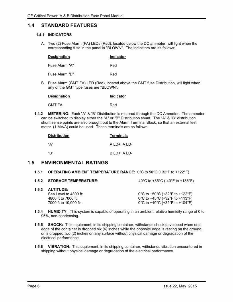
1.4 STANDARD FEATURES
1.4.1 INDICATORS
A. Two (2) Fuse Alarm (FA) LEDs (Red), located below the DC ammeter, will light when the corresponding fuse in the panel is "BLOWN". The indicators are as follows:
Designation Indicator
Fuse Alarm "A" Red
Fuse Alarm "B" Red
B. Fuse Alarm (GMT FA) LED (Red), located above the GMT fuse Distribution, will light when any of the GMT type fuses are "BLOWN".
Designation Indicator
GMT FA Red
1.4.2 METERING: Each "A" & "B" Distribution is metered through the DC Ammeter. The ammeter can be switched to display either the "A" or "B" Distribution shunt. The "A" & "B" distribution shunt sense points are also brought out to the Alarm Terminal Block, so that an external test meter (1 MV/A) could be used. These terminals are as follows:
Distribution Terminals
"A" A LD+, A LD-
"B" B LD+, A LD-
1.5 ENVIRONMENTAL RATINGS
1.5.1 OPERATING AMBIENT TEMPERATURE RANGE: 0°C to 50°C (+32°F to +122°F)
1.5.2 STORAGE TEMPERATURE: -40°C to +85°C (-40°F to +185°F)
1.5.3 ALTITUDE: Sea Level to 4800 ft: 0°C to +50°C (+32°F to +122°F) 4800 ft to 7000 ft: 0°C to +45°C (+32°F to +113°F) 7000 ft to 10,000 ft: 0°C to +40°C (+32°F to +104°F)
1.5.4 HUMIDITY: This system is capable of operating in an ambient relative humidity range of 0 to 95%, non-condensing.
1.5.5 SHOCK: This equipment, in its shipping container, withstands shock developed when one edge of the container is dropped six (6) inches while the opposite edge is resting on the ground, or is dropped two (2) inches on any surface without physical damage or degradation of the electrical performance.
1.5.6 VIBRATION: This equipment, in its shipping container, withstands vibration encountered in shipping without physical damage or degradation of the electrical performance.
GE Critical Power A & B Distribution Fuse Panel Manual
Issue 22, May 2015 Page 7
SECTION 2: DIMENSIONS
.ncI,ECOP II
.ncECOP III ,TM
TM
TOP VIEW
FRONT VIEW (with cover removed)
FRONT VIEW
+ GND Returns Load Terminals
Battery Terminations
GE Critical Power A & B Distribution Fuse Panel Manual
Page 8 Issue 22, May 2015
- This page intentionally left blank -
GE Critical Power A & B Distribution Fuse Panel Manual
Issue 22, May 2015 Page 9
SECTION 3: INSTALLER CONNECTIONS
Torque 2 hole lug connections to 7.6 ft/lbs
GE Critical Power A & B Distribution Fuse Panel Manual
Page 10 Issue 22, May 2015
Torque 2 hole lug connections to 7.6 ft/lbs
GE Critical Power A & B Distribution Fuse Panel Manual
This panel contains electrolytic capacitors that require pre-charge BEFORE the panel can become operational.
COMPONENTS REQUIRED:
A. Pigtail lampholder (Eagle Electric Mfg Co. #145 or equivalent).
B. Lamp (100 Watt 120V)
1. Remove all fuses / close all circuit breakers for both positions, A and B. Remove all GMTfuses from the unit.
2. At the source panel, connect the pigtail lamp holder in series with the source fuse/circuitbreaker terminals until the lamp extinguishes (caps charged).
3. With the lamp still connected in series with the source fuse/circuit breaker terminals, insertthe fuse or close circuit breaker.
4. Perform steps 1 and 2 for both, positions A and B. Once both positions are complete theGMT fuses may be installed.
5. Remove pigtail lampholder.
4.1 INSTALLER INFORMATION NOTES
It is imperative that the installer bends and secures all input and output power cables before connecting them to the busses. There should be no strain on the cable or connection point. For detailed information on securing, bending, and connecting power cables, refer to SBC TP76300 Installation Instructions, or equivalent.
4.1.1 INPUT (-48VDC)
4.1.2 OUTPUT (-48VDC MAIN)
4.1.3 OUTPUT (-48VDC GMT)
Terminal Capacity Terminal Type
8 to 2 Ga 2 hole crimp lug 0.25 stud on 0.625 centers
Terminal Capacity Terminal Type
8 to 2 Ga 1 hole crimp lug, 0.25 stud
Terminal Capacity Terminal Type
16 to 10 Ga 1 hole crimp lug, #8 stud
GE Critical Power A & B Distribution Fuse Panel Manual
Page 12 Issue 22, May 2015
4.1.3 ALARMS (Dry Contacts)
4.1.4 TORQUE. The following torque requirements are for connections to the ground and battery termination bars:
4.1.5 Wire sizes are based on voltage drop considerations and National Electric Code Table 310-16 for copper wire.