For Technical Support contact Sensoray Co., Inc. 7313 SW Tech Center Dr., Tigard, Oregon 97223, USA Tel:(503) 684-8005 Fax:(503) 684-8164 e-mail: [email protected]www.sensoray.com Sensoray Model 626 PCI Multifunction I/O Board Revision F January 28, 2004 INSTRUCTION MANUAL
Transcript
For Technical Support contact Sensoray Co., Inc. 7313 SW Tech Center Dr., Tigard, Oregon 97223, USA
TABLE OF CONTENTS 1. LIMITED WARRANTY.................................................................................................................................................. 4
2. SPECIAL HANDLING INSTRUCTIONS..................................................................................................................... 4
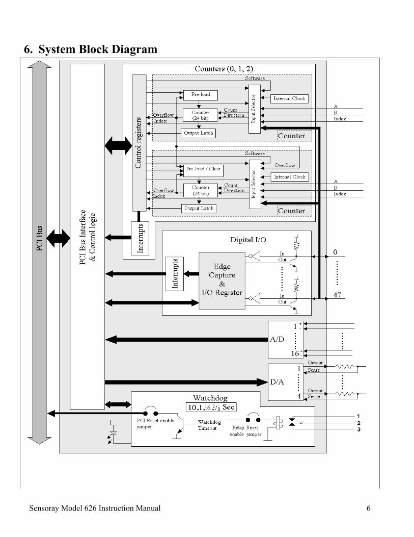
6. SYSTEM BLOCK DIAGRAM........................................................................................................................................ 6
8. INITIAL STATES AFTER RESET................................................................................................................................ 8
9. DIGITAL I/O .................................................................................................................................................................... 9
9.1 OVERVIEW ...................................................................................................................................................................... 9 9.2 WRITING TO THE DIGITAL OUTPUTS ............................................................................................................................. 10
9.2.1 Digital Outputs 0-6 used as Counter Overflows.................................................................................................. 10 9.3 READING THE DIGITAL INPUTS...................................................................................................................................... 10 9.4 CAPTURE DIGITAL INPUT EDGES................................................................................................................................... 11
9.5 READING EDGE CAPTURE STATUS REGISTERS.............................................................................................................. 12 9.5.1 Reading which channels have Captured Edges ................................................................................................... 12 9.5.2 Reading the Status of the Interrupt Enable Registers .......................................................................................... 12 9.5.3 Reading the Status of the Edge Selection Register .............................................................................................. 12 9.5.4 Reading the Status of the Capture Enable Register............................................................................................. 13 9.5.5 Clearing a Captured Edge................................................................................................................................... 13
9.6 DIGITAL INPUT INTERRUPTS.......................................................................................................................................... 13 9.6.1 Selecting Interrupt on Edge Capture ................................................................................................................... 13 9.6.2 Digital Input Interrupt Handling ......................................................................................................................... 13
10.5.1 Software Control of the Index ......................................................................................................................... 20 10.5.2 Multiplier......................................................................................................................................................... 20 10.5.3 Software Control Of Direction & Count Generation ...................................................................................... 20
10.6 DRIVING COUNTER B FROM COUNTER A’S OVERFLOW ........................................................................................... 20
Sensoray Model 626 Instruction Manual Page 2
10.7 TRIGGERING A COUNTER LOAD............................................................................................................................... 21 10.8 CLEARING COUNTER B FROM COUNTER A’S OVERFLOW ........................................................................................ 21 10.9 LATCHING THE COUNTERS....................................................................................................................................... 21 10.10 INTERRUPTS ............................................................................................................................................................. 22
10.10.1 Interrupts While Under Battery Backup ......................................................................................................... 22 10.10.2 Interrupt source Selection............................................................................................................................... 22 10.10.3 Clearing An interrupt...................................................................................................................................... 22 10.10.4 Counter Interrupt Handling............................................................................................................................ 22
13. ANALOG INPUTS .................................................................................................................................................... 26
14. ANALOG OUTPUTS ................................................................................................................................................ 26
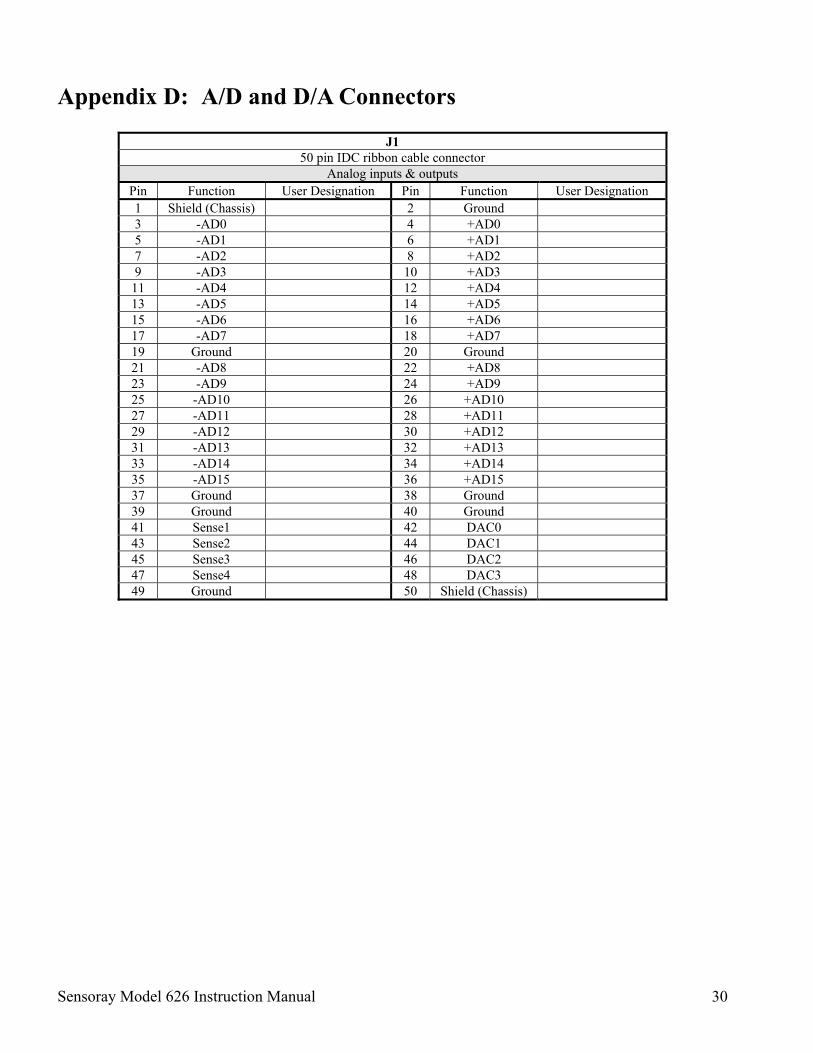
APPENDIX D: A/D AND D/A CONNECTORS................................................................................................................... 30
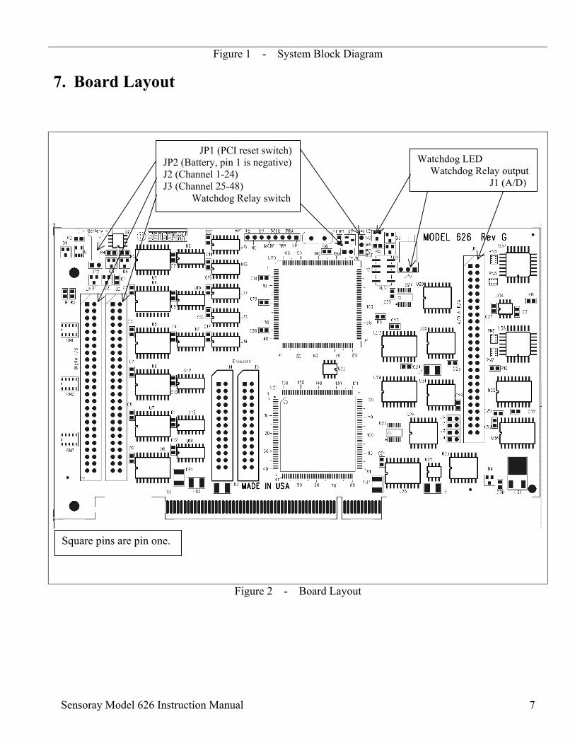
FIGURES Figure 1 System Block Diagram .................................................................................................................6 Figure 2 Board Layout.................................................................................................................................7 Figure 3 Digital I/O Channels .....................................................................................................................9 Figure 4 Differential pair encoder. ............................................................................................................16 Figure 5 Single ended encoder. (TTL or CMOS)......................................................................................16 Figure 6 Single ended event counter with external count direction & index control...............................16 Figure 7 Block diagram of a counter pair..................................................................................................17 TABLES Table 1 MISC1 & MISC2 Registers Initial States..................................................................................8 Table 2 Digital I/O Initial States ..............................................................................................................8 Table 3 Counter Initial States ..................................................................................................................8 Table 4 Digital I/O Register Offsets.........................................................................................................9 Table 5 Writing to Digital Outputs ........................................................................................................10 Table 6 Reading Digital Inputs ..............................................................................................................10 Table 7 Selecting Positive or Negative Edge Capture ..........................................................................11 Table 8 Enabling & Disabling Edge Capture .......................................................................................11 Table 9 Reading Captured Edges ..........................................................................................................12 Table 10 Reading the Status of the Interrupt Enable Registers .........................................................12
Sensoray Model 626 Instruction Manual Page 3
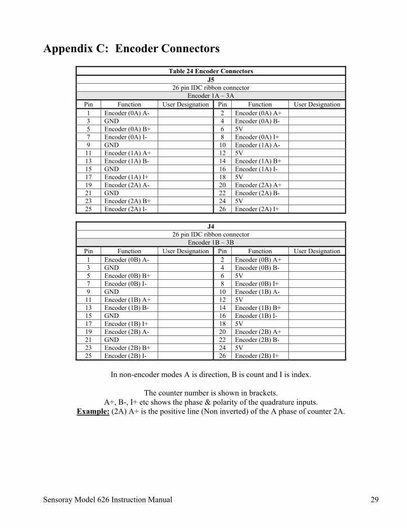
Table 11 Reading the Status of the Edge Selection Registers .............................................................12 Table 12 Reading the Status of the Capture Enable Registers ...........................................................13 Table 13 Selecting Interrupt on Edge Capture ....................................................................................13 Table 14 Counter Registers ....................................................................................................................16 Table 15 CR1A 00 (hex) Read/Write.....................................................................................................18 Table 16 CR1B 02 (hex) Read/Write .....................................................................................................18 Table 17 CR1B 02 (hex) Read ................................................................................................................18 Table 18 Digital inputs as Counter input controls ...............................................................................19 Table 19 Write to MISC1 88 (hex).........................................................................................................23 Table 20 Read from MISC1 88 (hex).....................................................................................................23 Table 21 Write to MISC2 90 (hex).........................................................................................................23 Table 22 Read from MISC2 92 (hex).....................................................................................................23 Table 23 Reading back Digital Outputs 1-7 Source Selection.............................................................25 Table 24 Encoder Connectors ................................................................................................................29
Sensoray Model 626 Instruction Manual Page 4
1. Limited Warranty
Sensoray Company, Incorporated (Sensoray) warrants the Model 626 hardware to be free from defects in material and workmanship and perform to applicable published Sensoray specifications for two years from the date of shipment to purchaser. Sensoray will, at its option, repair or replace equipment that proves to be defective during the warranty period. This warranty includes parts and labor.
The warranty provided herein does not cover equipment subjected to abuse, misuse, accident, alteration, neglect, or unauthorized repair or installation. Sensoray shall have the right of final determination as to the existence and cause of defect.
As for items repaired or replaced under warranty, the warranty shall continue in effect for the remainder of the original warranty period, or for ninety days following date of shipment by Sensoray of the repaired or replaced part, whichever period is longer.
A Return Material Authorization (RMA) number must be obtained from the factory and clearly marked on the outside of the package before any equipment will be accepted for warranty work. Sensoray will pay the shipping costs of returning to the owner parts that are covered by warranty.
Sensoray believes that the information in this manual is accurate. The document has been carefully reviewed for technical accuracy. In the event that technical or typographical errors exist, Sensoray reserves the right to make changes to subsequent editions of this document without prior notice to holders of this edition. The reader should consult Sensoray if errors are suspected. In no event shall Sensoray be liable for any damages arising out of or related to this document or the information contained in it.
EXCEPT AS SPECIFIED HEREIN, SENSORAY MAKES NO WARRANTIES, EXPRESS OR IMPLIED, AND SPECIFICALLY DISCLAIMS ANY WARRANTY OF MERCHANTABILITY OR FITNESS FOR A PARTICULAR PURPOSE. CUSTOMER’S RIGHT TO RECOVER DAMAGES CAUSED BY FAULT OR NEGLIGENCE ON THE PART OF SENSORAY SHALL BE LIMITED TO THE AMOUNT THERETOFORE PAID BY THE CUSTOMER. SENSORAY WILL NOT BE LIABLE FOR DAMAGES RESULTING FROM LOSS OF DATA, PROFITS, USE OF PRODUCTS, OR INCIDENTAL OR CONSEQUENTIAL DAMAGES, EVEN IF ADVISED OF THE POSSIBILITY THEREOF.
2. Special Handling Instructions
The Model 626 circuit board contains CMOS circuitry that is sensitive to Electrostatic Discharge (ESD).
Special care should be taken in handling, transporting, and installing the 626 to prevent ESD damage to the board. In particular:
• Do not remove the circuit board from its protective anti-static bag until you are ready to configure the board for installation.
• Handle the circuit board only at grounded, ESD protected stations.
• Remove power from the PCI system before installing or removing the circuit board.
Sensoray Model 626 Instruction Manual 5
3. Introduction The Sensoray model 626 is a Multifunction I/O card. Some of the features include: • 48 digital I/O channels. • 20 of the digital I/O channels have edge detection and interrupt capability. • 7 of the digital Outputs can be used as counter overflow outputs. • Digital I/O connectors are industry standard pinouts. • Watchdog timer with several selectable reset periods that can reset the PCI bus. • Six 24 bit up/down counters arranged in 3 pairs with:
• Inputs that can be driven in various modes (1x, 2x, 4x) from incremental encoders inputs, the digital inputs, the paired counter’s overflow, the system clock or software driven.
• Can generate an interrupt on counter overflow or encoder/digital input index. • Can be preloaded/cleared on an overflow. • Output of second counter can be captured on the overflow of the first. • Can be used as a programmable periodic interrupt generator. • Counter circuitry can be battery backed up to prevent count loss during a power failure.
• Charge control of the backup Ni-Cad battery. • 16 differential analog inputs (14 bit resolution). • 4 analog outputs (13 bit resolution) with remote sense inputs to compensate for any external output resistance.
4. Device and Vendor Identification This is the information that identifies the 626 board in the PCI system.
Device ID: 7146(hex) Vendor ID: 1131(hex)
5. Installation The installation of the Model 626 into a PCI system is straight forward as no special adjustment (jumpers) are required.
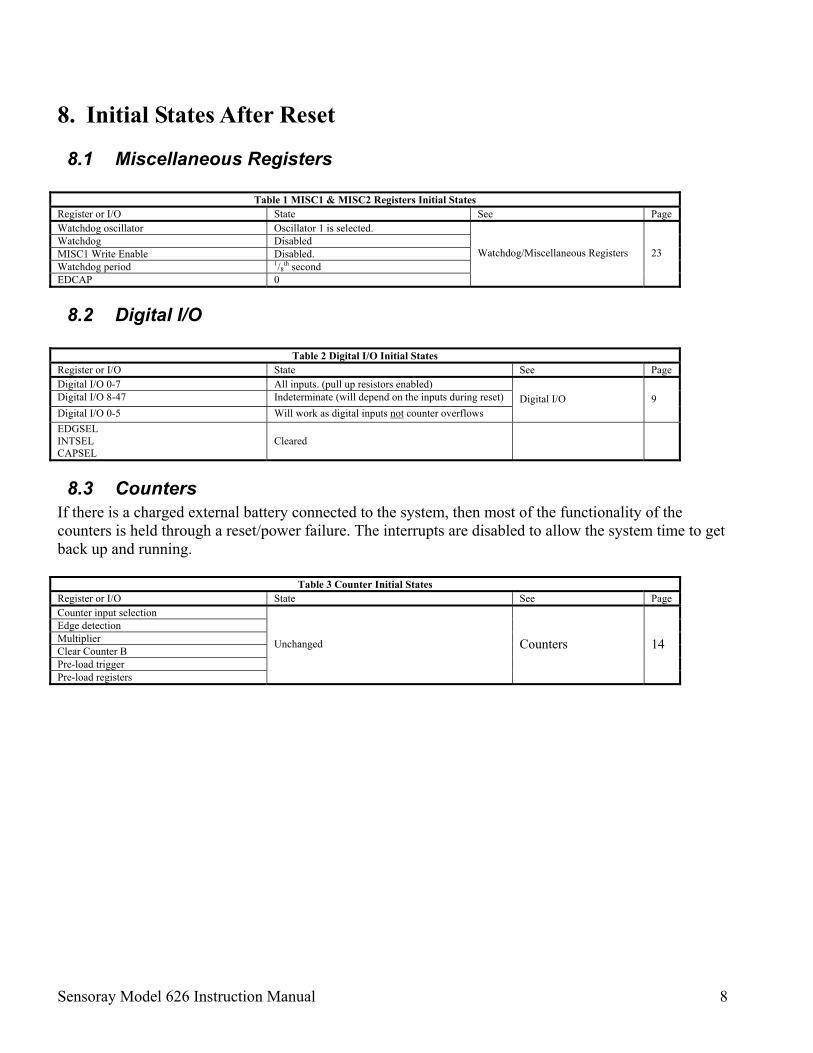
Table 1 MISC1 & MISC2 Registers Initial States Register or I/O State See Page Watchdog oscillator Oscillator 1 is selected. Watchdog Disabled MISC1 Write Enable Disabled. Watchdog period 1/8
th second EDCAP 0
Watchdog/Miscellaneous Registers 23
8.2 Digital I/O
Table 2 Digital I/O Initial States Register or I/O State See Page Digital I/O 0-7 All inputs. (pull up resistors enabled) Digital I/O 8-47 Indeterminate (will depend on the inputs during reset) Digital I/O 0-5 Will work as digital inputs not counter overflows
Digital I/O 9
EDGSEL INTSEL CAPSEL
Cleared
8.3 Counters If there is a charged external battery connected to the system, then most of the functionality of the counters is held through a reset/power failure. The interrupts are disabled to allow the system time to get back up and running.
Table 3 Counter Initial States Register or I/O State See Page Counter input selection Edge detection Multiplier Clear Counter B Pre-load trigger Pre-load registers
Unchanged Counters 14
Sensoray Model 626 Instruction Manual 9
9. Digital I/O
Figure 3 - Digital I/O Channels
9.1 Overview The 626 board provides 48 digital I/O channels. 40 of these channels (Channels 0-39) offer edge detection & interrupt on edge detection. Either a positive or negative edge can be detected. The other 8 channels (40-47) have simple input/output functionality only. Each channel can function as an input or an output. NOTE: Any channel that is to be used as an input must have a ‘0’ written to its output control register.
This ensures that the output transistor is turned off allowing the pull-up resistor to pull the channel high. If this is not done the transistor will have to sink high currents if the input is driven high externally.
48 DOUTA Write to Digital Output (0-15) 48 RDCAPFLGA Edges captured so far (0-15) 4A 4A RDINTSELA Status of interrupt enable register A 4C Not used 4C RDEDGSELA Status of edge selection register A 4E 4E RDCAPSELA Status of capture enable register A 50 50 52 WRINTSELB Interrupt Enable (16-31) 52 54 WREDGSELB Edge Selection (16-31) 54 56 WRCAPSELB Capture Enable (16-31) 56
DINB Status of digital inputs (16-31)
58 DOUTB Write to Digital Output (16-31) 58 RDCAPFLGB Edges captured so far (16-31) 5A 5A RDINTSELB Status of interrupt enable register B 5C Not used 5C RDEDGSELB Status of edge selection register B 5E 5E RDCAPSELB Status of capture enable register B 60 60 62 WRINTSELC Interrupt Enable (32-47) 62 64 WREDGSELC Edge Selection (32-47) 64 66 WRCAPSELC Capture Enable (32-47) 66
DINC Status of digital inputs (32-47)
68 DOUTC Write to Digital Output (32-47) 68 RDCAPFLGC Edges captured so far (32-47) 6A 6A RDINTSELC Status of interrupt enable register C 6C Not used 6C RDEDGSELC Status of edge selection register C 6E 6E RDCAPSELC Status of capture enable register C
Edge
Capture &
I/O Register
Inte
rrup
ts 1
48
InOut
InOut
Digital I/O
PCI B
us In
terf
ace
&
Con
trol L
ogic
Sensoray Model 626 Instruction Manual 10
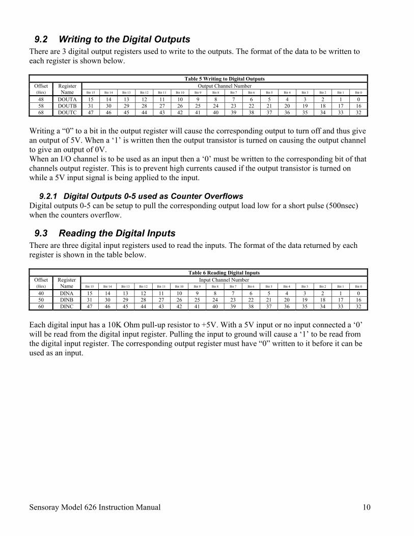
9.2 Writing to the Digital Outputs There are 3 digital output registers used to write to the outputs. The format of the data to be written to each register is shown below.
Table 5 Writing to Digital Outputs Offset Output Channel Number (Hex)
Register Name Bit 15 Bit 14 Bit 13 Bit 12 Bit 11 Bit 10 Bit 9 Bit 8 Bit 7 Bit 6 Bit 5 Bit 4 Bit 3 Bit 2 Bit 1 Bit 0
Writing a “0” to a bit in the output register will cause the corresponding output to turn off and thus give an output of 5V. When a ‘1’ is written then the output transistor is turned on causing the output channel to give an output of 0V. When an I/O channel is to be used as an input then a ‘0’ must be written to the corresponding bit of that channels output register. This is to prevent high currents caused if the output transistor is turned on while a 5V input signal is being applied to the input.
9.2.1 Digital Outputs 0-5 used as Counter Overflows Digital outputs 0-5 can be setup to pull the corresponding output load low for a short pulse (500nsec) when the counters overflow.
9.3 Reading the Digital Inputs There are three digital input registers used to read the inputs. The format of the data returned by each register is shown in the table below.
Table 6 Reading Digital Inputs Offset Input Channel Number (Hex)
Register Name Bit 15 Bit 14 Bit 13 Bit 12 Bit 11 Bit 10 Bit 9 Bit 8 Bit 7 Bit 6 Bit 5 Bit 4 Bit 3 Bit 2 Bit 1 Bit 0
Each digital input has a 10K Ohm pull-up resistor to +5V. With a 5V input or no input connected a ‘0’ will be read from the digital input register. Pulling the input to ground will cause a ‘1’ to be read from the digital input register. The corresponding output register must have “0” written to it before it can be used as an input.
Sensoray Model 626 Instruction Manual 11
9.4 Capture Digital Input Edges This feature is not available on inputs 20-23 and 44-47 (The grayed out areas of the tables). Reading any edge capture data or interrupt data from these inputs will always return 0. Writing to any of edge capture or interrupt register for these inputs will have no effect.
9.4.1 Selecting Positive or Negative Edge Capture
Table 7 Selecting Positive or Negative Edge Capture Offset Input Channel Number (Hex)
Register Name Bit 15 Bit 14 Bit 13 Bit 12 Bit 11 Bit 10 Bit 9 Bit 8 Bit 7 Bit 6 Bit 5 Bit 4 Bit 3 Bit 2 Bit 1 Bit 0
Write to the WREDSEL register with a ‘0’ to select negative edges (transition from 1 to 0) or a ‘1’ to select positive edges (transition from 0 to 1). Note that these will take effect once edge capturing for a particular channel has been enabled.
9.4.2 Edge Capture Interrupt A captured edge is usually set up to be accompanied by an interrupt. (See “Selecting Interrupt on Edge Capture” P13). If this is not done then the RDCAPFLG will need to be polled to see if an edge has occurred.
Before any edges can be captured the channel/s that are to be captured from must be enabled. Using the EDCAP bit of MISC1 to do this is a means of ‘masking out’ the other channel’s WRCAPSEL bits while modifying a selected channel. To Enable a channel for edge capture:
1. First the EDCAP bit of the MISC1 register must be setup. ‘1’ is used to enable one or more channels. ‘0’ is used to disable one or more channels.
2. Now write to the WRCAPSELA, B or C to apply the above command to the corresponding channels selected with a ‘1’ in WRCAPSELA, B or C.
Sensoray Model 626 Instruction Manual 12
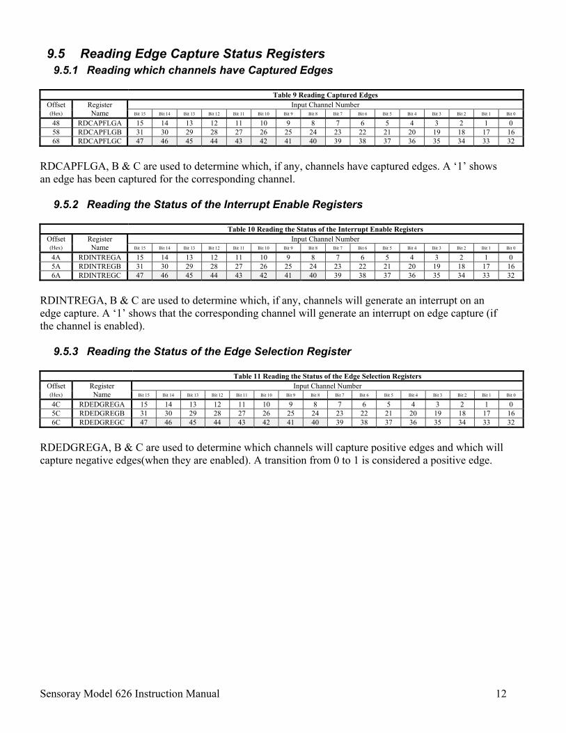
9.5 Reading Edge Capture Status Registers 9.5.1 Reading which channels have Captured Edges
Table 9 Reading Captured Edges
Offset Input Channel Number (Hex)
Register Name Bit 15 Bit 14 Bit 13 Bit 12 Bit 11 Bit 10 Bit 9 Bit 8 Bit 7 Bit 6 Bit 5 Bit 4 Bit 3 Bit 2 Bit 1 Bit 0
RDCAPFLGA, B & C are used to determine which, if any, channels have captured edges. A ‘1’ shows an edge has been captured for the corresponding channel.
9.5.2 Reading the Status of the Interrupt Enable Registers
Table 10 Reading the Status of the Interrupt Enable Registers Offset Input Channel Number (Hex)
Register Name Bit 15 Bit 14 Bit 13 Bit 12 Bit 11 Bit 10 Bit 9 Bit 8 Bit 7 Bit 6 Bit 5 Bit 4 Bit 3 Bit 2 Bit 1 Bit 0
RDINTREGA, B & C are used to determine which, if any, channels will generate an interrupt on an edge capture. A ‘1’ shows that the corresponding channel will generate an interrupt on edge capture (if the channel is enabled).
9.5.3 Reading the Status of the Edge Selection Register
Table 11 Reading the Status of the Edge Selection Registers Offset Input Channel Number (Hex)
Register Name Bit 15 Bit 14 Bit 13 Bit 12 Bit 11 Bit 10 Bit 9 Bit 8 Bit 7 Bit 6 Bit 5 Bit 4 Bit 3 Bit 2 Bit 1 Bit 0
RDEDGREGA, B & C are used to determine which channels will capture positive edges and which will capture negative edges(when they are enabled). A transition from 0 to 1 is considered a positive edge.
Sensoray Model 626 Instruction Manual 13
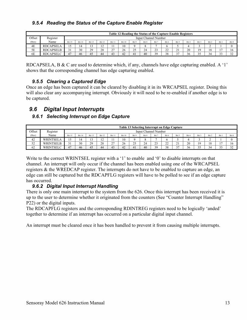
9.5.4 Reading the Status of the Capture Enable Register
Table 12 Reading the Status of the Capture Enable Registers Offset Input Channel Number (Hex)
Register Name Bit 15 Bit 14 Bit 13 Bit 12 Bit 11 Bit 10 Bit 9 Bit 8 Bit 7 Bit 6 Bit 5 Bit 4 Bit 3 Bit 2 Bit 1 Bit 0
RDCAPSELA, B & C are used to determine which, if any, channels have edge capturing enabled. A ‘1’ shows that the corresponding channel has edge capturing enabled.
9.5.5 Clearing a Captured Edge Once an edge has been captured it can be cleared by disabling it in its WRCAPSEL register. Doing this will also clear any accompanying interrupt. Obviously it will need to be re-enabled if another edge is to be captured.
9.6 Digital Input Interrupts 9.6.1 Selecting Interrupt on Edge Capture
Table 13 Selecting Interrupt on Edge Capture
Offset Input Channel Number (Hex)
Register Name Bit 15 Bit 14 Bit 13 Bit 12 Bit 11 Bit 10 Bit 9 Bit 8 Bit 7 Bit 6 Bit 5 Bit 4 Bit 3 Bit 2 Bit 1 Bit 0
Write to the correct WRINTSEL register with a ‘1’ to enable and ‘0’ to disable interrupts on that channel. An interrupt will only occur if the channel has been enabled using one of the WRCAPSEL registers & the WREDCAP register. The interrupts do not have to be enabled to capture an edge, an edge can still be captured but the RDCAPFLG registers will have to be polled to see if an edge capture has occurred.
9.6.2 Digital Input Interrupt Handling There is only one main interrupt to the system from the 626. Once this interrupt has been received it is up to the user to determine whether it originated from the counters (See “Counter Interrupt Handling” P22) or the digital inputs. The RDCAPFLG registers and the corresponding RDINTREG registers need to be logically ‘anded’ together to determine if an interrupt has occurred on a particular digital input channel. An interrupt must be cleared once it has been handled to prevent it from causing multiple interrupts.
Sensoray Model 626 Instruction Manual 14
10. Counters
10.1 Overview The Model 626 has six counters arranged in 3 pairs : 0A, 0B, 1A, 1B, 2A, and 2B. One of these pairs is shown in Figure 6 P17. They can be used in pairs or “stand alone”. Each counter can be used with the internal quadrature encoder interface for positioning systems, as timers using the internal clock, or as external (hardware) or internal (software) event counters. When paired a 48 bit counter can be achieved and development of functions like frequency counting is easy as one counter in the pair can feed the other either as a count, clear or latch input. The features include: • Counters can be completely software driven. • Counters can be driven from digital inputs 0-15. • Counters can be driven from the internal clock creating timers. • Counters can be driven from encoder inputs. • Encoder input buffers interface directly to TTL, CMOS, or differential RS422 signals • Quadrature decoder logic to detect and convert encoder edges into clock and direction signals. • Encoder quadrature multiplier (x1, x2, x4) • 24-bit up/down counters that can be pre-loaded by various triggers. • Counters can be read on the fly or captured by various triggers to be read later. • Selectable counter direction for timer and event counting modes. • Index input or overflow count can re-load counter with preset values. • Programmable interrupt on rollover or index pulse. • 5 Volt encoder power is available at encoder connector.
10.1.1 Latches From Figure 6 (Block diagram of a counter pair) it can be seen that there is 1 latch per pair of counters. Counter A or B can cause it’s own count to be latched on receiving an index pulse or an overflow from counter A can cause counter B’s count to be latched. These latches can be accompanied with an interrupt and the value captured in the latch can be read later. The latches can also be setup to latch as they are read. This allows the present value of the selected counter to be read.
10.1.2 Clear/Pre-load The system can be programmed so that an overflow from Counter A will clear counter B. This is useful for frequency counting where counter B is latched & cleared at an interval determined by the time it takes for counter A to overflow. Both counters can be programmed so that an index or overflow from a counter will pre-load itself with the contents of its pre-load register. This feature could be used to clear the counter by loading it with 0. This feature would be used for setting up a programmable interval timer. Both the clear & pre-load can be accompanied by an interrupt.
Sensoray Model 626 Instruction Manual 15
10.1.3 Interrupts Each counter can generate an interrupt on overflow, index or both.
10.1.4 Overflow Outputs The overflow output of each counter can be individually connected to a digital output. When the counter overflows a single pulse will occur pulling the output load low for 2 clock cycles (500nsec).
10.1.5 Index Inputs Each counter has a hardware or software controlled index input that can programmed to perform clear, pre-load or latch functions.
10.1.6 Counter Inputs Each counter has various input modes including: • Quadrature encoders with hardware or software controlled index. • Single ended event & direction & index inputs. • System clock with hardware or software control of direction & index for event timing. Each counter channel has two clock input phases (referred to as channels in this manual) named “A” and “B”. Depending on the application, one or both of these signals may be connected to an encoder or to a pulse source. If both phases are used, they are assumed to be quadrature encoded, meaning that they are 90 degrees out of phase. In this case, counters will count both up and down based on the timing relationship of the two-phase inputs. If only one phase is used, the input is said to be single-phase. In this case, counter channels will count either up or down for each pulse on the phase input depending on the polarity of the direction input. This configuration is typically used to count pulses from devices that produce a single clock output. Quadrature encoders for positioning systems have advantages over single-phase encoders. Counters will not accumulate errors when an encoder changes direction or dithers about a state transition boundary. Also, it is possible to increase encoder resolution by clocking the counters at a multiple of the single-phase clock rate.
10.1.7 Power failure If an external NiCad battery is connected and fully charged and the Battery Enable bit of MISC2 is set, then if power is lost, all the counter registers will be held and the counters will continue to operate even though the rest of the system is down. Note the counter interrupts are disabled when the system powers up but if an interrupt occurred during power down then it will occur the moment the interrupts are re-enabled.
Figure 4 Differential pair encoder. (Output with complement)
Figure 4 Single ended encoder. (TTL or CMOS)
Figure 5 Single ended event counter with external count direction & index control. (TTL or CMOS)
Note: If the counters are driven in a single ended mode as shown in Figure 4 and Figure 5, then the unused phase inputs do not have to be biased at 2.5V. Each encoder input has two 100K resistors that bias the input to 2.5V when no driving source is present.
Encoder A
B
A+
B+
A-
B-
VCCGND GND
+5V
IndexI+ I-
626
Device
Out
Direction (+5V=Up, 0V=Down)
A+
B+
A-
B-
VCCGND GND
+5V
Index
I+I-
626 2.5V
EncoderA
B
A+
B+
A-
B-
VCCGND GND
+5V
IndexI+I-
626 2.5V
Sensoray Model 626 Instruction Manual 17
10.3 Block Diagram
Figure 6 - Block diagram of a counter pair
Counter A
Counter B
Input logic &
M
ultiplier
Encoder
Digital I/O
Internal clock
Software
control
Input logic&
M
ultiplier
Encoder
Digital I/O
Internal clock
Software
control
Count
Direction
Index
Pre-Load register A
Pre-Load register B
PCI Bus
Count A
Overflow
Overflow
A
Counter B
Counter B
Clear/Pre-load
Count
Direction
Index
Count B
Latch 1
Input A
In put B
Latch A
Clear/Pre-load
Overflow
Interrupt C
apture R
egister B
InterruptC
aptureR
egisterA
Combined Counter Interrupts
From other counter interrupts
From other counter interrupts
Latch B
Sensoray Model 626 Instruction Manual 18
10.4 Counter Setup Registers
Table 15 CR0A 00 (hex) Read/Write Bit 15 Bit 14 Bit 13 Bit 12 Bit 11 Bit 10 Bit 9 Bit 8 Bit 7
Counter B index source Counter B source Counter A Index edge selection Counter A pre-load trigger source Counter A multiplier 00=Encoder 01=Digital inputs 10= Controlled by bit 1 of CR1B 11= Index disabled
00=Encoder 01=Digital inputs 10=Up Count with System clock 11=Down count with System clock (10 & 11 gated by bit 1 of CR1B)
0=Positive 1=Negative (Also used for software control of Counter A Index, 1=index)
00=Counter A index pulse 01=Counter A overflow 10=Disabled 11=Disabled
00=4x 01=2x 10=1x 11=Channel A is directionIndex is count pulse
Bit 6 Bit 5 Bit 4 Bit 3 Bit 2 Bit 1 Bit 0
Counter A interrupt source Counter A source edge selection Counter A Index source Counter A source 00=None 01=Overflow only 10=Index only 11=Index & Overflow
0=Positive 1=Negative Also software control of Counter A count pulse. 1=enable when running with the system clock.
00=Encoder 01=Digital inputs 10= Controlled by CR1A bit11 11= Index disabled
00=Encoder 01=Digital inputs 10= System clock up (gated by bit4) 11= System clock down (gated by bit4)
Table 16 CR0B 02 (hex) Read/Write
Bit 15 Bit 14 Bit 13 Bit 12 Bit 11 Bit 10 Bit 9 Bit 8
Clear Interrupt Select Interrupt B Select interrupt A Counter A Enable Counter B interrupt source Latch source 1=Clear Used with bit 13 or 14
1=Selected Used with bit 15
1=Selected Used with bit 15
0=Enabled 1=Only enabled if index A is high
00=None 01=Overflow only 10=Index only 11=Index & Overflow
00=Depends on latch read address 01=A’s index latches A 10=B’s index latches B 11=Counter A overflow captures B
Bit 7 Bit 6 Bit 5 Bit 4 Bit 3 Bit 2 Bit 1 Bit 0
Counter B pre-load trigger source
Clear Counter B Counter B multiplier Counter B Enable Counter B index edge selection
Counter B source edge selection
00=Counter B index pulse 01=Counter B overflow 10= Counter A overflow 11=Disabled
1=Counter A overflow clears Counter B 0=Not Cleared
00=4x 01=2x 10=1x 11=Channel A is direction Counter A overflow is count pulse
0=Enabled 1=Only enabled if index B is high
0=Positive 1=Negative (Also software control of Counter B Index, 1=index)
0=Positive 1=Negative Also software control of Counter B count pulse. 1=enable when running with the system clock.
The grayed bits read back different information to that which was written to them. (See “Table 17 CR0B 02 (hex) Read” below).
Table 17 CR0B 02 (hex) Read
Bit 15 Bit 14 Bit 13
Counter B Direction 0=Down 1=Up
1=Counter A overflow routed to digital output
1=Counter B overflow routed to digital output
In the following examples groups of bits will be referred to using their name and set to a binary value. For example ‘Counter B Multiplier’=10 means bit 4 =1 and bit 3=0. ‘X’ is used to show the value of a bit in one of the counter registers that is not important to the example being discussed. This is not to say it should be ignored. The value of these bits will depend on other functions being used and writing to any bit in the configuration example will always have an effect. Some bits have dual functions depending on the present settings of other bits. Many of the counter examples will only deal with counter 0A. Unless otherwise stated the function being discussed can also be applied to counter 0B. The correct register & bit/s just need to be used by looking at the applicable tables. Counters 1A, 1B, 2A & 2B will function in the same way just controlled using different register addresses. Do not be confused by the naming of registers CR0A & CR0B. They are simply the A & B parts of the single register CR0 (Counter Register 0) and do not refer specifically to counter A and counter B.
Counters 1 & 2 have the same register layout but with different Read/Write addresses.
Sensoray Model 626 Instruction Manual 19
10.5 Setting Up the Counter Source Counter A & counter B can be driven by a differential or single ended encoder, the digital inputs, software or from the system clock. Each counter’s input logic has a count, direction & index line that can be controlled. The ‘Counter A Source’ bits are used to select counter A’s source. (See Table 15 & Table 16 P18) If ‘Counter A Source’=00 then encoder inputs are selected. If ‘Counter A Source’=01 then the digital inputs control the counters.
Table 18 Digital inputs as Counter input controls Digital Input Channel Counter Counter Input Function
1 0 A Count or direction input 2 0 A Count input 3 0 A Index input 4 0 B Count or direction input 5 0 B Count input 6 0 B Index input 7 1 A Count or direction input 8 1 A Count input 9 1 A Index input
10 1 B Count or direction input 11 1 B Count input 12 1 B Index input 13 2 A Count or direction input 14 2 A Count input 15 2 A Index input 16 2 B Count or direction input 17 2 B Count input 18 2 B Index input
When the digital inputs are selected as the source then the corresponding digital inputs can be used to control the counters in much the same way as when the encoder inputs are used. This mode also gives software control of the counters. This is achieved by writing to the corresponding digital output that in tern will change the digital input and thus the counter. The disadvantage to doing this is the fact that the digital output is now used for counter control & cannot be used for normal I/O functions. In mode 00 & 10 above, the ‘Counter A Source Edge Selection’ is used to select positive ‘0’ or negative ‘1’ edge selection. If ‘Counter A Source’ =10 then the counter will count down with the system clock. If ‘Counter A Source’ =11 then the counter will count up with the system clock. In both these modes the ‘Counter A Multiplier’ must be 10 and ‘Counter A Source Edge Selection’ must be 1. These two bits become part of the oscillator feedback loop. ‘Counter A Source Edge Selection’ could be used as an enable. The timer will only run when it is ’1’. ‘Counter A Enable’ is used to gate the counter under normal counting operation. When cleared counting is enabled and when set counting is disabled. When using software to control counter A, ‘Counter A Enable’ must be ‘1’ to enable counting. The ‘Counter A Index Source’ bits are used to select counter A’s index source. If ‘Counter A Index Source’=00 then the encoder index input will control indexing. If ‘Counter A Index Source’=01 then the digital inputs control the indexing. While in this mode ‘Counter A Index Edge Selection’=0 will index on the positive edges while 1 will index on the negative edges.
Sensoray Model 626 Instruction Manual 20
10.5.1 Software Control of the Index If ‘Counter A Index Source’=10 or 11 then an index is caused by toggling the ‘Counter A Index Edge Selection’ bit. When this kind of software control of the index pulse is needed it is recommended that the ‘Counter A Index Source’ is set to 10. Then setting ‘Counter A Index Edge Selection’ will set the index input to the counter & clearing it will clear the index input to the counter. If the ‘Counter A Index Source’ be set to 11 then setting ‘Counter A Index Edge Selection’ will clear the index input to the counter & clearing it will set the index input to the counter.
10.5.2 Multiplier The ‘Counter A Multiplier’ bits are used to multiply counter A’s incoming pulses by 1, 2 or 4 or to allow software count control. The ‘Counter B Multiplier’ bits are used to multiply counter B’s incoming pulses by 1, 2 or 4 or to allow an overflow from counter A to cause counter B to count 1. The multiplying feature is only used when the encoder or digital inputs are used to drive the counters. If only a count and direction input is being used then the multiplier should be 1x or 2x. Channel A is the direction & channel B the count.
10.5.3 Software Control Of Direction & Count Generation This mode is only available on counter A. Direction control & a count pulse can be generated completely under software control for counter A. This mode uses the counters index interface to generate the count pulse. As a result, while in this mode, the index cannot cause an interrupt, a latch or a pre-load of counter A. To place counter A in this mode ‘Counter A Enable’ must be 1 and ‘Counter A Multiplier’ must be 11. Channel A & B combined, of counter A will now control the count direction. They can be connected to the channel A encoder inputs, the channel A digital inputs or can be software controlled. To use software control for the direction, ‘Counter A Edge Selection’ must be 0. To set the count direction down ‘Counter A Source’ must be 10. To set the count direction up ‘Counter A Source’ must be 11. When using the encoder or digital inputs then channel A & B must be connected in parallel to form a single direction control. The index channel of counter A will control the counting. It can be connected using the encoder index channel, the digital input index pin or it can be software controlled. To use software control for the count pulse, it is recommended that the ‘Counter A Index Source’ be set to 10. Then setting ‘Counter A Index Edge Selection’ will set the index input & clearing it will clear the index input, thus creating a count pulse. If the ‘Counter A Index Source’ is set to 11 then setting ‘Counter A Index Edge Selection’ will clear the index input & clearing it will set the index input also creating a count.
10.6 Driving Counter B From Counter A’s Overflow This mode is only available on Counter B. Counter B can be setup so that it will count every time counter A overflows. To do this ‘Counter B Multiplier’ must be 11, which will cause the count input to counter B to come from counter A’s overflow. Channel A of counter B will now control the count direction. It can be connected to the channel A encoder input, the channel A digital input or it can be software controlled. To use software control for the direction, ‘Counter B Source Edge Selection’ must be 0. To set the count direction to down ‘Counter B Source’ must be 11. To set the count direction to up ‘Counter B Source’ must be 10.
Sensoray Model 626 Instruction Manual 21
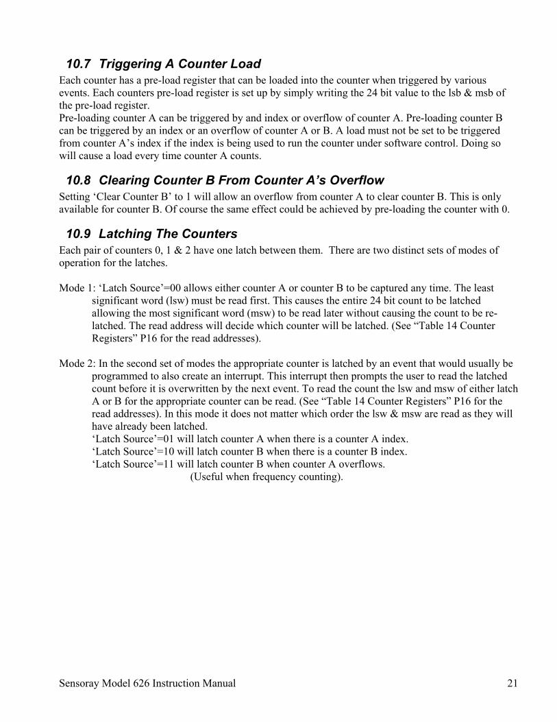
10.7 Triggering A Counter Load Each counter has a pre-load register that can be loaded into the counter when triggered by various events. Each counters pre-load register is set up by simply writing the 24 bit value to the lsb & msb of the pre-load register. Pre-loading counter A can be triggered by and index or overflow of counter A. Pre-loading counter B can be triggered by an index or an overflow of counter A or B. A load must not be set to be triggered from counter A’s index if the index is being used to run the counter under software control. Doing so will cause a load every time counter A counts.
10.8 Clearing Counter B From Counter A’s Overflow Setting ‘Clear Counter B’ to 1 will allow an overflow from counter A to clear counter B. This is only available for counter B. Of course the same effect could be achieved by pre-loading the counter with 0.
10.9 Latching The Counters Each pair of counters 0, 1 & 2 have one latch between them. There are two distinct sets of modes of operation for the latches. Mode 1: ‘Latch Source’=00 allows either counter A or counter B to be captured any time. The least
significant word (lsw) must be read first. This causes the entire 24 bit count to be latched allowing the most significant word (msw) to be read later without causing the count to be re-latched. The read address will decide which counter will be latched. (See “Table 14 Counter Registers” P16 for the read addresses).
Mode 2: In the second set of modes the appropriate counter is latched by an event that would usually be
programmed to also create an interrupt. This interrupt then prompts the user to read the latched count before it is overwritten by the next event. To read the count the lsw and msw of either latch A or B for the appropriate counter can be read. (See “Table 14 Counter Registers” P16 for the read addresses). In this mode it does not matter which order the lsw & msw are read as they will have already been latched. ‘Latch Source’=01 will latch counter A when there is a counter A index. ‘Latch Source’=10 will latch counter B when there is a counter B index. ‘Latch Source’=11 will latch counter B when counter A overflows.
(Useful when frequency counting).
Sensoray Model 626 Instruction Manual 22
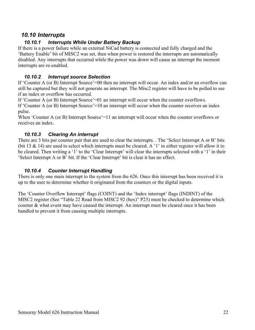
10.10 Interrupts 10.10.1 Interrupts While Under Battery Backup
If there is a power failure while an external NiCad battery is connected and fully charged and the ‘Battery Enable’ bit of MISC2 was set, then when power is restored the interrupts are automatically disabled. Any interrupts that occurred while the power was down will cause an interrupt the moment interrupts are re-enabled.
10.10.2 Interrupt source Selection If ‘Counter A (or B) Interrupt Source’=00 then no interrupt will occur. An index and/or an overflow can still be captured but they will not generate an interrupt. The Misc2 register will have to be polled to see if an index or overflow has occurred. If ‘Counter A (or B) Interrupt Source’=01 an interrupt will occur when the counter overflows. If ‘Counter A (or B) Interrupt Source’=10 an interrupt will occur when the counter receives an index pulse. When ‘Counter A (or B) Interrupt Source’=11 an interrupt will occur when the counter overflows or receives an index.
10.10.3 Clearing An interrupt There are 3 bits per counter pair that are used to clear the interrupts. . The ‘Select Interrupt A or B’ bits (bit 13 & 14) are used to select which interrupts must be cleared. A ‘1’ in either register will allow it to be cleared. Then writing a ‘1’ to the ‘Clear Interrupt’ will clear the interrupts selected with a ‘1’ in their ‘Select Interrupt A or B’ bit. If the ‘Clear Interrupt’ bit is clear it has no effect.
10.10.4 Counter Interrupt Handling There is only one main interrupt to the system from the 626. Once this interrupt has been received it is up to the user to determine whether it originated from the counters or the digital inputs. The ‘Counter Overflow Interrupt’ flags (COINT) and the ‘Index interrupt’ flags (INDINT) of the MISC2 register (See “Table 22 Read from MISC2 92 (hex)” P23) must be checked to determine which counter & what event may have caused the interrupt. An interrupt must be cleared once it has been handled to prevent it from causing multiple interrupts.
Sensoray Model 626 Instruction Manual 23
11. Watchdog/Miscellaneous Registers
Table 19 Write to MISC1 88 (hex) Bit 15 Bit 14 Bit 13 Bit 12 Bit 11 Bit 10 Bit 9 Bit 8
1=Write enable Not used Not used EDCAP (See P 11)
Not Used Not Used
Not Used
Not Used
Bit 7 Bit 6 Bit 5 Bit 4 Bit 3 Bit 2 Bit 1 Bit 0
Not Used Not Used Not Used Not Used Not Used Not Used Not Used Not Used
Table 20 Read from MISC1 88 (hex)
Bit 15 Bit 14 Bit 13 Bit 12 Bit 11 Bit 10 Bit 9 Bit 8
The grayed bits do not read back the same registers.
11.1 Battery Charging Bit 14 “Charge Enable” of MISC2 (92 hex) turns the trickle charging of an optional external backup battery on and off. The system will default to “Charging off” after a reset. Before writing to any of the bits of MISC2, except bit 15 (Clear watchdog), the write enable (bit 15) of MISC1 must be set. This is to prevent accidental modification of the watchdog settings by a crashed CPU. It is a good idea to clear this bit immediately after writing to MISC2.
Sensoray Model 626 Instruction Manual 24
11.2 Watchdog Oscillator 11.2.1 Overview
Embedded systems often include a watchdog timer to regain program control following an unplanned loss of control by the PCI bus master. In such systems, the CPU is responsible for periodically clearing the watchdog timer. Should the CPU crash, the watchdog won't be cleared and will eventually overflow and cause the CPU to be reset through the PCI bus. After a reset the watchdog timer is disabled and the watchdog oscillator selection is cleared. To use the watchdog, it needs to be enabled and the watchdog period needs to be set. Any external hardware also may be reset by the watchdog timer with the additional relay. This relay has one switched contact group insulated from internal circuit.
11.2.2 Testing the Watchdog Without Resetting the Host Under normal conditions a watchdog time-out will cause the PCI bus to be reset. By removing jumper JP1 no PCI reset will occur although the watchdog will be fully functional internally. This may be useful during development as the status of the watchdog can be obtained from bit 14 of Misc1. A ‘1’ means it has timed out. The watchdog output at JP1 is an ‘open collector’ output. The relay watchdog output may be disabled by removing jumper J10.
11.2.3 Watchdog Enable & Period Selection Bits 1 & 0 of MISC2 (92 hex) are used to select a period of 1/8, 1/2, 1 or 10 seconds while bit 2 is used to enable the watchdog. (See “Table 21 Write to MISC2 90 (hex)” P23). Before writing to any of the bits of MISC2, except bit 15 (Clear watchdog), the write enable (bit 15) of MISC1 must be set. This is to prevent accidental modification of the watchdog settings by a crashed CPU. It is a good idea to clear this bit immediately after writing to MISC2. Although the Enable and period selection bits are in the same register, first the register must be written to with the ‘Watchdog Enable’ bit = ‘1’ (bit 2) and then the register must be written to again with bit 2 again = ‘1’ and the period selection bits set as desired. This is because the period selection bits are held in a cleared state (1/8
th of a second) and cannot be changed until the ‘Watchdog enable’ bit is = ‘1’.
11.2.4 Clearing the Watchdog To prevent a PCI reset the watchdog timer must be cleared at least once within the period of the watchdog timer. To do this bit 15 (“Write Enable”) of MISC1 (88 hex) must first be cleared and then bit 15 (Clear watchdog) of MISC2 (92 hex) must be set. The clear watchdog bit is automatically cleared after the watchdog has been cleared.
11.2.5 Watchdog LED Status If the watchdog is disabled the red LED will be off continuously. When the watchdog is enabled the LED will be off for ½ the selected watchdog period, then on for ½ the period and then the watchdog will reset the PCI bus (Pulled low) if JP1 is inserted or if the jumper is not inserted then bit 14 of Misc2 will go high and the LED will flash at ½ the selected watchdog period.
Sensoray Model 626 Instruction Manual 25
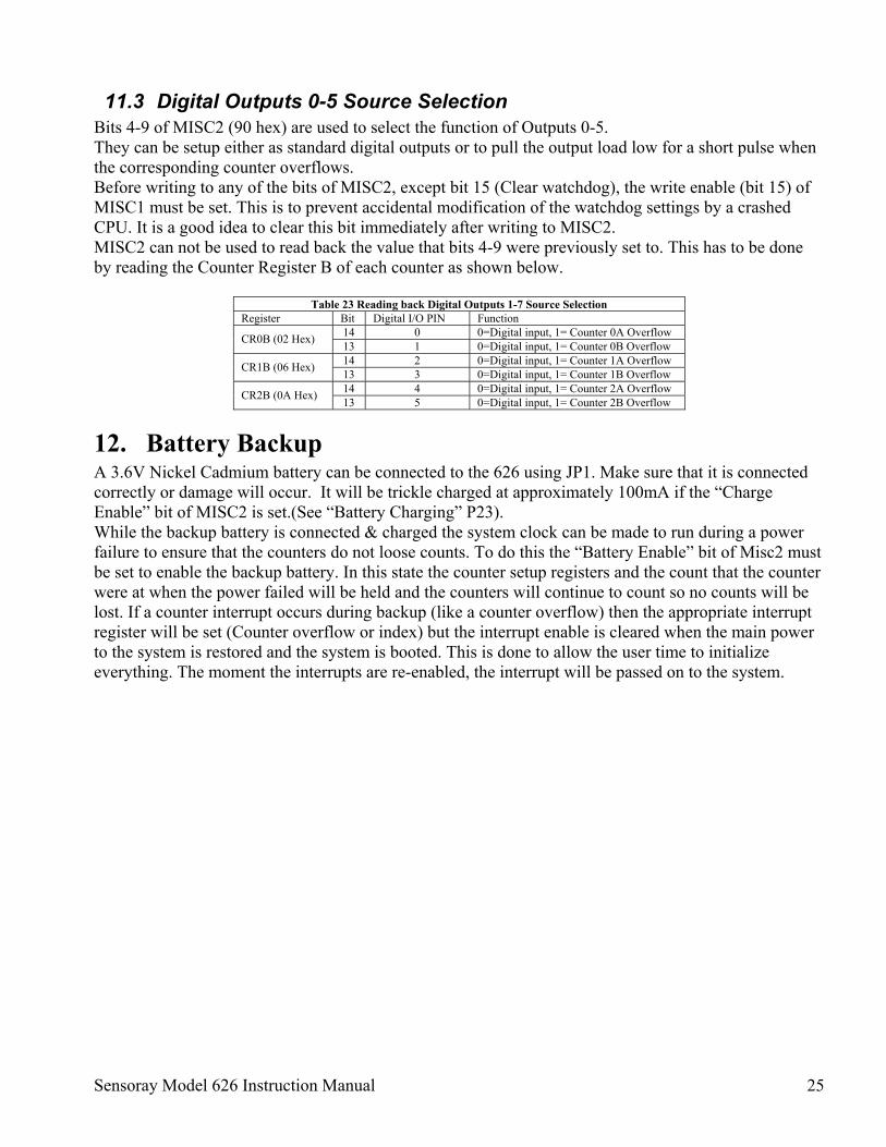
11.3 Digital Outputs 0-5 Source Selection Bits 4-9 of MISC2 (90 hex) are used to select the function of Outputs 0-5. They can be setup either as standard digital outputs or to pull the output load low for a short pulse when the corresponding counter overflows. Before writing to any of the bits of MISC2, except bit 15 (Clear watchdog), the write enable (bit 15) of MISC1 must be set. This is to prevent accidental modification of the watchdog settings by a crashed CPU. It is a good idea to clear this bit immediately after writing to MISC2. MISC2 can not be used to read back the value that bits 4-9 were previously set to. This has to be done by reading the Counter Register B of each counter as shown below.
Table 23 Reading back Digital Outputs 1-7 Source Selection Register Bit Digital I/O PIN Function
12. Battery Backup A 3.6V Nickel Cadmium battery can be connected to the 626 using JP1. Make sure that it is connected correctly or damage will occur. It will be trickle charged at approximately 100mA if the “Charge Enable” bit of MISC2 is set.(See “Battery Charging” P23). While the backup battery is connected & charged the system clock can be made to run during a power failure to ensure that the counters do not loose counts. To do this the “Battery Enable” bit of Misc2 must be set to enable the backup battery. In this state the counter setup registers and the count that the counter were at when the power failed will be held and the counters will continue to count so no counts will be lost. If a counter interrupt occurs during backup (like a counter overflow) then the appropriate interrupt register will be set (Counter overflow or index) but the interrupt enable is cleared when the main power to the system is restored and the system is booted. This is done to allow the user time to initialize everything. The moment the interrupts are re-enabled, the interrupt will be passed on to the system.
Sensoray Model 626 Instruction Manual 26
13. Analog Inputs There are 16 analog input channels (0-15). Each channel can be set to have a ±5V or ±10V range, which will return a 16 bit value (including the sign) in the range ±32767. A ‘Poll List’ is used to setup the A/D converter. This is a list containing 1-16 commands that will be executed sequentially every time the ReadADC command is used. Each command tells the converter which channel to convert (0-15) and what range to use (±5V or ±10V). The converter starts with the first command in the list and continues until it reaches a command with a ‘1’ in bit 15 of the command or until the 16th command is executed. The results are placed in the array Data[0..15]. If the same set of channel & range combinations need to be read again the user needs only to execute another ReadADC command and the old Data will be overwritten with the new. When a new poll list needs to be set up, the CloseADC command needs to be executed to close the old list and then the ResetADC needs to be executed with the details of the new poll list. This poll list approach makes reading several channels much faster. Conversion takes approximately 20usec/channel. Once completely finished with the ADC the CloseADC command should be executed.
14. Analog Outputs The analog channels have a 14 bit resolution (including sign). It takes approximately 200µS to convert the digital value to an analog output voltage. To use the Digital to Analog converter call the WriteDAC function and supply a channel and an output value between –8191 and +8191. This will be converted to an analog voltage between ±10V at the specified output channel. Each D/A has a sense input that should be connected to the D/A output at the end of the wire used to connect to whatever external circuit is used with the D/A. This will help keep noise down. If this feature is not used then insert the jumpers which in effect connects the sense input to the D/A output right on the board. J6, J7, J8 & J9 are inserted to disable the sense inputs for channels 0 -3 respectively.
Sensoray Model 626 Instruction Manual 27
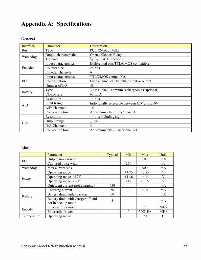
Appendix A: Specifications
General
Interface Parameter Description Bus Type PCI, 32-bit, 33MHz
Output characteristics Open collector, Relay Watchdog Timeout 1/8, 1/2, 1 & 10 seconds Input characteristics Differential pair/TTL/CMOS compatible Counter size 24 bits Encoders Encoder channels 6 Input characteristics TTL/CMOS compatible. Configuration Each channel can be either input or output I/O Number of I/O 48 Type 3.6V Nickel Cadmium rechargeable (Optional) Battery Charge rate 62.5mA Resolution 14 bits Input Range Individually selectable between ±5V and ±10V A/D Channels 16
A/D
Conversion time Approximately 20usec/channel Resolution 14 bits including sign Output range ±10V D/A Channels 4
D/A
Conversion time Approximately 200usec/channel
Limits
Parameter Typical Min Max Units Output sink current 100 mA I/O Captured pulse width 250 ns
Watchdog Max current sink 500 mA Operating range +4.75 +5.25 V Operating range +12V +11.6 +15 V Operating range -12V -15 -11.6 V Power
Quiescent current (not charging) 450 mA Charging current 50 0 62.5 mA Battery drain under backup 60 mA Battery Battery drain with charger off and not in backup mode 5 mA
Internal timer mode 2 MHz Encoder Externally driven 0 500KHz MHz Temperature Operating range 0 70 C


![Dies Irae - Requiem in D Minor K. 626 [K. 626]](https://static.documents.pub/doc/80x56/616e2e726c1eb666d037d848/dies-irae-requiem-in-d-minor-k-626-k-626.jpg)


