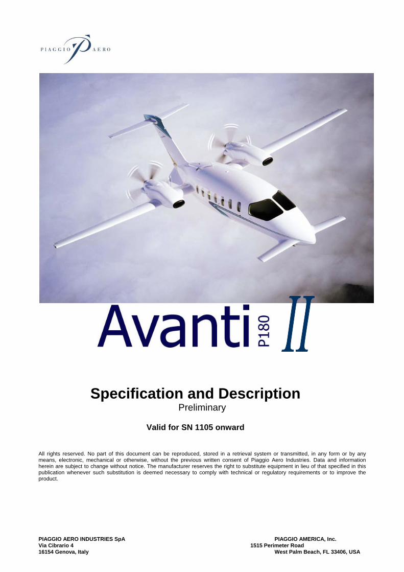
PIAGGIO AERO INDUSTRIES SpA PIAGGIO AMERICA, Inc. Via Cibrario 4 1515 Perimeter Road 16154 Genova, Italy West Palm Beach, FL 33406, USA Specification and Description Preliminary Valid for SN 1105 onward All rights reserved. No part of this document can be reproduced, stored in a retrieval system or transmitted, in any form or by any means, electronic, mechanical or otherwise, without the previous written consent of Piaggio Aero Industries. Data and information herein are subject to change without notice. The manufacturer reserves the right to substitute equipment in lieu of that specified in this publication whenever such substitution is deemed necessary to comply with technical or regulatory requirements or to improve the product.
Transcript
PIAGGIO AERO INDUSTRIES SpA PIAGGIO AMERICA, Inc. Via Cibrario 4 1515 Perimeter Road 16154 Genova, Italy West Palm Beach, FL 33406, USA
Specification and Description Preliminary
Valid for SN 1105 onward
All rights reserved. No part of this document can be reproduced, stored in a retrieval system or transmitted, in any form or by any means, electronic, mechanical or otherwise, without the previous written consent of Piaggio Aero Industries. Data and information herein are subject to change without notice. The manufacturer reserves the right to substitute equipment in lieu of that specified in this publication whenever such substitution is deemed necessary to comply with technical or regulatory requirements or to improve the product.
Specification and Description
Preliminary
Valid for SN 1105 onward
File P180Avanti II Spec&Option-1-R2.doc Revision 5.0 Preliminary Date : January 2005 Page 1
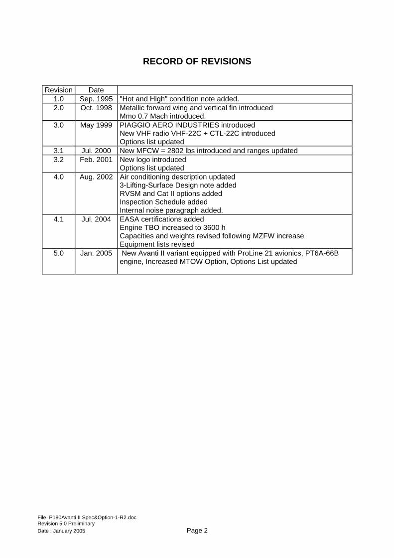
RECORD OF REVISIONS
Revision Date 1.0 Sep. 1995 "Hot and High" condition note added. 2.0 Oct. 1998 Metallic forward wing and vertical fin introduced
New VHF radio VHF-22C + CTL-22C introduced Options list updated
3.1 Jul. 2000 New MFCW = 2802 lbs introduced and ranges updated 3.2 Feb. 2001 New logo introduced
Options list updated 4.0 Aug. 2002 Air conditioning description updated
3-Lifting-Surface Design note added RVSM and Cat II options added Inspection Schedule added Internal noise paragraph added.
4.1 Jul. 2004 EASA certifications added Engine TBO increased to 3600 h Capacities and weights revised following MZFW increase Equipment lists revised
5.0 Jan. 2005 New Avanti II variant equipped with ProLine 21 avionics, PT6A-66B engine, Increased MTOW Option, Options List updated
File P180Avanti II Spec&Option-1-R2.doc Revision 5.0 Preliminary Date : January 2005 Page 2
INTRODUCTION
This document aims to provide a general information to evaluate the design, performance, and equipment of the PIAGGIO P.180 Avanti II Aircraft. For further details you are kindly requested to contact: PIAGGIO AERO INDUSTRIES S.p.A. Sales and Marketing Via Cibrario, 4 16154 GENOVA SESTRI (Italy) tel.: + 39 010 6481 1 (Switchboard) fax: + 30 010 6481 309 e-mail: [email protected] www.piaggioaero.com PIAGGIO AMERICA, Inc. Sales & Marketing 1515 Perimeter Rd. West Palm Beach, FL 33406, USA Phone 001 561 253 0104 Fax 001 561 253 0238 e-mail: [email protected]
File P180Avanti II Spec&Option-1-R2.doc Revision 5.0 Preliminary
www.piaggioamerica.com This document supersedes all the previously edited Specification and Description documents and describes only the PIAGGIO P.180 Avanti II’s powerplant and equipment.
Warranties applicable to the P.180 Avanti II are also included. In case of conflict or discrepancy between this document and the basic purchase agreement to which it may be enclosed, terms specified in the basic purchase agreement shall govern. Reference to manufacturers of parts and equipment herein are quoted just as general reference, and are therefore subject to change. Specifications, Standard Equipment and Suppliers are subject to change without notice. All performance information herein concerns the Standard Aircraft before installing any optional equipment. All diagrams and schemes are for illustrative purpose only. This document may not be reproduced, either in part or in whole, without the permission of PIAGGIO AERO INDUSTRIES S.p.A. All reasonable care has been taken by PIAGGIO AERO INDUSTRIES S.p.A. to ensure the accuracy of the information contained in this document. However, this document neither constitutes a contractual commitment, nor is to be used in connection with the flight operation or maintenance of an aircraft.
3 AIRFRAME 14 3.1 Fuselage group 14 3.2 Wing group 14 3.3 Empennage group 15 3.4 Landing gear 15 3.5 Powerplants 16
4 SYSTEMS 17 4.1 Flight controls 17 4.2 Fuel system 18 4.3 Hydraulic system 18 4.4 Electrical system 19 4.5 Lights 19 4.6 Pressurisation and environmental system 19 4.7 Oxygen system 20 4.8 Ice protection 20
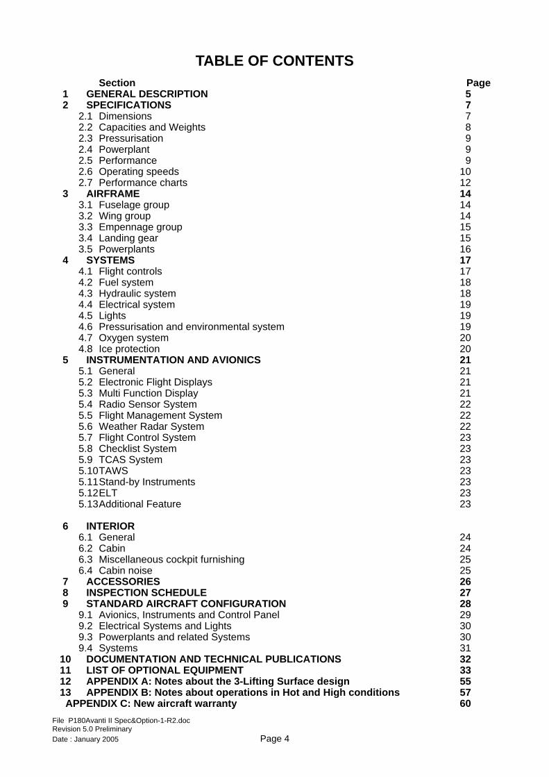
5 INSTRUMENTATION AND AVIONICS 21 5.1 General 21 5.2 Electronic Flight Displays 21 5.3 Multi Function Display 21 5.4 Radio Sensor System 22 5.5 Flight Management System 22 5.6 Weather Radar System 22 5.7 Flight Control System 23 5.8 Checklist System 23 5.9 TCAS System 23 5.10 TAWS 23 5.11 Stand-by Instruments 23 5.12 ELT 23 5.13 Additional Feature 23
9.1 Avionics, Instruments and Control Panel 29 9.2 Electrical Systems and Lights 30 9.3 Powerplants and related Systems 30 9.4 Systems 31
10 DOCUMENTATION AND TECHNICAL PUBLICATIONS 32 11 LIST OF OPTIONAL EQUIPMENT 33 12 APPENDIX A: Notes about the 3-Lifting Surface design 55 13 APPENDIX B: Notes about operations in Hot and High conditions 57
APPENDIX C: New aircraft warranty 60 File P180Avanti II Spec&Option-1-R2.doc Revision 5.0 Preliminary Date : January 2005 Page 4
1. GENERAL DESCRIPTION
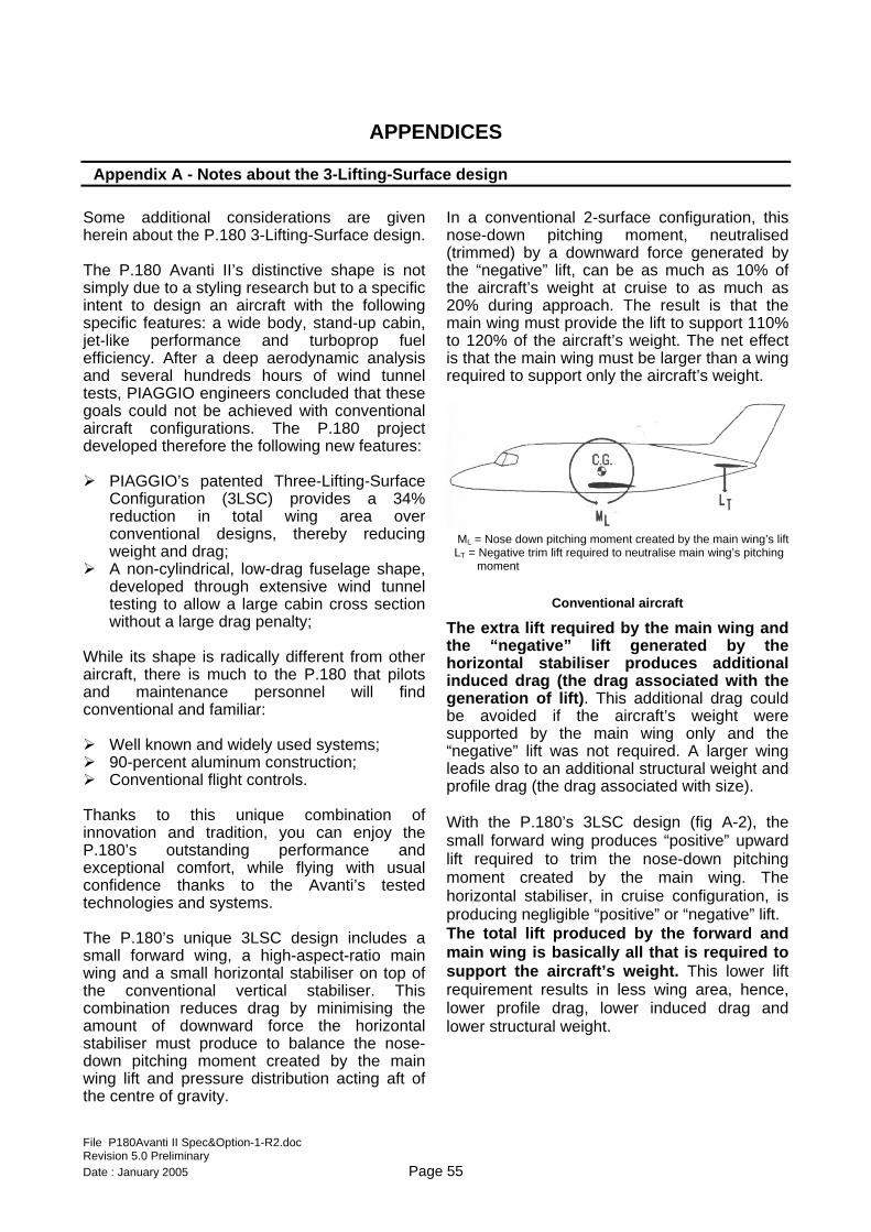
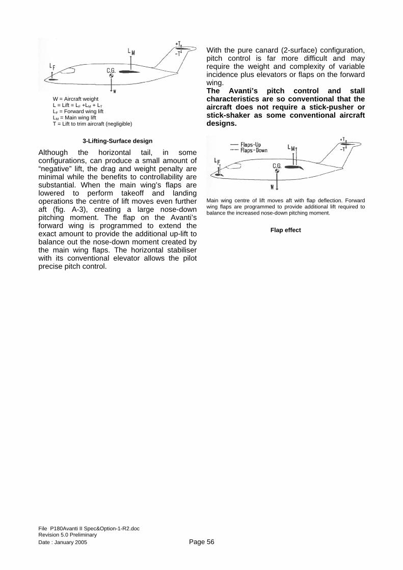
The PIAGGIO P.180 Avanti II is a pressurised, twin-engine, three lifting surfaces, pusher propellers, turbine-powered aircraft capable of carrying up to 11 passengers (including crew). The aircraft complies with the requirements of EASA CS-23 and of F.A.R. Part 23. It has been certified by the Authorities of the European Union, United States and Canada in the transport category including day, night, VFR, IFR operations and flight into known icing conditions. The Avanti complies with RVSM operation requirements and is approved for Cat. II approach and landing operations and for steep approaches. The Avanti is designed to provide jet-like speed on turboprop fuel flows, as well as the spaciousness and comfort of a wide-body, stand-up cabin. Key to the Avanti's speed and efficiency is the three lifting surface configuration and no aerodynamic compromise. In collaboration with the Ohio State Aeronautical Laboratory and applying a NASA-developed methodology, a rear-loaded airfoil for the main wing was designed, taking advantage of the pusher configuration's undisturbed airflow over the main wing to enhance laminarity. Laminar flow over 50% of the wing chord was achieved, which compares to a maximum of 20% of wing chord normally obtained on tractor type propeller aircraft. The Avanti's forward wing (which is not a canard because it has no control surfaces) is a fixed lifting surface equipped with flaps synchronized with the main wing flaps. The forward wing pitch angle is set so it stalls before the main wing, producing an automatic nose-down effect and enhancing safety and controllability. A five-degree negative dihedral allows keeping the downwash clear of the engine inlets and of the main wing. The three lifting surfaces configuration of the Avanti results in a 34% reduction in the main wing
area, thus leading to a proportional benefit in weight and drag. Pitch and yaw control are carried out through a traditional T-tail arrangement and lateral control through ailerons, thus providing fully conventional handling characteristics. All controls are fully manual and aerodynamically balanced for lightness, and the ailerons have fully sealed gaps. All control surfaces have electrically - powered trim tabs. The airframe is mainly made up of aluminium alloy with a limited amount of composite construction. A variable cross-section, streamlined fuselage was developed to achieve both efficiency and a large interior space at the same time. The fuselage is a stressed skin structure made up of conventional aluminium alloy, produced through an innovative, "outside-in" construction process, whereby large skin panels are held in place by vacuum tools during riveting of the internal structure. The result is a fuselage built to extremely close external tolerances, thus minimising drag due to imperfections. Composite materials have been used only in those areas that require maximum stiffness with minimum weight, such as the horizontal stabiliser, and also in areas characterised by intricate compound curves such as the engine nacelles. The turboprop engines are equipped with inertial particle separators and installed in a pusher configuration in low-drag, area-ruled cowlings. The five-bladed counter rotating propellers are optimised to work in the airflow from the wing and engine exhaust and do not need any anti-ice system since they are naturally heated by the exhaust gases.
File P180Avanti II Spec&Option-1-R2.doc Revision 5.0 Preliminary Date : January 2005 Page 5
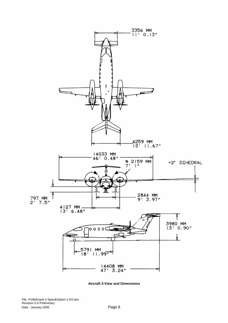
Aircraft 3-View and Dimensions
File P180Avanti II Spec&Option-1-R2.doc Revision 5.0 Preliminary Date : January 2005 Page 6
2. SPECIFICATIONS
2.1 Dimensions Wing
Span (without fairings) 45.41 ft 13.84 m Aspect Ratio 11.96 Sweep (leading edge) 1°11'24" Dihedral 2°00'00" Area 172.22 ft2 16.00 m2 Wing Loading 67.07 lb/ft2 327.40 kg/m2
Forward Wing Span (without fairings) 10.76 ft 3.28 m Aspect Ratio 4.92 Sweep (@ 25% chord) 0°00'00" Dihedral -5°00'00" Area 23.59 ft2 2.19 m2
Horizontal Tail Span (without fairings) 13.73 ft 4.18 m Aspect Ratio 4.57 Sweep (@ 25% chord) 29°48'00" Dihedral -5°00'00" Area 41.27 ft2 3.83 m2
Vertical Tail Span 7.70 ft 2.35 m Sweep (@ 25% chord) 40°00'00" Area 50.92 ft2 4.73 m2
External Dimensions Length 47 ft 3.2 in 14.41 m Height 13 ft 0.7 in 3.98 m Span 46 ft 0.5 in 14.03 m
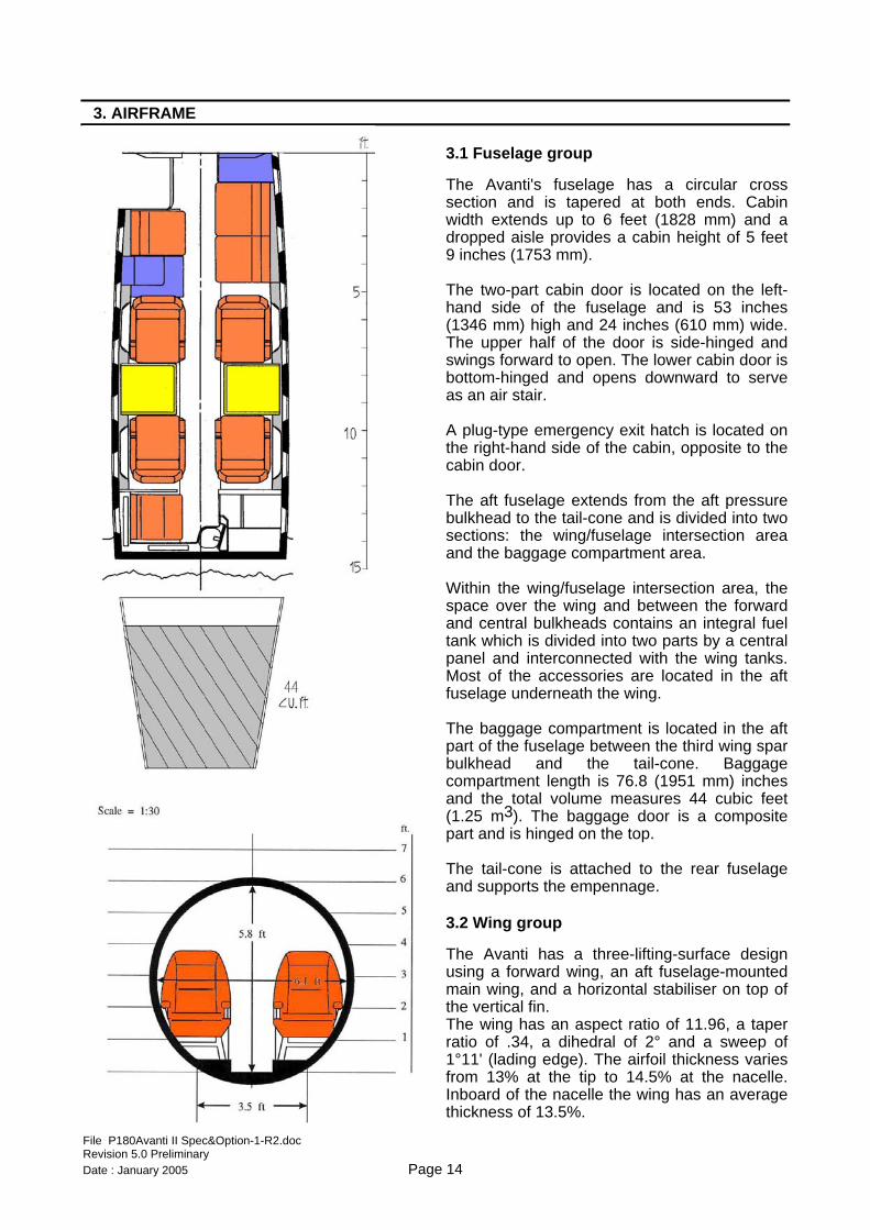
Cabin Dimensions Height 69 in 1.75 m Width 73 in 1.85 m Cockpit Length 57 in 1.45 m Passenger Cabin Length 179 in 4.55 m Lavatory Length 31 in 0.79 m Total Length 267 in 6.79 m
Baggage Compartment Dimensions Total Length 67 in 1.70 m
Landing Gear Track 9 ft 4.0 in 2.84 m Wheelbase 19 ft 0.0 in 5.79 m
File P180Avanti II Spec&Option-1-R2.doc Revision 5.0 Preliminary Date : January 2005 Page 7
Baggage Compartment Total Volume 44.15 ft3 1.25 m3
Weights Standard MTOW Maximum Ramp 11600 lb 5262 kg Maximum Take-off 11550 lb 5239 kg Maximum Landing 10945 lb 4965 kg Maximum Zero Fuel 9800 lb 4445 kg Standard Equipped Empty (1) 7700 lb 3493 kg Increased MTOW (see “List of Optional Equipment”) Maximum Ramp 12100 lb 5488 kg Maximum Take-off 12050 lb 5466 kg Maximum Landing 11450 lb 5194 kg Maximum Zero Fuel 9800 lb 4445 kg Standard Equipped Empty (1) 7700 lb 3493 kg
Capacities Standard MTOW Useful Load (2) 3900 lb 1769 kg Usable Fuel (@ 6.70 lb/gal) (3) 2802 lb 1271 kg Maximum Payload (4) 1900 lb 862 kg Fuel with Max. Payload (5) 1800 lb 816 kg Payload with Max. Fuel (6) 898 lb 407 kg Increased MTOW (see “List of Optional Equipment”) Useful Load (2) 4400 lb 1996 kg Usable Fuel (@ 6.70 lb/gal) (3) 2802 lb 1271 kg Maximum Payload (4) 1900 lb 862 kg Fuel with Max. Payload (5) 2300 lb 1043 kg Payload with Max. Fuel (6) 1398 lb 634 kg
(1) Assuming Basic VIP interior configuration. Does not include weight of crew. For reference only. It may vary depending on interior configuration and options selection. (2) Maximum ramp weight minus standard equipped empty weight. (3) Corresponding to 418.1 U.S. gallons or 1,583 litres (4) Zero fuel weight minus standard equipped empty weight and weight of crew (1 pilot @ 200
lbs.). (5) Useful load minus maximum payload and crew (1 pilot @ 200 lbs.). (6) Useful load minus weight of full fuel and of crew (1 pilot @ 200 lbs.).
File P180Avanti II Spec&Option-1-R2.doc Revision 5.0 Preliminary Date : January 2005 Page 8
2.3 Pressurisation
Differential 9.0 psi .62 bar S.L. Cabin to: 24000 ft 7315 m Cabin altitude @ certified ceiling 6600 ft 2012 m Certified Ceiling 41000 ft 12500 m
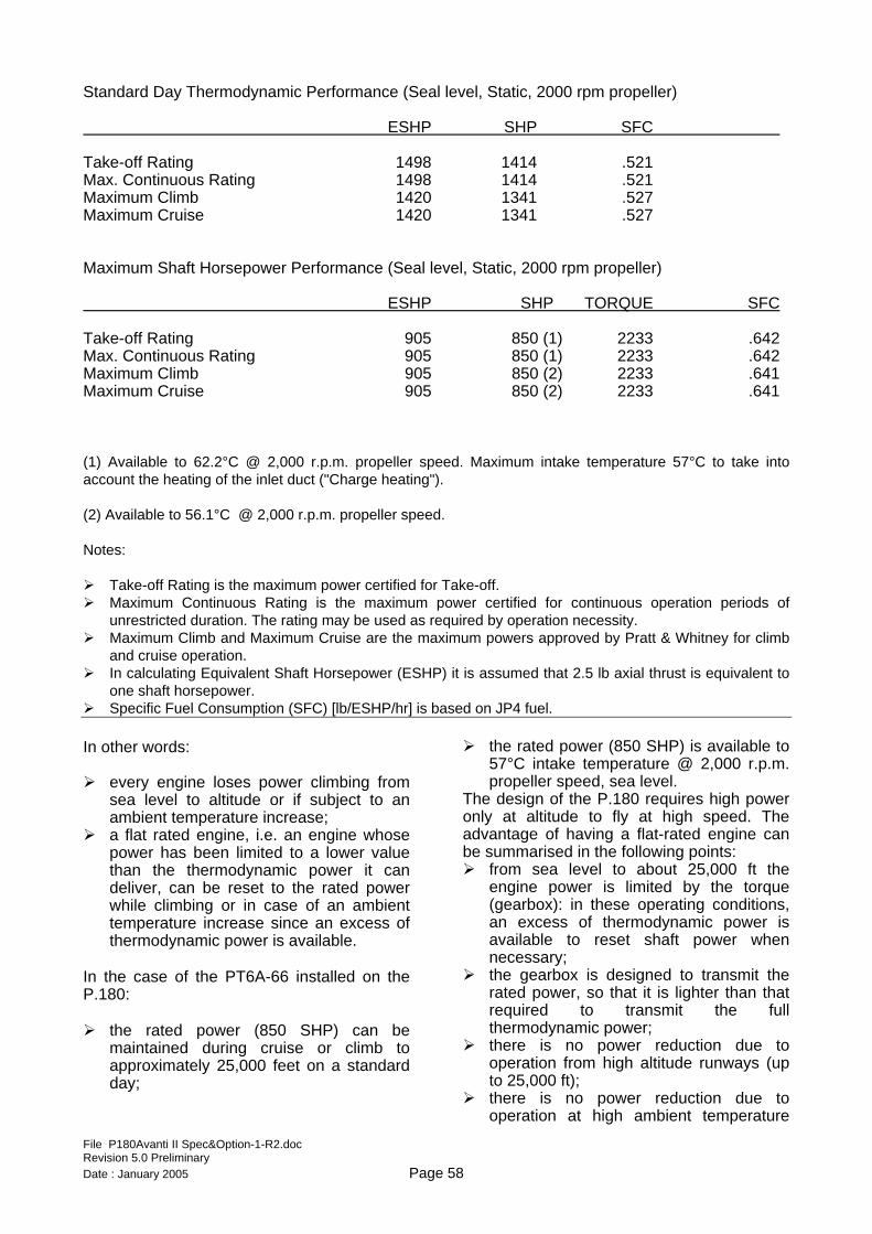
2.4 Powerplant Engines
Manufacturer PRATT & WHITNEY OF CANADA Model PT6A-66B Power Each 850 SHP 634 kW (flat rated from 1630 thermodynamic HP) Power Loading 6.79 lb/SHP 3.08 kg/SHP TBO 3600 hours
Propellers
Manufacturer HARTZELL Model HC-E5N Diameter 85 in 2159 mm Type Five-blade, constant speed, fully feathering, hydraulically controlled
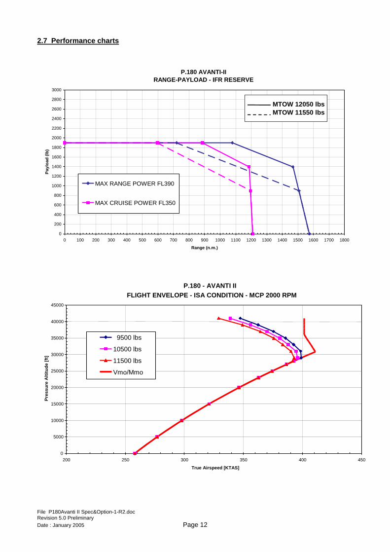
2.5 Performance
2.5.1 Take-off and Landing Take-off Distance (1)
@ Standard MTOW S.L., ISA 2850 ft 869 m @ Increased MTOW (see “List of Optional Equipment”) S.L., ISA 3350 ft 1021 m
Landing Distance (2)
@ Standard MLW S.L., ISA 2860 ft 872 m @ Increased MLW (see “List of Optional Equipment”) S.L., ISA 3065 ft 934 m
Rate of Climb
@ Standard MTOW S.L., ISA Both Engines 2950 ft/min 899 m/min One Engine 756 ft/min 230 m/min @ Increased MTOW (see “List of Optional Equipment”) S.L., ISA Both Engines 2770 ft/min 844 m/min One Engine 670 ft/min 204 m/min
Service Ceiling
Both Engines 40000 ft 12190 m One Engine (**) 25000 ft 7620 m
File P180Avanti II Spec&Option-1-R2.doc Revision 5.0 Preliminary
(**) Take-off at MTOW.
Date : January 2005 Page 9
Noise
The aircraft is compliant with certification noise levels specified in FAR 36, Appendix G, amdt. 16 and in ICAO Annex 16 Chapter 10.
2.5.2 Cruise Performance Maximum Speed (3) 398 KTAS 737 km/h Cruise Speed at Maximum Cruise Power (4)
At 30000 ft 395 KTAS 732 km/h At 35000 ft 380 KTAS 704 km/h At 39000 ft 356 KTAS 660 km/h
VFR Maximum Cruise Range at Maximum Range Power
At 39000 ft 1793 nm 3321 km
IFR Maximum Cruise Range at Maximum Range Power
At 39000 ft 1509 nm 2795 km
IFR Maximum Cruise Range at Maximum Cruise Power
At 39000 ft 1456 nm 2697 km
(1) FAR 23 runway requirement (2-engine Take-off to clear 50 feet) for turboprop aircraft. (2) Total distance over 50 feet, full flaps, without propeller reversing. Does not include
any runway factors for destination or alternate airports. (3) At 28000 feet and ISA Conditions. (4) Typical mid-cruise weights (operating weight + 7 PAX + 1/2 full fuel) ISA conditions and IFR reserves. Improvement over P180 Avanti is significant for payloads of 1000 lb or more
File P180Avanti II Spec&Option-1-R2.doc Revision 5.0 Preliminary Date : January 2005 Page 10
2.6 Operating Speeds
Stall Speed, Landing Configuration @ Standard MLW VSO 93 KIAS 172 km/h @ Increased MLW (see “List of Optional Equipment”) VSO 97 KIAS 179 km/h Maximum Operating Speed Limits VMO 260 KIAS 482 km/h MMO 0.7 Mach Maximum Flap Operating Speeds VFO flaps MID 170 KIAS 315 km/h VFO flaps DN 150 KIAS 278 km/h Maximum Flap Extended Speeds VFE flaps MID 180 KIAS 333 km/h VFE flaps DN 175 KIAS 324 km/h Maximum Landing Gear Operating Speed VLO 180 KIAS 333 km/h Maximum Landing Gear Extended Speed VLE 185 KIAS 343 km/h Minimum Control Airspeed VMCA 100 KIAS 185 km/h Manoeuvring Speed @ Standard MTOW VA 199 KIAS 368 km/h @ Increased MTOW (see “List of Optional Equipment”) VA 204 KIAS 378 km/h
File P180Avanti II Spec&Option-1-R2.doc Revision 5.0 Preliminary Date : January 2005 Page 11
File P180Avanti II Spec&Option-1-R2.doc Revision 5.0 Preliminary Date : January 2005 Page 12
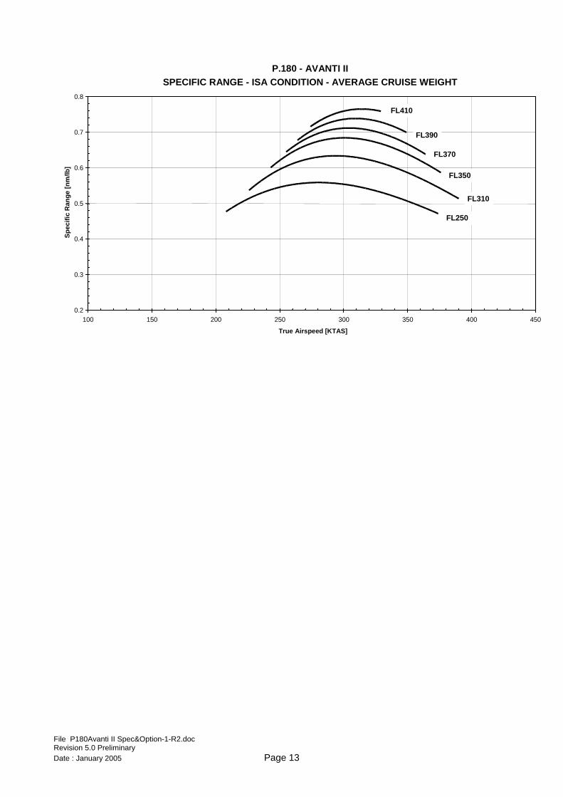
P.180 - AVANTI IISPECIFIC RANGE - ISA CONDITION - AVERAGE CRUISE WEIGHT
0.2
0.3
0.4
0.5
0.6
0.7
0.8
100 150 200 250 300 350 400 450
True Airspeed [KTAS]
Spec
ific
Ran
ge [n
m/lb
]
FL250
FL310
FL350
FL370
FL390
FL410
File P180Avanti II Spec&Option-1-R2.doc Revision 5.0 Preliminary Date : January 2005 Page 13
3. AIRFRAME
3.1 Fuselage group
The Avanti's fuselage has a circular cross section and is tapered at both ends. Cabin width extends up to 6 feet (1828 mm) and a dropped aisle provides a cabin height of 5 feet 9 inches (1753 mm). The two-part cabin door is located on the left-hand side of the fuselage and is 53 inches (1346 mm) high and 24 inches (610 mm) wide. The upper half of the door is side-hinged and swings forward to open. The lower cabin door is bottom-hinged and opens downward to serve as an air stair. A plug-type emergency exit hatch is located on the right-hand side of the cabin, opposite to the cabin door. The aft fuselage extends from the aft pressure bulkhead to the tail-cone and is divided into two sections: the wing/fuselage intersection area and the baggage compartment area. Within the wing/fuselage intersection area, the space over the wing and between the forward and central bulkheads contains an integral fuel tank which is divided into two parts by a central panel and interconnected with the wing tanks. Most of the accessories are located in the aft fuselage underneath the wing. The baggage compartment is located in the aft part of the fuselage between the third wing spar bulkhead and the tail-cone. Baggage compartment length is 76.8 (1951 mm) inches and the total volume measures 44 cubic feet (1.25 m3). The baggage door is a composite part and is hinged on the top. The tail-cone is attached to the rear fuselage and supports the empennage.
3.2 Wing group
The Avanti has a three-lifting-surface design using a forward wing, an aft fuselage-mounted main wing, and a horizontal stabiliser on top of the vertical fin. The wing has an aspect ratio of 11.96, a taper ratio of .34, a dihedral of 2° and a sweep of 1°11' (lading edge). The airfoil thickness varies from 13% at the tip to 14.5% at the nacelle. Inboard of the nacelle the wing has an average thickness of 13.5%.
File P180Avanti II Spec&Option-1-R2.doc Revision 5.0 Preliminary Date : January 2005 Page 14
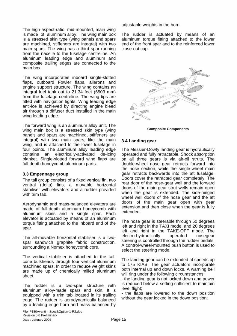
The high-aspect-ratio, mid-mounted, main wing is made of aluminum alloy. The wing main box is a stressed skin type (wing panels and spars are machined, stiffeners are integral) with two main spars. The wing has a third spar running from the nacelle to the fuselage centreline. An aluminum leading edge and aluminum and composite trailing edges are connected to the main box. The wing incorporates inboard single-slotted flaps, outboard Fowler flaps, ailerons and engine support structure. The wing contains an integral fuel tank out to 21.34 feet (6503 mm) from the fuselage centreline. The wing tips are fitted with navigation lights. Wing leading edge anti-ice is achieved by directing engine bleed air through a diffuser duct installed in the main wing leading edge. The forward wing is an aluminum alloy unit. The wing main box is a stressed skin type (wing panels and spars are machined, stiffeners are integral) with two main spars, like the main wing, and is attached to the lower fuselage in four points. The aluminum alloy leading edge contains an electrically-activated de-icing blanket. Single-slotted forward wing flaps are full-depth honeycomb aluminum parts.
3.3 Empennage group The tail group consists of a fixed vertical fin, two ventral (delta) fins, a movable horizontal stabiliser with elevators and a rudder provided with trim tab. Aerodynamic and mass-balanced elevators are made of full-depth aluminum honeycomb with aluminum skins and a single spar. Each elevator is actuated by means of an aluminum torque fitting attached to the inboard end of the spar. The all-movable horizontal stabiliser is a two- spar sandwich graphite fabric construction, surrounding a Nomex honeycomb core. The vertical stabiliser is attached to the tail-cone bulkheads through four vertical aluminum machined spars. In order to reduce weight skins are made up of chemically milled aluminum sheet. The rudder is a two-spar structure with aluminum alloy-made spars and skin. It is equipped with a trim tab located in its trailing edge. The rudder is aerodynamically balanced by a leading edge horn and mass balanced by
adjustable weights in the horn. The rudder is actuated by means of an aluminum torque fitting attached to the lower end of the front spar and to the reinforced lower close-out cap.
Composite Components
3.4 Landing gear
The Messier-Dowty landing gear is hydraulically operated and fully retractable. Shock absorption on all three gears is via air-oil struts. The double-wheel nose gear retracts forward into the nose section, while the single-wheel main gear retracts backwards into the aft fuselage. Doors cover the retracted gear completely. The rear door of the nose-gear well and the forward doors of the main-gear strut wells remain open when the gear is extended. The side-hinged wheel well doors of the nose gear and the aft doors of the main gear open with gear extension and then close when the gear is fully extended. The nose gear is steerable through 50 degrees left and right in the TAXI mode, and 20 degrees left and right in the TAKE-OFF mode. The electro-hydraulically operated nosegear steering is controlled through the rudder pedals. A control-wheel-mounted push button is used to select the steering mode. The landing gear can be extended at speeds up to 175 KIAS. The gear actuators incorporate both internal up and down locks. A warning bell will ring under the following circumstances: - the landing gear is not locked down and power is reduced below a setting sufficient to maintain level flight; - the flaps are lowered to the down position without the gear locked in the down position;
File P180Avanti II Spec&Option-1-R2.doc Revision 5.0 Preliminary Date : January 2005 Page 15
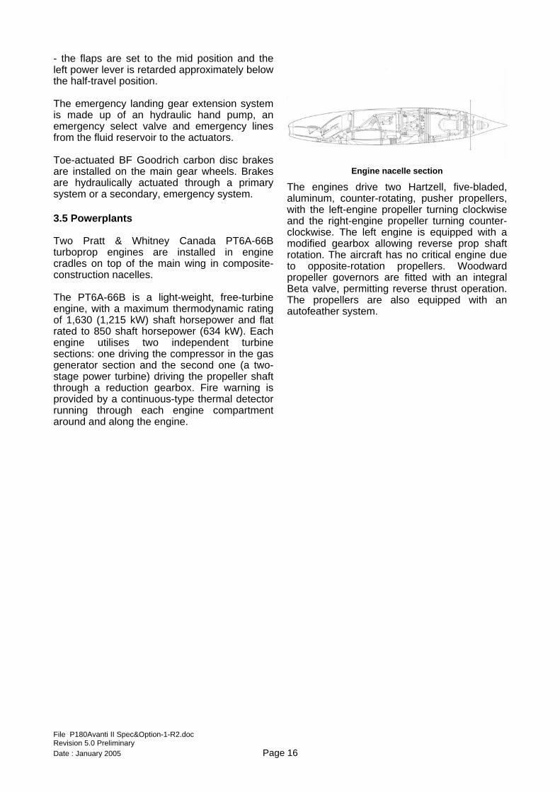
- the flaps are set to the mid position and the left power lever is retarded approximately below the half-travel position. The emergency landing gear extension system is made up of an hydraulic hand pump, an emergency select valve and emergency lines from the fluid reservoir to the actuators. Toe-actuated BF Goodrich carbon disc brakes are installed on the main gear wheels. Brakes are hydraulically actuated through a primary system or a secondary, emergency system. 3.5 Powerplants Two Pratt & Whitney Canada PT6A-66B turboprop engines are installed in engine cradles on top of the main wing in composite-construction nacelles. The PT6A-66B is a light-weight, free-turbine engine, with a maximum thermodynamic rating of 1,630 (1,215 kW) shaft horsepower and flat rated to 850 shaft horsepower (634 kW). Each engine utilises two independent turbine sections: one driving the compressor in the gas generator section and the second one (a two-stage power turbine) driving the propeller shaft through a reduction gearbox. Fire warning is provided by a continuous-type thermal detector running through each engine compartment around and along the engine.
Engine nacelle section
The engines drive two Hartzell, five-bladed, aluminum, counter-rotating, pusher propellers, with the left-engine propeller turning clockwise and the right-engine propeller turning counter-clockwise. The left engine is equipped with a modified gearbox allowing reverse prop shaft rotation. The aircraft has no critical engine due to opposite-rotation propellers. Woodward propeller governors are fitted with an integral Beta valve, permitting reverse thrust operation. The propellers are also equipped with an autofeather system.
File P180Avanti II Spec&Option-1-R2.doc Revision 5.0 Preliminary Date : January 2005 Page 16
4. SYSTEMS
4.1 Flight Controls Control surfaces are mechanically connected to the pilot controls via cables, pulleys, push-pull rods and bellcranks in a closed loop system. Primary controls are made up of ailerons, elevators and rudder. The pilot controls are made up of a control wheel hinged on a yoke control column and adjustable rudder pedals hinged on the cockpit floor, in a dual-pilot control configuration.
File P180Avanti II Spec&Option-1-R2.doc Revision 5.0 Preliminary
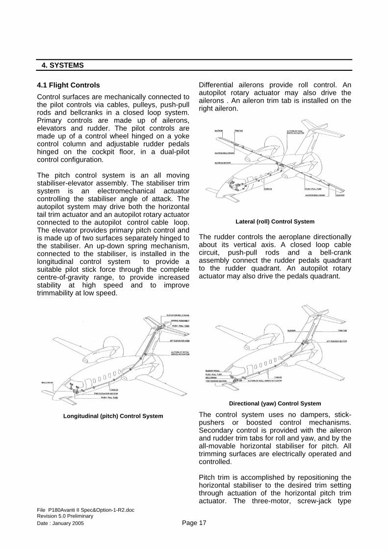
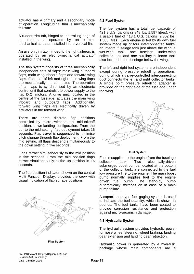
The pitch control system is an all moving stabiliser-elevator assembly. The stabiliser trim system is an electromechanical actuator controlling the stabiliser angle of attack. The autopilot system may drive both the horizontal tail trim actuator and an autopilot rotary actuator connected to the autopilot control cable loop. The elevator provides primary pitch control and is made up of two surfaces separately hinged to the stabiliser. An up-down spring mechanism, connected to the stabiliser, is installed in the longitudinal control system to provide a suitable pilot stick force through the complete centre-of-gravity range, to provide increased stability at high speed and to improve trimmability at low speed.
Longitudinal (pitch) Control System
Differential ailerons provide roll control. An autopilot rotary actuator may also drive the ailerons . An aileron trim tab is installed on the right aileron.
Lateral (roll) Control System
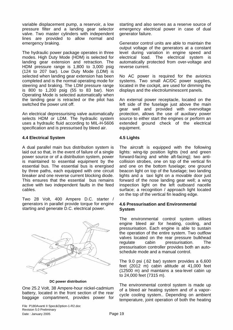
The rudder controls the aeroplane directionally about its vertical axis. A closed loop cable circuit, push-pull rods and a bell-crank assembly connect the rudder pedals quadrant to the rudder quadrant. An autopilot rotary actuator may also drive the pedals quadrant.
Directional (yaw) Control System
The control system uses no dampers, stick-pushers or boosted control mechanisms. Secondary control is provided with the aileron and rudder trim tabs for roll and yaw, and by the all-movable horizontal stabiliser for pitch. All trimming surfaces are electrically operated and controlled. Pitch trim is accomplished by repositioning the horizontal stabiliser to the desired trim setting through actuation of the horizontal pitch trim actuator. The three-motor, screw-jack type
Date : January 2005 Page 17
actuator has a primary and a secondary mode of operation. Longitudinal trim is mechanically fail-safe. A rudder trim tab, hinged to the trailing edge of the rudder, is operated by an electro-mechanical actuator installed in the vertical fin. An aileron trim tab, hinged to the right aileron, is operated by an electro-mechanical actuator installed in the wing. The flap system consists of three mechanically independent sets of flaps: main wing outboard flaps, main wing inboard flaps and forward wing flaps. Each set of left and right main wing flaps are mechanically interconnected. The operation of all flaps is synchronised by an electronic control unit that controls the power supply to the flap D.C. motors. A drive unit, located in the centre of the fuselage, actuates the main wing inboard and outboard flaps. Additionally, forward wing flaps are electrically driven by actuators in the forward wing. There are three discrete flap positions controlled by micro-switches: up, mid-takeoff position, down-landing configuration. From the up- to the mid-setting, flap deployment takes 16 seconds. Flap travel is sequenced to minimise pitch change through flap deployment. From the mid setting, all flaps descend simultaneously to the down setting in five seconds. Flaps retract simultaneously to the mid position in five seconds. From the mid position flaps retract simultaneously to the up position in 16 seconds. The flap position indicator, shown on the central Multi Function Display, provides the crew with visual indication of flap surface positions.
Flap System
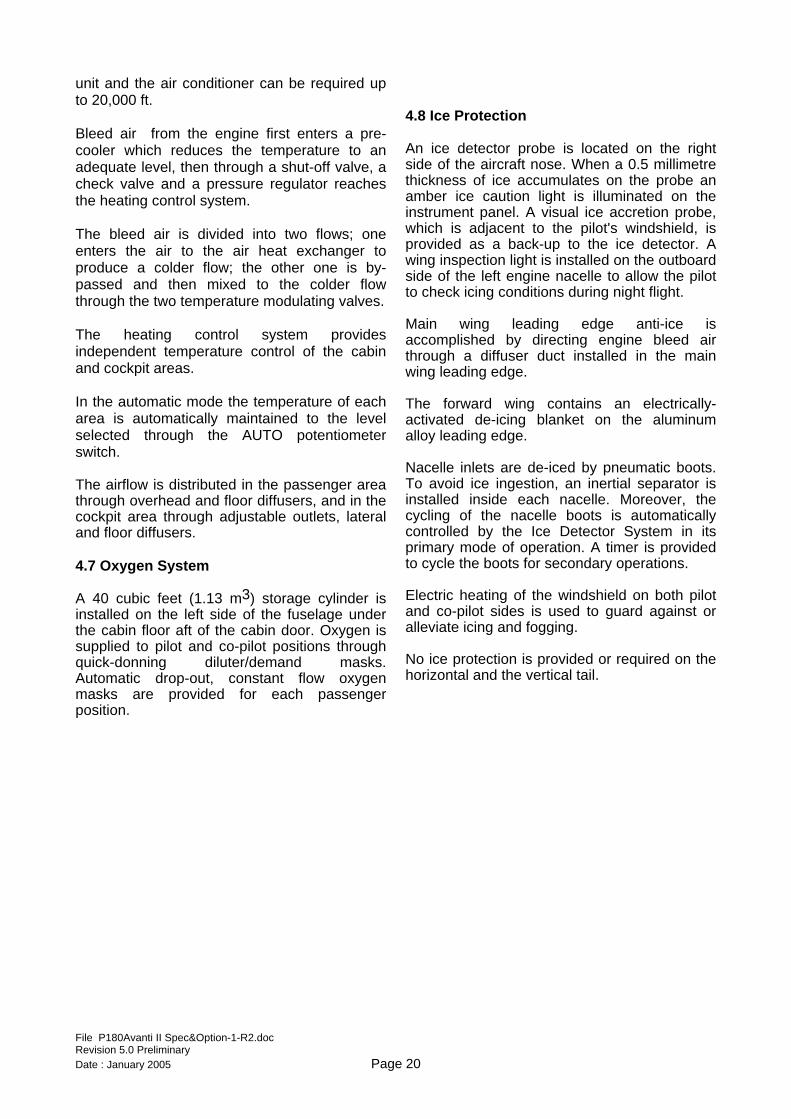
4.2 Fuel System The fuel system has a total fuel capacity of 421.9 U.S. gallons (2,848 lbs, 1,597 litres), with a usable fuel of 418.1 U.S. gallons (2,802 lbs, 1,583 litres). Each engine is fed by its own fuel system made up of four interconnected tanks: an integral fuselage tank just above the wing, a wet-wing tank, one fuselage under-wing collector tank and one auxiliary collector tank also located in the fuselage below the wing. The left and right fuel systems are independent except during pressure refuelling operations, during which a valve-controlled interconnecting duct connects the left and right collector tanks. A single point pressure refuelling adapter is provided on the right side of the fuselage under the wing.
Fuel System
Fuel is supplied to the engine from the fuselage collector tank. Two electrically-driven submerged boost pumps, located at the bottom of the collector tank, are connected to the fuel low pressure line to the engine. The main boost pump normally supplies fuel to the engine driven fuel pump. The stand-by pump automatically switches on in case of a main pump failure. A capacitance-type fuel gaging system is used to indicate the fuel quantity, which is shown in pounds. The fuel tanks have been coated to provide corrosion resistance and protection against micro-organism damage.
4.3 Hydraulic System The hydraulic system provides hydraulic power for nose wheel steering, wheel braking, landing gear extension and landing gear retraction. Hydraulic power is generated by a hydraulic package whose main components are a
File P180Avanti II Spec&Option-1-R2.doc Revision 5.0 Preliminary Date : January 2005 Page 18
variable displacement pump, a reservoir, a low pressure filter and a landing gear selector valve. Two master cylinders with independent lines are provided to allow normal and emergency braking. The hydraulic power package operates in three modes. High Duty Mode (HDM) is selected for landing gear extension and retraction. The HDM pressure range is 1,800 to 3,000 psig (124 to 207 bar). Low Duty Mode (LDM) is selected when landing gear extension has been completed and is the normal operating mode for steering and braking. The LDM pressure range is 800 to 1,200 psig (55 to 83 bar). Non Operating Mode is selected automatically when the landing gear is retracted or the pilot has switched the power unit off. An electrical depressurising valve automatically selects HDM or LDM. The hydraulic system uses a hydraulic fluid according to MIL-H-5606 specification and is pressurised by bleed air.
4.4 Electrical System A dual parallel main bus distribution system is laid out so that, in the event of failure of a single power source or of a distribution system, power is maintained to essential equipment by the essential bus. The essential bus is energised by three paths, each equipped with one circuit breaker and one reverse current blocking diode. This ensures that the essential bus remains active with two independent faults in the feed cables. Two 28 Volt, 400 Ampere D.C. starter / generators in parallel provide torque for engine starting and generate D.C. electrical power.
DC power distribution
One 25.2 Volt, 38 Ampere-hour nickel-cadmium battery, located in the front section of the rear baggage compartment, provides power for
starting and also serves as a reserve source of emergency electrical power in case of dual generator failure. Generator control units are able to maintain the output voltage of the generators at a constant level during variation in engine speed and electrical load. The electrical system is automatically protected from over-voltage and reverse current. No AC power is required for the avionics systems. Two small AC/DC power supplies, located in the cockpit, are used for dimming the displays and the electroluminescent panels. An external power receptacle, located on the left side of the fuselage just above the main gear well and provided with overvoltage protection, allows the use of auxiliary power source to either start the engines or perform an extended ground check of the electrical equipment.
4.5 Lights The aircraft is equipped with the following lights: wing-tip position lights (red and green forward-facing and white aft-facing); two anti-collision strobes, one on top of the vertical fin and one on the bottom fuselage; one ground beacon light on top of the fuselage; two landing lights and a taxi light on a movable door just forward of the nose landing gear well; a wing inspection light on the left outboard nacelle surface; a recognition / approach light located on the top of the vertical fin leading edge.
4.6 Pressurisation and Environmental System The environmental control system utilises engine bleed air for heating, cooling, and pressurisation. Each engine is able to sustain the operation of the entire system. Two outflow valves located on the rear pressure bulkhead regulate cabin pressurisation. The pressurisation controller provides both an auto-schedule mode and a manual control. The 9.0 psi (.62 bar) system provides a 6,600 feet (2012 m) cabin altitude at 41,000 feet (12500 m) and maintains a sea-level cabin up to 24,000 feet (7315 m). The environmental control system is made up of a bleed air heating system and of a vapor-cycle cooling system.. Depending on ambient temperature, joint operation of both the heating
File P180Avanti II Spec&Option-1-R2.doc Revision 5.0 Preliminary Date : January 2005 Page 19
unit and the air conditioner can be required up to 20,000 ft. Bleed air from the engine first enters a pre-cooler which reduces the temperature to an adequate level, then through a shut-off valve, a check valve and a pressure regulator reaches the heating control system. The bleed air is divided into two flows; one enters the air to the air heat exchanger to produce a colder flow; the other one is by-passed and then mixed to the colder flow through the two temperature modulating valves. The heating control system provides independent temperature control of the cabin and cockpit areas. In the automatic mode the temperature of each area is automatically maintained to the level selected through the AUTO potentiometer switch. The airflow is distributed in the passenger area through overhead and floor diffusers, and in the cockpit area through adjustable outlets, lateral and floor diffusers.
4.7 Oxygen System A 40 cubic feet (1.13 m3) storage cylinder is installed on the left side of the fuselage under the cabin floor aft of the cabin door. Oxygen is supplied to pilot and co-pilot positions through quick-donning diluter/demand masks. Automatic drop-out, constant flow oxygen masks are provided for each passenger position.
4.8 Ice Protection An ice detector probe is located on the right side of the aircraft nose. When a 0.5 millimetre thickness of ice accumulates on the probe an amber ice caution light is illuminated on the instrument panel. A visual ice accretion probe, which is adjacent to the pilot's windshield, is provided as a back-up to the ice detector. A wing inspection light is installed on the outboard side of the left engine nacelle to allow the pilot to check icing conditions during night flight. Main wing leading edge anti-ice is accomplished by directing engine bleed air through a diffuser duct installed in the main wing leading edge. The forward wing contains an electrically-activated de-icing blanket on the aluminum alloy leading edge. Nacelle inlets are de-iced by pneumatic boots. To avoid ice ingestion, an inertial separator is installed inside each nacelle. Moreover, the cycling of the nacelle boots is automatically controlled by the Ice Detector System in its primary mode of operation. A timer is provided to cycle the boots for secondary operations. Electric heating of the windshield on both pilot and co-pilot sides is used to guard against or alleviate icing and fogging. No ice protection is provided or required on the horizontal and the vertical tail.
File P180Avanti II Spec&Option-1-R2.doc Revision 5.0 Preliminary Date : January 2005 Page 20
5. INSTRUMENTATION AND AVIONICS
5.1 General Cockpit layout includes two complete crew stations equipped with dual controls, including control columns, adjustable rudder pedals and brakes. Crew seats are fully adjustable and include four-point restraint harness. An emergency oxygen system provides two diluter/demand masks for the crew members. Cockpit lighting includes dome lights, instrument panel flood lights, internally-lighted instruments and dual map lights. Two heated Pitot tubes and two heated static ports (each one with two independent sources) provide Pitot/static pressure to flight instruments. Independent sources are used to drive the pilot's and co-pilot's flight instruments. 5.2 Electronic Flight Displays The Collins ProLine 21 Electronic Flight Instrument System (EFIS) is an integrated system able to gather, concentrate, and display aircraft information to the flight crew. The EFIS includes the following units: Three 8″x10″ color Liquid Crystal
Adaptive Flight Displays (AFD) Two Display Control Panels (DCP) One Cursor Control Panel (CCP) An Integrated Avionics Processor System
(IAPS) Four Data Concentrator Units (DCU)
Three identical AFDs are arranged on the instrument panel as shown in Figures on pages 23 and 24. Under normal conditions the two lateral displays are configured as Primary Flight Displays (PFD) and the central display is configured as a Multi-Function Display (MFD) shared by the pilots. Each PFD provides attitude, heading, airspeed, altitude, vertical speed, Flight Control System (FCS) annunciation, and navigation data on a single, integrated display.
File P180Avanti II Spec&Option-1-R2.doc Revision 5.0 Preliminary
The PFDs also provide Engine Indication System (EIS) displaying information if selected in reversionary mode. EIS display information is always displayed on the MFD.
The PFDs display a full Compass Rose, a partial Compass Arc, or a flat Compass Tape immediately beneath the attitude ball. Current heading is read opposite the lubber line. This display incorporates a pilot controllable Selected Heading Bug. The heading bug is controlled by the HDG rotary knob on the Flight Guidance Panel (FGP). The PFDs provide also a Track Pointer, wind data, lateral navigation course and deviation data, distance data, Marker Beacon information, ILS information, vertical deviation data, VNAV deviation data, radio altitude, Decision Height and Minimum Descent Altitude, map display and a Flight Management System (FMS) Message Window. 5.3 Multi-Function Display (MFD) The MFD is consists of three major display areas: the Engine Indication System (EIS) region and the upper and lower Multi-Function Windows (MFW) below it. The EIS region is displayed across the upper portion of the MFD. The area below the engine instruments is divided into upper and lower format windows. The contents of both format windows can be separately controlled by the pilot. The EIS area continuously shows engine parameters. The engine display format consists of a full time window showing ITT and Torque on a shared analog gauge and NG and Prop RPM on individual smaller analog gauges. Digital displays for Fuel Flow, Oil Pressure, Oil Temperature, and Fuel Quantity are also part of the EIS window. There are two independent sources for the primary engine parameters (ITT, Torque, NG and Prop RPM) for each engine: one is the Data Concentrator Unit (DCU) and the other is the Engine Data Concentrator (EDC). The DCU is normally the source of all displayed engine data and the EDC is a secondary source of all displayed engine data. The Upper MFW can display either a Checklist or an FMS Text Window. The Lower MFW can show either a compass rose, a compass arc, a present position map
Date : January 2005 Page 21
(PPOS), a plan map, TCAS information, a systems page, or graphical weather data (optional) The two windows can be merged into a Full Format window showing either FMS remote text, database effectiveness, electronic charts (optional), maintenance main menu, FCS diagnostics, File Server configuration (optional) The ProLine 21 system may include an optional File Server Unit (FSU) providing electronic charts, uplinked graphical weather, and enhanced map features to traditional map displays (e.g., rivers, lakes, and national boundaries). The FSU can be connected to an optional Ethernet-capable MFD providing a control interface to these enhanced features using a Cursor Control Panel (CCP). Further information is provided in the Options section of this document. 5.4 Radio Sensor System The Radio Sensor System (RSS) is made up of a single CDU-3000 display unit and a single RTU-4200 tuning unit providing a primary LCD-based integrated display system for communication and navigation operations within the Air Traffic Control environment. The basic communication system includes two VHF-4000 Communication Transceivers (a third transceiver for data link is optional), one TDR-94D ATC Mode-S Transponder (a second transponder is optional), one DME-4000 transceiver (a second receiver is optional), one NAV-4000 VOR/ILS/MKR/ADF receivers and one NAV-4500 VOR/ILS/MKR Receiver (a second ADF receiver is optional). 5.5 Flight Management System The FMS-3000 satellite-based navigation system provides the capability to perform en route, terminal, and nonprecision approach lateral navigation. The system contains an advanced GPS receiver and processes the transmissions from multiple GPS satellites simultaneously to calculate navigation solutions based on information from all satellites in view. Attitude Heading System (AHS), Air Data Computer (ADC), DME and VOR data are also used by the FMS. The FMS provides necessary controls for all input sensors, if appropriate.
File P180Avanti II Spec&Option-1-R2.doc Revision 5.0 Preliminary
A Coupled VNAV interface with the FCS allows the FMS VNAV function to select various FCS vertical modes of navigation. The FMS interfaces with the Data Base Unit (DBU) to update its internal Data Base and with the EFIS Displays to provide conventional navigation information and state-of-the-art map presentation. 5.6 Weather Radar System The Collins RTA-852 Turbulence Detection Radar is a stabilized, solid state, X-band color radar system. The weather and map information can be overlaid on either or both PFDs and MFDs on most of the navigation display formats. The Control Panels provide the radar mode menu selection, range select knob, tilt knob and ground clutter suppression knob. With two PFDs operational, each display is controlled separately by its own Display Control Panel (DCP)/PFD and is updated on alternate sweeps of the antenna. 5.7 Flight Control System The Flight Control System (FCS) is made up of a dual Flight Guidance System and of a 3 axis Autopilot, including Yaw Damper and Pitch Trim control. The pilot selects the Flight Guidance Computer (FGC) in control with the Flight Guidance Panel’s (FGP) CPL switch. Each PFD displays the Flight Director (FD) commands from the Flight Guidance Computer selected with the CPL switch, except for Go Around (GA) and Approach (APPR) modes. The GA and APPR modes are Independent Modes, and only the on-side Flight Guidance Computer guidance is used by the associated PFD for Independent Modes. 5.8 Checklist System The MDC-3110 Maintenance Diagnostic System gives the possibility to show aircraft checklists on the MFD. There is a preamble
Date : January 2005 Page 22
page, which requires pilot acknowledgement, and up to four checklist types available: 1) Normal Checklist 2) Abnormal Checklist 3) Emergency Checklist 4) User Checklist The checklists are generated off-line on a personal computer capable of running Windows 95™ (or newer), and capable of interfacing to a 3.5″ floppy disk drive. 5.9 TCAS System An L3 Communications Skywatch HP TCAS I airborne Traffic Alert and Collision Avoidance System is provided as standard equipment. The TCAS system interrogates ATC transponders in nearby aircraft and uses computer processing to identify and display potential and predicted collision threats. TCAS traffic information can be selected for pictorial display on the PFD and/or the MFD to indicate the presence of other aircraft within a selected range around the aircraft. 5.10 TAWS An L3 Communications Landmark Class-B TAWS Terrain Awareness and Warning System is provided as standard equipment. The system provides traditional Ground Proximity Warning System (GPWS) functionality to prevent Controlled Flight Into Terrain, enhanced by a stored worldwide database including terrain, airport and obstacle data.
TAWS provides the pilot with predictive warnings based on comparison between stored obstacle data and a prediction of the aircraft’s flight path derived from FMS and GPS data and current flight parameters. TAWS provides aural and visual warnings to alert the pilot in case a hazardous condition is detected and includes the possibility to represent terrain elevation features on the AFDs graphically. 5.11 Stand-by Instruments An L3 integrated stand-by instrument located on the top of the centre instrument panel and supplied by an emergency battery provides emergency flight information in case of total loss of all displays. 5.12 ELT A Techtest Model 503 3-frequency ELT transmits on the two International Emergency Frequencies of 121.5 and 243.0 MHz as well as on the satellite frequency of 406.025 MHz. The system is activated either automatically by a g-switch or by the crew through a switch located in the cockpit. 5.13 Additional features The standard ProLine 21 avionics system of the P180 provides the capability to operate in RVSM-airspace and to perform Category II approaches and steep approaches. The flight envelope extension to Mach 0,7 Mmo is also a standard feature.
File P180Avanti II Spec&Option-1-R2.doc Revision 5.0 Preliminary Date : January 2005 Page 23
6. INTERIOR
6.1 General The cabin is separated from the cockpit by dividers. The fuselage is shaped in such a way to minimise drag, providing at the same time the maximum possible interior room. Thus the Avanti fuselage has a tapering cabin cross-section, with maximum height and width achieved in the middle of the cabin. Cabin length is 14.5 feet (4.42 m). Width measures 72 inches (1.829 m) and height 69 inches (1.753 m) from the 6.5 inches (165 mm) dropped aisle to the cabin ceiling. The cabin interior may be designed for six to nine passengers. The aircraft has an externally accessible baggage compartment measuring 44 cubic feet (1.24 m3). The interior furnishing is manufactured of composite honeycomb shell to provide maximum strength, durability and an acoustically quiet environment . The interior has also been designed to allow individual owners to select the surface finish at their own desires. Passenger seats slide fore and aft eight inches, laterally outward from the sidewall four inches, swivel 180 degrees, and recline 55 degrees. The armrest contains individual fingertip controls for air conditioning, light and entertainment headset volume. All passenger seats are equipped with a shoulder harness for take-off and landing. Constant flow oxygen masks automatically deploy for each passenger in case a sudden change in cabin pressure is detected by the cabin pressurisation system.
6.2 Cabin Standard interior configurations include the following: Four seats in a club arrangement in the
rear cabin. Two side-facing divans or one side-facing
divan and a forward-facing seat or two forward-facing seats in the forward cabin. A toilet seat approved for take-off and
landing. One or more refreshment cabinets,
depending on the seat configuration,
containing storage areas for food and beverages, including areas for ice, soda cans and small bottles. There are two additional dispensers for heated beverages and storage space for glasses and cups and for miscellaneous items. Two folding desktops located between the
club seats. An armrest console running the length of
the main cabin and containing drink holders and storage for miscellaneous objects. Ashtrays are located in the seat armrest.
The aft lavatory is equipped with an electrically flushing toilet with an easy-to-maintain Teflon bowl. It has a fully secured, removable tank for servicing from the cabin. The lavatory is separated from the cabin by a sliding door to provide full privacy. The vanity facia contains a water tank with a drainable sink, a cosmetic mirror and towel, facial tissue, soap and toilet tissue dispensers. A stainless steel trash container is provided for solid or liquid waste. The rear closet is equipped with a door and provides a coat hanger for passenger coats as well as floor space for brief case storage. Passenger windows have opaque privacy shades and a reflective outer surface to reduce heat build-up on the ground. Five interior configurations are available, ranging from 7 or 6 seats VIP style, 7 seats airline style, Air Ambulance with one or two stretchers and several medical equipment (see “List of Optional Equipment”).
File P180Avanti II Spec&Option-1-R2.doc Revision 5.0 Preliminary Date : January 2005 Page 24
6.3 Cabin noise The internal cabin noise is significantly lower than in other turboprop aircraft and compares also favourably with noise of typical jet aircraft. Internal noise was measured on the ground and in flight using a Precision Sound Level Meter. Typical noise levels in various ground and flight conditions are reported in the table below:
6.4 Miscellaneous Cockpit Furnishings Two crew storage cabinets; Dual adjustable sun visors Dual cup holders; Two cockpit speakers; Cockpit dome lights; Instrument panel flood lights; Internally lighted instruments; Dual map lights; Portable fire extinguisher.
File P180Avanti II Spec&Option-1-R2.doc Revision 5.0 Preliminary Date : January 2005 Page 25
7. ACCESSORIES
7.1 Standard equipment
Cabin baggage straps Pitot covers TAT sensor cap Anti-ice detector cap Engine intake blanks Oil cooler inlet blanks Starter generator and inertial separator
blanks Air conditioning scoop cap Engine stack caps AOA transducer cap Static wick covers Baggage compartment net Telescoping tow bar Jack pads Lifting brackets
Mooring pads with rings Wheel chocks Gust locks Propeller restrainers Fuel drain tool Tool case
7.2 Emergency equipment
Portable fire extinguisher Crew and passenger oxygen Emergency exit lights Emergency lighting battery Emergency flashlight First Aid kit Cabin Fire Extinguisher
File P180Avanti II Spec&Option-1-R2.doc Revision 5.0 Preliminary Date : January 2005 Page 26
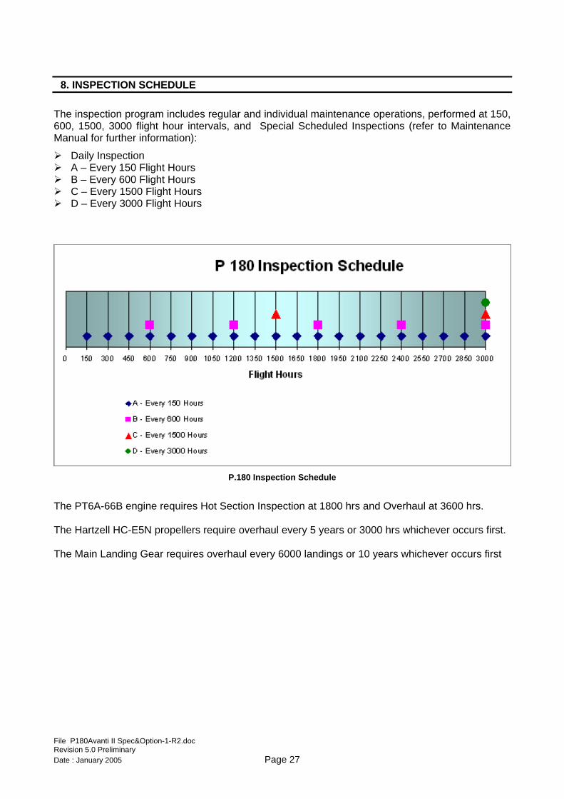
8. INSPECTION SCHEDULE The inspection program includes regular and individual maintenance operations, performed at 150, 600, 1500, 3000 flight hour intervals, and Special Scheduled Inspections (refer to Maintenance Manual for further information):
Daily Inspection A – Every 150 Flight Hours B – Every 600 Flight Hours C – Every 1500 Flight Hours D – Every 3000 Flight Hours
P.180 Inspection Schedule
The PT6A-66B engine requires Hot Section Inspection at 1800 hrs and Overhaul at 3600 hrs. The Hartzell HC-E5N propellers require overhaul every 5 years or 3000 hrs whichever occurs first. The Main Landing Gear requires overhaul every 6000 landings or 10 years whichever occurs first
File P180Avanti II Spec&Option-1-R2.doc Revision 5.0 Preliminary Date : January 2005 Page 27
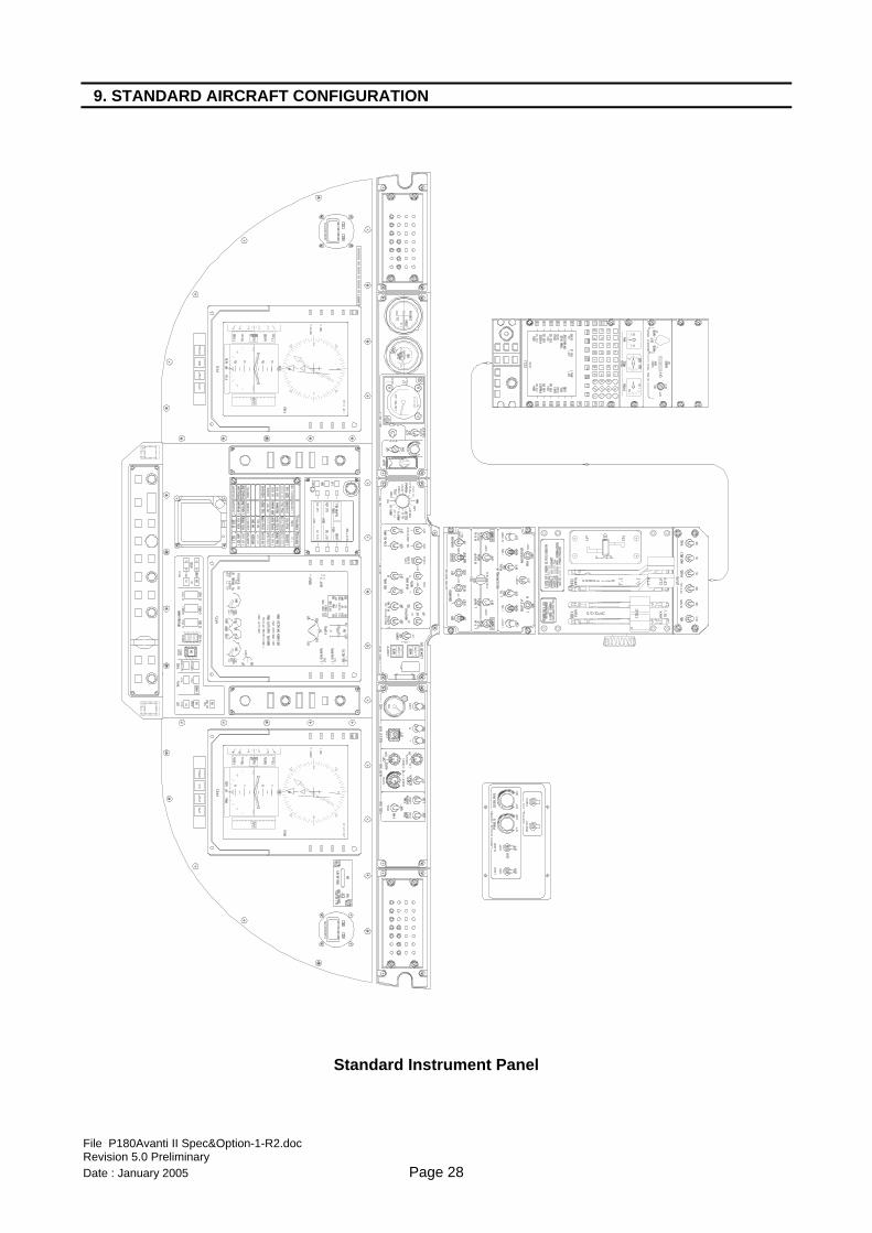
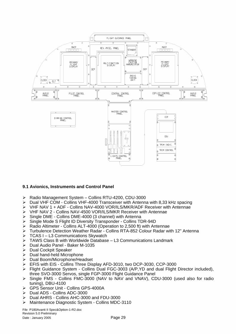
9. STANDARD AIRCRAFT CONFIGURATION
Standard Instrument Panel
File P180Avanti II Spec&Option-1-R2.doc Revision 5.0 Preliminary Date : January 2005 Page 28
9.1 Avionics, Instruments and Control Panel Radio Management System – Collins RTU-4200, CDU-3000 Dual VHF COM - Collins VHF-4000 Transceiver with Antenna with 8,33 kHz spacing VHF NAV 1 + ADF - Collins NAV-4000 VOR/ILS/MKR/ADF Receiver with Antennae VHF NAV 2 - Collins NAV-4500 VOR/ILS/MKR Receiver with Antennae Single DME - Collins DME-4000 (3 channel) with Antenna Single Mode S Flight ID Diversity Transponder - Collins TDR-94D Radio Altimeter - Collins ALT-4000 (Operation to 2,500 ft) with Antennae Turbulence Detection Weather Radar - Collins RTA-852 Colour Radar with 12" Antenna TCAS I – L3 Communications Skywatch TAWS Class B with Worldwide Database – L3 Communications Landmark Dual Audio Panel - Baker M-1035 Dual Cockpit Speaker Dual hand-held Microphone Dual Boom/Microphone/Headset EFIS with EIS - Collins Three Display AFD-3010, two DCP-3030, CCP-3000 Flight Guidance System - Collins Dual FGC-3003 (A/P,YD and dual Flight Director included),
three SVO-3000 Servos, single FGP-3000 Flight Guidance Panel Single FMS - Collins FMC-3000 (NAV to NAV and VNAV), CDU-3000 (used also for radio
tuning), DBU-4100 GPS Sensor Unit - Collins GPS-4000A Dual ADS - Collins ADC-3000 Dual AHRS - Collins AHC-3000 and FDU-3000 Maintenance Diagnostic System - Collins MDC-3110
File P180Avanti II Spec&Option-1-R2.doc Revision 5.0 Preliminary Date : January 2005 Page 29
Four Data Concentrator Unit - Collins DCU-3001 Stand-by Cluster Instrument – L3 Communications GH-3100 Emergency Locator Transmitter – Techtest Model 503 (3 frequency) Dual Clock (Flight Hour Meter included) Dual Master Annunciator Dual Turn&Slip Indicator Reversionary/Miscellaneous Panel for Avionics and Options management
NOTE: RVSM, Mach 0.7, Category II Landings and Steep Approach capabilities are included as standard.
9.2 Electrical Systems and Lights Two 400A, 28V Starter Generators Two Solid State Generator Control Unit Nickel-Cadmium Battery (38 Ah) External Power Receptacle with Overvoltage Protection Nine Busses DC Distribution System with Auto Load Sharing Dual Solid State Master Warning and Caution Panels with Self Test Solid State Warning and Caution Annunciator Panel with Self Test and Dimmer System Pitot Heating Monitor Static Wicks Heated Stall Warning System with Pre-flight Self Test System One Taxi and two Landing Lights Two Position Lights (each Wing Tip) Anti-Collision Strobe System (top and bottom) Recognition Light (On top of Vertical Fin) Ground Beacon Light with Flasher Unit Wing Ice Inspection Light Cockpit Dome Lights Flood Lights Instrument Lighting System Dual Map Lights in Cockpit Area Two 14VDC power outlets in passengers cabin Auxiliary Cabin Power Outlet.
9.3 Powerplant and related Systems
Two PRATT & WHITNEY model PT6A-66B Free Turbine Engines flat rated at 850 Shaft Horse
Power and Engine Accessories Two HARTZELL HC-E5N 85" diameter, five metal blades, fully feathering and reversible,
hydraulically controlled, constant speed propellers Magnetic Chip Detector Oil Quantity Dipstick Indicator Primary Propeller Governor Overspeed Propeller Governor N1 and N2 Magnetic Pick-up Speed Sensors Two Power Levers for Forward and Reverse Power Two Condition Levers for Propeller speed, High/Low Idle, Feather and Engine Cut-off Auto Ignition System Submerged electric main and standby Fuel Boost Pumps Fuel Control Unit Fuel Heater System Fuel Crossfeed System Low Fuel Quantity Warning System Two Fuel Quantity Indicators (on the Multi Function Display) Two Fuel Flow Indicators (on the Multi Function Display)
File P180Avanti II Spec&Option-1-R2.doc Revision 5.0 Preliminary Date : January 2005 Page 30
Fuel Drain System Fuel Tank Interconnect Pressure and Gravity Refuelling Low Oil Quantity Warning System Autofeather Complete Engine Anti-Icing System with Ice Protected Engine Inlet Engine Parameter Indication on Multi Function Display Engine Fire Detection System
9.4 Systems Oxygen System for Pilots (Two Diluter / Demand Masks) and Passengers (Ten Masks) Digital Cabin Pressure Control System with manual back-up - GARRETT Environmental Control System with Freon cooling system Forward Wing Anti-Ice System (Electrical) Main Wing Anti-Ice System (Hot air) Windshield Electrical Anti-Ice and Defogging Hydraulic Power Pack Dual heated Pitot and Static Ports with heating monitor Alternate Heated Static Source Propeller Synchrophaser Steerable Dual Wheel Nose Landing Gear - DOWTY Single Wheel Main Landing Gear - DOWTY Main Wheel and Tires (6.50 - 10) - GOODRICH Nose Wheels and Tires (5.00 - 5) - GOODRICH Carbon Brakes on each Main Wheel - GOODRICH Landing Gear Position Lights, Down and Locked Landing Gear Warning Horn and In-Transit Light Dual Conventional 3-Axis Aircraft Control System Dual Adjustable Rudder Pedals and Toe-Operated Brakes Parking Brake Emergency Landing Gear Extension System (Hand Pump) Electric Aileron Trim Tab (Roll) Electric Rudder Trim Tab (Yaw) Electric Stabiliser Trim Actuator (Pitch) Electric Flap System with Electronic Control Unit and Four Motors
File P180Avanti II Spec&Option-1-R2.doc Revision 5.0 Preliminary Date : January 2005 Page 31
10. DOCUMENTATION AND TECHNICAL PUBLICATIONS Deliverable Documents
1 Certificate of Conformity 2 Standard Airworthiness Certificate 3 Aircraft Log with Discrepancies Records 4 Pilot's Operating Handbook 5 Maintenance Manual 6 Illustrated Parts Catalogue 7 Wiring Manual 8 Engines Logs (RH and LH) 9 Engines Export Certificates 10 Propellers Logs (RH and LH) 11 Propellers Export Certificates 12 Hartzell Propellers Assembly Reports 13 PIAGGIO Propellers Assembly Reports 14 Serialised Components List 15 Warranty Certificate Application Forms for:
16 List of Service Bulletins and Service Letters 17 List of the warranties from Avionics manufacturers
Aircraft technical publications will be provided on CD-ROM.
File P180Avanti II Spec&Option-1-R2.doc Revision 5.0 Preliminary Date : January 2005 Page 32
List of Optional Equipment
Valid from SN 1105 onward
File P180Avanti II Spec&Option-1-R2.doc Revision 5.0 Preliminary Date : January 2005 Page 33
INTRODUCTION This section aims to provide a general description of all currently available options for the P180 Avanti II. All data contained in this document are subject to change without notice whenever this is necessary to comply with technical regulations or to improve the aircraft performance or characteristics. Equipment may be replaced with equivalent equipment providing the same or better functions at the manufacturer’s discretion. Options described in this section include: Passenger cabin configurations Avionics options Systems options
All options are certified and available within standard lead times, except where explicitly indicated. Other options may be designed and certified to suit Customer’s requests, however, lead times will be evaluated and defined case-by-case. The contents of this document will be continuously updated to include new options or to eliminate obsolete equipment. Options may be added or eliminated in order to comply with evolving regulations. Options consisting of “Provision for” are subject to the following Purchaser understanding: “Provisions” are designed to accommodate equipment or systems as presently available. Piaggio Aero Industries reserves the right to discontinue production of or to modify such equipment or system without notice. Such equipment or system may not be therefore available in the future and Piaggio Aero Industries has no obligation to substitute for, remove or complete the installation. Piaggio Aero Industries will guarantee the fully functional configuration if and only if the installation of the complete equipment or system is made by Piaggio Aero Industries or by an authorized Service Center.” Section 1 contains passenger cabin configurations. Sketches of interior elements are displayed for general information only. Actual design may differ slightly from the configuration shown. Piaggio Aero Industries reserves the right to change interior configurations and individual element design without notice. Sections 2 and 3 contain avionics and systems optional equipment respectively.
File P180Avanti II Spec&Option-1-R2.doc Revision 5.0 Preliminary Date : January 2005 Page 34
TABLE OF CONTENTS AND
PURCHASER OPTION SELECTION TABLE
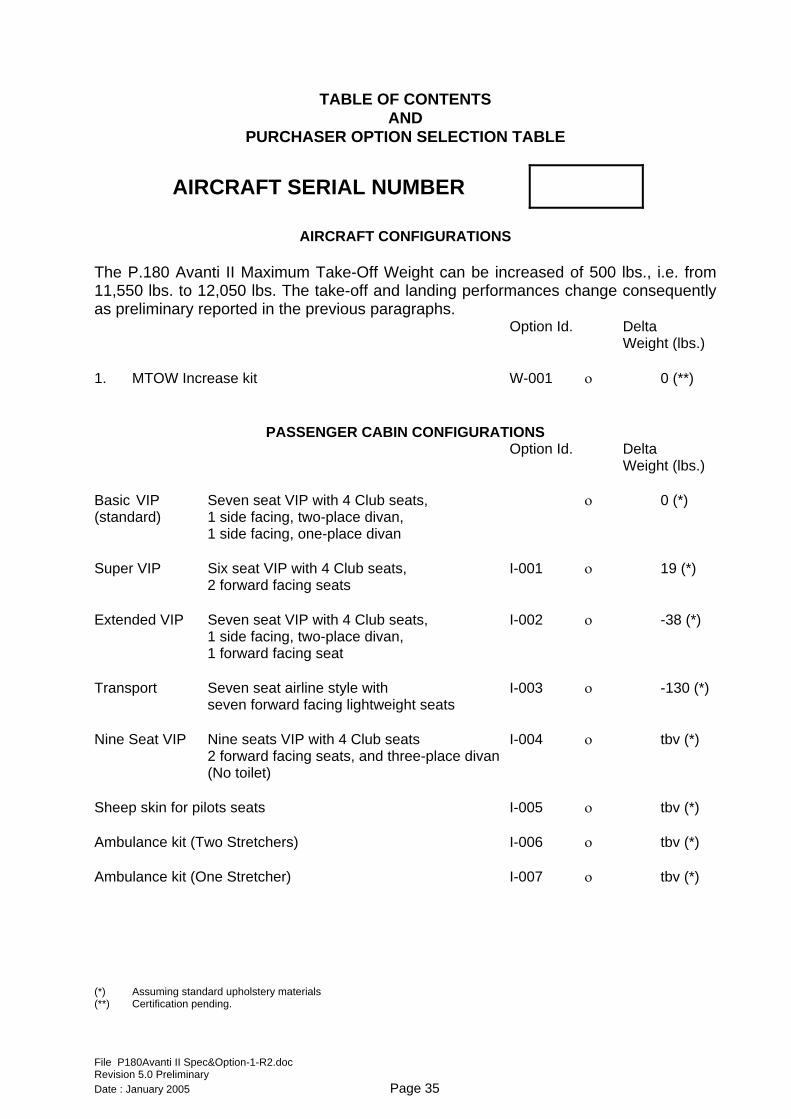
AIRCRAFT SERIAL NUMBER
AIRCRAFT CONFIGURATIONS
The P.180 Avanti II Maximum Take-Off Weight can be increased of 500 lbs., i.e. from 11,550 lbs. to 12,050 lbs. The take-off and landing performances change consequently as preliminary reported in the previous paragraphs. Option Id. Delta Weight (lbs.) 1. MTOW Increase kit W-001 ο 0 (**)
PASSENGER CABIN CONFIGURATIONS Option Id. Delta Weight (lbs.) Basic VIP Seven seat VIP with 4 Club seats, ο 0 (*) (standard) 1 side facing, two-place divan,
1 side facing, one-place divan Super VIP Six seat VIP with 4 Club seats, I-001 ο 19 (*)
2 forward facing seats Extended VIP Seven seat VIP with 4 Club seats, I-002 ο -38 (*)
1 side facing, two-place divan, 1 forward facing seat
Transport Seven seat airline style with I-003 ο -130 (*)
seven forward facing lightweight seats Nine Seat VIP Nine seats VIP with 4 Club seats I-004 ο tbv (*) 2 forward facing seats, and three-place divan (No toilet) Sheep skin for pilots seats I-005 ο tbv (*) Ambulance kit (Two Stretchers) I-006 ο tbv (*) Ambulance kit (One Stretcher) I-007 ο tbv (*) (*) Assuming standard upholstery materials (**) Certification pending.
File P180Avanti II Spec&Option-1-R2.doc Revision 5.0 Preliminary Date : January 2005 Page 35
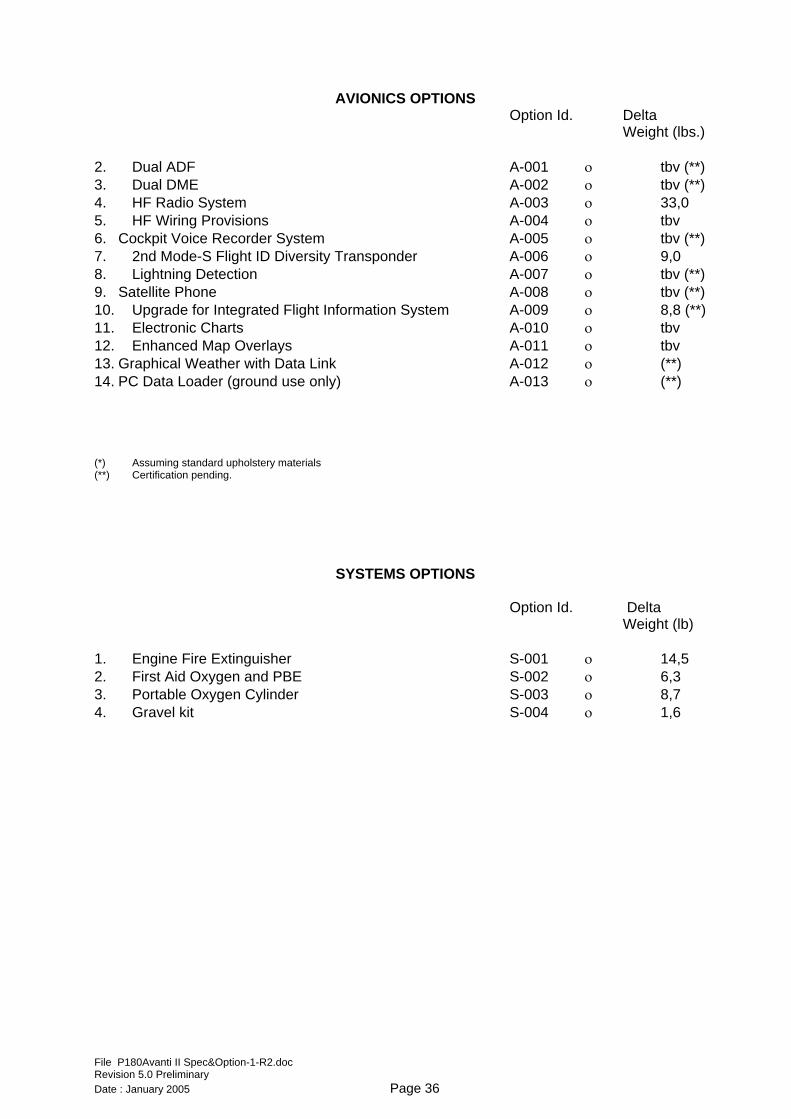
AVIONICS OPTIONS Option Id. Delta Weight (lbs.) 2. Dual ADF A-001 ο tbv (**) 3. Dual DME A-002 ο tbv (**) 4. HF Radio System A-003 ο 33,0 5. HF Wiring Provisions A-004 ο tbv 6. Cockpit Voice Recorder System A-005 ο tbv (**) 7. 2nd Mode-S Flight ID Diversity Transponder A-006 ο 9,0 8. Lightning Detection A-007 ο tbv (**) 9. Satellite Phone A-008 ο tbv (**) 10. Upgrade for Integrated Flight Information System A-009 ο 8,8 (**) 11. Electronic Charts A-010 ο tbv 12. Enhanced Map Overlays A-011 ο tbv 13. Graphical Weather with Data Link A-012 ο (**) 14. PC Data Loader (ground use only) A-013 ο (**) (*) Assuming standard upholstery materials (**) Certification pending.
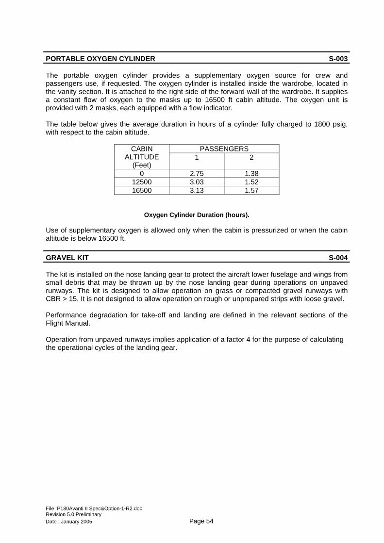
SYSTEMS OPTIONS Option Id. Delta Weight (lb) 1. Engine Fire Extinguisher S-001 ο 14,5 2. First Aid Oxygen and PBE S-002 ο 6,3 3. Portable Oxygen Cylinder S-003 ο 8,7 4. Gravel kit S-004 ο 1,6
File P180Avanti II Spec&Option-1-R2.doc Revision 5.0 Preliminary Date : January 2005 Page 36
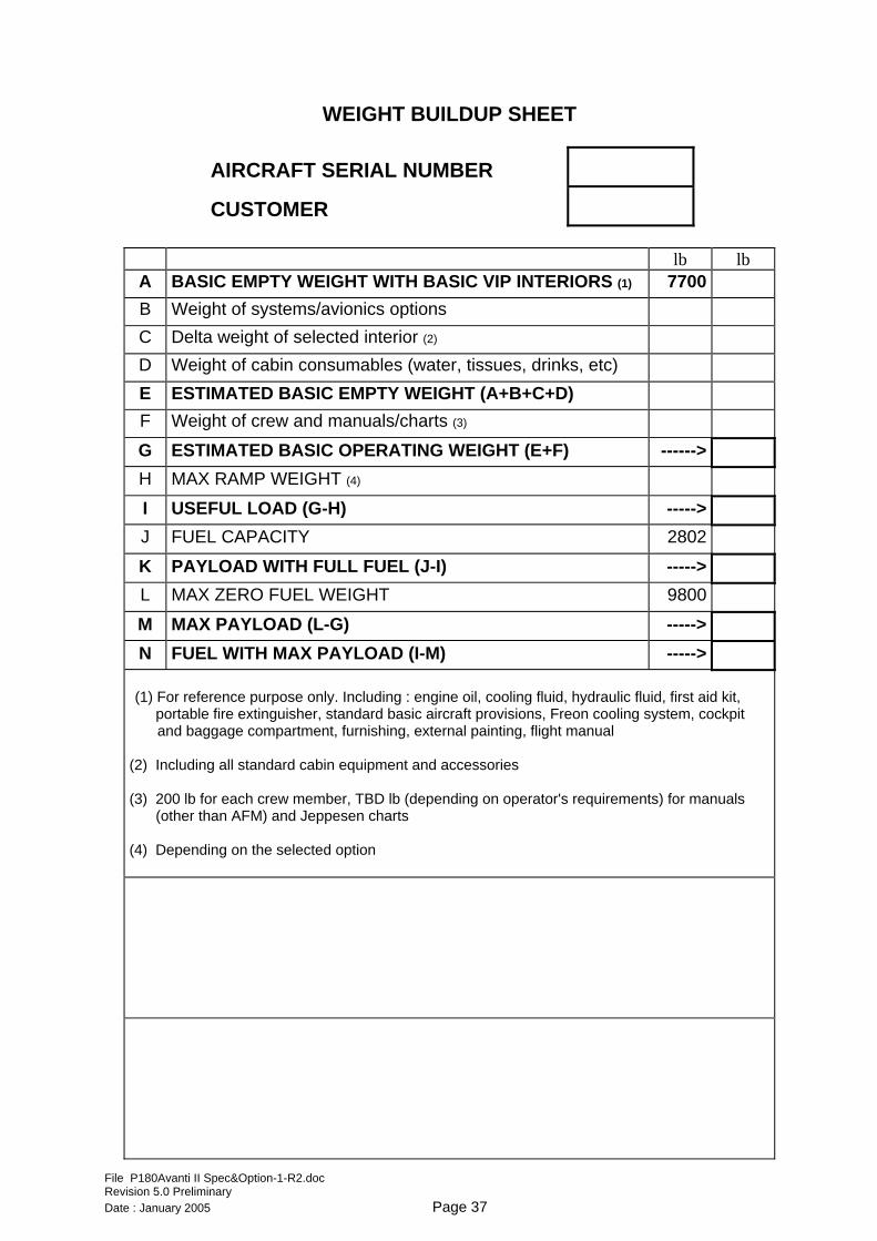
WEIGHT BUILDUP SHEET
AIRCRAFT SERIAL NUMBER
CUSTOMER
lb lb A BASIC EMPTY WEIGHT WITH BASIC VIP INTERIORS (1) 7700 B Weight of systems/avionics options C Delta weight of selected interior (2) D Weight of cabin consumables (water, tissues, drinks, etc) E ESTIMATED BASIC EMPTY WEIGHT (A+B+C+D) F Weight of crew and manuals/charts (3)
G ESTIMATED BASIC OPERATING WEIGHT (E+F) ------> H MAX RAMP WEIGHT (4)
I USEFUL LOAD (G-H) -----> J FUEL CAPACITY 2802
K PAYLOAD WITH FULL FUEL (J-I) -----> L MAX ZERO FUEL WEIGHT 9800
M MAX PAYLOAD (L-G) -----> N FUEL WITH MAX PAYLOAD (I-M) ----->
(1) For reference purpose only. Including : engine oil, cooling fluid, hydraulic fluid, first aid kit,
portable fire extinguisher, standard basic aircraft provisions, Freon cooling system, cockpit and baggage compartment, furnishing, external painting, flight manual (2) Including all standard cabin equipment and accessories (3) 200 lb for each crew member, TBD lb (depending on operator's requirements) for manuals
(other than AFM) and Jeppesen charts (4) Depending on the selected option
File P180Avanti II Spec&Option-1-R2.doc Revision 5.0 Preliminary Date : January 2005 Page 37
SECTION 1 STANDARD PASSENGER INTERIOR CONFIGURATIONS
All passenger interior configurations share the following elements: CABIN SHELLS One-piece headliner running the full cabin length from the forward partitions to the rear
pressure bulkhead One-piece sidewalls/window panels (1 each side) including window shades One-piece lower sidewalls/armrests (1 each side) Aft bulkhead cover Entry door cover
PASSENGER SERVICE UNIT (PSU) Drop-out oxygen masks at each seat location, including one mask in the lavatory area Air outlets and reading lights at each seat location Table lights Four speakers Indirect cabin lighting made up of:
• Straight fluorescent lamps both-sides-along cabin ceiling • Dim/bright selection • Switch on left partition at entrance • Individual switches on armrest inserts
STANDARD FORWARD CABINETS WITH PARTITIONS The passenger cabin is separated from the cockpit by two partitions incorporating small stowage cabinets: LH forward cabinet with partition includes:
RH forward cabinet with partition includes: • Jeppesen maps stowage provision • Smoke hood • One drawer
STANDARD REAR PARTITIONS LH aft partition between cabin and toilet compartment RH aft partition between cabin and toilet compartment including a sliding privacy door and
an advisory light (cabin side)
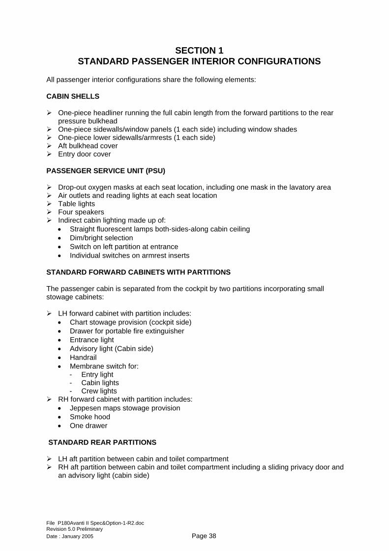
File P180Avanti II Spec&Option-1-R2.doc Revision 5.0 Preliminary Date : January 2005 Page 38
Fwd LH partition Fwd RH partition Rear partition and toilet compartment STANDARD TOILET COMPARTMENT The rear toilet compartment includes: Cabinet assembly vanity closet including:
• Containers and faucet for cold water • Illuminated mirror • Advisory light • Membrane switches • Illuminated wardrobe with coat hanger and door
• Self contained flushing toilet certified for use as a seat during take-off and landing • Seat restraint system including seat belt and shoulder harness with inertia reel • Seat and back cushions • Leather or fabric upholstering
File P180Avanti II Spec&Option-1-R2.doc Revision 5.0 Preliminary Date : January 2005 Page 39
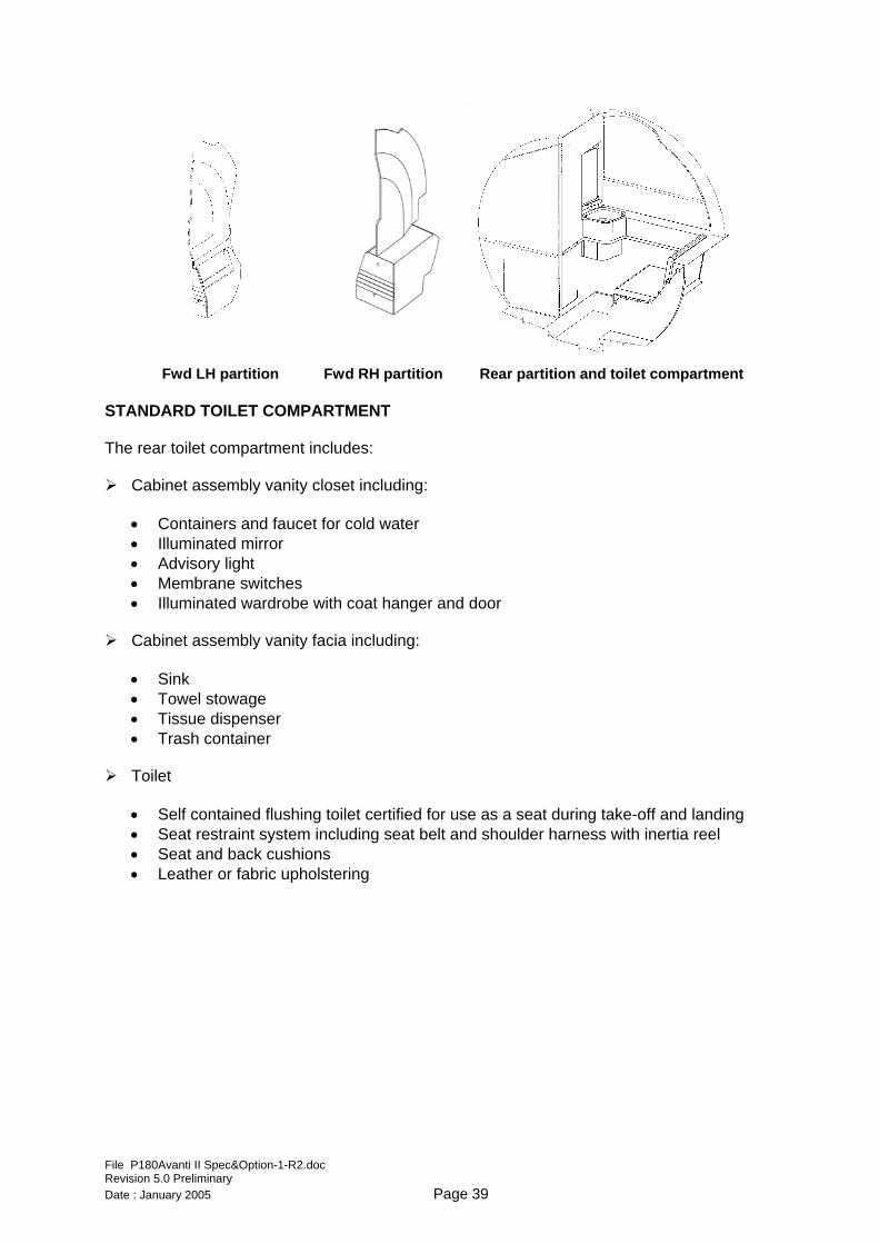
AVAILABLE CABIN LAYOUTS
BASIC CONFIGURATION Basic VIP
Standard cabin shells Standard Passenger Service Units (1 each side) customized to suit seat configuration Standard cabinets with partitions between cockpit and passenger cabin Standard aft partitions between passenger cabin and toilet area Four individual seats in Club configuration One two-place divan One one-place divan Two folding tables One refreshment center Standard Cabinet Assembly Vanity Closet Standard Cabinet Assembly Toilet Console Standard Cabinet Assembly Vanity Facia Toilet Miscellanea
File P180Avanti II Spec&Option-1-R2.doc Revision 5.0 Preliminary Date : January 2005 Page 40
File P180Avanti II Spec&Option-1-R2.doc Revision 5.0 Preliminary Date : January 2005 Page 41
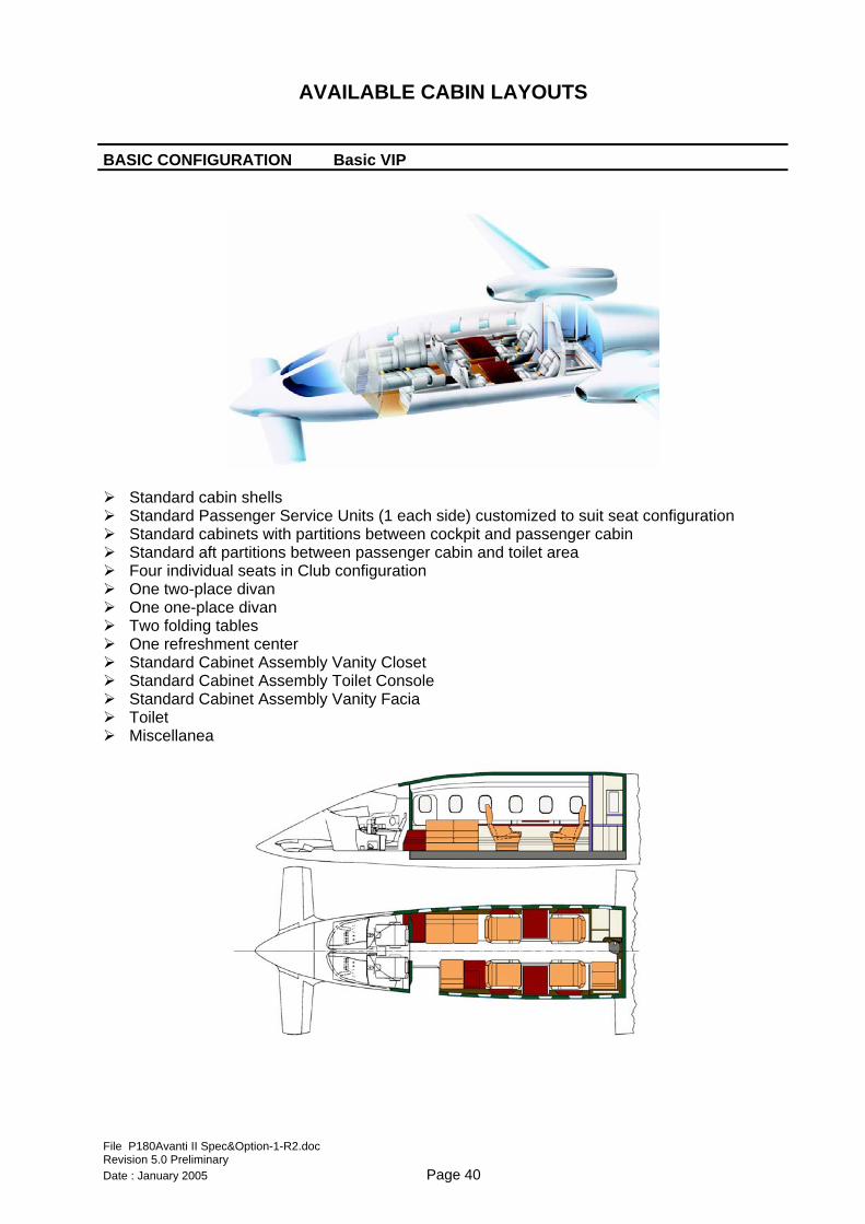
OPTION 1 Super VIP
(Six Seats Cabin Arrangement) I-001
Standard cabin shells Standard Passenger Service Units (1 each side) customized to suit seat configuration Standard cabinets with partitions between cockpit and passenger cabin Standard aft partitions between passenger cabin and toilet area Standard forward cabinets with partitions Standard rear partitions Four individual seats in Club configuration Two forward facing individual seats Two folding tables Two pyramids and one midship refreshment centres Standard Cabinet Assembly Vanity Closet Standard Cabinet Assembly Toilet Console Standard Cabinet Assembly Vanity Facia Toilet Miscellanea
File P180Avanti II Spec&Option-1-R2.doc Revision 5.0 Preliminary Date : January 2005 Page 42
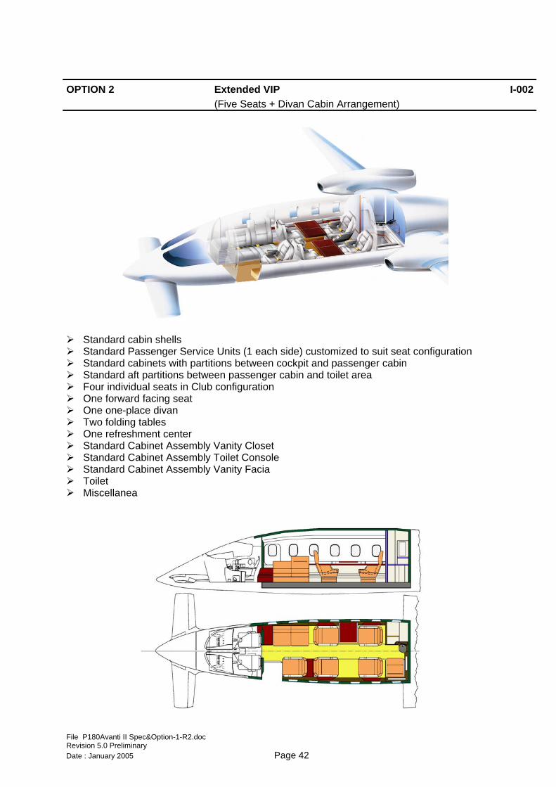
OPTION 2 Extended VIP
(Five Seats + Divan Cabin Arrangement) I-002
Standard cabin shells Standard Passenger Service Units (1 each side) customized to suit seat configuration Standard cabinets with partitions between cockpit and passenger cabin Standard aft partitions between passenger cabin and toilet area Four individual seats in Club configuration One forward facing seat One one-place divan Two folding tables One refreshment center Standard Cabinet Assembly Vanity Closet Standard Cabinet Assembly Toilet Console Standard Cabinet Assembly Vanity Facia Toilet Miscellanea
File P180Avanti II Spec&Option-1-R2.doc Revision 5.0 Preliminary Date : January 2005 Page 43
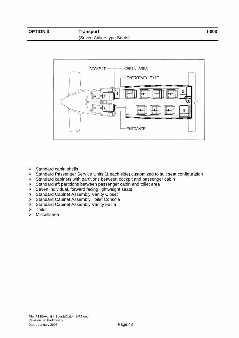
OPTION 3 Transport
(Seven Airline type Seats) I-003
Standard cabin shells Standard Passenger Service Units (1 each side) customized to suit seat configuration Standard cabinets with partitions between cockpit and passenger cabin Standard aft partitions between passenger cabin and toilet area Seven individual, forward facing lightweight seats Standard Cabinet Assembly Vanity Closet Standard Cabinet Assembly Toilet Console Standard Cabinet Assembly Vanity Facia Toilet Miscellanea
File P180Avanti II Spec&Option-1-R2.doc Revision 5.0 Preliminary Date : January 2005 Page 44
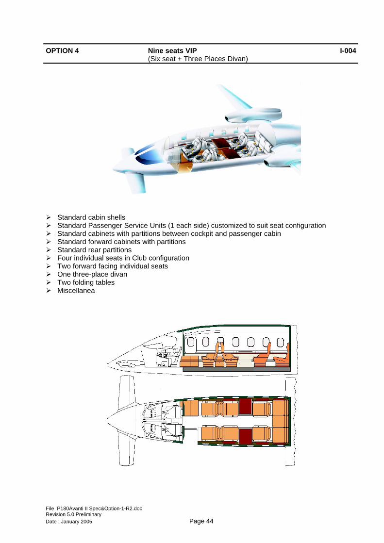
OPTION 4 Nine seats VIP
(Six seat + Three Places Divan) I-004
Standard cabin shells Standard Passenger Service Units (1 each side) customized to suit seat configuration Standard cabinets with partitions between cockpit and passenger cabin Standard forward cabinets with partitions Standard rear partitions Four individual seats in Club configuration Two forward facing individual seats One three-place divan Two folding tables Miscellanea
File P180Avanti II Spec&Option-1-R2.doc Revision 5.0 Preliminary Date : January 2005 Page 45
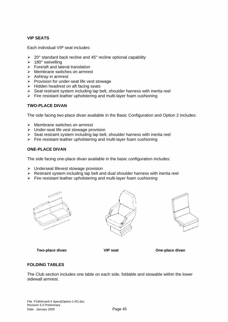
VIP SEATS Each individual VIP seat includes: 20° standard back recline and 45° recline optional capability 180° swivelling Fore/aft and lateral translation Membrane switches on armrest Ashtray in armrest Provision for under-seat life vest stowage Hidden headrest on aft facing seats Seat restraint system including lap belt, shoulder harness with inertia reel Fire resistant leather upholstering and multi-layer foam cushioning
TWO-PLACE DIVAN The side facing two-place divan available in the Basic Configuration and Option 2 includes: Membrane switches on armrest Under-seat life vest stowage provision Seat restraint system including lap belt, shoulder harness with inertia reel Fire resistant leather upholstering and multi-layer foam cushioning
ONE-PLACE DIVAN The side facing one-place divan available in the basic configuration includes: Underseat lifevest stowage provision Restraint system including lap belt and dual shoulder harness with inertia reel Fire resistant leather upholstering and multi-layer foam cushioning
Two-place divan VIP seat One-place divan FOLDING TABLES The Club section includes one table on each side, foldable and stowable within the lower sidewall armrest.
File P180Avanti II Spec&Option-1-R2.doc Revision 5.0 Preliminary Date : January 2005 Page 46
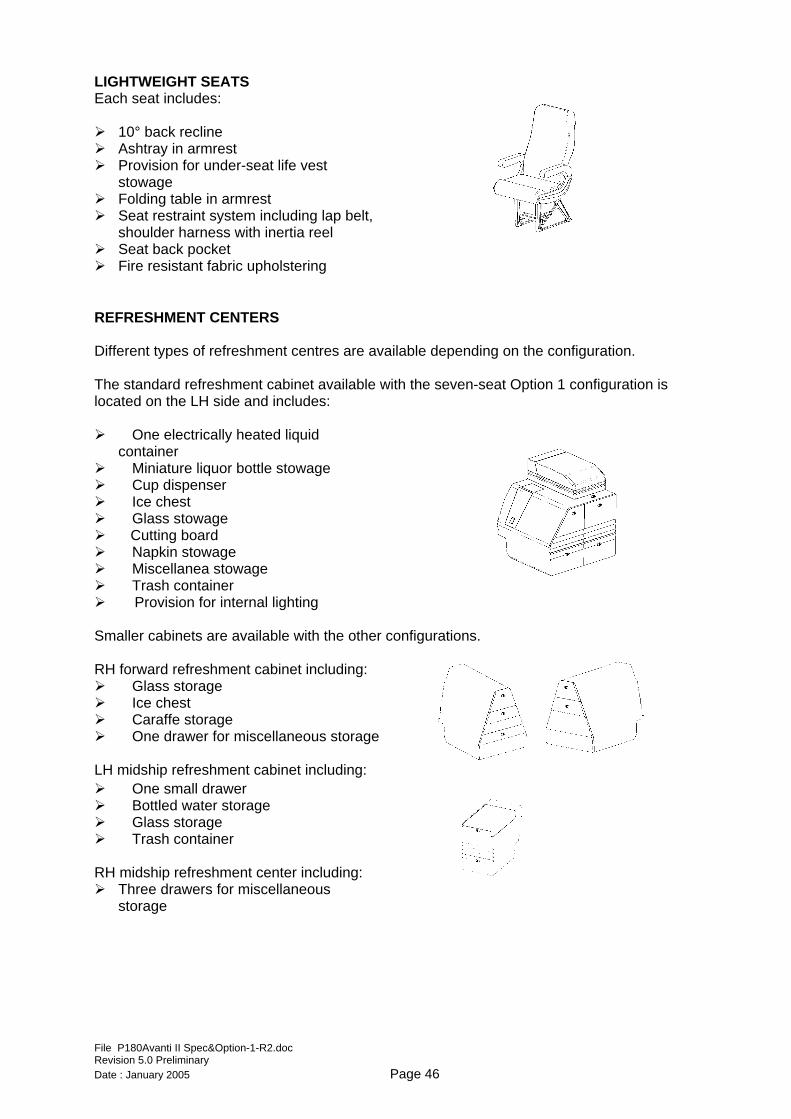
LIGHTWEIGHT SEATS Each seat includes: 10° back recline Ashtray in armrest Provision for under-seat life vest
stowage Folding table in armrest Seat restraint system including lap belt,
shoulder harness with inertia reel Seat back pocket Fire resistant fabric upholstering
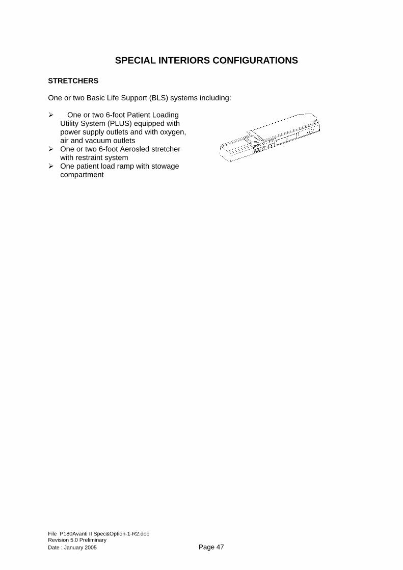
REFRESHMENT CENTERS Different types of refreshment centres are available depending on the configuration. The standard refreshment cabinet available with the seven-seat Option 1 configuration is located on the LH side and includes: One electrically heated liquid
Special materials and/or finishes may be provided on Customer’s request at an extra charge and with lead times to be defined case-by-case. Non standard materials may cause extra weight and a subsequent reduction of useful payload.
All upholstery materials must comply with the requirements of specification PS180-25-021 “Materials for aircraft furnishing”.
MISCELLANEA PROTECTIONS Protections are available to prevent damage during cargo handling for the lower sidewalls and for the inflatable door seal. CARGO RESTRAINT SYSTEM The cargo restraint system includes: Cargo nets Restraint straps Tiedown fittings
FLOOR CARPET Floor carpet made of fire-resistant material over the entire floor area.
File P180Avanti II Spec&Option-1-R2.doc Revision 5.0 Preliminary Date : January 2005 Page 49
SECTION 2 AVIONICS OPTIONS
DUAL ADF A-001
The Dual ADF option replaces the single ADF installation included in the P180 Avanti II basic configuration. Requires replacement of the basic Collins NAV-4500 VOR/ILS/MKR receiver with a second Collins NAV-4000 VOR/ILS/MKR/ADF receiver identical to the primary NAV receiver.
DUAL DME A-002
It provides an additional Collins DME-4000 receiver.
HF PROVISION A-003
It provides wiring and mounting provisions for later installation of the HF system.
HF SYSTEM A-004 The KHF 990 HF Radio Communication System can be added to the two VHF Communication Systems to perform long-distance voice communications. High Frequency radio communications allow reliable long range transmission and reception over distances of thousands of miles. This makes HF radio particularly useful when flying over vast surfaces where VHF communications, limited to line of sight transmission, are out of reach. The system operates from 2.0000 to 29.9999 MHz in AM and SSB and has a maximum output power of 150 W. The control panel provides: system tuning, either by selecting the desired frequency or by recalling stored channels (up
to 19) or preset channels (all 176 ITU maritime radiotelephone network channels are stored), operating mode selection such as LSB, USB and AM modes or A3J and A3A telephone
modes, frequency display, system monitoring and channel programming/setting.
Some indications may be affected during HF COM transmissions, such as: VOR and localizer indications, ADF, Torque and Engine Oil Pressure indications.
Note that the probe antenna measures about 2.5 m and is located in the fuselage tail. Special care must be taken during parking operations. The antenna can be removed/installed easily and rapidly. The kit includes: A KTR 993 HF transceiver located in the rear fuselage A KFS 594 HF/AM control unit located in the pedestal A KAC 992 antenna coupler A removable whip antenna extending from the tailcone
File P180Avanti II Spec&Option-1-R2.doc Revision 5.0 Preliminary Date : January 2005 Page 50
COCKPIT VOICE RECORDER A-005
The L3 Communications FA2100 Cockpit Voice Recorder allows recording of all audio signals: signals transmitted or received by the pilot and the copilot, cabin page announcements, cockpit conversations, through the cockpit area microphone
All audio inputs are fed into 120-minutes recording channels. The FA2100 is provided with an Underwater Locator Beacon (ULB). A g-switch enables to stop the record in case of impact. The kit includes: A CVR recording unit located in the baggage compartment A CVR control unit located in the pedestal A g-switch located in the vanity area close to the aircraft C.G. A cockpit microphone located on the pedestal RH side wall A CVR portable interface unit for ground checks only
The CVR is mandatory in the US for aircraft equipped with 6 or more passenger seats operating under FAR 135. DUAL MODE S TRANSPONDER A-006 It provides an additional Collins TDR-94D Mode S Transponder with ID, Diversity and Enhanced Surveillance capabilities identical to the single Mode S Transponder of the basic configuration. It requires an additional antenna on the top fuselage.
LIGHTNING DETECTION A-007 It provides an L3 Communications Stormscope lightning detection system able to detect various levels of lightning activity and to process that information into ARINC 429 format to be displayed on the AFDs. Lightning detection is generally limited to approximately 100 NM from the aircraft. Lightning data from the lightning detection system may be superimposed with weather radar data on those PFD and MFD formats which are weather radar compatible.
SATELLITE PHONE A-008
The AirCell ST3100 Iridium Satcom transceiver provides worldwide access to the Iridium global satellite network. The kit includes: An ST3100 transceiver unit located in the passenger cabin A patch antenna located on the top fuselage A cordless base station located in the passenger cabin A cordless handset providing voice communications, control functions and programming A remote dialler unit located in the pedestal and allowing the flight crew to access the
telephone system through the audio panels Two modified audio panels replacing the standard audio panels
File P180Avanti II Spec&Option-1-R2.doc Revision 5.0 Preliminary Date : January 2005 Page 51
UPGRADE FOR INTEGRATED FLIGHT INFORMATION SYSTEM A-009
Provisions for giving the capability to display maps (airways, airspace boundaries, geopolitical data), Jeppesen charts (airport charts, approach charts, en-route charts) or graphical weather on the Multi Function Display. It includes the installation of the following optional units: Collins AFD-3010E Enhanced Flight Display in place of the standard AFD-3010 in the
central position Collins FSU-5010 File Server Unit (FSU) Collins ECU-3000 External Compensation Unit Collins CPAS-3000 software for installation on a laptop PC
The image files can stored in the FSU.
ELECTRONIC CHARTS A-010
This option is offered as an add-on to option A-009 “Upgrade For Integrated Flight Information System”. It provides the capability to display Jeppesen charts (airport charts, approach charts, en-route charts) on the Multi Function Display It includes the installation of the following optional units: Collins ECH-5000 Electronic Charts Software
The Chart image files are stored in the FSU and are selected for display via the Chart Main Menu. The Control Panel provides an interface with the Chart Main Menu and is also used to manipulate the displayed chart. The chart feature also provides a depiction of the aircraft's current position on all charts that have been geographically referenced by Jeppesen. GPS position information is used to place a moving airplane symbol on the chart planview. It requires subscription to the Jeppesen Electronic Charts Service.
ENHANCED MAP OVERLAYS A-011
This option is offered as an add-on to option A-009 “Upgrade For Integrated Flight Information System”. It provides the capability to display geopolitical data, airways and airspace maps on the Multi Function Display. It includes the installation of the following additional software: Collins OVL-5000 Enhanced Map Overlays
Map displays are controlled via the Control Panel or via line select keys to access the Map Menu. In order to prevent display clutter, each of the enhanced map overlays is automatically removed as map range is increased. The airways and airspace depictions are removed when range is increased over 100nm. The geopolitical map data is removed when map range is increased over 300nm. It requires subscription to the Collins Map Service.
File P180Avanti II Spec&Option-1-R2.doc Revision 5.0 Preliminary Date : January 2005 Page 52
GRAPHICAL WEATHER A-012
This option is offered as an add-on to Option A-009 009 “Upgrade For Integrated Flight Information System”. It provides the capability to display weather information on the Multi Function Display. It includes the installation of the following additional units: Additional Collins VHF-4000 radio dedicated to ground-air Data Link for weather information
The Graphical Weather (GWx) Display is provided by Datalink GWx. The Datalink GWx system requires a third Collins VHF-4000 radio, CMU capability in the RIU, and a multifunction CDU. The File Server Unit has the capability to store uplinked graphical weather imagery and to display it on the MFD either as a dedicated graphical weather format or as a weather overlay on the Plan Map function. x PC DATA LOADER A-013The PC Data Loader allows data uploading and downloading (FMS updates, flight plans, maintenance and diagnostic data, etc.) to/from a laptop PC. The kit includes: A PCMCIA card equipped with connection cable
NOTE: not required if options A-010 is installed.
File P180Avanti II Spec&Option-1-R2.doc Revision 5.0 Preliminary Date : January 2005 Page 53
SECTION 3
SYSTEMS OPTIONS
ENGINE FIRE EXTINGUISHER S-001
The fire protection system installed on P180 Avanti II detects the presence of a fire or of a local overheat condition in the engine fire zones. The optional engine fire extinguishing system discharges extinguishing agent into the fire zones when it is activated by the flight crew. Two identical systems are installed, one for each engine. The fire bottles are carbon-halon steel containers attached to the engine mounting frames. The stainless steel tubes and nozzles duct the extinguishing agent to the gearbox zones and to the propeller gearbox zones. Two lighted pushbuttons are on the left and right glareshields. They are guarded to prevent inadvertent discharge of the fire bottles. The engine fire extinguishing system has been certified on a non-dangerous basis. No tests to demonstrate the extinguishing agent concentrations in nacelle zones have been carried out.
FIRST AID OXYGEN AND PBE S-002
First Aid Oxygen System: The First Aid Oxygen System consists of an additional outlet valve connected to the pilot main oxygen line. It is placed in a convenient location in the airplane cabin, depending on the type of airplane interior configuration. A medical oxygen mask with a metered two-flow selector provides oxygen flow at 2 lpm or at 4 lpm. It is available at any time during flight, by connecting the appropriate oxygen mask to the outlet valve. Protective Breathing Equipment (PBE): The Protective Breathing Equipment (or emergency escape hood) is installed close to the crew members. It provides automatic oxygen flow and smoke protection for one crew member in case of smoke detection or of presence of fire extinguishing agent in the cabin. The hood may be used during flight: at all cabin altitudes when the cabin pressurization control system is operative, up to 25000 ft cabin altitude when the cabin pressure control system is inoperative.
The oxygen container capacity is 39 liters. The smoke hood phoning membrane allows easy communications with the outside. NOTE: The current version (-805) is applicable to aircraft with the Basic VIP cabin configuration. Other versions must be developed to suit other cabin configurations.
File P180Avanti II Spec&Option-1-R2.doc Revision 5.0 Preliminary Date : January 2005 Page 54
PORTABLE OXYGEN CYLINDER S-003
The portable oxygen cylinder provides a supplementary oxygen source for crew and passengers use, if requested. The oxygen cylinder is installed inside the wardrobe, located in the vanity section. It is attached to the right side of the forward wall of the wardrobe. It supplies a constant flow of oxygen to the masks up to 16500 ft cabin altitude. The oxygen unit is provided with 2 masks, each equipped with a flow indicator. The table below gives the average duration in hours of a cylinder fully charged to 1800 psig, with respect to the cabin altitude.
PASSENGERS CABIN ALTITUDE
(Feet) 1 2
0 2.75 1.38 12500 3.03 1.52 16500 3.13 1.57
Oxygen Cylinder Duration (hours).
Use of supplementary oxygen is allowed only when the cabin is pressurized or when the cabin altitude is below 16500 ft. GRAVEL KIT S-004
The kit is installed on the nose landing gear to protect the aircraft lower fuselage and wings from small debris that may be thrown up by the nose landing gear during operations on unpaved runways. The kit is designed to allow operation on grass or compacted gravel runways with CBR > 15. It is not designed to allow operation on rough or unprepared strips with loose gravel. Performance degradation for take-off and landing are defined in the relevant sections of the Flight Manual. Operation from unpaved runways implies application of a factor 4 for the purpose of calculating the operational cycles of the landing gear.
File P180Avanti II Spec&Option-1-R2.doc Revision 5.0 Preliminary Date : January 2005 Page 55
APPENDICES
Appendix A - Notes about the 3-Lifting-Surface design Some additional considerations are given herein about the P.180 3-Lifting-Surface design. The P.180 Avanti II’s distinctive shape is not simply due to a styling research but to a specific intent to design an aircraft with the following specific features: a wide body, stand-up cabin, jet-like performance and turboprop fuel efficiency. After a deep aerodynamic analysis and several hundreds hours of wind tunnel tests, PIAGGIO engineers concluded that these goals could not be achieved with conventional aircraft configurations. The P.180 project developed therefore the following new features: PIAGGIO’s patented Three-Lifting-Surface
Configuration (3LSC) provides a 34% reduction in total wing area over conventional designs, thereby reducing weight and drag; A non-cylindrical, low-drag fuselage shape
developed through extensive wind tunnel testing to allow a large cabin cross section without a large drag penalty;
,
While its shape is radically different from other aircraft, there is much to the P.180 that pilots and maintenance personnel will find conventional and familiar: Well known and widely used systems; 90-percent aluminum construction; Conventional flight controls.
Thanks to this unique combination of innovation and tradition, you can enjoy the P.180’s outstanding performance and exceptional comfort, while flying with usual confidence thanks to the Avanti’s tested technologies and systems. The P.180’s unique 3LSC design includes a small forward wing, a high-aspect-ratio main wing and a small horizontal stabiliser on top of the conventional vertical stabiliser. This combination reduces drag by minimising the amount of downward force the horizontal stabiliser must produce to balance the nose-down pitching moment created by the main wing lift and pressure distribution acting aft of the centre of gravity.
In a conventional 2-surface configuration, this nose-down pitching moment, neutralised (trimmed) by a downward force generated by the “negative” lift, can be as much as 10% of the aircraft’s weight at cruise to as much as 20% during approach. The result is that the main wing must provide the lift to support 110% to 120% of the aircraft’s weight. The net effect is that the main wing must be larger than a wing required to support only the aircraft’s weight.
ML = Nose down pitching moment created by the main wing’s lift
LT = Negative trim lift required to neutralise main wing’s pitching moment
Conventional aircraft
The extra lift required by the main wing and the “negative” lift generated by the horizontal stabiliser produces additional induced drag (the drag associated with the generation of lift). This additional drag could be avoided if the aircraft’s weight were supported by the main wing only and the “negative” lift was not required. A larger wing leads also to an additional structural weight and profile drag (the drag associated with size). With the P.180’s 3LSC design (fig A-2), the small forward wing produces “positive” upward lift required to trim the nose-down pitching moment created by the main wing. The horizontal stabiliser, in cruise configuration, is producing negligible “positive” or “negative” lift. The total lift produced by the forward and main wing is basically all that is required to support the aircraft’s weight. This lower lift requirement results in less wing area, hence, lower profile drag, lower induced drag and lower structural weight.
File P180Avanti II Spec&Option-1-R2.doc Revision 5.0 Preliminary Date : January 2005 Page 56
W = Aircraft weight L = Lift = LF +LM + LTLF = Forward wing lift LM = Main wing lift T = Lift to trim aircraft (negligible)
3-Lifting-Surface design
Although the horizontal tail, in some configurations, can produce a small amount of “negative” lift, the drag and weight penalty are minimal while the benefits to controllability are substantial. When the main wing’s flaps are lowered to perform takeoff and landing operations the centre of lift moves even further aft (fig. A-3), creating a large nose-down pitching moment. The flap on the Avanti’s forward wing is programmed to extend the exact amount to provide the additional up-lift to balance out the nose-down moment created by the main wing flaps. The horizontal stabiliser with its conventional elevator allows the pilot precise pitch control.
With the pure canard (2-surface) configuration, pitch control is far more difficult and may require the weight and complexity of variable incidence plus elevators or flaps on the forward wing. The Avanti’s pitch control and stall characteristics are so conventional that the aircraft does not require a stick-pusher or stick-shaker as some conventional aircraft designs.
Main wing centre of lift moves aft with flap deflection. Forward wing flaps are programmed to provide additional lift required to balance the increased nose-down pitching moment.
Flap effect
File P180Avanti II Spec&Option-1-R2.doc Revision 5.0 Preliminary Date : January 2005 Page 57
Appendix B - Notes about operation in Hot and High conditions Some additional considerations are given here about the P.180 operation in "Hot and High" environmental conditions. The P.180 Avanti II is powered by two Pratt & Whitney of Canada PT6A-66-B free turbine turboprop engines flat rated at 850 SHP and two Hartzell five metal blade pusher propellers. The PT6A-66-B is a light-weight, free-turbine engine, with a maximum thermodynamic rating of 1,498 shaft horsepower: on the P.180 it has been flat rated to 850 shaft horsepower. Each engine utilises two independent turbine sections: one driving the compressor in the gas generator section and the second (a two-stage power turbine) driving the propeller shaft through a reduction gearbox. The free turbine design permits selection of propeller speed from a wide r.p.m. band to suit aircraft operation. The concept of Flat Rating is not new or exclusive to the gas turbine engine. Supercharged piston engines which are capable of producing almost constant power up to some critical altitude may be described as flat rated with respect to variation in ambient pressure. The gas turbine engine is by nature worse than a piston engine since the possible power output varies more rapidly according to ambient temperature. For example, it is estimated that the PT6 engine can produce more than twice as much power at -54°C as at +54°C. It is an aircraft characteristic, valid both for conventional aeroplanes and helicopters, that at a particular take-off weight, the power required for safe take-off has a comparatively slight variation depending on ambient conditions. A mismatch therefore arises between the needs of the aircraft and the capabilities of a gas turbine engine as ambient conditions vary. The possibility may arise that when environmental conditions are such that the engines could produce more power than the aircraft requires, engine power may be limited or flat rated, with saving in engine weight, particularly the output gearbox. The worst condition for turbine powered aircraft would be on a hot day when the engine develops the minimum amount of power.
Flat rated engines are operated in a manner that allows the maximum possible power on a hot day, yet holds the power developed on cooler days to this same maximum value for a hot day. This enables the engine to produce a constant amount of power, equal to the power rating of the engine, over a wide range of environmental temperatures without having to work the engine harder than is necessary at any time. Considering flat rating as it is applied to the PT6A-66 engine in actual operations, it should be pointed out that all the PT6A engines are flat rated, i.e. at low ambient temperatures mechanical limitations override thermodynamic considerations whereas at high ambient temperatures turbine inlet temperature limits prevail. Considering the ITT (Inter-Turbine Temperature) plotted against ambient temperature at constant power, on a 0°C day, it may be noticed that 850 SHP is available on a newly-overhauled engine at an ITT of only approximately 675°C. On a 57°C day, the ITT has reached 830°C and for higher temperatures is held constant by reducing SHP accordingly. So on the P.180 the rated power (850 SHP) is available up to 57°C intake temperature. In other words, the PT6A-66B engine installed on the P.180 (taking into account the losses due to installation and the "Charge Heating" i.e. the heating introduced by the inlet duct) will produce 850 SHP up to 57°C intake temperature. At fixed propeller speed, the torque pressure is therefore constant as well. This is due to mechanical gearbox limitation. If the intake temperature increase, the ITT required to produce 850 SHP increases until a temperature of 57°C is reached. This results in the maximum ITT (830°C): at intake temperatures above 57°C the power must be reduced following a constant turbine inlet temperature line, the equivalent ITT being 830°C. As a mere sample, the data relevant to the PT6A-66 engine (1485 SHP thermodynamic power) performance are summarised in the table below:
File P180Avanti II Spec&Option-1-R2.doc Revision 5.0 Preliminary Date : January 2005 Page 58
Standard Day Thermodynamic Performance (Seal level, Static, 2000 rpm propeller) ESHP SHP SFC Take-off Rating 1498 1414 .521 Max. Continuous Rating 1498 1414 .521 Maximum Climb 1420 1341 .527 Maximum Cruise 1420 1341 .527 Maximum Shaft Horsepower Performance (Seal level, Static, 2000 rpm propeller) ESHP SHP TORQUE SFC Take-off Rating 905 850 (1) 2233 .642 Max. Continuous Rating 905 850 (1) 2233 .642 Maximum Climb 905 850 (2) 2233 .641 Maximum Cruise 905 850 (2) 2233 .641 (1) Available to 62.2°C @ 2,000 r.p.m. propeller speed. Maximum intake temperature 57°C to take into account the heating of the inlet duct ("Charge heating"). (2) Available to 56.1°C @ 2,000 r.p.m. propeller speed. Notes: Take-off Rating is the maximum power certified for Take-off. Maximum Continuous Rating is the maximum power certified for continuous operation periods of
unrestricted duration. The rating may be used as required by operation necessity. Maximum Climb and Maximum Cruise are the maximum powers approved by Pratt & Whitney for climb
and cruise operation. In calculating Equivalent Shaft Horsepower (ESHP) it is assumed that 2.5 lb axial thrust is equivalent to
one shaft horsepower. Specific Fuel Consumption (SFC) [lb/ESHP/hr] is based on JP4 fuel.
In other words:
every engine loses power climbing from
sea level to altitude or if subject to an ambient temperature increase; a flat rated engine, i.e. an engine whose
power has been limited to a lower value than the thermodynamic power it can deliver, can be reset to the rated power while climbing or in case of an ambient temperature increase since an excess of thermodynamic power is available.
In the case of the PT6A-66 installed on the P.180:
the rated power (850 SHP) can be
maintained during cruise or climb to approximately 25,000 feet on a standard day;
the rated power (850 SHP) is available to 57°C intake temperature @ 2,000 r.p.m. propeller speed, sea level.
The design of the P.180 requires high power only at altitude to fly at high speed. The advantage of having a flat-rated engine can be summarised in the following points: from sea level to about 25,000 ft the
engine power is limited by the torque (gearbox): in these operating conditions, an excess of thermodynamic power is available to reset shaft power when necessary; the gearbox is designed to transmit the
rated power, so that it is lighter than that required to transmit the full thermodynamic power; there is no power reduction due to
operation from high altitude runways (up to 25,000 ft); there is no power reduction due to
operation at high ambient temperature
File P180Avanti II Spec&Option-1-R2.doc Revision 5.0 Preliminary Date : January 2005 Page 59
(up to 57°C intake temperature at sea level).
For example: during operation with Anti Icing system on, torque (i.e. power, if constant propeller speed is maintained) may decrease
by 20%, true airspeed 30 knots and fuel flow 10% approximately: nevertheless, since an excess of thermodynamic power is available, the original power can be reset only by an increase of fuel flow of about 30 lb/h/engine.
File P180Avanti II Spec&Option-1-R2.doc Revision 5.0 Preliminary Date : January 2005 Page 60
Appendix C – New Aircraft Warranty A. Aircraft Manufacturer’s Limited Warranty Manufacturer warrants that the Aircraft, at the time of its delivery from Manufacturer, shall be free from all defects in material and workmanship and from defects inherent in its design relative to the known state of the art at the time of such design. This warranty does not apply to Aircraft operated or maintained contrary to Manufacturer's service and flight manuals, as they may be in effect from time to time. Upon receipt of prompt written notification from the Customer, including satisfactory evidence of the defects and return of the defective part when possible, Manufacturer shall: 1. if the failure occurs either within the first
1,000 flight hours or 24 months after delivery to Buyer, whichever occurs earlier, either repair or replace any defective item (except engines referenced in paragraph B below).
2. if the failure occurs either within the first 1,000 flight hours or 24 months after delivery to Buyer, whichever occurs earlier, either repair or replace all defective items which are manufactured by Manufacturer or those which are manufactured by vendors to Manufacturer's detailed design specifications.
3. if the failure occurs both within the first 5,000 flight hours and within 60 months after delivery of the Aircraft to Buyer, either repair or replace any defective
fuselage, empennage, wing, or control surface.
B. Engines Warranted by Pratt & Whitney Engine warranty will start from the day of the final delivery of the aircraft by the Manufacturer to the Buyer and will be provided and administered by the engine manufacturer (Pratt & Whitney Canada Inc.). Specific details for the implementation of such warranty will be furnished to the Buyer by the Manufacturer upon delivery of the Aircraft. C. Avionics Warranted by Applicable Manufacturers The Avionics equipment and components are warranted by their respective manufacturers for varying periods of time. Buyer will receive any remaining life of those warranties in accordance with each respective manufacturer's warranty program starting from the date of final delivery of the aircraft by the Manufacturer to the Buyer. D) Labour Statement With regard to paragraphs A(1), A(2), and A(3) above, the repair or replacement of defective parts under this warranty will be made by or through any Avanti Authorised Service Centre without charge for parts and/or labour for removal, installation and/or actual repair of such defective parts.