PRODUCT DATA 63-2675-01 TB7100A1000 MultiPRO™ Multispeed and Multipurpose Thermostat FOR CONVENTIONAL, HEAT PUMP, FAN COIL AND PTAC SYSTEMS APPLICATION The TB7100A1000 MultiPRO™ Multispeed and Multipurpose Thermostat is an effortless, seven-day programmable or non- programmable thermostat that provides universal system compatibility, precise comfort control and is easy-to-program. The TB7100 provides temperature control for gas, oil, electric, heat pumps, PTACs, and fan coil equipment for the following types of applications: — 1H/1C conventional — Up to 2H/1C heat pump — 4 pipe fan coil (3 fan speeds) — 2 pipe fan coil (3 fan speeds) — 2 pipe fan coil with Auxiliary Heat (3 fan speeds) — PTAC (Hi, Lo fan speed) FEATURES • Large, clear display with backlight shows the current and set temperature and time—even in the dark. • Menu-driven programming make setup effortless. • Beautiful ergonomic design is smart and sophisticated to match your customers’ lifestyle. • Real-time clock keeps time during power failures and automatically updates to daylight savings. • “Saving Changes” notification lets you know when the schedule changes have been saved. • Change reminders let you know when to replace the batteries. • Holiday Override options allow you to override the program schedule, as desired. • Speedy same-schedule programming—no need to copy multiple days. • Armchair programming allows you to remove the thermostat from the wall for programming. • Programmable or non-programmable modes. • Remote setback input for occupancy sensors or timeclocks. • VersaSpeed™ fan ramping algorithm and fan reset algorithm (fan coil and PTAC applications). • Up to 3 fan speeds for fan coil and 2 speeds for PTAC applications. • Remote indoor air sensing option (20K ohm or 10K ohm). Contents Application ........................................................................ 1 Specifications ................................................................... 2 Ordering Information ........................................................ 2 Installation ........................................................................ 4 Wiring ............................................................................... 5 Installer Setup .................................................................. 11 Operation .......................................................................... 17 Troubleshooting (Table 12) ............................................... 23
Transcript
PRODUCT DATA
63-2675-01
TB7100A1000 MultiPRO™Multispeed and Multipurpose ThermostatFOR CONVENTIONAL, HEAT PUMP, FAN COIL AND PTAC SYSTEMS
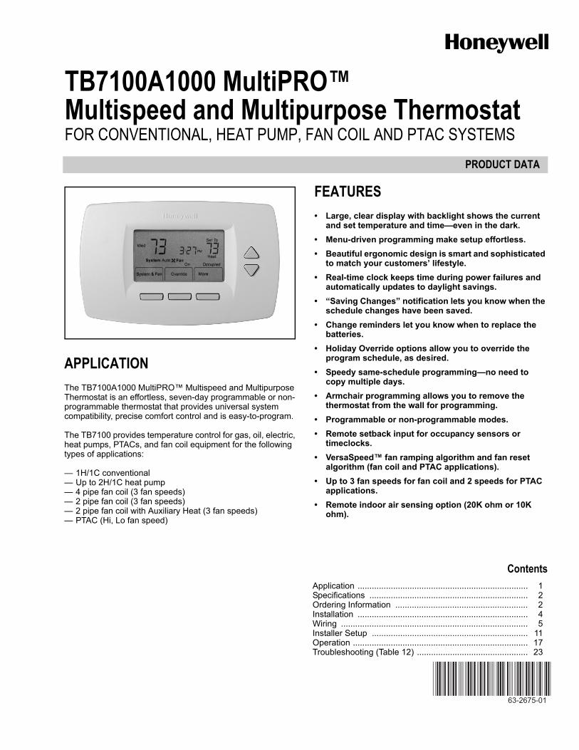
APPLICATIONThe TB7100A1000 MultiPRO™ Multispeed and Multipurpose Thermostat is an effortless, seven-day programmable or non-programmable thermostat that provides universal system compatibility, precise comfort control and is easy-to-program.
The TB7100 provides temperature control for gas, oil, electric, heat pumps, PTACs, and fan coil equipment for the following types of applications:
— 1H/1C conventional— Up to 2H/1C heat pump— 4 pipe fan coil (3 fan speeds)— 2 pipe fan coil (3 fan speeds)— 2 pipe fan coil with Auxiliary Heat (3 fan speeds)— PTAC (Hi, Lo fan speed)
FEATURES• Large, clear display with backlight shows the current
and set temperature and time—even in the dark.• Menu-driven programming make setup effortless.• Beautiful ergonomic design is smart and sophisticated
to match your customers’ lifestyle.• Real-time clock keeps time during power failures and
automatically updates to daylight savings.• “Saving Changes” notification lets you know when the
schedule changes have been saved.• Change reminders let you know when to replace the
batteries.• Holiday Override options allow you to override the
program schedule, as desired.• Speedy same-schedule programming—no need to
copy multiple days.• Armchair programming allows you to remove the
thermostat from the wall for programming.• Programmable or non-programmable modes.• Remote setback input for occupancy sensors or
timeclocks.• VersaSpeed™ fan ramping algorithm and fan reset
algorithm (fan coil and PTAC applications).• Up to 3 fan speeds for fan coil and 2 speeds for PTAC
applications.• Remote indoor air sensing option (20K ohm or 10K
TB7100A1000 MULTIPRO™ MULTISPEED AND MULTIPURPOSE THERMOSTAT
63-2675—01 2
ORDERING INFORMATIONWhen purchasing replacement and modernization products from your TRADELINE® wholesaler or distributor, refer to the TRADELINE® Catalog or price sheets for complete ordering number.
If you have additional questions, need further information, or would like to comment on our products or services, please write or phone:
1. Your local Honeywell Automation and Control Products Sales Office (check white pages of your phone directory).2. Honeywell Customer Care
1885 Douglas Drive NorthMinneapolis, Minnesota 55422-4386
In Canada—Honeywell Limited/Honeywell Limitée, 35 Dynamic Drive, Toronto, Ontario M1V 4Z9.International Sales and Service Offices in all principal cities of the world. Manufacturing in Australia, Canada, Finland, France, Germany, Japan, Mexico, Netherlands, Spain, Taiwan, United Kingdom, U.S.A.
SPECIFICATIONSThermostat Description: See Table 1.
Electrical Ratings: See Table 2.
Temperature:Ratings:
Operating Ambient:TB7100: 0°F to 120°F (-18°C to 49°C).C7189U: 5% to 95%.
Shipping: -30 °F to 150 °F (-34.4°C to 65.6°C).Display Accuracy: ±1°F (±0.5°C).Setpoint:
Range:Heating: 40°F to 90°F (4°C to 32°C).Cooling: 50°F to 99°F (10°C to 37°C).
Default Settings: See Table 3.
Humidity Ratings (RH, non-condensing):TB7100: 5% to 90%.C7189U: 5% to 95%.
Table 1. Thermostat Description.
Table 2. Electrical Ratings
Table 3. Energy Star Default Program Settings.
Cycle Rates (at 50% Load):Heating: Selectable 1 - 12 cycles per hour.Cooling: Selectable 1 - 6 cycles per hour.
Interstage Differential: Droopless control. Once the first stage is running at 90% load,
the thermostat energizes the second stage.
Cool Indication: Displays “Cool On” when Cool is activated.
Heat Indication: Displays “Heat On” when Heat is activated.
Auxiliary Heat Indication: Displays “Aux. Heat On” when Auxiliary Heat is activated.
Clock Accuracy: ±1 minute per month.
Finish:TB7100: Premier White® color.C7189U Wall Mount Remote Indoor Sensor: Premier White®
color.TR21 Wall Mount Remote Indoor Sensor: Premier White®
color.
Batteries:Two replaceable AA alkaline batteries: Power thermostat
when 24 Vac common is not used.Non-replaceable lithium battery with ten-year life: Under nor-
Calibration (TB7100, C7089U, C7189U, T7770A): No field calibration required.
Mounting Means:TB7100: Direct wall-mount using mounting screws and
anchors provided. Fits standard vertical or horizontal 2 in. x 4 in. junction box.
C7189U, TR21: Mounts directly on the wall using mounting screws and anchors provided. Fits a vertical 2 x 4 in. junc-tion box.
Cover Plate:32003796-001 Cover Plate is used to cover marks left on the
wall by the old thermostat.
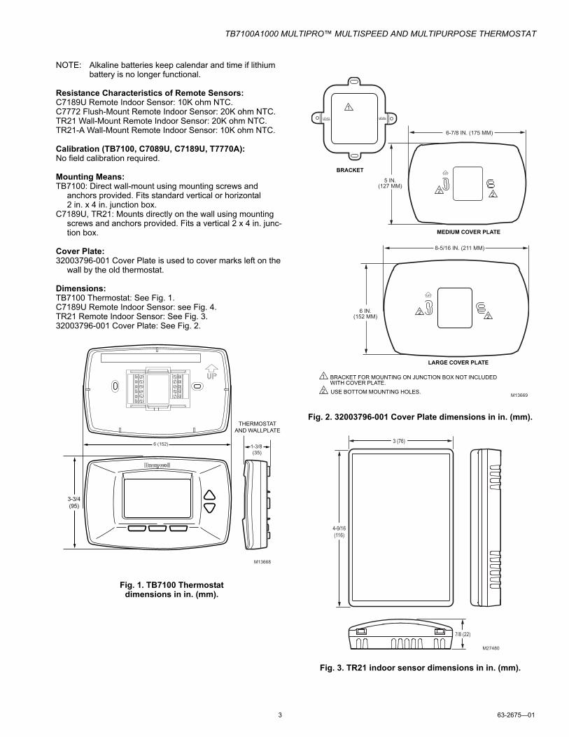
Dimensions:TB7100 Thermostat: See Fig. 1.C7189U Remote Indoor Sensor: see Fig. 4.TR21 Remote Indoor Sensor: See Fig. 3.32003796-001 Cover Plate: See Fig. 2.
Fig. 1. TB7100 Thermostat dimensions in in. (mm).
Fig. 2. 32003796-001 Cover Plate dimensions in in. (mm).
Fig. 3. TR21 indoor sensor dimensions in in. (mm).
M13668
3-3/4(95)
THERMOSTATAND WALLPLATE
1-3/8 (35)
6 (152)
LARGE COVER PLATE
BRACKET
LEVEL LEVEL
MEDIUM COVER PLATE
UP
6-7/8 IN. (175 MM)
UP
8-5/16 IN. (211 MM)
6 IN.(152 MM)
M13669
BRACKET FOR MOUNTING ON JUNCTION BOX NOT INCLUDED WITH COVER PLATE.
1
USE BOTTOM MOUNTING HOLES. 2
22
5 IN.(127 MM)
1
22
3 (76)
M27480
4-9/16(116)
7/8 (22)
TB7100A1000 MULTIPRO™ MULTISPEED AND MULTIPURPOSE THERMOSTAT
63-2675—01 4
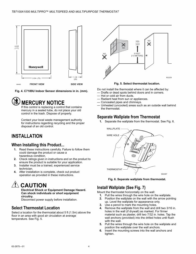
Fig. 4. C7189U Indoor Sensor dimensions in in. (mm).
MERCURY NOTICEIf this control is replacing a control that contains mercury in a sealed tube, do not place your old control in the trash. Dispose of properly.
Contact your local waste management authority for instructions regarding recycling and the proper disposal of an old control.
INSTALLATIONWhen Installing this Product...
1. Read these instructions carefully. Failure to follow them could damage the product or cause a hazardous condition.
2. Check ratings given in instructions and on the product to ensure the product is suitable for your application.
3. Installer must be a trained, experienced service technician.
4. After installation is complete, check out product operation as provided in these instructions.
CAUTIONElectrical Shock or Equipment Damage Hazard.Can shock individuals or short equipment circuitry.Disconnect power supply before installation.
Select Thermostat LocationSelect a location for the thermostat about 5 ft (1.5m) above the floor in an area with good air circulation at average temperature. See Fig. 5.
Fig. 5. Select thermostat location.
Do not install the thermostat where it can be affected by:— Drafts or dead spots behind doors and in corners.— Hot or cold air from ducts.— Radiant heat from sun or appliances.— Concealed pipes and chimneys.— Unheated (uncooled) areas such as an outside wall behind
the thermostat.
Separate Wallplate from Thermostat1. Separate the wallplate from the thermostat. See Fig. 6.
Fig. 6. Separate wallplate from thermostat.
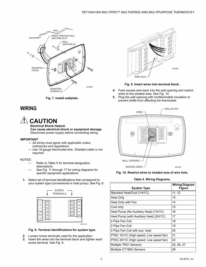
Install Wallplate (See Fig. 7)Mount the thermostat horizontally on the wall:
1. Pull the wires through the wire hole on the wallplate.2. Position the wallplate on the wall with the arrow pointing
up. Level the wallplate for appearance only.3. Use a pencil to mark the mounting holes.4. Remove the wallplate from the wall and drill two 3/16 in.
holes in the wall (if drywall) as marked. For firmer material such as plaster, drill two 7/32 in. holes. Tap the wall anchors (provided) into the drilled holes until flush with the wall.
5. Pull the wires through the wire hole on the wallplate and position the wallplate over the wall anchors.
6. Insert the mounting screws into the wall anchors and tighten.
M4465
4-5/8(117)
2-3/4 (70)1-1/8 (29)
FRONT VIEW SIDE VIEW
5 FEET[1.5 METERS]
YES
NO
M22258
NO
NO
THERMOSTAT
WIRE HOLE
M22267
WALLPLATE
TB7100A1000 MULTIPRO™ MULTISPEED AND MULTIPURPOSE THERMOSTAT
5 63-2675—01
Fig. 7. Install wallplate.
WIRING
CAUTIONElectrical Shock Hazard.Can cause electrical shock or equipment damage.Disconnect power supply before connecting wiring.
IMPORTANT— All wiring must agree with applicable codes,
ordinances and regulations.— Use 18 gauge thermostat wire. Shielded cable is not
required.
NOTES:— Refer to Table 5 for terminal designation
descriptions.— See Fig. 11 through 17 for wiring diagrams for
specific equipment applications.
1. Select set of terminal identifications that correspond to your system type (conventional or heat pump). See Fig. 8.
Fig. 8. Terminal identifications for system type.
2. Loosen screw terminals used for the application.3. Insert the wires into the terminal block and tighten each
screw terminal. See Fig. 9.
Fig. 9. Insert wires into terminal block.
4. Push excess wire back into the wall opening and restrict wires to the shaded area. See Fig. 10.
5. Plug the wall opening with nonflammable insulation to prevent drafts from affecting the thermostat.
Fig. 10. Restrict wires to shaded area of wire hole.
Table 4. Wiring Diagrams.
WALL
MOUNTING HOLES
M13665MOUNTING SCREWS (2)
WALL ANCHORS (2)
WIRES THROUGH WALLAND WIRE SLOT
M27415
CGY
O/BRCR
W1G2G3S1S2
SCREW TERMINALS
System TypeWiring Diagram
FigureStandard Heat/Cool (1H/1C) 11, 12Heat Only 13Heat Only with Fan 14Cool only 15Heat Pump (No Auxiliary Heat) (1H/1C) 16Heat Pump (with Auxiliary Heat) (2H/1C) 174 Pipe Fan Coil 182 Pipe Fan Coil 192 Pipe Fan Coil with aux. heat 20PTAC 1H/1C (High speed, Low speed fan) 21PTAC 2H/1C (High speed, Low speed fan) 22Multiple TR21 Sensors 25, 26, 27Multiple C7189U Sensors 28
M13666
WIRE HOLE
WALLPLATE
M22266
WALL OPENING
WIRE
SHADED AREA
TB7100A1000 MULTIPRO™ MULTISPEED AND MULTIPURPOSE THERMOSTAT
63-2675—01 6
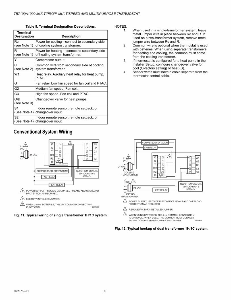
Table 5. Terminal Designation Descriptions. NOTES:1. When used in a single-transformer system, leave
metal jumper wire in place between Rc and R. If used on a two-transformer system, remove metal jumper wire between Rc and R.
2. Common wire is optional when thermostat is used with batteries. When using separate transformers for heating and cooling, the common must come from the cooling transformer.
3. If thermostat is configured for a heat pump in the Installer Setup, configure changeover valve for cool (O-factory setting) or heat (B).
4. Sensor wires must have a cable separate from the thermostat control cable.
Conventional System Wiring
Fig. 11. Typical wiring of single transformer 1H/1C system.
Fig. 12. Typical hookup of dual transformer 1H/1C system.
Terminal Designation DescriptionRc (see Note 1)
Power for cooling—connect to secondary side of cooling system transformer.
R (see Note 1)
Power for heating—connect to secondary side of heating system transformer.
Y Compressor output.C (see Note 2)
Common wire from secondary side of cooling system transformer.
W1 Heat relay. Auxiliary heat relay for heat pump, PTAC.
G Fan relay. Low fan speed for fan coil and PTAC.G2 Medium fan speed. Fan coil.G3 High fan speed. Fan coil and PTAC.O/B (see Note 3)
Changeover valve for heat pumps.
S1 (See Note 4)
Indoor remote sensor, remote setback, or changeover input.
S2 (See Note 4)
Indoor remote sensor, remote setback, or changeover input.
POWER SUPPLY. PROVIDE DISCONNECT MEANS AND OVERLOAD PROTECTION AS REQUIRED.
FACTORY INSTALLED JUMPER.
WHEN USING BATTERIES, THE 24V COMMON CONNECTION IS OPTIONAL.
1
2
3
CGY
O/BRCR
W1G2G3S1S2
2
3 L1 (HOT)
L2
1
24 VAC
M27416
HEAT RELAY
COMPRESSOR CONTACTOR
M27417
HEAT RELAY
FAN RELAY
COOLINGTRANSFORMER
HEATINGTRANSFORMER
POWER SUPPLY. PROVIDE DISCONNECT MEANS AND OVERLOAD PROTECTION AS REQUIRED.
REMOVE FACTORY INSTALLED JUMPER.
WHEN USING BATTERIES, THE 24V COMMON CONNECTION IS OPTIONAL. WHEN USED, THE COMMON MUST CONNECT TO THE COOLING TRANSFORMER SECONDARY.
1
3
2
3
L1 (HOT)
L2
1
24 VAC
L1 (HOT)
L2
1
24 VAC
CGY
O/BRCR 2
INDOOR TEMPERATURESENSOR/REMOTE
SETBACK
W1G2G3S1S2
TB7100A1000 MULTIPRO™ MULTISPEED AND MULTIPURPOSE THERMOSTAT
7 63-2675—01
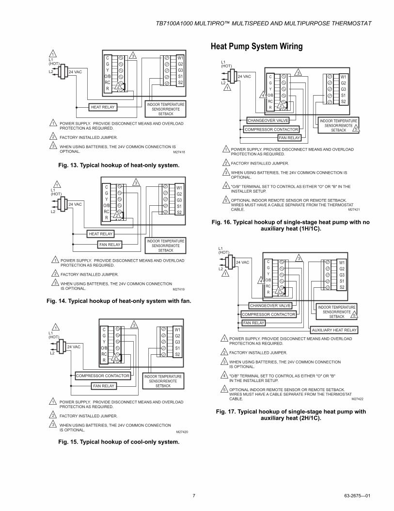
Fig. 13. Typical hookup of heat-only system.
Fig. 14. Typical hookup of heat-only system with fan.
Fig. 15. Typical hookup of cool-only system.
Heat Pump System Wiring
Fig. 16. Typical hookup of single-stage heat pump with no auxiliary heat (1H/1C).
Fig. 17. Typical hookup of single-stage heat pump with auxiliary heat (2H/1C).
M27418
HEAT RELAY
POWER SUPPLY. PROVIDE DISCONNECT MEANS AND OVERLOAD PROTECTION AS REQUIRED.
FACTORY INSTALLED JUMPER.
WHEN USING BATTERIES, THE 24V COMMON CONNECTION IS OPTIONAL.
1
2
3
L1 (HOT)
L2
1
24 VAC
CGY
O/BRCR 2
W1G2G3S1S2
INDOOR TEMPERATURESENSOR/REMOTE
SETBACK
3
M27419
HEAT RELAY
FAN RELAY
POWER SUPPLY. PROVIDE DISCONNECT MEANS AND OVERLOAD PROTECTION AS REQUIRED.
FACTORY INSTALLED JUMPER.
WHEN USING BATTERIES, THE 24V COMMON CONNECTION IS OPTIONAL.
1
2
3
3
L1 (HOT)
L2
1
24 VAC
2
CGY
O/BRCR
W1G2G3S1S2
INDOOR TEMPERATURESENSOR/REMOTE
SETBACK
M27420
FAN RELAY
POWER SUPPLY. PROVIDE DISCONNECT MEANS AND OVERLOAD PROTECTION AS REQUIRED.
FACTORY INSTALLED JUMPER.
WHEN USING BATTERIES, THE 24V COMMON CONNECTION IS OPTIONAL.
1
3
2
3
COMPRESSOR CONTACTOR
L1 (HOT)
L2
1
24 VAC
2
CGY
O/BRCR
W1G2G3S1S2
INDOOR TEMPERATURESENSOR/REMOTE
SETBACK
INDOOR TEMPERATURESENSOR/REMOTE
SETBACKCOMPRESSOR CONTACTOR
M27421
CHANGEOVER VALVE
1
2
3
4
5
FAN RELAY
POWER SUPPLY. PROVIDE DISCONNECT MEANS AND OVERLOAD PROTECTION AS REQUIRED.
FACTORY INSTALLED JUMPER.
WHEN USING BATTERIES, THE 24V COMMON CONNECTION IS OPTIONAL.
"O/B" TERMINAL SET TO CONTROL AS EITHER "O" OR "B" IN THE INSTALLER SETUP.
OPTIONAL INDOOR REMOTE SENSOR OR REMOTE SETBACK. WIRES MUST HAVE A CABLE SEPARATE FROM THE THERMOSTAT CABLE.
3
L1 (HOT)
L2 1
24 VAC
5
CGY
O/BRCR
4
2
W1G2G3S1S2
COMPRESSOR CONTACTOR
M27422
CHANGEOVER VALVE
1
2
3
4
5
FAN RELAY
POWER SUPPLY. PROVIDE DISCONNECT MEANS AND OVERLOAD PROTECTION AS REQUIRED.
FACTORY INSTALLED JUMPER.
WHEN USING BATTERIES, THE 24V COMMON CONNECTION IS OPTIONAL.
"O/B" TERMINAL SET TO CONTROL AS EITHER "O" OR "B" IN THE INSTALLER SETUP.
OPTIONAL INDOOR REMOTE SENSOR OR REMOTE SETBACK. WIRES MUST HAVE A CABLE SEPARATE FROM THE THERMOSTAT CABLE.
3
L1 (HOT)
L2 1
24 VAC
AUXILIARY HEAT RELAY
4
2
INDOOR TEMPERATURESENSOR/REMOTE
SETBACK 5
CGY
O/BRCR
W1G2G3S1S2
TB7100A1000 MULTIPRO™ MULTISPEED AND MULTIPURPOSE THERMOSTAT
63-2675—01 8
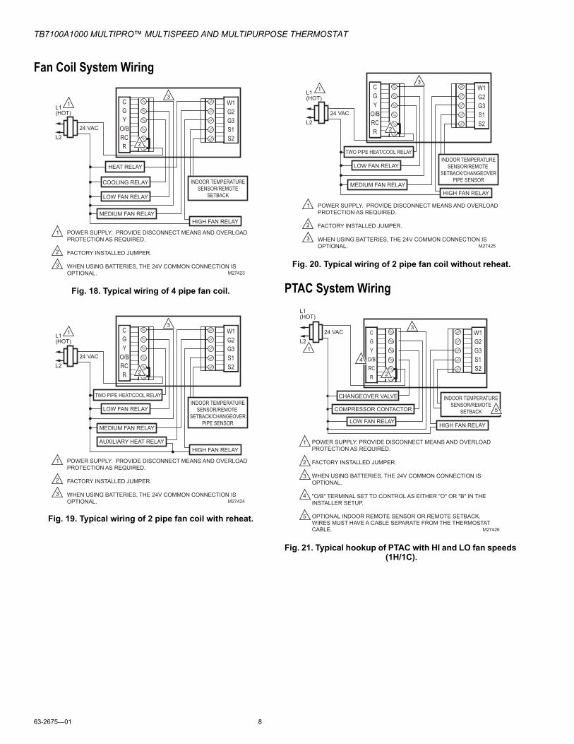
Fan Coil System Wiring
Fig. 18. Typical wiring of 4 pipe fan coil.
Fig. 19. Typical wiring of 2 pipe fan coil with reheat.
Fig. 20. Typical wiring of 2 pipe fan coil without reheat.
PTAC System Wiring
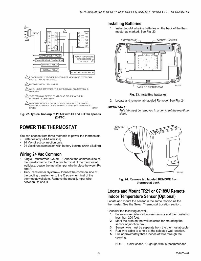
Fig. 21. Typical hookup of PTAC with HI and LO fan speeds (1H/1C).
COOLING RELAY INDOOR TEMPERATURESENSOR/REMOTE
SETBACK
HEAT RELAY
LOW FAN RELAY
POWER SUPPLY. PROVIDE DISCONNECT MEANS AND OVERLOAD PROTECTION AS REQUIRED.
FACTORY INSTALLED JUMPER.
WHEN USING BATTERIES, THE 24V COMMON CONNECTION IS OPTIONAL.
1
2
3
CGY
O/BRCR
W1G2G3S1S2
2
3
L1 (HOT)
L2
1
24 VAC
M27423
HIGH FAN RELAYMEDIUM FAN RELAY
INDOOR TEMPERATURESENSOR/REMOTE
SETBACK/CHANGEOVERPIPE SENSOR
TWO PIPE HEAT/COOL RELAY
LOW FAN RELAY
POWER SUPPLY. PROVIDE DISCONNECT MEANS AND OVERLOAD PROTECTION AS REQUIRED.
FACTORY INSTALLED JUMPER.
WHEN USING BATTERIES, THE 24V COMMON CONNECTION IS OPTIONAL.
1
2
3
CGY
O/BRCR
W1G2G3S1S2
2
3
L1 (HOT)
L2
1
24 VAC
M27424
HIGH FAN RELAYAUXILIARY HEAT RELAY
MEDIUM FAN RELAY
INDOOR TEMPERATURESENSOR/REMOTE
SETBACK/CHANGEOVERPIPE SENSOR
TWO PIPE HEAT/COOL RELAY
LOW FAN RELAY
POWER SUPPLY. PROVIDE DISCONNECT MEANS AND OVERLOAD PROTECTION AS REQUIRED.
FACTORY INSTALLED JUMPER.
WHEN USING BATTERIES, THE 24V COMMON CONNECTION IS OPTIONAL.
1
2
3
CGY
O/BRCR
W1G2G3S1S2
2
3
L1 (HOT)
L2
1
24 VAC
M27425
HIGH FAN RELAYMEDIUM FAN RELAY
INDOOR TEMPERATURESENSOR/REMOTE
SETBACKCOMPRESSOR CONTACTOR
M27426
CHANGEOVER VALVE
1
2
3
4
5
LOW FAN RELAY
POWER SUPPLY. PROVIDE DISCONNECT MEANS AND OVERLOAD PROTECTION AS REQUIRED.
FACTORY INSTALLED JUMPER.
WHEN USING BATTERIES, THE 24V COMMON CONNECTION IS OPTIONAL.
"O/B" TERMINAL SET TO CONTROL AS EITHER "O" OR "B" IN THE INSTALLER SETUP.
OPTIONAL INDOOR REMOTE SENSOR OR REMOTE SETBACK. WIRES MUST HAVE A CABLE SEPARATE FROM THE THERMOSTAT CABLE.
3
L1 (HOT)
L2 1
24 VAC
5
CGY
O/BRCR
4
2
W1G2G3S1S2
HIGH FAN RELAY
TB7100A1000 MULTIPRO™ MULTISPEED AND MULTIPURPOSE THERMOSTAT
9 63-2675—01
Fig. 22. Typical hookup of PTAC with HI and LO fan speeds (2H/1C).
POWER THE THERMOSTATYou can choose from three methods to power the thermostat:• Batteries only (AAA alkaline).• 24 Vac direct connection only.• 24 Vac direct connection with battery backup (AAA alkaline).
Wiring 24 Vac Common• Single-Transformer System—Connect the common side of
the transformer to the C screw terminal of the thermostat wallplate. Leave the metal jumper wire in place between Rc and R.
• Two-Transformer System—Connect the common side of the cooling transformer to the C screw terminal of the thermostat wallplate. Remove the metal jumper wire between Rc and R.
Installing Batteries1. Install two AA alkaline batteries on the back of the ther-
mostat as marked. See Fig. 23.
Fig. 23. Installing batteries.
2. Locate and remove tab labeled Remove. See Fig. 24.
IMPORTANTThis tab must be removed in order to set the real-time clock.
Fig. 24. Remove tab labeled REMOVE from thermostat back.
Locate and Mount TR21 or C7189U Remote Indoor Temperature Sensor (Optional)Locate and mount the sensor in the same fashion as the thermostat. See the Select Thermostat Location section.
Consider the following as well:1. Be sure wire distance between sensor and thermostat is
less than 200 feet.2. Mark the area on the wall selected for mounting the
sensor or junction box.3. Sensor wire must be separate from the thermostat cable.4. Run wire cable to a hole at the selected wall location.5. Pull approximately three inches of wire through the
opening.
NOTE: Color-coded, 18-gauge wire is recommended.
COMPRESSOR CONTACTOR
M27427
CHANGEOVER VALVE
1
2
3
4
5
LOW FAN RELAY
POWER SUPPLY. PROVIDE DISCONNECT MEANS AND OVERLOAD PROTECTION AS REQUIRED.
FACTORY INSTALLED JUMPER.
WHEN USING BATTERIES, THE 24V COMMON CONNECTION IS OPTIONAL.
"O/B" TERMINAL SET TO CONTROL AS EITHER "O" OR "B" IN THE INSTALLER SETUP.
OPTIONAL INDOOR REMOTE SENSOR OR REMOTE SETBACK. WIRES MUST HAVE A CABLE SEPARATE FROM THE THERMOSTAT CABLE.
3
L1 (HOT)
L2 1
24 VAC
AUXILIARY HEAT RELAY
4
2
INDOOR TEMPERATURESENSOR/REMOTE
SETBACK 5
CGY
O/BRCR
W1G2G3S1S2
HIGH FAN RELAY
M22259BACK OF THERMOSTAT
BATTERY HOLDERBATTERIES (2)
REMOVE TAB
RE
MO
VE
DU
RIN
G
INS
TA
LL
AT
ION
M22260
RE
MO
VE
DU
RIN
G
INS
TA
LL
AT
ION
TB7100A1000 MULTIPRO™ MULTISPEED AND MULTIPURPOSE THERMOSTAT
63-2675—01 10
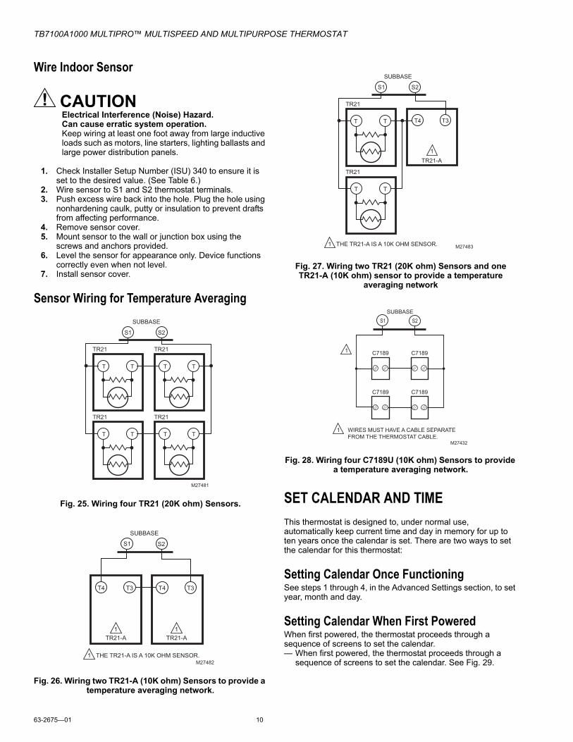
Wire Indoor Sensor
CAUTIONElectrical Interference (Noise) Hazard.Can cause erratic system operation.Keep wiring at least one foot away from large inductive loads such as motors, line starters, lighting ballasts and large power distribution panels.
1. Check Installer Setup Number (ISU) 340 to ensure it is set to the desired value. (See Table 6.)
2. Wire sensor to S1 and S2 thermostat terminals.3. Push excess wire back into the hole. Plug the hole using
nonhardening caulk, putty or insulation to prevent drafts from affecting performance.
4. Remove sensor cover.5. Mount sensor to the wall or junction box using the
screws and anchors provided.6. Level the sensor for appearance only. Device functions
correctly even when not level.7. Install sensor cover.
Sensor Wiring for Temperature Averaging
Fig. 25. Wiring four TR21 (20K ohm) Sensors.
Fig. 26. Wiring two TR21-A (10K ohm) Sensors to provide a temperature averaging network.
Fig. 27. Wiring two TR21 (20K ohm) Sensors and one TR21-A (10K ohm) sensor to provide a temperature
averaging network
Fig. 28. Wiring four C7189U (10K ohm) Sensors to provide a temperature averaging network.
SET CALENDAR AND TIMEThis thermostat is designed to, under normal use, automatically keep current time and day in memory for up to ten years once the calendar is set. There are two ways to set the calendar for this thermostat:
Setting Calendar Once FunctioningSee steps 1 through 4, in the Advanced Settings section, to set year, month and day.
Setting Calendar When First PoweredWhen first powered, the thermostat proceeds through a sequence of screens to set the calendar.— When first powered, the thermostat proceeds through a
sequence of screens to set the calendar. See Fig. 29.
M27481
S1 S2
T T
SUBBASE
TR21
T T
TR21
T T
TR21
T T
TR21
M27482
S1 S2
SUBBASE
TR21-A
T4 T3
TR21-A
T4 T3
1
11
THE TR21-A IS A 10K OHM SENSOR.
M27483
T4 T3
TR21-A
1
1
THE TR21-A IS A 10K OHM SENSOR.
S1 S2
T T
SUBBASE
TR21
T T
TR21
M27432
WIRES MUST HAVE A CABLE SEPARATE FROM THE THERMOSTAT CABLE.
1
1 C7189 C7189
C7189 C7189
SUBBASE S1 S2
TB7100A1000 MULTIPRO™ MULTISPEED AND MULTIPURPOSE THERMOSTAT
11 63-2675—01
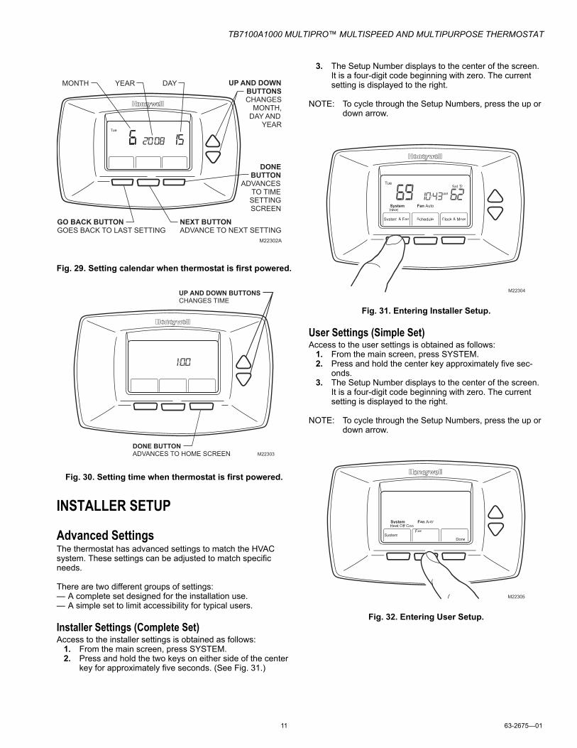
Fig. 29. Setting calendar when thermostat is first powered.
Fig. 30. Setting time when thermostat is first powered.
INSTALLER SETUP
Advanced SettingsThe thermostat has advanced settings to match the HVAC system. These settings can be adjusted to match specific needs.
There are two different groups of settings:— A complete set designed for the installation use.— A simple set to limit accessibility for typical users.
Installer Settings (Complete Set)Access to the installer settings is obtained as follows:
1. From the main screen, press SYSTEM. 2. Press and hold the two keys on either side of the center
key for approximately five seconds. (See Fig. 31.)
3. The Setup Number displays to the center of the screen. It is a four-digit code beginning with zero. The current setting is displayed to the right.
NOTE: To cycle through the Setup Numbers, press the up or down arrow.
Fig. 31. Entering Installer Setup.
User Settings (Simple Set)Access to the user settings is obtained as follows:
1. From the main screen, press SYSTEM. 2. Press and hold the center key approximately five sec-
onds.3. The Setup Number displays to the center of the screen.
It is a four-digit code beginning with zero. The current setting is displayed to the right.
NOTE: To cycle through the Setup Numbers, press the up or down arrow.
Fig. 32. Entering User Setup.
M22302A
MONTH YEAR DAY
GO BACK BUTTON
GOES BACK TO LAST SETTING NEXT BUTTON
ADVANCE TO NEXT SETTING
DONE
BUTTON
ADVANCES TO TIME
SETTING SCREEN
UP AND DOWN
BUTTONS
CHANGES MONTH,
DAY AND YEAR
DeSelect Day System & Fan
FanUseEdit Schedule
View Clock & More
Tue
DONE BUTTON
ADVANCES TO HOME SCREEN
UP AND DOWN BUTTONS
CHANGES TIME
M22303
ViewClock & More
System & Fan Schedule Clock & More
Fan Auto
Tue
System AutoHeat Off Cool
Set To
M22304
System & FanFanUseEdit
CancelDone
Fan AutoSystem AutoEm Heat Off Cool
M22305
TB7100A1000 MULTIPRO™ MULTISPEED AND MULTIPURPOSE THERMOSTAT
63-2675—01 12
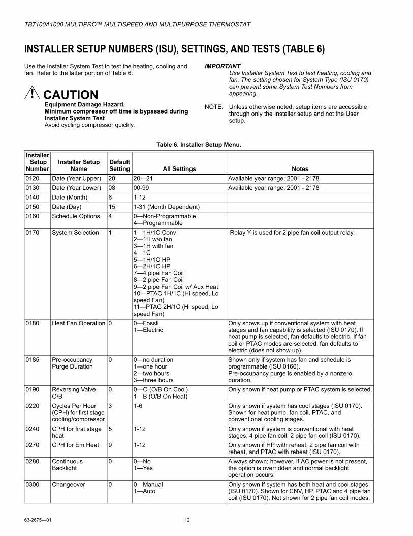
INSTALLER SETUP NUMBERS (ISU), SETTINGS, AND TESTS (TABLE 6)Use the Installer System Test to test the heating, cooling and fan. Refer to the latter portion of Table 6.
CAUTIONEquipment Damage Hazard.Minimum compressor off time is bypassed during Installer System TestAvoid cycling compressor quickly.
IMPORTANTUse Installer System Test to test heating, cooling and fan. The setting chosen for System Type (ISU 0170) can prevent some System Test Numbers from appearing.
NOTE: Unless otherwise noted, setup items are accessible through only the Installer setup and not the User setup.
Table 6. Installer Setup Menu.
Installer Setup
NumberInstaller Setup
NameDefault Setting All Settings Notes
0120 Date (Year Upper) 20 20—21 Available year range: 2001 - 21780130 Date (Year Lower) 08 00-99 Available year range: 2001 - 21780140 Date (Month) 6 1-120150 Date (Day) 15 1-31 (Month Dependent)0160 Schedule Options 4 0—Non-Programmable
4—Programmable0170 System Selection 1— 1—1H/1C Conv
2—1H w/o fan3—1H with fan4—1C5—1H/1C HP6—2H/1C HP7—4 pipe Fan Coil8—2 pipe Fan Coil9—2 pipe Fan Coil w/ Aux Heat10—PTAC 1H/1C (Hi speed, Lo speed Fan)11—PTAC 2H/1C (Hi speed, Lo speed Fan)
Relay Y is used for 2 pipe fan coil output relay.
0180 Heat Fan Operation 0 0—Fossil1—Electric
Only shows up if conventional system with heat stages and fan capability is selected (ISU 0170). If heat pump is selected, fan defaults to electric. If fan coil or PTAC modes are selected, fan defaults to electric (does not show up).
0185 Pre-occupancy Purge Duration
0 0—no duration1—one hour2—two hours3—three hours
Shown only if system has fan and schedule is programmable (ISU 0160).Pre-occupancy purge is enabled by a nonzero duration.
0190 Reversing Valve O/B
0 0—O (O/B On Cool)1—B (O/B On Heat)
Only shown if heat pump or PTAC system is selected.
0220 Cycles Per Hour (CPH) for first stage cooling/compressor
3 1-6 Only shown if system has cool stages (ISU 0170). Shown for heat pump, fan coil, PTAC, and conventional cooling stages.
0240 CPH for first stage heat
5 1-12 Only shown if system is conventional with heat stages, 4 pipe fan coil, 2 pipe fan coil (ISU 0170).
0270 CPH for Em Heat 9 1-12 Only shown if HP with reheat, 2 pipe fan coil with reheat, and PTAC with reheat (ISU 0170).
0280 Continuous Backlight
0 0—No1—Yes
Always shown; however, if AC power is not present, the option is overridden and normal backlight operation occurs.
0300 Changeover 0 0—Manual1—Auto
Only shown if system has both heat and cool stages (ISU 0170). Shown for CNV, HP, PTAC and 4 pipe fan coil (ISU 0170). Not shown for 2 pipe fan coil modes.
TB7100A1000 MULTIPRO™ MULTISPEED AND MULTIPURPOSE THERMOSTAT
0 0—None1—Remote 10K Indoor2—Remote 20K Indoor3—Changeover 2 pipe Fan Coil modes only4—Changeover 2 pipe Fan Coil modes only5—Remote Setback
6—Remote Setback
Only shown on models that offer remote sensing.
NO input (default mode is Heat)
NO input (default mode is Cool)
Hotel card NO, with 1 second software delay going from UnOcc to Occupied; 2 minute delay going from Occupied to UnOcc.Hotel Card NC, with 1 second software delay going from UnOcc to Occupied; 2 minute delay going from Occupied to UnOcc.
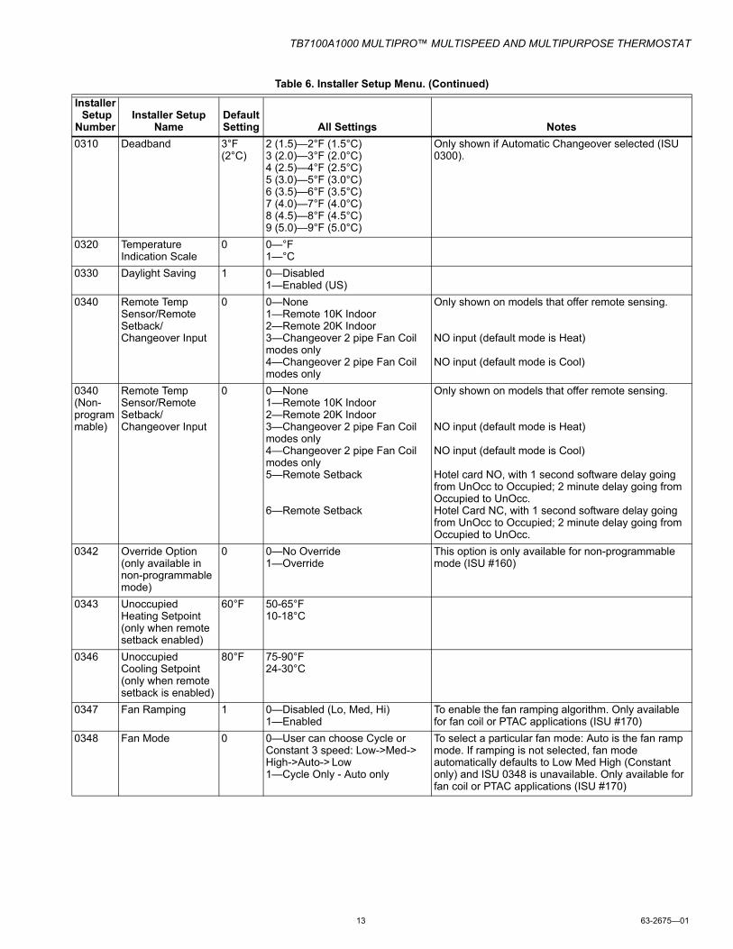
0342 Override Option (only available in non-programmable mode)
0 0—No Override1—Override
This option is only available for non-programmable mode (ISU #160)
0343 Unoccupied Heating Setpoint (only when remote setback enabled)
60°F 50-65°F10-18°C
0346 Unoccupied Cooling Setpoint (only when remote setback is enabled)
80°F 75-90°F24-30°C
0347 Fan Ramping 1 0—Disabled (Lo, Med, Hi)1—Enabled
To enable the fan ramping algorithm. Only available for fan coil or PTAC applications (ISU #170)
0348 Fan Mode 0 0—User can choose Cycle or Constant 3 speed: Low->Med->High->Auto-> Low 1—Cycle Only - Auto only
To select a particular fan mode: Auto is the fan ramp mode. If ramping is not selected, fan mode automatically defaults to Low Med High (Constant only) and ISU 0348 is unavailable. Only available for fan coil or PTAC applications (ISU #170)
Table 6. Installer Setup Menu. (Continued)
Installer Setup
NumberInstaller Setup
NameDefault Setting All Settings Notes
TB7100A1000 MULTIPRO™ MULTISPEED AND MULTIPURPOSE THERMOSTAT
63-2675—01 14
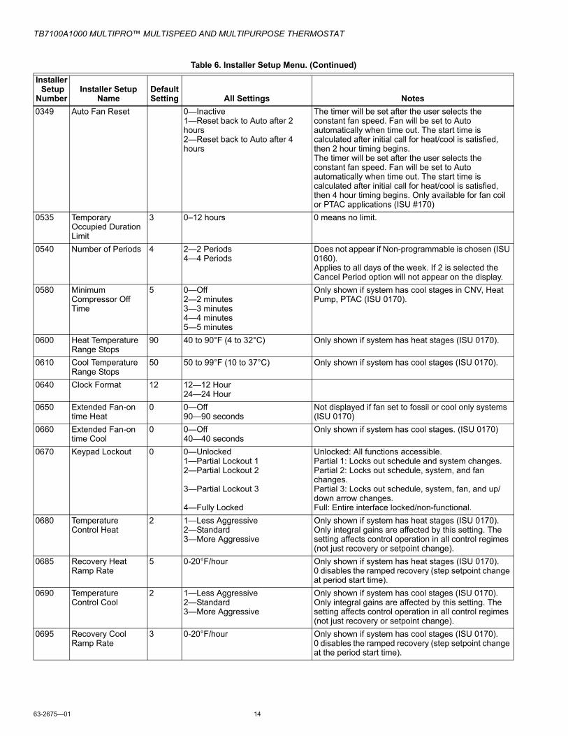
0349 Auto Fan Reset 0—Inactive 1—Reset back to Auto after 2 hours2—Reset back to Auto after 4 hours
The timer will be set after the user selects the constant fan speed. Fan will be set to Auto automatically when time out. The start time is calculated after initial call for heat/cool is satisfied, then 2 hour timing begins.The timer will be set after the user selects the constant fan speed. Fan will be set to Auto automatically when time out. The start time is calculated after initial call for heat/cool is satisfied, then 4 hour timing begins. Only available for fan coil or PTAC applications (ISU #170)
0535 Temporary Occupied Duration Limit
3 0–12 hours 0 means no limit.
0540 Number of Periods 4 2—2 Periods4—4 Periods
Does not appear if Non-programmable is chosen (ISU 0160).Applies to all days of the week. If 2 is selected the Cancel Period option will not appear on the display.
Unlocked: All functions accessible.Partial 1: Locks out schedule and system changes.Partial 2: Locks out schedule, system, and fan changes.Partial 3: Locks out schedule, system, fan, and up/down arrow changes.Full: Entire interface locked/non-functional.
0680 Temperature Control Heat
2 1—Less Aggressive2—Standard3—More Aggressive
Only shown if system has heat stages (ISU 0170).Only integral gains are affected by this setting. The setting affects control operation in all control regimes (not just recovery or setpoint change).
0685 Recovery Heat Ramp Rate
5 0-20°F/hour Only shown if system has heat stages (ISU 0170).0 disables the ramped recovery (step setpoint change at period start time).
0690 Temperature Control Cool
2 1—Less Aggressive2—Standard3—More Aggressive
Only shown if system has cool stages (ISU 0170).Only integral gains are affected by this setting. The setting affects control operation in all control regimes (not just recovery or setpoint change).
0695 Recovery Cool Ramp Rate
3 0-20°F/hour Only shown if system has cool stages (ISU 0170).0 disables the ramped recovery (step setpoint change at the period start time).
Table 6. Installer Setup Menu. (Continued)
Installer Setup
NumberInstaller Setup
NameDefault Setting All Settings Notes
TB7100A1000 MULTIPRO™ MULTISPEED AND MULTIPURPOSE THERMOSTAT
15 63-2675—01
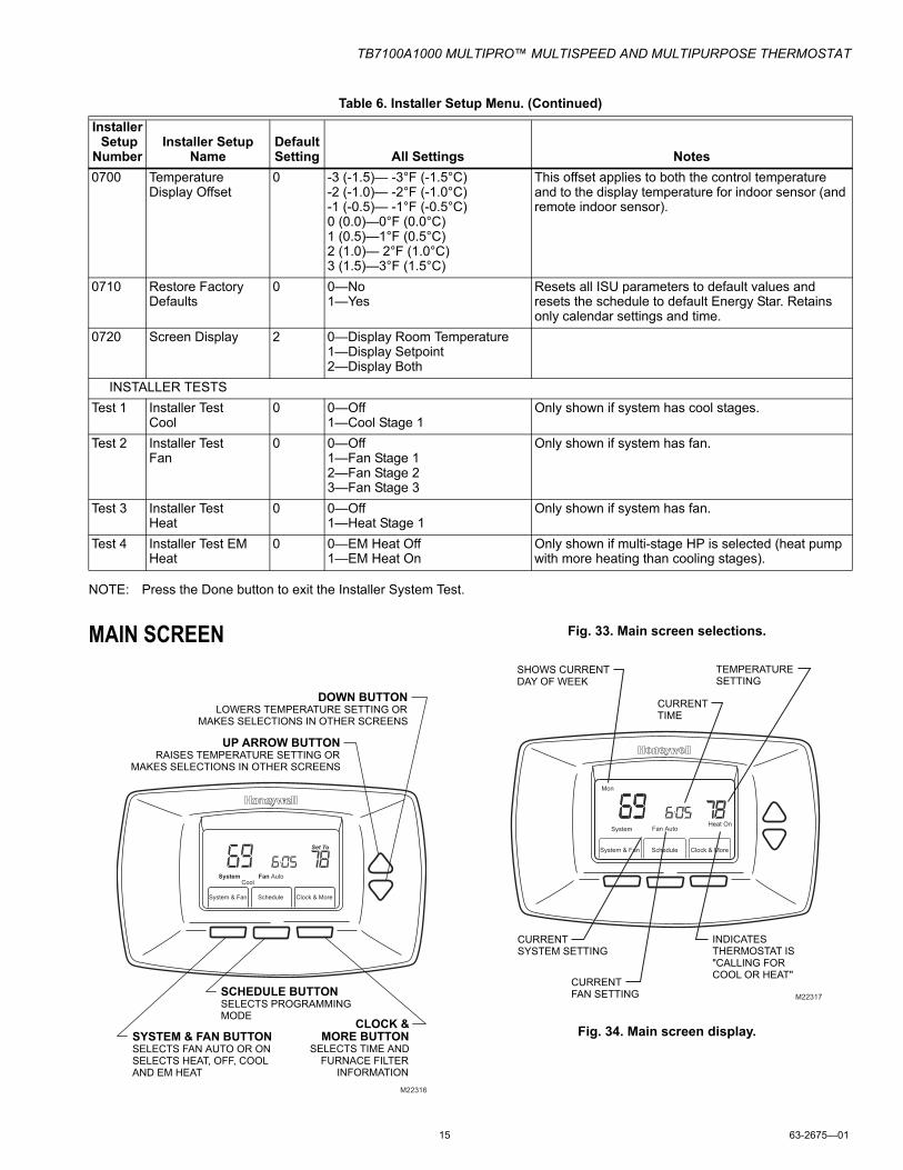
NOTE: Press the Done button to exit the Installer System Test.
This offset applies to both the control temperature and to the display temperature for indoor sensor (and remote indoor sensor).
0710 Restore Factory Defaults
0 0—No1—Yes
Resets all ISU parameters to default values and resets the schedule to default Energy Star. Retains only calendar settings and time.
0720 Screen Display 2 0—Display Room Temperature1—Display Setpoint2—Display Both
INSTALLER TESTSTest 1 Installer Test
Cool0 0—Off
1—Cool Stage 1Only shown if system has cool stages.
Test 2 Installer Test Fan
0 0—Off1—Fan Stage 12—Fan Stage 23—Fan Stage 3
Only shown if system has fan.
Test 3 Installer Test Heat
0 0—Off1—Heat Stage 1
Only shown if system has fan.
Test 4 Installer Test EM Heat
0 0—EM Heat Off1—EM Heat On
Only shown if multi-stage HP is selected (heat pump with more heating than cooling stages).
Table 6. Installer Setup Menu. (Continued)
Installer Setup
NumberInstaller Setup
NameDefault Setting All Settings Notes
M22316
UP ARROW BUTTON
RAISES TEMPERATURE SETTING ORMAKES SELECTIONS IN OTHER SCREENS
DOWN BUTTON
LOWERS TEMPERATURE SETTING ORMAKES SELECTIONS IN OTHER SCREENS
CLOCK &
MORE BUTTON
SELECTS TIME ANDFURNACE FILTER
INFORMATION
SYSTEM & FAN BUTTON
SELECTS FAN AUTO OR ONSELECTS HEAT, OFF, COOLAND EM HEAT
SCHEDULE BUTTON
SELECTS PROGRAMMING MODE
System
CoolFan Auto
System & Fan Schedule Clock & More
Set To
M22317
SHOWS CURRENTDAY OF WEEK
TEMPERATURESETTING
CURRENT TIME
CURRENTSYSTEM SETTING
CURRENT FAN SETTING
INDICATES THERMOSTAT IS "CALLING FOR COOL OR HEAT"
System & Fan Schedule Clock & More
Fan Auto
Mon
System AutoAux Heat On
TB7100A1000 MULTIPRO™ MULTISPEED AND MULTIPURPOSE THERMOSTAT
63-2675—01 16
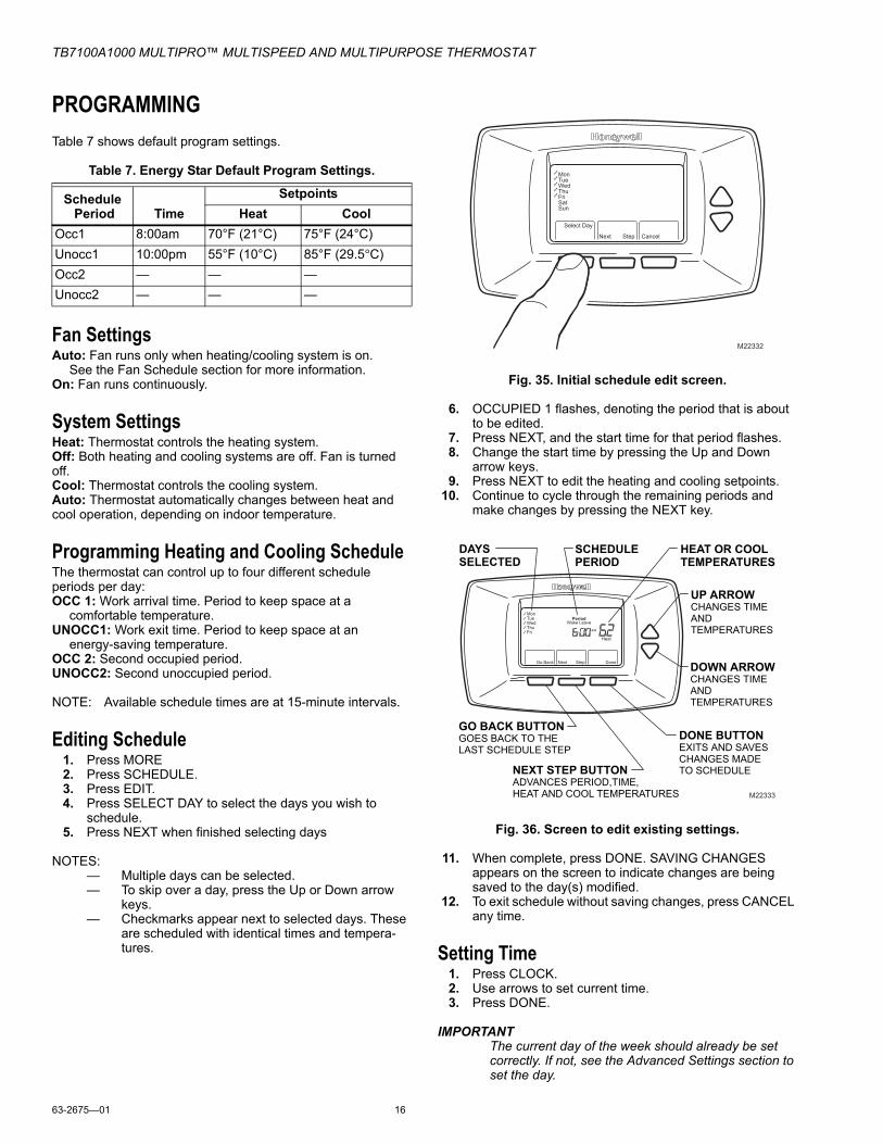
PROGRAMMINGTable 7 shows default program settings.
Table 7. Energy Star Default Program Settings.
Fan SettingsAuto: Fan runs only when heating/cooling system is on.
See the Fan Schedule section for more information.On: Fan runs continuously.
System SettingsHeat: Thermostat controls the heating system.Off: Both heating and cooling systems are off. Fan is turned off. Cool: Thermostat controls the cooling system.Auto: Thermostat automatically changes between heat and cool operation, depending on indoor temperature.
Programming Heating and Cooling ScheduleThe thermostat can control up to four different schedule periods per day:OCC 1: Work arrival time. Period to keep space at a
comfortable temperature.UNOCC1: Work exit time. Period to keep space at an
energy-saving temperature.OCC 2: Second occupied period.UNOCC2: Second unoccupied period.
NOTE: Available schedule times are at 15-minute intervals.
Editing Schedule1. Press MORE2. Press SCHEDULE.3. Press EDIT.4. Press SELECT DAY to select the days you wish to
schedule.5. Press NEXT when finished selecting days
NOTES:— Multiple days can be selected.— To skip over a day, press the Up or Down arrow
keys.— Checkmarks appear next to selected days. These
are scheduled with identical times and tempera-tures.
Fig. 35. Initial schedule edit screen.
6. OCCUPIED 1 flashes, denoting the period that is about to be edited.
7. Press NEXT, and the start time for that period flashes.8. Change the start time by pressing the Up and Down
arrow keys.9. Press NEXT to edit the heating and cooling setpoints.
10. Continue to cycle through the remaining periods and make changes by pressing the NEXT key.
Fig. 36. Screen to edit existing settings.
11. When complete, press DONE. SAVING CHANGES appears on the screen to indicate changes are being saved to the day(s) modified.
12. To exit schedule without saving changes, press CANCEL any time.
Setting Time1. Press CLOCK.2. Use arrows to set current time.3. Press DONE.
IMPORTANTThe current day of the week should already be set correctly. If not, see the Advanced Settings section to set the day.
TB7100A1000 MULTIPRO™ MULTISPEED AND MULTIPURPOSE THERMOSTAT
17 63-2675—01
OPERATION
Fan Sequence Operations (ISU 347, 348, 349)If heat pump or conventional application modes are enabled in ISU 170, then ISU 347 is not available for fan ramp algorithm. The fan operates as a default ON/AUTO selection that works the same way as our CommercialPRO TB7220 thermostat. There is only one fan relay output that is activated.
If PTAC or fan coil thermostat application modes are enabled in ISU 170, then ISU 347 fan ramp algorithm is available for installer setup selection. The fan ramp algorithm will automatically calculate the appropriate fan speed that is needed to meet the proportional band requirements to speed up setpoint satisfaction. When the setpoint is satisfied it will revert to the lowest fan speed setting to conserve energy.
The thermostat comes factory default with the fan ramping algorithm enabled (ISU 347). This gives the user the ability to select Auto-Lo-Med-Hi option in ISU 348 or Auto only option in ISU 348. Auto sets the thermostat into the fan ramping algorithm mode and automatically sets the sufficient speed for PI control. Auto also automatically shuts the fan off when there is not a call for heating or cooling. If the user decides to disable ISU 347, then the fan will only have Lo-Med-Hi option available.
If ISU 347 is not enabled, then ISU 348 does not appear as a user selection choice.
If ISU 347 is enabled, then ISU 349 is available as a selection choice. The user can select either a 2 hour or 4 hour timer fan reset function. The fan will reset from a constant on speed to Auto mode after the time period expires. If ISU 347 is not enabled, then ISU 349 does not appear as a user selection choice.
Equipment Sequence Operations (ISU 170)Heat Pump and ConventionalHeat Pump and conventional use a single fan speed. The single fan speed label is the G terminal relay output. Display on the thermostat for these modes will give the Fan On/Auto option. There is no fan ramping algorithm, ISU 347, 348, 349 are not available.
PTACPTAC modes 10 and 11 will have the same selection options available as the heat pump selection options. The only difference is that the PTAC options have a Lo and Hi speed fan output instead of single speed output and that it follows the fan sequencing described above with ISU 347, 348, 349.
4 Pipe4 pipe is treated similar to 1H/1C conventional. It follows the fan sequencing described above with ISU 347, 348, 349.
2 PipeThere are two different 2 pipe modes - 2 pipe only and 2 pipe with reheat.
2 pipe only - 2 pipe modes do not contain the ability to have automatic changeover. They are manual changeover only. The thermostat will have a priority when choosing a system mode (heat or cool). When ISU #340 has a 2 pipe changeover
sensor enabled, the thermostat screen system mode will lock on heat or cool (whatever the changeover sensor is communicating to the thermostat). If ISU #340 does not have a changeover sensor enabled, then the system mode from the thermostat screen can manually be adjusted between heat or cool. It follows the fan sequencing described above with ISU 347, 348, 349.
2 pipe with reheat - 2 pipe modes do not contain the ability to have automatic changeover. They are manual changeover only. The thermostat will have a priority when choosing a system mode (heat or cool). When ISU #340 has a 2 pipe changeover sensor enabled, the thermostat screen system mode will lock on heat only. When the 2 pipe changeover sensor is sensing cool mode, the user can adjust to heating mode which will bring on the auxiliary heat. If ISU #340 does not have a changeover sensor enabled, then the system mode from the thermostat screen can manually be adjusted between heat or cool. It follows the fan sequencing described above with ISU 347, 348, 349.
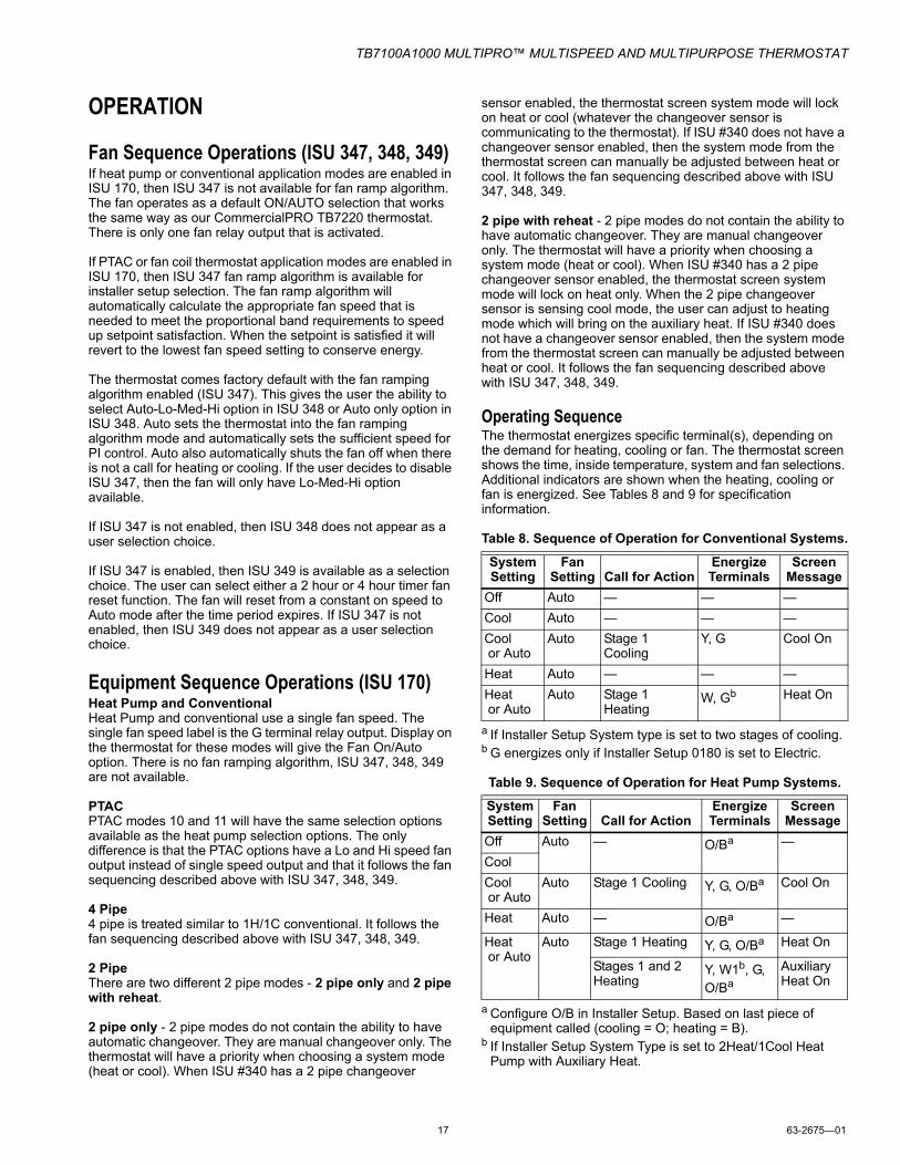
Operating SequenceThe thermostat energizes specific terminal(s), depending on the demand for heating, cooling or fan. The thermostat screen shows the time, inside temperature, system and fan selections. Additional indicators are shown when the heating, cooling or fan is energized. See Tables 8 and 9 for specification information.
Table 8. Sequence of Operation for Conventional Systems.
a If Installer Setup System type is set to two stages of cooling.b G energizes only if Installer Setup 0180 is set to Electric.
Table 9. Sequence of Operation for Heat Pump Systems.
a Configure O/B in Installer Setup. Based on last piece of equipment called (cooling = O; heating = B).
b If Installer Setup System Type is set to 2Heat/1Cool Heat Pump with Auxiliary Heat.
System Setting
Fan Setting Call for Action
Energize Terminals
Screen Message
Off Auto — — —Cool Auto — — —Cool or Auto
Auto Stage 1 Cooling
Y, G Cool On
Heat Auto — — —Heat or Auto
Auto Stage 1 Heating
W, Gb Heat On
System Setting
Fan Setting Call for Action
Energize Terminals
Screen Message
Off Auto — O/Ba —CoolCool or Auto
Auto Stage 1 Cooling Y, G, O/Ba Cool On
Heat Auto — O/Ba —
Heat or Auto
Auto Stage 1 Heating Y, G, O/Ba Heat On
Stages 1 and 2 Heating
Y, W1b, G, O/Ba
Auxiliary Heat On
TB7100A1000 MULTIPRO™ MULTISPEED AND MULTIPURPOSE THERMOSTAT
63-2675—01 18
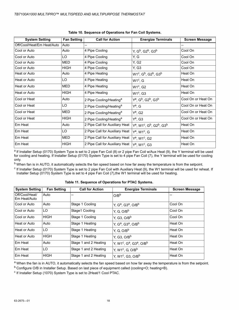
a If Installer Setup (0170) System Type is set to 2 pipe Fan Coil (8) or 2 pipe Fan Coil w/Aux Heat (9), the Y terminal will be usedfor cooling and heating. If Installer Setup (0170) System Type is set to 4 pipe Fan Coil (7), the Y terminal will be used for cooling only.b When fan is in AUTO, it automatically selects the fan speed based on how far away the temperature is from the setpoint.c If Installer Setup (0170) System Type is set to 2 pipe Fan Coil with Auxiliary Heat (9), the W1 terminal will be used for reheat. If
Installer Setup (0170) System Type is set to 4 pipe Fan Coil (7),the W1 terminal will be used for heating.
a When the fan is in AUTO, it automatically selects the fan speed based on how far away the temperature is from the setpoint. b Configure O/B in Installer Setup. Based on last piece of equipment called (cooling=O; heating=B).c If Installer Setup (1070) System Type is set to 2Heat/1 Cool PTAC.
Table 10. Sequence of Operations for Fan Coil Systems.
System Setting Fan Setting Call for Action Energize Terminals Screen MessageOff/Cool/Heat/Em Heat/Auto Auto -- --Cool or Auto Auto 4 Pipe Cooling Y, Gb, G2b, G3b Cool On
Cool or Auto LO 4 Pipe Cooling Y, G Cool OnCool or Auto MED 4 Pipe Cooling Y, G2 Cool OnCool or Auto HIGH 4 Pipe Cooling Y, G3 Cool OnHeat or Auto Auto 4 Pipe Heating W1c, Gb, G2b, G3b Heat On
Heat or Auto LO 4 Pipe Heating W1c, G Heat On
Heat or Auto MED 4 Pipe Heating W1c, G2 Heat On
Heat or Auto HIGH 4 Pipe Heating W1c, G3 Heat On
Cool or Heat Auto 2 Pipe Cooling/Heatinga Ya, Gb, G2b, G3b Cool On or Heat On
Cool or Heat LO 2 Pipe Cooling/Heatinga Ya, G Cool On or Heat On
Cool or Heat MED 2 Pipe Cooling/Heatinga Ya, G2 Cool On or Heat On
Cool or Heat HIGH 2 Pipe Cooling/Heatinga Ya, G3 Cool On or Heat On
Em Heat Auto 2 Pipe Call for Auxiliary Heat Ya, W1c, Gb, G2b, G3b Heat On
Em Heat LO 2 Pipe Call for Auxiliary Heat Ya, W1c, G Heat On
Em Heat MED 2 Pipe Call for Auxiliary Heat Ya, W1c, G2 Heat On
Em Heat HIGH 2 Pipe Call for Auxiliary Heat Ya, W1c, G3 Heat On
Table 11. Sequence of Operations for PTAC Systems.
System Setting Fan Setting Call for Action Energize Terminals Screen MessageOff/Cool/Heat/Em Heat/Auto
Auto -- O/Bb --
Cool or Auto Auto Stage 1 Cooling Y, Ga, G3a, O/Bb Cool On
Cool or Auto LO Stage1 Cooling Y, G, O/Bb Cool On
Cool or Auto HIGH Stage 1 Cooling Y, G3, O/Bb Cool On
Heat or Auto Auto Stage 1 Heating Y, Ga, G3a, O/Bb Heat On
Heat or Auto LO Stage 1 Heating Y, G, O/Bb Heat On
Heat or Auto HIGH Stage 1 Heating Y, G3, O/Bb Heat On
Em Heat Auto Stage 1 and 2 Heating Y, W1c, Ga, G3a, O/Bb Heat On
Em Heat LO Stage 1 and 2 Heating Y, W1c, G, O/Bb Heat On
Em Heat HIGH Stage 1 and 2 Heating Y, W1c, G3, O/Bb Heat On
TB7100A1000 MULTIPRO™ MULTISPEED AND MULTIPURPOSE THERMOSTAT
19 63-2675—01
Special Programmable Mode FunctionsInstaller Setup 160 allows the thermostat to be configured for either a mode with a programmable 7 day schedule or as a non-programmable thermostat.
Preoccupancy purge (ISU 185) This feature is available only when the thermostat is configured as a programmable schedule and when a fan is used. The fan will run 1-3 hours before the occupied schedule starting time to circulate air.
Override Button, Temporary Override (Duration Limit ISU 535)While in the programmable schedule mode, an override button is available to perform temporary override control. The default override time can be configured through ISU 535. Lockout configuration via ISU 670 can provide restrictions on access to setpoint changes, system changes, and schedule changes.
No remote setbackThe remote setback feature only works in the non-programmable mode.
Special Non-Programmable Mode FunctionsOverride (Optional)The override feature is optional in the non-programmable mode. The override can be configured through ISU 342. When the override is activated in the non-programmable mode it will temporarily override to a new setpoint until the end time expires.
Remote SetbackRemote Setback is available (ISU 340). Occupancy sensors, manual time clock inputs, and DDC night setback can be used to provide inputs to setback the thermostat. Unoccupied heating (ISU 343) and unoccupied cooling (ISU 346) setpoints are available to configure the setback setpoints.
Setting Temperature OverridesThere are three temperature override options:— Hold Temperature Until— Override, and — Holiday.
HOLD TEMPERATURE UNTILHolds the temperature temporarily until the time set by the user, or the next scheduled period time.
1. Press the Up or Down arrow next to the temperature to adjust. The Hold Until time appears on the screen. The time defaults to the next scheduled period start time
2. Press NEXT to adjust the time for the thermostat to resume schedule.
NOTE: The installer setup can limit the length of time for an override to 1, 2, 3, or 4 hours beyond the current time.
3. Press DONE or wait 5 seconds.4. Press CANCEL or SCHEDULE to cancel “Hold Tempera-
ture Until” and resume the schedule.
OVERRIDEChanges temperature setting until the next period takes effect. For use during Unoccupied periods.
1. Press OVERRIDE. The settings change by default to the next Occupied period.
NOTE: Changes are limited to those allowed by the lockout level.
2. Press Up or Down arrow to change the override temper-ature, and NEXT to adjust override time.
HOLIDAYChanges temperature setting for a designated number of days. Press MORE and then HOLIDAY. The screen shows “Hold Until 1 DAYS”.
1. Press Up or Down arrow to change the temperature desired for the thermostat to override the schedule.
2. Press NEXT to change the desired days for the duration of the holiday.
3. To cancel the Holiday Override early, press CANCEL.
Fan Status Displayed on Main ScreenWhen the thermostat is running the fan, the fan blade symbol
appears next to FAN to indicate the thermostat has the fan on.
NOTE: If the thermostat is not controlling the fan—typical for many gas, forced-air heating systems—the fan blade symbol will not appear even though the fan may be running.
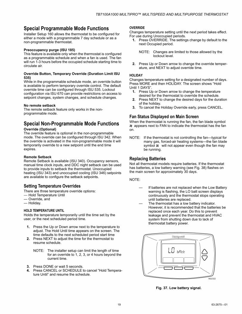
Replacing BatteriesNot all thermostat models require batteries. If the thermostat has batteries, a low battery warning (see Fig. 38) flashes on the main screen for approximately 30 days.
NOTE:
— If batteries are not replaced when the Low Battery warning is flashing, the LO batt screen displays continuously and the thermostat stops operating until batteries are replaced.
— The thermostat has a low battery indicator. However, it is recommended that the batteries be replaced once each year. Do this to prevent leakage and prevent the thermostat and HVAC system from shutting down due to lack of thermostat battery power.
Fig. 37. Low battery signal.
M22322
TB7100A1000 MULTIPRO™ MULTISPEED AND MULTIPURPOSE THERMOSTAT
63-2675—01 20
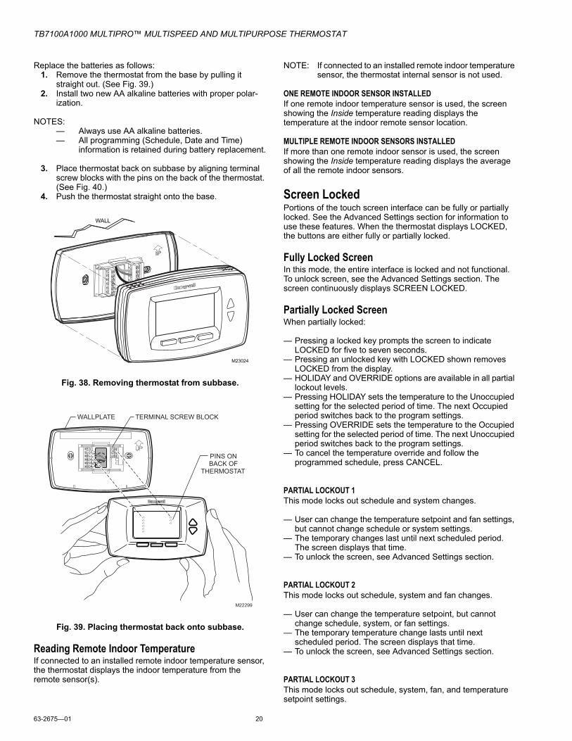
Replace the batteries as follows:1. Remove the thermostat from the base by pulling it
straight out. (See Fig. 39.)2. Install two new AA alkaline batteries with proper polar-
ization.
NOTES:— Always use AA alkaline batteries.— All programming (Schedule, Date and Time)
information is retained during battery replacement.
3. Place thermostat back on subbase by aligning terminal screw blocks with the pins on the back of the thermostat. (See Fig. 40.)
4. Push the thermostat straight onto the base.
Fig. 38. Removing thermostat from subbase.
Fig. 39. Placing thermostat back onto subbase.
Reading Remote Indoor TemperatureIf connected to an installed remote indoor temperature sensor, the thermostat displays the indoor temperature from the remote sensor(s).
NOTE: If connected to an installed remote indoor temperature sensor, the thermostat internal sensor is not used.
ONE REMOTE INDOOR SENSOR INSTALLEDIf one remote indoor temperature sensor is used, the screen showing the Inside temperature reading displays the temperature at the indoor remote sensor location.
MULTIPLE REMOTE INDOOR SENSORS INSTALLEDIf more than one remote indoor sensor is used, the screen showing the Inside temperature reading displays the average of all the remote indoor sensors.
Screen LockedPortions of the touch screen interface can be fully or partially locked. See the Advanced Settings section for information to use these features. When the thermostat displays LOCKED, the buttons are either fully or partially locked.
Fully Locked ScreenIn this mode, the entire interface is locked and not functional. To unlock screen, see the Advanced Settings section. The screen continuously displays SCREEN LOCKED.
Partially Locked ScreenWhen partially locked:
— Pressing a locked key prompts the screen to indicate LOCKED for five to seven seconds.
— Pressing an unlocked key with LOCKED shown removes LOCKED from the display.
— HOLIDAY and OVERRIDE options are available in all partial lockout levels.
— Pressing HOLIDAY sets the temperature to the Unoccupied setting for the selected period of time. The next Occupied period switches back to the program settings.
— Pressing OVERRIDE sets the temperature to the Occupied setting for the selected period of time. The next Unoccupied period switches back to the program settings.
— To cancel the temperature override and follow the programmed schedule, press CANCEL.
PARTIAL LOCKOUT 1This mode locks out schedule and system changes.
— User can change the temperature setpoint and fan settings, but cannot change schedule or system settings.
— The temporary changes last until next scheduled period. The screen displays that time.
— To unlock the screen, see Advanced Settings section.
PARTIAL LOCKOUT 2This mode locks out schedule, system and fan changes.
— User can change the temperature setpoint, but cannot change schedule, system, or fan settings.
— The temporary temperature change lasts until next scheduled period. The screen displays that time.
— To unlock the screen, see Advanced Settings section.
PARTIAL LOCKOUT 3This mode locks out schedule, system, fan, and temperature setpoint settings.
WALL
M23024
WALLPLATE
M22299
TERMINAL SCREW BLOCK
PINS ONBACK OF
THERMOSTAT
TB7100A1000 MULTIPRO™ MULTISPEED AND MULTIPURPOSE THERMOSTAT
21 63-2675—01
— Users cannot make changes to the temperature setpoint or any schedule, system, or fan settings.
— The only features available are HOLIDAY and OVERRIDE. — To unlock the screen, see Advanced Settings section.
Temperature RecoveryThe thermostat is equipped with a feature to eliminate guesswork when setting a schedule. That is, the user need not know the amount of time for the HVAC system to bring the space to temperature (without overshoot) prior to the scheduled time.The thermostat manages that automatically.
Simply set the program schedule to the desired time to have the space at comfort temperature. In addition, program the temperature to this comfort temperature. The thermostat activates the heating or cooling at the proper time to reach the scheduled temperature at the scheduled time.
NOTE: The setpoint changes gradually to use economical stages and avoid overshoot.
For example—the space will be occupied at 8:00 AM and the desired temperature is 70°F. Set the OCC 1 period for 8:00 AM and 70°F. The thermostat turns on the heat prior to 8:00 AM to raise the temperature to 70°F by 8:00 AM.
The thermostat provides an alert that the heating or cooling system is coming on before a scheduled time by displaying “Recovery” on the screen.
Minimum-Off Timer Compressor ProtectionThe thermostat has an adjustable Minimum-Off Timer that can be set from zero to five minutes (Factory Setting—five minutes). The Minimum-Off Timer can be bypassed through the Installer System Test or it can be bypassed permanently by setting the Minimum-Off Timer to 0 minutes in the Installer Setup. The Minimum-Off Timer is activated after the compressor turns off:— If the thermostat is system powered (common wire), the
Minimum-Off Timer is also activated upon initial startup and after power interruptions.
— If there is a call for cooling or heating during the Minimum-Off Time, the thermostat displays “Wait.”
— When the Minimum Off Timer expires, “Cool On” or “Heat On” (heat pumps only)” appears solidly in the display and the compressor and fan turn on.
Temperature Sensor Operation and CheckoutAllow outdoor or indoor temperature sensor to absorb the air for a minimum of five minutes before taking a reading. See the Sensor instructions for more information.
NOTE: The C7189U, TR21 and TR21-A Temperature Sensors are calibrated at the factory and cannot be recalibrated in the field.
C7189U Remote Indoor Temperature Sensor
OperationWhen installed with Thermostat ISU 0340 set to 3, the remote inside temperature is displayed on the Thermostat Home Screen as Inside Temperature. The thermostat internal temperature sensor is not used.
The C7189U can be used to provide one remote sensor input or as a temperature averaging network with multiple TR21 Sensors connected, as shown in Fig. 28.
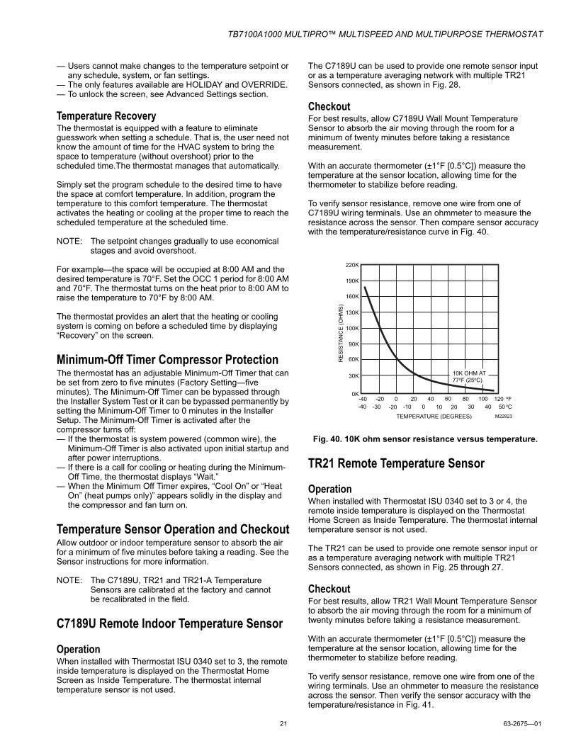
CheckoutFor best results, allow C7189U Wall Mount Temperature Sensor to absorb the air moving through the room for a minimum of twenty minutes before taking a resistance measurement.
With an accurate thermometer (±1°F [0.5°C]) measure the temperature at the sensor location, allowing time for the thermometer to stabilize before reading.
To verify sensor resistance, remove one wire from one of C7189U wiring terminals. Use an ohmmeter to measure the resistance across the sensor. Then compare sensor accuracy with the temperature/resistance curve in Fig. 40.
Fig. 40. 10K ohm sensor resistance versus temperature.
TR21 Remote Temperature Sensor
OperationWhen installed with Thermostat ISU 0340 set to 3 or 4, the remote inside temperature is displayed on the Thermostat Home Screen as Inside Temperature. The thermostat internal temperature sensor is not used.
The TR21 can be used to provide one remote sensor input or as a temperature averaging network with multiple TR21 Sensors connected, as shown in Fig. 25 through 27.
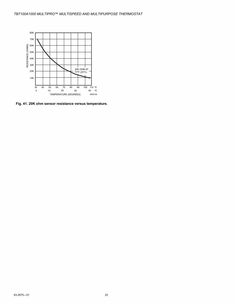
CheckoutFor best results, allow TR21 Wall Mount Temperature Sensor to absorb the air moving through the room for a minimum of twenty minutes before taking a resistance measurement.
With an accurate thermometer (±1°F [0.5°C]) measure the temperature at the sensor location, allowing time for the thermometer to stabilize before reading.
To verify sensor resistance, remove one wire from one of the wiring terminals. Use an ohmmeter to measure the resistance across the sensor. Then verify the sensor accuracy with the temperature/resistance in Fig. 41.
TEMPERATURE (DEGREES)
oF-40 -20 0 20 40 60 80 100 120-20-30-40 -10 40
RE
SIS
TAN
CE
(OH
MS
)
10K OHM AT 77oF (25oC)
220K
190K
160K
130K
100K
90K
60K
30K
oCM22823
0 10 20 30 50
0K
TB7100A1000 MULTIPRO™ MULTISPEED AND MULTIPURPOSE THERMOSTAT
63-2675—01 22
Fig. 41. 20K ohm sensor resistance versus temperature.
TEMPERATURE (DEGREES)
oF30 40 50 60 70 80 90 100 1100 10 20 30 40
RE
SIS
TAN
CE
(OH
MS
)
20K OHM AT 77oF (25oC)
80K
70K
60K
50K
40K
30K
20K
10K
oCM5874A
TB7100A1000 MULTIPRO™ MULTISPEED AND MULTIPURPOSE THERMOSTAT
Symptom Possible Cause ActionDisplay does not come on. Thermostat is not being powered. Check for 24 Vac between C and Rc.
Check that AAA batteries are installed correctly and are good.
Temperature settings do not change.
The upper or lower temperature limits were reached.
Check temperature setpoints.Check ISU 0600 and 0610; modify as needed.
The keypad is fully locked. Check ISU 0670 to change keypad locked options.
Heating or cooling does not come on.
Thermostat minimum off-time is activated. Wait up to five minutes for the system to respond.System selection is not set to Heat or Cool. Set system Selection to correct position.System type Selection is incorrect. Check ISU 0170 and make sure correct System
type is chosen.Thermostat is calling for Heat (Heat on) or Cool (Cool on) but no heating or cooling is running.
Heating or cooling equipment is not operating.
Check wiring.Check ISU 0170 and make sure correct system type is chosen.Verify operation of equipment in System Test mode.
Heat does not turn on (Heat On is solid in the display).
Heating equipment failure. Check for 24 Vac at the equipment on the secondary side of the transformer between power and common. If voltage is not present, check the heating equipment to find the cause of the problem.
Check for 24 Vac between the heat terminal (W) and transformer common. If 24 Vac is present, the thermostat is functional. Check the heating equipment to find the cause of the problem.
Loose or broken wire connection between thermostat and heating equipment.
Check for 24 Vac between the heat terminal (W) and transformer common. If voltage is not present, check wire connection (loose or broken) between the thermostat and the heating equipment.
Cooling does not turn on (Cool On is solid in the display).
Cooling equipment failure. Check for 24 Vac at the equipment on the secondary side of the transformer between power and common. If voltage is not present, check the cooling equipment to find the cause of the problem.
Check for 24 Vac between the cool terminal (Y) and transformer common. If 24 Vac is present, the thermostat is functional. Check the cooling equipment to find the cause of the problem.
Loose or broken wire connection between thermostat and cooling equipment.
Check for 24 Vac between the cool terminal (Y) and transformer common. If voltage is not present, check the wire connection (loose or broken) between the thermostat and the cooling equipment.
Fan does not turn on in a call for heat (electric furnace).
Fan Control in Heating is set to System Controls Fan (Setting 0180).
Set Fan Control in Heating to Thermostat Controls Fan (Setting 0180).
Heat pump puts out cool air in the heat mode and warm air in the cool mode.
Changeover Valve (ISU 0190) is not configured to match the changeover required by the installed heat pump.
Set Changeover Valve (ISU 0190) to match the changeover required by the installed heat pump.
Both the heating and cooling equipment are running at the same time.
The heating equipment is not a heat pump but the System Type (ISU 0170) is set to Heat Pump.
Set System Type (ISU 0170) to match the installed heating and/or cooling equipment.
Heating and cooling wires are shorted together.
Separate the shorted heating and cooling wires.
Automation and Control SolutionsHoneywell International Inc. Honeywell Limited-Honeywell Limitée1985 Douglas Drive North 35 Dynamic DriveGolden Valley, MN 55422 Toronto, Ontario M1V 4Z9customer.honeywell.com
TB7100A1000 MULTIPRO™ MULTISPEED AND MULTIPURPOSE THERMOSTAT
Perchlorate MaterialThis thermostat contains a Lithium battery which may contain Perchlorate material.
The following statement is required: Perchlorate Material—special handling may apply.See www.dtsc.ca.gov/hazardouswaste/perchlorate
Heating equipment is running in the cool mode.
Heating equipment is not a heat pump but System Type (ISU 0170) is set to Heat Pump.
Set System Type (ISU 0170) to match the installed heating and/or cooling equipment.
Heating equipment does not turn off and heat temperature setting is set below room temperature (Heat On is not in the display).
Heating equipment is not a heat pump but System Type (ISU 0170) is set to Heat Pump.
Set System Type (ISU 0170) to match the installed heating and/or cooling equipment.
Cannot set the system setting to Heat.
System Type (ISU 0170) is set to Cool Only.
Set System Type (ISU 0170) to match the installed heating and/or cooling equipment.
Cannot set the system setting to Cool.
System Type (ISU 0170) is set to Heat Only or Heat Only with Fan.
Set System Type (ISU 0170) to match the installed heating and/or cooling equipment.
Heat On is not in the display. System setting is not set to Heat and/or temperature setting is not set above room temperature.
Set the system setting to Heat and set the temperature setting above the room temperature.
Cool On is not in the display. System setting is not set to Cool and/or the temperature setting is not set below room temperature.
Set the system setting to Cool and set the temperature setting below the room temperature.
Wait is in the display. Compressor minimum off timer is active. Wait up to five minutes for the cooling or heating (heat pump) equipment to turn on.
“Screen Locked” appears on the screen and all or some of the keys do not respond.
The keypad is fully or partially locked. Check ISU 0670 to change keypad locked options.
Table 12. Troubleshooting. (Continued)
Symptom Possible Cause Action
By using this Honeywell literature, you agree that Honeywell will have no liability for any damages arising out of your use or modification to, the literature. You will defend and indemnify Honeywell, its affiliates and subsidiaries, from and against any liability, cost, or damages, including attorneys’ fees, arising out of, or resulting from, any modification to the literature by you.