643 Related Information FIBER SENSORS LASER SENSORS PHOTOELECTRIC SENSORS MICRO PHOTOELECTRIC SENSORS AREA SENSORS LIGHT CURTAINS / SAFETY COMPONENTS PRESSURE / FLOW SENSORS INDUCTIVE PROXIMITY SENSORS PARTICULAR USE SENSORS SENSOR OPTIONS SIMPLE WIRE-SAVING UNITS WIRE-SAVING SYSTEMS MEASUREMENT SENSORS STATIC ELECTRICITY PREVENTION DEVICES LASER MARKERS PLC HUMAN MACHINE INTERFACES ENERGY CONSUMPTION VISUALIZATION COMPONENTS FA COMPONENTS MACHINE VISION SYSTEMS UV CURING SYSTEMS Selection Guide Light Curtains Safety Components Optical Touch Switch Control Units Definition of Sensing Heights SG-B1/SG-A1 SG-B2 SG-C1 SG-D1 SG-E1 SD3-A1 ST4 Ultra-slim safety door switch Conforming to Machine & EMC Directives Certified Safety Door Switch with Solenoid Interlock / Safety Door Switch Ultra-slim ■ General terms and conditions ............. F-7 ■ General precautions ..................... P.1501 SG-B1 SERIES / SG-A1 SERIES Introducing a safety door switch with solenoid interlock that is among the world’s thinnest*! With 5 built-in contacts Manual lock release can be operated from three directions. Space saving design with angled connection cable SG-B1 series Minimum radius 30 mm 1.181 in Minimum radius 30 mm 1.181 in Space saving approx. 30 mm 1.181 in Angled connection cable *Based on research conducted by our company as of March 2013. 75 mm 2.953 in 75 mm 2.953 in 15 mm 0.591 in Thin body panasonic.net/id/pidsx/global
Transcript
643
Related InformationFIBERSENSORS
LASERSENSORS
PHOTOELECTRICSENSORS
MICROPHOTOELECTRIC
SENSORS
AREASENSORS
LIGHT CURTAINS /SAFETY
COMPONENTSPRESSURE /
FLOWSENSORS
INDUCTIVEPROXIMITY
SENSORS
PARTICULARUSE SENSORS
SENSOROPTIONS
SIMPLEWIRE-SAVING
UNITS
WIRE-SAVING SYSTEMS
MEASUREMENTSENSORS
STATIC ELECTRICITYPREVENTION
DEVICES
LASERMARKERS
PLC
HUMAN MACHINE INTERFACES
ENERGY CONSUMPTION VISUALIZATION COMPONENTS
FA COMPONENTS
MACHINE VISION SYSTEMS
UV CURING SYSTEMS
Selection Guide
Light Curtains
Safety Components
Optical Touch Switch
Control Units
Definition of Sensing Heights
SG-B1/SG-A1 SG-B2
SG-C1
SG-D1
SG-E1
SD3-A1
ST4
Ultra-slim safety door switch
Conforming to Machine& EMC Directives
Certified
Safety Door Switch with Solenoid Interlock / Safety Door Switch Ultra-slim
■General terms and conditions ............. F-7 ■General precautions ..................... P.1501
SG-B1 SERIES / SG-A1 SERIES
Introducing a safety door switch with solenoid interlock that is among the world’s thinnest*! With 5 built-in contacts
Manual lock release can be operated from three directions.
Space saving design with angled connection cable
SG-B1 series
Min
imum
radi
us
30 m
m 1
.181
in
Min
imum
radi
us
30 m
m 1
.181
in
Space saving approx. 30 mm 1.181 in
Angledconnection
cable
* Based on research conducted by our company as of March 2013.
75 mm 2.953 in
75 mm 2.953 in
15 mm 0.591 in
Thinbody
panasonic.net/id/pidsx/global
Safety Door Switch with Solenoid Interlock / Safety Door Switch SG-B1 SERIES / SG-A1 SERIES 644
Choose between two types of locks:• Spring lock• Magnet lock
Easy-to-see LED operation indicator
Features three built-in contacts yet is among world’s smallest designs.
Choose from two actuator entry slot orientations.
Top mounting
Top mounting
Side mounting
Top mounting
Side mounting
Bottom mounting
Front mountingFront mounting
Mounting surface
The indicator is visible even from an angle.
Wide viewing angle (approx. 120°)
Actuator
SG-B1series
Right-opening
Right-opening
Left-opening
Left-opening
Left-opening
Right-opening
Left-opening
Right-opening
Up-opening Up-opening
Can be installed on any door.
645 Safety Door Switch with Solenoid Interlock / Safety Door Switch SG-B1 SERIES / SG-A1 SERIES
FIBERSENSORS
LASERSENSORS
PHOTOELECTRICSENSORS
MICROPHOTOELECTRIC
SENSORS
AREASENSORS
LIGHT CURTAINS /SAFETY
COMPONENTSPRESSURE /
FLOWSENSORS
INDUCTIVEPROXIMITY
SENSORS
PARTICULARUSE SENSORS
SENSOROPTIONS
SIMPLEWIRE-SAVING
UNITS
WIRE-SAVING SYSTEMS
MEASUREMENTSENSORS
STATIC ELECTRICITYPREVENTION
DEVICES
LASERMARKERS
PLC
HUMAN MACHINE INTERFACES
ENERGY CONSUMPTION VISUALIZATION COMPONENTS
FA COMPONENTS
MACHINE VISION SYSTEMS
UV CURING SYSTEMS
Selection Guide
Light Curtains
Safety Components
Optical Touch Switch
Control Units
Definition of Sensing Heights
SG-B1/SG-A1 SG-B2
SG-C1
SG-D1
SG-E1
SD3-A1
ST4
All models come with cables pre-installed.The SG-B1 series and SG-A1 series ship with bundled cables already connected internally.Since there is no need to provide cables separately, and because they are already connected internally, the number of wiring man-hours is cut in half.
Energy-saving designThe SG-B1 series features an energy-saving design requiring current consumption of just 110 mA at 24 V DC (100 mA for the solenoid and 10 mA for the indicator), even though it also incorporates a solenoid interlock.
SG-B1 series / SG-A1 series Standard door switch
Ships standard with cables. Cable
Integrated design
Low power consumption of 110 mA
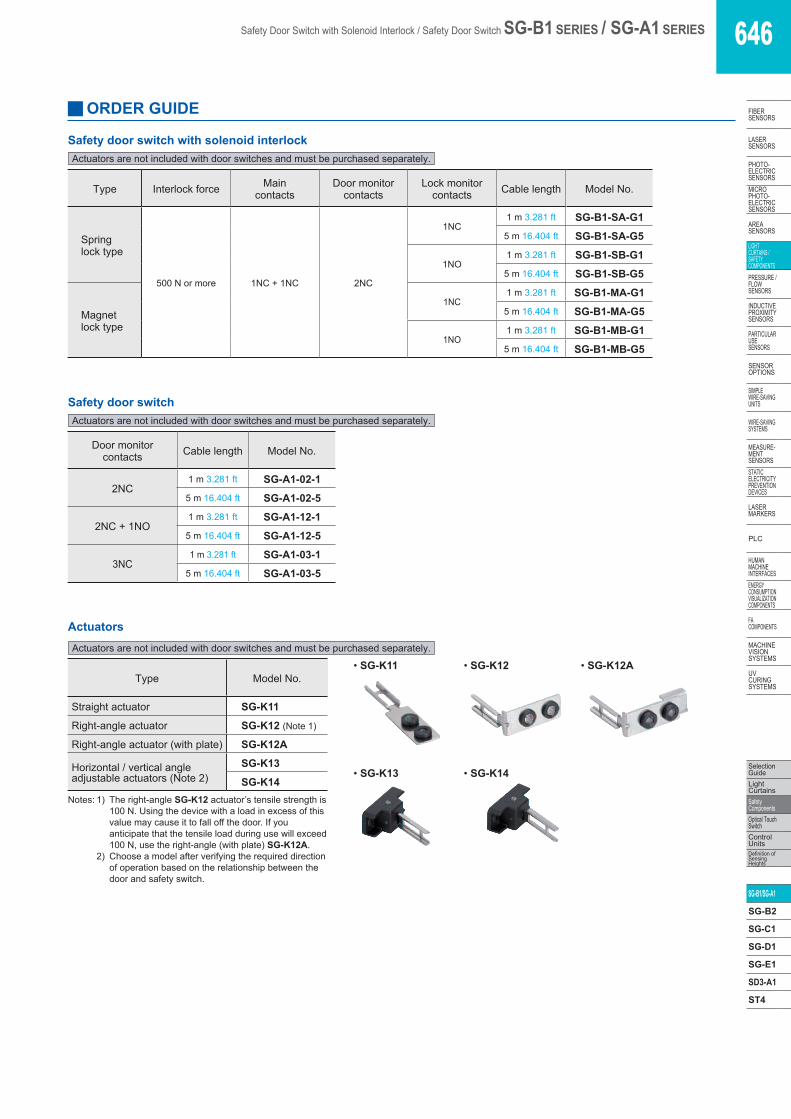
Safety Door Switch with Solenoid Interlock / Safety Door Switch SG-B1 SERIES / SG-A1 SERIES 646
SG-K14Notes: 1) The right-angle SG-K12 actuator’s tensile strength is
100 N. Using the device with a load in excess of this value may cause it to fall off the door. If you anticipate that the tensile load during use will exceed 100 N, use the right-angle (with plate) SG-K12A.
2) Choose a model after verifying the required direction of operation based on the relationship between the door and safety switch.
Actuators are not included with door switches and must be purchased separately.
647 Safety Door Switch with Solenoid Interlock / Safety Door Switch SG-B1 SERIES / SG-A1 SERIES
FIBERSENSORS
LASERSENSORS
PHOTO-ELECTRICSENSORS
MICROPHOTO-
ELECTRICSENSORS
AREASENSORS
LIGHTCURTAINS /
SAFETYCOMPONENTS
PRESSURE / FLOW
SENSORS
INDUCTIVEPROXIMITY
SENSORS
PARTICULARUSE
SENSORS
SENSOROPTIONS
SIMPLEWIRE-SAVING
UNITS
WIRE-SAVING SYSTEMS
MEASURE-MENT
SENSORSSTATIC
ELECTRICITYPREVENTION
DEVICES
LASERMARKERS
PLC
HUMAN MACHINE
INTERFACESENERGY
CONSUMPTION VISUALIZATION COMPONENTS
FA COMPONENTS
MACHINE VISION
SYSTEMS
UV CURING
SYSTEMS
Selection GuideLight
CurtainsSafety
ComponentsOptical Touch
SwitchControl
UnitsDefinition of
Sensing Heights
SG-B1/SG-A1 SG-B2
SG-C1
SG-D1
SG-E1
SD3-A1
ST4
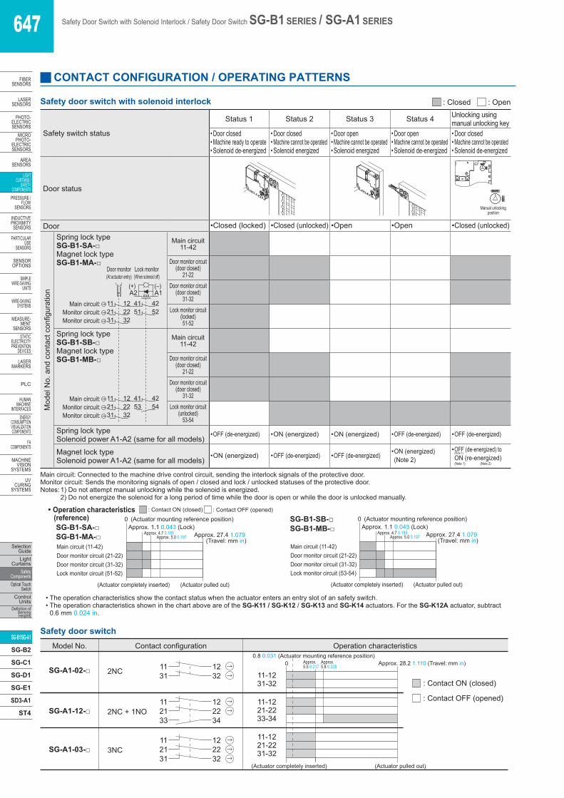
CONTACT CONFIGURATION / OPERATING PATTERNS
Safety switch status
Status 1 Status 2 Status 3 Status 4 Unlocking using manual unlocking key
• Door closed• Machine ready to operate• Solenoid de-energized
• Door closed• Machine cannot be operated• Solenoid energized
• Door open• Machine cannot be operated• Solenoid energized
• Door open• Machine cannot be operated• Solenoid de-energized
• Door closed• Machine cannot be operated• Solenoid de-energized
Door status
Manual unlockingposition
Door • Closed (locked) • Closed (unlocked) • Open • Open • Closed (unlocked)
Mod
el N
o. a
nd c
onta
ct c
onfig
urat
ion
Spring lock type SG-B1-SA-□Magnet lock typeSG-B1-MA-□
Main circuit11-42
Door monitor circuit(door closed)
21-22Door monitor circuit
(door closed)31-32
Lock monitor circuit(locked)51-52
Spring lock typeSG-B1-SB-□Magnet lock typeSG-B1-MB-□
Main circuit11-42
Door monitor circuit(door closed)
21-22Door monitor circuit
(door closed)31-32
Lock monitor circuit(unlocked)
53-54Spring lock typeSolenoid power A1-A2 (same for all models)
• OFF (de-energized) • ON (energized) • ON (energized) • OFF (de-energized) • OFF (de-energized)
Magnet lock typeSolenoid power A1-A2 (same for all models)
• ON (energized) • OFF (de-energized) • OFF (de-energized) • ON (energized) (Note 2)
• OFF (de-energized) toO(Note 1)
N (re-energized)(Note 1) (Note 2)
Main circuit: Connected to the machine drive control circuit, sending the interlock signals of the protective door.Monitor circuit: Sends the monitoring signals of open / closed and lock / unlocked statuses of the protective door.Notes: 1) Do not attempt manual unlocking while the solenoid is energized. 2) Do not energize the solenoid for a long period of time while the door is open or while the door is unlocked manually.
• The operation characteristics show the contact status when the actuator enters an entry slot of an safety switch.• The operation characteristics shown in the chart above are of the SG-K11 / SG-K12 / SG-K13 and SG-K14 actuators. For the SG-K12A actuator, subtract
0.6 mm 0.024 in.
Monitor circuit:Monitor circuit:
Monitor circuit:Monitor circuit:
A1A2(+) (–)
41 421211
41 421211
21 22
51 52
Main circuit:
Main circuit:
31 3253 54
32312221
Door monitor(At actuator entry)
Lock monitor(When solenoid off)
Monitor circuit:Monitor circuit:
Monitor circuit:Monitor circuit:
A1A2(+) (–)
41 421211
41 421211
21 22
51 52
Main circuit:
Main circuit:
31 3253 54
32312221
Door monitor(At actuator entry)
Lock monitor(When solenoid off)
Safety Door Switch with Solenoid Interlock / Safety Door Switch SG-B1 SERIES / SG-A1 SERIES 648
Ambient temperature:-25 to +35 °C -13 to +95 °F2.5 A (up to 2 circuits) 1.0 A (3 or more circuits)
Ambient temperature35 to +50 °C 95 to +122 °F1.0 A (1 circuit)0.5 A (2 or more circuits)
Rated operational voltage (Ue) / Rated operational current (Ie)
Ie Ue 30 V 125 V 250 V
Main circuit, look monitor
circuit
AC Resistive load (AC-12) - 2 A -
Inductive load (AC-15) - 1 A -
DC Resistive load (DC-12) 2 A 0.4 A -
Inductive load (DC-13) 1 A 0.22 A -
Door monitor circuit
AC Resistive load (AC-12) - 2.5 A 1.5 A
Inductive load (AC-15) - 1.5 A 0.75 A
DC Resistive load (DC-12) 2.5 A 1.1 A 0.55 A
Inductive load (DC-13) 2.3 A 0.55 A 0.27 AElectric shock protection class Class II (IEC 61140) (Note 1), (double insulated)Operating frequency 900 operations/hourActuator operating speed 0.05 to 1.0 m/sec.B10d 2,000,000 (ISO 13849-1 Annex C Table C.1)Mechanical durability 1,000,000 operations min. (GS-ET-19)
Electrical durability
100,000 operations min. 900 operations/hour, AC-12 125 V 2A, DC-12 125 V 0.4 A
1,000,000 operations min.900 operations/hour, 24 V AC/DC 0.1 A resistive load
Interlock force 500 N min. (GS-ET-19) (Note 2)Direct opening travel 8 mm 0.315 in min.Direct opening force 60 N min.Contact resis-tance
300 mΩ max. (initial value, 1 m 3.281 ft cable)700 mΩ max. (initial value, 5 m 16.404 ft cable)
Malfunction: 10 to 55 Hz, half amplitude 0.35 mm 0.014 inDestruction: 30 Hz, half amplitude 1.5 mm 0.059 in
Short-circuit protective device Use 250 V / 10 A fast acting type fuseMaterial Enclosure: PA66 Cable UL style 2464, No.22 AWG 12-core
Solen
oid / I
ndica
tor Rated operating voltage DC 24 V 100% duty cycleRated current 110 mA (solenoid 100 mA, LED 10 mA : initial value)Turn on voltage Rated voltage × 85 % max. (at 20 °C 68 °F)Turn off voltage Rated voltage × 10 % min. (at 20 °C 68 °F)Indicator Green LED
Weight SG-B1-□-G1: Approx. 220 g, SG-B1-□-G5: Approx. 600 g
Designation Safety door switchItem Series SG-A1 seriesApplicable standards
EN 1088, IEC 60947-5-1, EN 60947-5-1,GS-ET-15, UL 508, CSA C22.2 No.14
Standards for use IEC 60204-1, EN 60204-1Applicable directives
Machinery directive (2006/42/EC)Low voltage directive (2006/95/EC)
Opera
ting c
ondit
ion Ambient temperature
-25 to +70 °C -13 to +158 °F (No dew condensation or icing allowed)Storage: -40 to +80 °C -40 to +176 °F
Rated operational voltage (Ue) /Rated operational current (Ie)
Ie Ue 30 V 125 V 250 V
ACResistive load (AC-12) - 2.5 A 1.5 AInductive load (AC-15) - 1.5 A 0.75 A
DCResistive load (DC-12) 2.5 A 1.1 A 0.55 AInductive load (DC-13) 2.3 A 0.55 A 0.27 A
Electric shock protection class
Class II (IEC 61140), (double insulated)
Protection IP67 (IEC 60529)
Shock resistance Malfunction: 300 m/s2
Destruction: 1,000 m/s2
Vibration resistance
Malfunction: 5 to 55 Hz, half amplitude 0.5 mm 0.020 inDestruction: 30 Hz, half amplitude 1.5 mm 0.059 in
Operating frequency 1,200 operations/hour
Actuator operating speed 0.05 to 1.0 m/sec.
B10d 2,000,000 (ISO 13849-1 Annex C Table C.1)Mechanical durability 1,000,000 operations min. (GS-ET-15)
Electrical durability
100,000 operations min. (AC-12, 250 V 1.5 A, DC-12 250 V 0.2 A)
1,000,000 operations min. (AC/DC 24 V 100 mA)(1,200 operations/hour)
Direct opening travel 8 mm 0.315 in min.Direct opening force 60 N min.Contact resistance
300 mΩ max. (initial value, 1 m 3.281 ft cable)700 mΩ max. (initial value, 5 m 16.404 ft cable)
Short-circuit protective device Use 250 V / 10 A fast acting type fuse
Conditional short-circuit current 50 A (250 V)
Material Enclosure: PA66Cable UL style 2464, No.20 AWG 6-coreWeight SG-A1-□-1: Approx. 120 g, SG-A1-□-5: Approx. 420 g
Notes: 1) Basic insulation of 2.5 kV, 1.5 kV impulse withstand voltage is ensured between different contact circuits and between contact circuits and LED or solenoid in the enclosure. When both SELV (safety extra low voltage) or PELV (protective extra low voltage) circuits and other circuits (such as 230 V AC circuits) are used for the solenoid power and contact circuits at the same time, the SELV or PELV requirements are not met any more.
2) The actuator locking strength is rated at 500 N of static load. Do not apply a load higher than the rated value.
Do not apply a load higher than the rated value. When a higher load is expected to work on the actuator, provide an additional
system consisting of another safety switch without lock (such as the SG-A1 safety switch) or a sensor to detect door opening and stop the machine.
649 Safety Door Switch with Solenoid Interlock / Safety Door Switch SG-B1 SERIES / SG-A1 SERIES
FIBERSENSORS
LASERSENSORS
PHOTO-ELECTRICSENSORS
MICROPHOTO-
ELECTRICSENSORS
AREASENSORS
LIGHTCURTAINS /
SAFETYCOMPONENTS
PRESSURE / FLOW
SENSORS
INDUCTIVEPROXIMITY
SENSORS
PARTICULARUSE
SENSORS
SENSOROPTIONS
SIMPLEWIRE-SAVING
UNITS
WIRE-SAVING SYSTEMS
MEASURE-MENT
SENSORSSTATIC
ELECTRICITYPREVENTION
DEVICES
LASERMARKERS
PLC
HUMAN MACHINE
INTERFACESENERGY
CONSUMPTION VISUALIZATION COMPONENTS
FA COMPONENTS
MACHINE VISION
SYSTEMS
UV CURING
SYSTEMS
Selection GuideLight
CurtainsSafety
ComponentsOptical Touch
SwitchControl
UnitsDefinition of
Sensing Heights
SG-B1/SG-A1 SG-B2
SG-C1
SG-D1
SG-E1
SD3-A1
ST4
• Although the SG-K11 / SG-K12 / SG-K12A actuators alleviate shock when the actuator enters a slot in the safety switch, make sure that excessive shock is not applied. If the rubber bushings become deformed or cracked, replace with new ones.
SG-A1 series• Cover the unused actuator entry slot using the slot plug supplied
with the safety switch.
Minimum radius of hinged door• When using the safety switch on hinged doors, refer to the mini-
mum radius of doors shown below. When using on doors with small minimum radius, use the angle adjustable actuator (SG-K13 / SG-K14).
Note: The values indicated in the figures below assume that there is no mechanical interference between the actuator and the safety switch when the door is opened or closed. Because deviation or dislocation of hinged doors may occur in actual applications, make sure of the correct operation before installation.
When using the right-angle actuator (SG-K12 / SG-K12A)
SG-B1 series<When the door hinge is on the extension line of the actuator mounting surface>
<When the door hinge is on the extension line of the safety switch surface>
SG-A1 series<When the door hinge is on the extension line of the actuator mounting surface>
Door hinge
Door hinge
Door hinge
Door hinge
SG-K12
SG-K12
230 mm 9.055 in
Minimum radius
230 mm 9.055 in
Minimum radius
160 mm 6.299 in
Minimum radius160 mm 6.299 in
Minimum radius
<When the door hinge is on the extension line of the safety switch surface>
Door hinge
Door hinge
Door hinge
Door hinge
SG-K12
SG-K12
230 mm 9.055 in
Minimum radius
230 mm 9.055 in
Minimum radius
160 mm 6.299 in
Minimum radius160 mm 6.299 in
Minimum radius
• This catalog is a guide to select a suitable product. Be sure to read the instruction manual attached to the product prior to its use.
• In order to avoid electric shock or fire, turn the power off before installation, removal, wire connection, maintenance, or inspection of the safety switch.
• If relays are used in the circuit between the safety switch and the load, consider the danger and use safety relays, since welding or sticking contacts of standard relays may invalidate the functions of the safety switch.
• Do not place a PLC in the circuit between the safety switch and the load. Safety and security can be endangered in the event of a malfunction of the PLC.
• Do not disassemble or modify the safety switch, otherwise a breakdown or an accident may occur.
• Do not install the actuator in a location where the human body may come in contact. Otherwise injury may occur.
• Magnet lock type is locked when energized, and unlocked when de-energized. When energization is interrupted due to wire disconnection or other failures, the safety switch may be unlocked causing possible danger to the operators. Magnet lock type must not be used in applications where locking is strictly required for safety. Perform a risk assessment and determine whether solenoid lock type is appropriate.
Both series• Regardless of door types, do not use the safety switch as a door
stop. Install a mechanical door stop at the end of the door to protect the safety switch against excessive force.
• Do not apply external force on the actuator while unlocking, other-wise the actuator may not be unlocked.
• Do not apply excessive shock to the safety switch when opening or closing the door. A shock to the safety switch exceeding 1,000 m/s2 may cause damage to the safety switch.
• If the operating atmosphere is contaminated, use a protective cover to prevent the entry of foreign objects into the safety switch through the actuator entry slots. Entry of a considerable amount of foreign objects into the safety switch may affect the mechanism of the safety switch and cause a malfunction.
• Do not store the safety switches in a dusty, humid, or organic-gas atmosphere, or in an area subjected to direct sunlight.
• Use proprietary actuators only. When other actuators are used, the safety switch may be damaged.
SG-B1 series• The locking strength is rated at 500 N. Do not apply a load higher
than the rated value. When a higher load is expected, provide an additional system consisting of another safety switch without lock (such as the SG-A1 safety switch) or a sensor to detect door opening and stop the machine.
• Regardless of door types, do not use the safety switch as a door lock. Install a separate lock using a latch or other measures.
• While the solenoid is energized, the switch temperature rises ap-proximately 35 °C 95 °F above the ambient temperature (to ap-proximately 85 °C 185 °F while the ambient temperature is 50 °C 122 °F). Do not touch to prevent burns. If cables come into contact with the switch, use heat-resistant cables.
• Bouncing will occur on the lock monitor contact during locking and unlocking (reference value: 20 ms).
PRECAUTIONS FOR PROPER USE Refer to p.1501 for general precautions.
Safety Door Switch with Solenoid Interlock / Safety Door Switch SG-B1 SERIES / SG-A1 SERIES 650
HUMAN MACHINE INTERFACESENERGY CONSUMPTION VISUALIZATION COMPONENTS
FA COMPONENTS
MACHINE VISION SYSTEMS
UV CURING SYSTEMS
Selection GuideLight CurtainsSafety ComponentsOptical Touch SwitchControl UnitsDefinition of Sensing Heights
SG-B1/SG-A1
SG-B2
SG-C1
SG-D1
SG-E1
SD3-A1
ST4
PRECAUTIONS FOR PROPER USE
Mounting• Mount the safety switch on a fixed piece of machinery or guard
and the actuator on a hinged door. Avoid mounting both the safety switch and actuator on a hinged door. Doing so may cause equipment failure. For more information about how to mount the devices, see the following diagram:
SG-K12AActuator
(Application on hinged doors)
Latch
(Application on sliding doors)Door stop
SG-B1 series Safety switch
Door
SG-K11Actuator
Note: When mounting the actuator, make sure that the actuator enters the slot in the correct direction, as shown on the right figure.
Recommended tightening torque for mounting screwsSafety switch: 1.0 to 1.5 N·m (Three M4 screws)*Actuator: 1.0 to 1.5 N·m (Two M4 screws)** The above recommended tightening torques of the mounting screws are the values confirmed with hexagon-socket-head bolts. When other screws are used and tightened to a smaller torque, make sure that the screws do not become loose after mounting.
• Mounting bolts must be provided by the users.• To avoid unauthorized or unintended removal of the safety switch
and the actuator, it is recommended that the safety switch and ac-tuator are installed in a secure manner, for example using special screws or welding the screws.
• When installing the SG-K12A actuator, use the mounting plate (supplied with the actuator) on the hinged door, and mount tightly using two M4 screws.The mounting plate has orientation.Do not lose the mounting plate. Adequate performance cannot be obtained without the plate as the actuator may fall off the door.
Cables• Do not fasten or loosen the gland at the bottom of the safety switch.• When bending the cable during wiring, make sure that the cable
radius is kept at 30 mm 1.181 in minimum.• When wiring, make sure that water or oil does not enter the cable.• The solenoid has polarity. Make sure of the correct polarity when
wiring.
SG-B1 series
SG-A1 series
Minimum
radiu
s
40 m
m 1.57
5 in
Conduit
(Unit: mm in)
When using the (SG-K13 / SG-K14) angle adjustable (vertical / horizontal) actuator• When the door hinge is on the extension line of the actuator
mounting surface: 70 mm 2.756 in• When the door hinge is on the extension line of the safety switch
surface: 50 mm 1.969 in
SG-B1 series<When the door hinge is on the extension line of the actuator mounting surface>
SG-K14
SG-K13
Door hingeMinimum radius50 mm 1.969 in
Minimum radius50 mm 1.969 in
Door hinge
SG-K14
SG-K13Label
50 mm 1.969 in
Minimumradius
50 mm 1.969 in
Minimum radius
Door hinge
Door hinge
SG-K13
SG-K14
Door hinge70 mm 2.756 in
Minimum radius
70 mm
2.756 inMinimum radius Door hinge
SG-K13
SG-K14
Door hinge
Minimum radius
70 mm
2.756 in
Minimum radius70 mm 2.756 in
Door hinge
Label
Horizontal adjustment
Vertical adjustment
Vertical adjustment
Horizontal adjustment
<When the door hinge is on the extension line of the safety switch surface>
SG-K14
SG-K13
Door hingeMinimum radius50 mm 1.969 in
Minimum radius50 mm 1.969 in
Door hinge
SG-K14
SG-K13Label
50 mm 1.969 in
Minimumradius
50 mm 1.969 in
Minimum radius
Door hinge
Door hinge
SG-K13
SG-K14
Door hinge70 mm 2.756 in
Minimum radius
70 mm
2.756 inMinimum radius Door hinge
SG-K13
SG-K14
Door hinge
Minimum radius
70 mm
2.756 in
Minimum radius70 mm 2.756 in
Door hinge
Label
Horizontal adjustment
Vertical adjustment
Vertical adjustment
Horizontal adjustmentSG-A1 series
<When the door hinge is on the extension line of the actuator mounting surface>
Door hinge
Door hinge
Door hinge
Door hinge
Label
Label
70 mm
2.756 inMinimum radius
70 mm 2.756 in
Minimum radius
50 mm 1.969 in
Minimum radius
50 mm 1.969 in
Minimum radius
SG-K13
SG-K14
Door hinge
Door hinge
Label
Door hinge
Door hinge
Label
50 mm 1.969 in
Minimum radius
50 mm 1.969 in
Minimum radius
70 mm
2.756 inMinimum radius
70 mm 2.756 in
Minimum radius
SG-K13
SG-K14
SG-K13
SG-K14
SG-K13
SG-K14
Vertical adjustment
Horizontal adjustment
Vertical adjustment
Horizontal adjustment
<When the door hinge is on the extension line of the safety switch surface>
Door hinge
Door hinge
Door hinge
Door hinge
Label
Label
70 mm
2.756 inMinimum radius
70 mm 2.756 in
Minimum radius
50 mm 1.969 in
Minimum radius
50 mm 1.969 in
Minimum radius
SG-K13
SG-K14
Door hinge
Door hinge
Label
Door hinge
Door hinge
Label
50 mm 1.969 in
Minimum radius
50 mm 1.969 in
Minimum radius
70 mm
2.756 inMinimum radius
70 mm 2.756 in
Minimum radius
SG-K13
SG-K14
SG-K13
SG-K14
SG-K13
SG-K14
Vertical adjustment
Horizontal adjustment
Vertical adjustment
Horizontal adjustment
Actuator angle adjustment (vertical / horizontal)• Using the angle adjustment screw (M3 hexagon-socket-head
screw), the actuator angle can be adjusted. Adjustable angle: 0 to 20°• The larger the adjusted angle of the actuator, the smaller the ap-
plicable radius of the door opening. After installing the actuator, open the door. Then adjust the actuator so that its edge can be inserted properly into the actuator entry slot of the safety switch.
• After adjusting the actuator angle, apply Loctite to the adjustment screw so that the screw will not move.
Refer to p.1501 for general precautions.
651 Safety Door Switch with Solenoid Interlock / Safety Door Switch SG-B1 SERIES / SG-A1 SERIES
FIBERSENSORS
LASERSENSORS
PHOTO-ELECTRICSENSORS
MICROPHOTO-
ELECTRICSENSORS
AREASENSORS
LIGHTCURTAINS /
SAFETYCOMPONENTS
PRESSURE / FLOW
SENSORS
INDUCTIVEPROXIMITY
SENSORS
PARTICULARUSE
SENSORS
SENSOROPTIONS
SIMPLEWIRE-SAVING
UNITS
WIRE-SAVING SYSTEMS
MEASURE-MENT
SENSORSSTATIC
ELECTRICITYPREVENTION
DEVICES
LASERMARKERS
PLC
HUMAN MACHINE
INTERFACESENERGY
CONSUMPTION VISUALIZATION COMPONENTS
FA COMPONENTS
MACHINE VISION
SYSTEMS
UV CURING
SYSTEMS
Selection GuideLight
CurtainsSafety
ComponentsOptical Touch
SwitchControl
UnitsDefinition of
Sensing Heights
SG-B1/SG-A1 SG-B2
SG-C1
SG-D1
SG-E1
SD3-A1
ST4
DIMENSIONS (Unit: mm in) The CAD data in the dimensions can be downloaded from our website.
Note 1: Drill mounting holes so that they are properly aligned for the orientation in which the safety switch will be used.
Notes: 2) The actuator stop is used to adjust the actuator position. Remove the actuator stop after the actuator position is mounted. 3) 41.4 1.63 when using SG-K12* The tensile strength of the SG-K12 actuator is 100N. If an excessive tensile force is applied, the actuator may fall off the door. When a tensile force exceeding 100N is expected, use the SG-K12A actuator with a plate.
(12.6 ±1 0.496 ±0.039)
22.6 ±1 0.089 ±0.03922.6 ±1 0.089 ±0.039
Actuator stop (Note 2) (Accessory)
(5 0.197)
50.8
2.0
00
0.8
0.03
1
(14
0.55
1)
Actuator stop (Note 2) (Accessory)
(14 0.551)
(6.2
0.2
44)
(42
1.65
4)(N
ote
3)
0.8
0.03
1
Actuator stop (Note 2) (Accessory)
0.8
0.03
148
.8 1
.921
(25 0.984)
Actuator mounting reference positionAs shown in the figure on the right, the mounting reference position of the actuator when inserted in the safety switch is: The actuator stop on the actuator lightly touches the safety switch.* The actuator stop is used to adjust the actuator position. Remove the
actuator stop after the actuator position is mounted.
Mounting hole layout
When using the angle adjustable actuator (horizontal / vertical)(SG-K13 / SG-K14)
SG-B1□ Safety door switch with solenoid interlock
When using straight actuator (SG-K11) When using the right-angle actuator (SG-K12 / SG-K12A)
Safety Door Switch with Solenoid Interlock / Safety Door Switch SG-B1 SERIES / SG-A1 SERIES 652
DIMENSIONS (Unit: mm in) The CAD data in the dimensions can be downloaded from our website.
653 Safety Door Switch with Solenoid Interlock / Safety Door Switch SG-B1 SERIES / SG-A1 SERIES
FIBERSENSORS
LASERSENSORS
PHOTO-ELECTRICSENSORS
MICROPHOTO-
ELECTRICSENSORS
AREASENSORS
LIGHTCURTAINS /
SAFETYCOMPONENTS
PRESSURE / FLOW
SENSORS
INDUCTIVEPROXIMITY
SENSORS
PARTICULARUSE
SENSORS
SENSOROPTIONS
SIMPLEWIRE-SAVING
UNITS
WIRE-SAVING SYSTEMS
MEASURE-MENT
SENSORSSTATIC
ELECTRICITYPREVENTION
DEVICES
LASERMARKERS
PLC
HUMAN MACHINE
INTERFACESENERGY
CONSUMPTION VISUALIZATION COMPONENTS
FA COMPONENTS
MACHINE VISION
SYSTEMS
UV CURING
SYSTEMS
Selection GuideLight
CurtainsSafety
ComponentsOptical Touch
SwitchControl
UnitsDefinition of
Sensing Heights
SG-B1/SG-A1 SG-B2
SG-C1
SG-D1
SG-E1
SD3-A1
ST4
Manual unlocking key (Accessory: plastic)
* The SG-K14 differs from the SG-K13 in that the direction in which the metal parts on the tip of the actuator are embedded is reversed by 180°.
The orientation of actuator adjustment (horizontal / vertical) can be changed using the orienting insert (white plastic) installed on the back of the actuator. Do not lose the mounting plate.
* The base is made of glass-reinforced PA66 (66 nylon). Angle adjustment screws are stainless steel (SUS). When using adhesive on screws, take material compatibility into consideration.Note: The actuator stop is used to adjust the actuator position. Remove the actuator stop after the actuator position is mounted.