I I 645-3601 num CITY TfSTlna flno fnalnHRlna LflBORflTORY, Inc. CHEMICAL & PHYSICAL TESTS • INSPECTIONS • RESEARCH .... s A MUTUAL PROTECTION TO CLIENTS, THE PUBLIC AND OURSELVES, ALL REPORTS ARE SUBMITTED AS THE CONFIDENTIAL PROPERTY OF CLIENTS. AND AUTHOR. IZATION FOR PUBLICATION OF STATEMENTS. CONCLUSIONS OR EXTRACTS FROM OR REGARDING OUR REPORTS IS RESERVED PENDING. OUR WRITTEN APPROVAL The spandrel beam will be retained at our laboratory until further notice. BRD/jb cc: 1) Johnston &Sah1man Inc Attn: Dr Paul Anderson CHARLES W. BRITZIUS. P.E. President JOHN F. GISLASON. P.E. Execut ive NORMAN E. HENNING. P.E. Vice-President Engineering ALBERT C. HOLLER, F.A.I.C. Vice-President Chemistry CLINTON R. EUE Secretary ... Treasurer HOME OFFICE: 662 CROMWELL AVENUE ST. PAUL. MINN. 55114 BRANCH OFFICES: BISMARCK. N.D. FARGO. N.D. GRAND FORKS. N.D. MINOT. N.D. LA CROSSE. WIS. ROCHESTER, MINN. SIOUX FALLS, S.D. WATERLOO. IOWA January 27, 1975 University of Minnesota Engineering &Construction Division Physical Planning Office 26 Folwell Hall Minneapolis, MN 55455 Attn: Mr Paul E Kopietz Assistant Director of Planning Dear Mr Kopietz Subj: Load Test of Spandrel Beam Oak Street Parking Ramp Attached is our report concerning the load test recently performed on a typical spandrel beam from the referenced project. Load testing was performed in our laboratory in accordance with the criteria set forth by the American Concrete Insti tute. Respectfully . Brian Civil Engineer ....--? ,.;c-;;? /7 ---'fr Brian R P.E. Coordinating Engineer I I I I I I I I I I I I I I I I
Transcript
II
645-3601
num CITY TfSTlna flno fnalnHRlna LflBORflTORY, Inc.CHEMICAL & PHYSICAL TESTS • INSPECTIONS • RESEARCH
....s A MUTUAL PROTECTION TO CLIENTS, THE PUBLIC AND OURSELVES, ALL REPORTS ARE SUBMITTED AS THE CONFIDENTIAL PROPERTY OF CLIENTS. AND AUTHOR.IZATION FOR PUBLICATION OF STATEMENTS. CONCLUSIONS OR EXTRACTS FROM OR REGARDING OUR REPORTS IS RESERVED PENDING. OUR WRITTEN APPROVAL
The spandrel beam will be retained at our laboratory until further notice.
BRD/jbcc: 1) Johnston &Sah1man Inc
Attn: Dr Paul Anderson
CHARLES W. BRITZIUS. P.E.President
JOHN F. GISLASON. P.E.Execut ive Vice~President
NORMAN E. HENNING. P.E.Vice-President Engineering
ALBERT C. HOLLER, F.A.I.C.Vice-President Chemistry
CLINTON R. EUESecretary ...Treasurer
HOME OFFICE:662 CROMWELL AVENUEST. PAUL. MINN. 55114
University of MinnesotaEngineering &Construction DivisionPhysical Planning Office26 Folwell HallMinneapolis, MN 55455
Attn: Mr Paul E KopietzAssistant Director of Planning
Dear Mr Kopietz
Subj: Load Test of Spandrel BeamOak Street Parking Ramp
Attached is our report concerning the load test recently performed on a typicalspandrel beam from the referenced project. Load testing was performed in ourlaboratory in accordance with the criteria set forth by the American ConcreteInsti tute.
Respectfully
fr/~ . ~~Brian paShi~Civil Engineer
....--? ,.;c-;;? /7~#-;;---'fr~;:~-
Brian R D~e, P.E.Coordinating Engineer
IIIIIIIIIIIIIIII
t...-----------TWIN CITY TESTING AND ENGINEERING LABORATORY. INC.----------~
IIIIIIIIIIIIIIIIIII
Section
Report
Appendix A
Appendix B
Appendix C
Appendix D
TABLE OF CONTENTS
Content
SummaryTest ObjectiveTest ProcedureTest ResultsRecommendationsTest Information
ACI Load Test Setup· Loading Procedure
Chronology of Spandrel Beam Load TestCondition of Spandrel Beam After Completion
of ACI Load TestUltra-Sonic Test Results
· Test Core LocationTes t Core Da ta
· Dial Indicator Locations· Defl ecti on Recovery· Graphs of Dial Indicator Readings
· Strain Gage Locationso Strain Gate Test Results
· Photographs
January 27, 1975
FURNISHED BY:
DATE:
COPIES TO: 1) Johnston & Sah1man IncAttn: Dr Paul Andersen
ENGINEERS AND CHEMISTS
662 Cromwell Avenue· St. Paul, Minn. 551 UREPORT OP: LOAD TEST OF SPANDREL BEAM
OAK STREET PARKING RAMPUNIVERSITY OF MINNESOTAMINNEAPOLIS, MINNESOTA
IREPORTED TO: University of Minnesota
Engineering &Construction DivisionPhysical Planning Office29 Folwell Hall A' M P 1 E K .
IMlnneapo]ls MN55455 ttn. r au opletz
LABORATORY No. 6-13852
I 645-3601
TWIN CITY TESTING~ ENGINEERING LABORATORY. INC.
••IPROJECT:
The load test performed in 1973 assisted in illustrating the problems inherent inthe spandrel beam and verified that positive corrective procedures would berequired. It is our understanding that recommendations for corrections were thendeveloped and employed.
Our firm was recently directed by the owner of the structure to perform a secondload test on a typical spandrel beam. This test was to incorporate the correctiveprocedures and would constitute a portion of a comprehensive evaluation of thespandrel beam correction work.
In addition to our performing the load test, our firm was directed to review theresults of the materials testing and provide the owner with an opinion concerningsuitability of the typical correction procedures~ Also, we were to provide recommendations for any additional investigation deemed necessary.
Our firm was directed by Mr Paul Kopietz of the University of Minnesota to performa second test on a typical spandrel beam. One beam of approximately 12 extra beamsfor the north half of the structure was sent to our laboratory. Nondestructiveinvestigation of the specimen by use of an electro-magnetic Pachometer verifiedthat this member was of the original steel reinforcement design.
o
SUMMARY
In.the fall of 1973, diagonal cracks became evident in the spandrel beams of thethen partially completed parking ramp at the Minneapolis campus of the Universityof Minnesota. Investigation of these cracks by the project structural engineerand others indicated there was a deficiency in the steel reinforcement of themembers. Our firm was retained by the project architects and directed to loadtest a typical spandrel beam in our laboratory. This was performed and a reportissued in mid-December, 1973.
Test Objective
We were requested to simulate in our laboratory the bearing conditions for thespandrel beams at the project site. Loads of the same type and magnitude as present at the project (full service dead load) were to be applied to the test specimen. After typical spal1ing and cracking was achieved in the spandrel test beam,we were directed to perform a standard load test in accordance with Building CodeRequirements for Reinforced Concrete (American Concrete Institute 318-71), Chapter20, Strength Evaluation of Existing Structures. In accordance with Provision 20.1,the strength investigation of the member was to be conducted by a combination ofstructural analysis by Johnson and Sah1man Inc and of load testing performed by ourfi rm.
IIIIIIIIIIIIII AS A MUTUAL ..ROftCTION TO CLIENTS. THE ..UBLIC AND OURSELVI!S. ALL RI!"ORTS ARE SUBMITTI!D AS THI! CONI'IDENTIAL "ROPERTY 0" CLIENTS. AND AUTHOR.
lZATION "OR ..UBLICATION 0 .. STATI!MI!NTS. CONCLUSIONS OR EXTRACTS ..ROM OR REGARDING OUR RE"ORTS IS RESERVED PENDING OUR WRITTEN A....ROVAL.
TWIN CITY TESTING AND ENGINEERING LABORATORY. INC.
During testing of the spandrel beam, dial indicators were employed to determinemovement at various locations in the beam. In addition, strain gauges were utilized to monitor strain at the surfa:e of several locations on the beam.
645-3601
2
January 27, 1975DATE:
PAGE:
SUMMARY - Cont.
ENGINEERS AND CHEMISTS
662 Cromwell Avenue· St. Paul, Minn. 55114
LOAD TEST OF SPANDREL BEAMREPORT OF:
Test Procedure
Concrete columns simulating the column bearing areas at the project site were castin our laboratory, together with footing pads and other test framework. Thespandrel beam was then positioned on the designated bearing areas in a configuration similar to that at the project. Steel wide flange beams were employed tosimulate the legs of the concrete double-tee floor panels at the structure. Thesteel beams were simply supported but were prevented from moving outward as thespandrel beam rotated outward. In addition, the top surface of each of the Neoprene bearing pads was securely fixed to each respective steel beam, requiringthat the bearing pad either deform or slip on the concrete surface with any movement in the spandrel beam.
Test Results
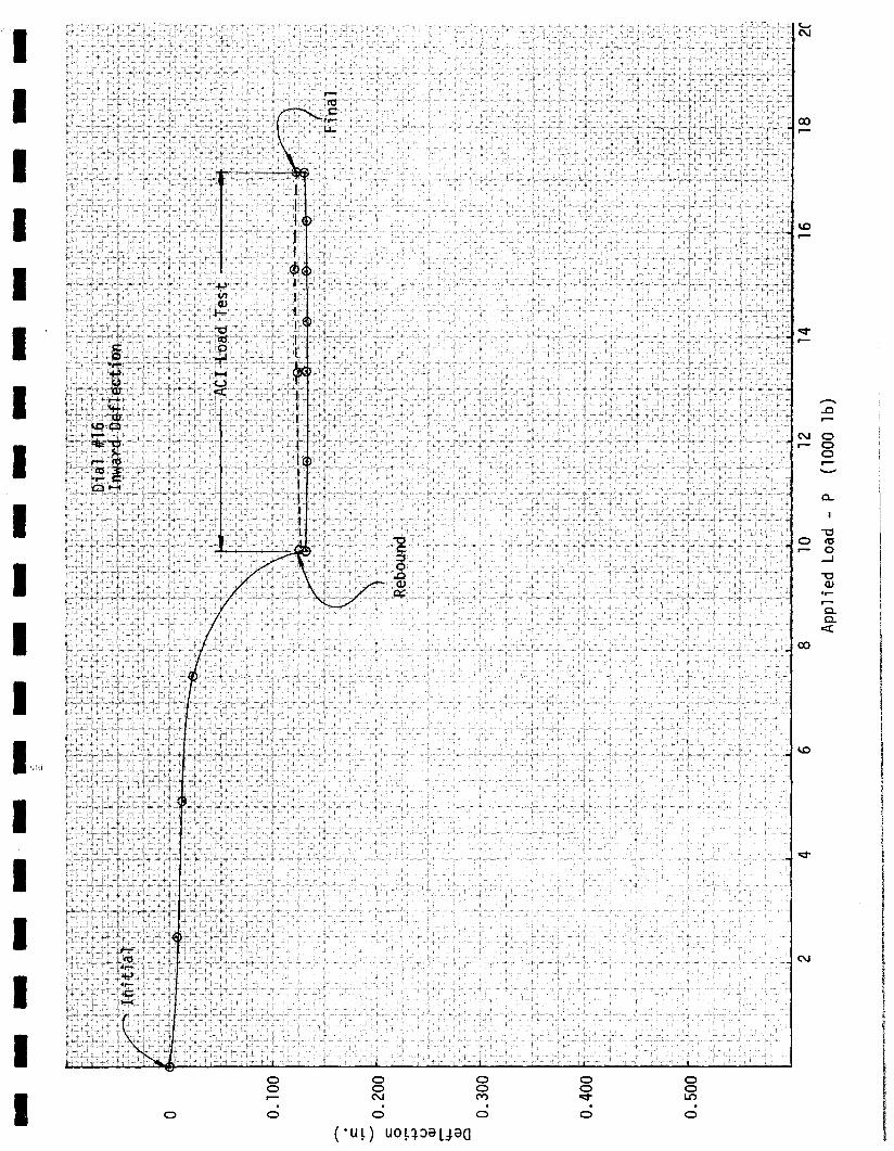
The American Concrete Institute load test procedures are concerned primarily. withdeflection data. The deflection information and discussion arecontained in afollowing appendix. However, it should be noted that the total mid-span movementdownward and outward was approximately 0.067 in. and 0.069 in., respectively. Inboth cases, the residual downward end outward deflections after 24 hours of reboundwere each 0.037 in. The mid-span movement of the beam was less than the totaldeflection allowed by American Concrete Institute test criteria (0.082 in. in thevertical direction and 0.121 in. in the horizontal direction). Therefore, a 75 percent recovery of deflection in the member was not required. The reader will recallthat neither the deflection nor the rebound criteria were met in the first testperformed on the spandrel beam in 1973.
The full service dead load was held on the spandrel beam for a period of timelonger than the minimum time required by the American Concrete Institute loadtest procedures in order to allow the spalling and cracking of the beam to morefully simulate the actual field conditions. Then, the designed correction haunches were grouted in identical toactual field conditions established recently at theproject. The full ACI test load was achieved in more than four approximately equalincrements by means of calibrated hydraulic jacks. Deflection and strain data wereobtained at each load increment. Return to dead load and rebound data were alsoobtained, although deflection under full test load did not require rebound in thetest. After performance of the load tests, nondestructive testing procedures were:employed to evaluate the membe~and concrete cores were obtained in order to obtainadditional material strength data.
IIII LABORATORY No. 6-13852
IIIIIIIIIIIIIIII AS A MUTUAL PROTECTION TO CLIENTS, THE PUBLIC AND OURSELVES. ALL REPORTS ARE SUBMITTED AS THE CONFIDENTIAL PROPERTY OF CLIENTS, AND AUTHOR.
IZATION FOR PUBLICATION OF STATEMENTS. CONCLUSIONS OR EXTRACTS FROM OR REGARDING OUR REPORTS IS RESERVED PENDING OUR WRITTEN APPROVAL.
AS A MUTUAL PROTECTION TO CLIENTS. THE PUBLIC AND OURSELVES. ALL REPORTS ARE SUBMITTED AS THE CONFIDENTIAL PROPERTY OF CLIENTS. AND AUTHOR.IZATION FOR PUBLICATION OF STATEMENTS. CONCLUSIONS OR EXTRACTS FROM OR REGARDING OUR REPORTS IS RESERVED PENDING OUR WRITTEN APPROVAL.
Recommendations
January 27, 1975DATE:
PAGE: 3
SUMMARY - Cont.
ENGINEERS AND CHEMISTS
662 Cromwell Avenue - St. Paul, Minn. 55114
LOAD TEST OF SPANDREL BEAMREPORT OF:
Of significant importance during this test was that additional end bearing spalling and appreciable outward movement of the end bearing regions of the beamdid not occur after the corrective procedures were incorporated in the test beamconstruction.
Based on the load test data, it is our opinion that the performance of the structural member now satisfies the test requirements set forth by the American ConcreteInstitute. The deflection of the member falls within the prescribed guidelines ofthe test evaluation criteria. Although we did observe the diagonal and other cracking previously mentioned above, we would not consider the magnitude of this crackingto be "visible evidence of failure" as referenced in Paragraph 20.4.5 of the ACI318-71 Building Code.
We should note that a pair of diagonal cracks did develop in the vertical portionof the spandrel beam under the full ACI test load. In addition, what appeared tobe the first signs of horizontal crack development in the vertical leg were alsonoted during the final hours of the full ACI 24 hour test load. Nondestructivetesting of the vertical portion of the end bearing regions of the spandrel beamindicated that no internal splitting of the member in the direction of the axisof the beam had occurred. This test information and all concrete core data areincluded in an appendix of this report.
The strain gauge data and visual observations during the testing both attest to thefact that the concrete materials comprising this spandrel beam definitely are working in tension. This would be in contrast to typical cracked-section design of flexural non-prestressed concrete members. Project Drawing Number S6B, dated June 10,1974, Note Number 11 makes reference to the spandrel beam cracks and states "app lysealant bead along cracks ... ". Since the concrete is in tension and it has nowbeen demonstrated by test that the haunches should permit the beam to function ina reasonably elastic manner under service live loads, it is our opinion that alldiagonal cracking and all other cracking in the vicinity of the ends of the beamsshould be pressure-grouted with an epoxy type material having a minimum bondstrength of lOOO psi. We advise that a full-depth pressure grout of prescribedbond strength be used in lieu oft,a surface bead of sealant because the load, testdemonstrates that tensile strength in the concrete and therefore integrity of theconcrete member is important in the performance of the beam. A load test is a shortterm method of determining the safe capacity of a structural member. However, cracking in a concrete structural member is also time-related and this aspect relates tolong-term performance and ultimately the useful life of the construction.
Normally pressure grouting of a member under tension simply results in the development of another crack in the concrete construction parallel to and very near theoriginal repaired crack. However, the very inclusion of the beam modificationspresupposes that the haunch assemblies will return the concrete materials to a
645-3601
TWIN CITY TESTING AND ENGINEERING LABORATORY. INC.
LABORATORY No. 6-13852
IIIIIII'IIIIIIIIIIII
AS A MUTUAL PROTECTION TO CLIENTS, THE PUBLIC AND OURSELVES. ALL REPORTS ARE SUBMITTED AS THE CONFIDENTIAL PROPERTY OF CLIENTS. AND AUTHOR.IZATION Ft?R PUBLICATION OF STATEMENTS. CONCLUSIONS OR EXTRACTS FROM OR REGARDING OUR REPORTS IS RESERVED PENDING OUR WRITTEN APPROVAL.
TEST INFORMATION
January 27, 19754
DATE:
PAGE:
ENGINEERS AND CHEMISTS
662 Cromwell Avenue - St. Paul, Minn. 55114
LOAD TEST OF SPANDREL BEAMREPORT OF:
SUMMARY - Cont.
workable range of tension. Pursuing this approach, development of companion parallelcracking would then be less likely.
In addition to restoring the integrity of the concrete construction, the epoxy pressure grouting would attempt to provide as much protection for the steel reinforcementas originally had been intended. Even with these pressure grouting modifications,we hold as doubtful that any predetermined useful life of the structure could now befully realized.
The end cracking of the spandrel beams at the project site does present a problemwith regard to pressure grouting. Therefore, we recommend that additional fieldinvestigation be performed to determine extent of splitting in the end regions ofthe beams and to develop the most feasible method of repair. We should note thatboth this investigative work and any epoxy pressure grouting can be performed whilethe structure is in service, since neither of these items affects the immediatesafety of the construction but only the long-term performance and safety of thestructure.
Our testing indicated that the vertical bolt extending through the haunches and intothe beam is both in shear and in tension. The test also demonstrates to us the importance that is being placed on this one item in the modifications. Since the bolt isfully embedded in the grout applied on the haunch and this grout extends completelyto the column, we are concerned about the performance of the entire construction overanticipated full temperature cycles. Thermal expansion and contraction of the spandrel beams could conceivably cause concern for the long-term performance of the beambo1t-grout-haunch-co1umn assembly, unless some other provision has been made in theconstruction, of which we are not presently aware.
Information concerning the test beams and bearing pads is si~ilar to that reportedin the initial test program. The beams for both the initial and the present loadtests had been cast at the same time. Therefore, one significant differencebetween the test beams was that the present beam had a field cure of approximately13 months longer than the initial test beam" In addition,this beam received theservice dead load after considerably longer cure than the beams in the stru~ture.
However, in terms of application of the haunch modification and performance of theACI load test on the modified spandrel beam setup, the age of the test beam vs,the age of the project beams is approximately the same.
Test Setup
Please refer to Appendix A for information concerning the test setup. Also,photographs illustrating the test setup are included in the last appendix.
645-3601
TWIN CITY TESTING~ ENGINEERING LABORATORY. INC.
LABORATORY No. 6-13852
IIIIIIIIiIIIIIIIIII
645-3601
TWIN CITY TESTING AND ENGINEERING LABORATORY. INC.
There are several aspects worth noting concerning the recent load test. The concrete columns and pads were heavily reinforced and utilized a minimum 7000 psicompressive strength concrete material in order to achieve end reactions whichwould exhibit negligible deflection or movement under the full test load. Furthermore, these pads were securely fastened to one another in order to assure againstspreading or other movement under full load. The bearing pockets and other endbearing conditions on the test colum~precisely duplicated those at the project.As has been previously mentioned, the Neoprene bearing pads for the individualdouble-tee legs were securely fastened to the steel beams simulating the double-tee legs. These steel beams were simply supported but were not permitted to undergoany lateral movement with outward deflection of the spandrel beam. This was achievedby means of end-ties on the beams and steel blocking back to the columns and laboratory loading frame. By virtue of the simply supported condition and a preselectedstiffness in the steel wide flange members, a vertical oriented load was estab11shedat each of the double-tee bearing locations during the load test.
A 6 in, wide flange beam was employed to simulate the concrete topping in the rampconstruction. This beam was secured to the concrete columns and blocked at midpoint to the laboratory loading frame. At the prescribed time during the load test,a 1 in. space between the steel beam and spandrel beam was grouted utilizing a minimum 4000 psi compressive strength sand-Portland cement grout" The location of thebottom edge of the grout corresponded to the bottom surface of the designated concrete topping which was placed on top of the double-tee concrete panels. The thickness of the simulated topping in the load test was 6 in. (the full width of thebeam flange), in contrast with approximately 8 in. thick topping at the projectIn addition, the six 3/4 in. coil rod inserts behind the topping in the test beamdid not receive threaded steel rod, whereas we understand the beams at the projectutilized threaded rod, the rod extending approximately 4 ft into the topping fromthe insert locations Based on our judgment that the spandrel beam applied a compressive load to the topping at this location, that the coil rod inserts received noshear forces at the topping-spandrel beam interface, and that the coil rod insertswere located in the spandrel beam such that they could not develop any significantcouple, we deleted these from the test setup. In our judgment, also, the variationin topping thickness does not playa significant role in determining adequacy ofthe spandrel ,member.
Instead of drilling holes in the concrete columns and positioning the haunches ina procedure similar to the project, we cast the bolts into the column and placedthe haunches over the pre-positioned bolts. Using this procedure, it was necessaryto enlarge the bolt holes which had been predrilled in the back plate. Once thehaunches were set in the exact locations prescribed for the project beam , wesecured the haunch assemblies to the columns. Since additional cutting had beendone on the haunch back plates and no filling was performed, we machine-drilled1/2 in. thick steel plates to the precise bolt tolerance, fully welded these washersto the back plates of the haunches, hand torqued the nuts in a manner similar to theproject repair work, and then fully welded the nuts to the steel washers. In addi-
January 27, 1975DATE:
PAGE: 5
TEST INFORMATION - Cont.
ENGINEERS AND CHEMISTS
662 Cromwell Avenue - St. Paul, Minn. 55114
LOAD TEST OF SPANDREL BEAMREPORT OF:
LABORATORY No. 6-13852
IIIIIIIIIIIIIIIIIII
AS A MUTUAL PROTECTION TO CLIENTS, THE PUBLIC AND OURSELVES, ALL REPORTS ARE SUSMITTED AS THE CONFIDENTIAL PROPERTY OF CLIENTS, AND AUTHOR.IZATION FOR PUBLICATION OF STATEMENTS, CONCLUSIONS OR EXTRACTS FROM OR REGARDING OUR REPORTS IS RESERVED PENDING OUR WRITTEN APPROVAL;
645-3601
TWIN CITY TESTING AND ENGINEERING LABORATORY. INC.
tion, we then provided solid blocking between the bottoms of the haunches and thelaboratory footing pads by means of forming and placing a solid, rapid setting,5000 psi minimum compressive strength commercial grout. The installation of thehaunches is illustrated in the accompanying photographs of the last appendix ofthis report. Since our firm was directed to investigate only the performance ofthe spandrel beam, it was our judgment that the modification work incorporatedinto the haunch application work would not affect the performance of the haunchesor bolts and would neither assist or hinder the spandrel beam in the performanceof the load test.
DATE: January 27, 1975
PAGE: 6
TEST INFORMATION - Conto
ENGINEERS AND CHEMISTS
662 Cromwell Avenue - St. Paul, Minn. 55114
LOAD TEST OF SPANDREL BEAMREPORT OF:
Drilling was performed on the bottom of each end of the spandrel beam at the prescribed haunch slot locations. A 1 in. diameter by 6 ino long Qwik-Bolt was insertedinto each of the two drilled holes. At the prescribed time during the test, these.bolts were tightened and a Five Star grout with a minimum 5000 psi compressivestrength was placed in the appropriate location noted by project drawing Number S68,dated June 10, 1974. Two slotted pieces of thin sheet metal were drawn around eacnof the Qwik-Bolts so as to just cover the slot in the top plate of each of thehaunches and thus prevent the grout from intruding into this slotted area. Thegrout was allowed to fully cure, after which time a 48 h04r dead load hold periodwas maintained prior to commencement of the ACI load test.
Two systems(of three hydraulic rams connected to one pressure manifold and calibratedgauge and pump)were utilized in the load test. The six rams were positioned, oneon each of the six simulated double tee legs. The end reactions calculated from theknown span lengths and applied concentrated hydraulic loads comprised the test increments. Please refer to an attached appendix for chronology information, togetherwith our observations during the entire test schedule. Please note that the calculated dead load was maintained on the spandrel beam for a period of approximately 11days before the actual ACI load tests commenced.
Deflection Measurements
Dial extensometers accurate to at least 0.001 in. were mounted in order to recordmovement at 22 different locations on the spandrel beam. During dead load application (Stages ,0 through 4) we recorded that compression of the end bearing Vosco padsdid occur, together with a slight movement outward of the end reactions. This rotation noted by the dial indicators caused end spalling of the concrete materials inthe spandrel beam, similar to the first load test performed in 1973 and similar tothe construction conditions. The graphical representation of movement at each ofthe dial indicator positions is included in one of the attached appendixes. Themid-span movement of the beam in the horizontal and vertical directions, referredto earlier in this report, was derived from deflection information at Dials 14 and15, respectivelyo These dial readings were corrected by average end movement ineach of the two directions.
LABORATORY No. 6-13852
IIIIIIIIIIIIIIIIIII
AS A MUTUAL PROTECTION TO CLIENTS. THE PUBLIC AND OURSELVES. ALL REPORTS ARE SUBMITTED AS THE CONFIDENTIAL PROPERTY OF CLIENTS. AND AUTHOR.IZATION FOR PUBLICATION OF STATEMENTS, CONCLUSiONS OR EXTRACTS FROM OR REGARDING OUR REPORTS IS RESERVED PENDING OUR WRITTEN APPROVAL.
AS A MUTUAL PROTECTION TO CLIENTS, THE PUBLIC AND OURSELVES, ALL REPORTS ARE SUBMITTED AS THE CONFIDENTIAL PROPERTY OF CLIENTS, AND AUTHOR·IZATION FOR PUBLICATION OF STATEMENTS, CONCLUSIONS OR EXTRACTS FROM OR REGARDING OUR REPORTS IS RESERVED PENDING OUR WRITTEN APPROVAL.
645-3601
TWIN CITY TESTING AND ENGINEERING LABORATORY. INC.
January 27, 1975DATE:
PAGE: 7
TEST INFORMATION - Cont.
ENGINEERS AND CHEMISTS
662 Cromwell Avenue - St. Paul, Minn. 55114
LOAD TEST OF SPANDREL BEAMREPORT OF:
As will be seen later in this report, the modulus of elasticity for the concrete intension was found to be approximately equal to the modulus of elasticity of the sameconcrete in compression for the lower stress ranges. Additional testing of the concrete is still in progress, It is apparent that the spandrel beam concrete materialsfailed in tension when the strain exceeded approximately 600 in. per in. Therefore,it is apparent that the ':oncrete behaved elastically only in the lower range of tensile stress and the modulus changes as the material approaches failure.
Nondestructive Testing
Upon completion of the ACI load tests, we removed the concrete spandrel beam fromthe column bearing pockets and examined the end regions of the beam with ultrasonictesting equipment. The ultrasonic meter is equipped with transmitting and receivinglow frequency sonic transducers, together with ~onitoring instrumentation. Internalfracturing and discontinuities in the test item are revealed by higher required sonictransmission time. The test results from the sonic scanning are shown in one of theattached appendixes. The sonic transmission of both ends of the test beam comparedwith the 8 in. thickness of the test member indicate that no discontinuities (splittingor other fractu~ing) had developed in the spandrel beam during the load test.
Concrete Coring and Testing
Subsequent to load testing of the spandrel beam, additional mapping of steel reinforcement in the structural member was performed and eight 4 in. diameter cores obtained.Since the areas of concrete cored had been precisely located and this recent load testwas terminated at load stage 10 instead of the appreciably higher load stages of theprevious 1973 test, it is our opinion that no microcracking had occurred in the areassampled and the concrete materials can therefore be considered sound and representative. Information concerning various tests performed on the concrete core specimens
Strain Gauges
Several strain gauges were mounted on the spandrel beam at various locations notedin one of the attached appendixes, Two types of gauges were used: 2 in. long foiltype Micro-Measurement electrical resistance gauges having a resistance of 120 ohmsutilizing a gauge factor of 2.11 nominal and 5 in. long wire type BLH electricalresistance gauges having a resistance of 120 ohms and utilizing a gauge factor of2.09 nominal. Prior to commencement of the ACI load tests, three 2 in. long gaugeswere mounted in the vicinity of a 5 in, long gauge to check average strain across thelonger gauge.
It should be noted that the 110 strain ll condition of the strain gauges was set whenthe spandrel beam was in a simply supported condition on its designated concretebearing pockets in the columns. At this time, no double tee load had yet beenapplied.
LABORATORY No. 6- 13852
IIIIIIIIIIIIIIIIIII
645-3601
TWIN CITY TESTING~ ENGINEERING LABORATORY. INC.III.LABORATORY No.
REPORT OF:
6-13852
ENGINEERS AND CHEMISTS
662 Cromwell Avenue - St. Paul, Minn. 55114
LOAD TEST OF SPANDREL BEAM
TEST INFORMATION - Cant.
DATE:
PAGE:
January 27, 19758
IIIIIIIIIIIIII
is included in one of the following appendixes.
TWIN CITY TESTING ANDENGINEERING LABORATORY INC
f..S A MUTUAL PROTECTION TO CUENTS, THE PUSLIC AND OURSELVES, ALL REPORTS ARE SUBMITTED AS THE CONFIDENTIAL PROPERTY OF CLIENTS, AND AUTHOR.
ZATION FOR PUBLICATION OF STATEMENTS, CONCLUSiONS OR EXTRACTS FROM OR REGARDING OUR REPORTS IS RESERVED PENDING OUR WRITTEN APPROVAL,r,_"
-------------------ACI LOAD TEST SETUP
~-----18I1x3411 Concrete Column
/
~./
__ 611 I-Beam, Simulatin--- Concrete Toppin
"7611 I-Beams Simul ating Doub1e-Tee Legs
\Cast-in-PlacConcreteColumn
}--_._-- - -_. -_.------ ----
---I
,-------_._-------.-
~
/'/---1as t-i n-Pl ace( Concrete
pandre~C~~ ] 1\'1 Pedes ta
1
-..::;::: ..........-'.5.:"';'-·,...<-,,-~~
.-Between 611 Beam and Spandrel Beam
Elevation - Load Test Setup
___.______ 22 1 -6 111-.-
r~ -1I I
: '1 14 1/211 41 -0 11 / 41 -0 11 4'-0 11 4 1 -0 11 4'-0 11 14 1/4' ::1 .. r-' .. I • I• t- -j :I I . I, I I I
-i-< 3 2,390 7,490 28,400 4,030-ifT1Vl-i 4 2,390 9,880 35,570 5,170 Weight of conc" topping, recordzGl immed., wai t 48 hr, record again}>
z 5 1,740 11 ,620 40,7900
fT1Z
6 1,740 13,360 46,010 Worki ng 1i ve load = 30 psfGl
zfT1fT1 7 950 14,310 48,860:uzGl
r 8 950 15,260 51 ,710}>
m0:u 9 950 16,210 54,560}>
-i0:u.-< 10 950 17,160 57,410 ACI test load = 63 psf livez load, record immed~, wait 24()
hr, record again; remove loads5-10, record immed., wait 24hr, record again.
Lab. No. 6-13852
I CHRONOLOGY OF SPANDREL BEAM LOAD TEST
I DAY DATE TIME STAGE REMARKS
IWednesday 12-11-74 10:00 Beam delivered to the laboratory
and positioned on concrete pedestal
Monday 12-16-74 Beam positioned on concrete,
I cast-in-place, columns.
12-24, 26, 27-74 Strain gauges mounted on beam.
IFriday 12-27-74 9:00 a.m. Zero readings recorded on
all strain gauges and dial indicators
IFriday 12-27-74 9:05 a.m. 0 START OF LOAD TEST
9:15 a.m. 1
I 10:15 a.m. 2 No visual damage of beam observed.
11:15 a.m. 3 Spalling observed at the south end
Ireaction immediately after appli-cation of load stage #3. No otherdamage noted in beam.
I Monday 12-30-74 10:30 a.m. 4
12:00 Diagonal hairline cracks (on the
I (Midnight) inside face of the stem) observedat both end reactions.
ITuesday 12-31-74 4:15 p.m. Grout placed between concrete beam
and 611 steel I-beam, to simulate theconcrete topping.
I Diagonal cracks observed to haveincreased in separation (See Photo-graph #14)
I Monday 1-6-75 Spalling observed at the north endreaction.
I9:00 a.m. Additional grout also placed between
haunch and concrete slab at each endreaction.
Tuesday 1-7 -75 1:30 p.m. Grout placed between steel haunch
I assembly and spandrel beam.
Friday 1-10-75 10:15 a.m. 5 START OF ACI LOAD TEST
I Hairline cracking observed in groutbetween steel haunch assembly and
Ispandrel beam (Both end reactions)
(See Photograph #22)
II
IIIIIIIIIIIIIIIIIII
Page 2
DAY DATE TIME STAGE REMARKS
Friday 1-10-75 11 :30 a.m. 6 Hairline flexural cracks observedon underside of beam (See Photograph#20)
1: 45 p.m. 7 Hairline cracking observed onboth the shelf and underside ofbeam.
2:45 p.m. a3:00 p.m. 9
3:45 p.m. 10 No new cracking observed. ACI testload in place for 24 hr.
Saturday 1-11-75 4:45 p.m. a5: 15 p.m. 6
5:45 p.m. 4
Sunday 1-12-75 5:45 p.m. 4 END OF ACI LOAD TEST (END OF24 HR REBOUND). Fine hairlinediagonal cracks observed at eachend reaction. Also, several smallareas of horizontal micro-crackingobserved above shelf on stem.
END OF TEST
-------------------CONDITION OF SPANDREL BEAM AFTER COMPLETION OF ACI LOAD TEST
\1I
j ( ------ - ( --- ----)
"
~- ----- --------
--'----iII
-------------------.-I:IEz()
-I-<-If11(J)
-IzGl
»zof11ZGl
zf11f11;0
zGl
r»IIIo;0»-Io;0
-<
z()
Top View - Concrete Spandrel Beam
> I' 1
----------
Bottom View - Bottom Face of Beam*
*Note: All Cracks Noted in the Above View were Observed to Occur at Load Stage #6 (With the Exception of the Two Noted)
Scale: None Laboratory Number 6-13852
1...----------TWIN CITY TESTING AND ENGINEERING LABORATORY,INC.------------I
311
3"
M5_ 5
.~5
.46
Laboratory Number 6-13852
6
45. ~5
i
J!3 ~~ JL-_j5----, . I
I~444
Spalled Concrete(1/2" in Depth)
ULTRA-SONIC TEST RESULTS
4" Square Grid
Shelf--
g,5 44____~4
Elevation - South End Reaction - Inside Face
Scale: 1 1/2" = 11 -0 11
Ultra-Sonic Test Locationand Corresponding Reading(in Micro-Sec)
ii
I------ ~--'---_-'---....:L---__,-J_3 .h__
Diagonal HairlineCrack
48
Lesend
IIIIIIIIIIIIIIIIIII
Elevation - North End Reaction - Inside Face
Laboratory Number 6-13852
L1-" Square Grid
44 46I
~645 47 t5'# " . ---, -~
, I II
fr~_ ...._.-!~--t5 .... ~5 --J6 ~5_ ...I
t6
I
~6 f5 4545. tII
45 45 45 45! • • •[
1
45 45 45 ~4-------,. +-- ----.-
~5 ~5 ~5 f4 ~4i ,i
~6_,
46 ~6 f6' ....I iII III
f616 t6!I
ULTRA-SONIC TEST RESULTS
Diagonal Hairline Crack
Scale: 1 1/2" = 1'-0 11
45 46·--jO----r
, I
II l5~6 .~ ...
45"
45.
Ultra-Sonic Test Locationand Corresponding Reading(in Micro-Sec)
/Spalled Concrete(7/8" in Depth)
Legend
"----..-;.------TWIN CITY TESTING AND ENGINEERING LABORATORY, INC.------------.I
IIIIIIIIIIIIIIIIIII
-------------------North
1911
T
Core #7
TEST CORE LOCATIONSCore #8
'. .',
Core #2 .Core #1
111 11
T
Side View - Inside Face of Concrete Spandrel Beam
Core #3
7 1 -6 11
I-i
81
-311
I I iI I I
II! t I
-~~-f ~-1~411
Core #5
I 71-7"
- -IiI 8'-6 11
,- -I
I '!i Ii iii:~J.
-"./ I , 1
-i~
z()
-i-<-if11(Jl
-izGl
»zof11zGlzf11f11;uzGl
r»mo;u»-io;u-<
z() Core #6 Core #4
Top View - Concrete Spandrel Beam
Scale: None Laboratory Number 6-13852
'----------TWIN CITY TESTING AND ENGINEERING LABORATORY, INC, -----------'
Lab. No. 6-13852
TEST CORE DATA
*Note: The above values for the modulus of elasticity in tension wasdetermined in our laboratory up to a unit tensile stress ofapproximately 200 psi, and a total strain of 40 micr~nches/inch.
65.3 .,{ 10
84.026.9238,500880
74.027.04147.31. 750.98
54.028.02147.321.0109,250
64.027.8841,000825875
44.028.01 6*5.4 x 10
86108955
9300
14.027.51 6*5.4 x 10
(ASTM:C42-68 Standard Method of Obtainingand Testing Drilled Cores and Sawed Beamsof Concrete)
24.027.2242,000920
(ASTM:C42-68 Standard Method of Obtainingand Testing Drilled Cores and Sawed Beamsof Concrete)
34.028.01147.321.0118,000
Core NumberDi arne ter , in.Length, in.Density (saturated), pcfLID Rati 0Correction FactorLoad at Fai 1ureCorrected CompressiveStrength, psiAverage, ps i
Modulus of Elasticity, psi
Core NumberDi ameter, in.Length, in.Load at Failure, IbTensile Stress, psi
Average Tensile Stress, psi
Core NumberDiameter, in.Length, in.
*Modulus of Elasticity, psi
MODULUS OF ELASTICITY IN TENSION
COMPRESSIVE STRENGTH
SPLITTING TENSILE STRENGTH
IIIIIIIIIIIIIIIIIII
-------------------DIAL INDICATOR LpCATIONS
I
! l----~ NorthL_~
#20#19 #16 #13
•#10 "' #7i
i
ELEVATION - EXPOSED ~GGREGATE FACE OF SPANDREL BEAM
'-----------TWIN CITY TESTING AND ENGINEERING LABORATORY, INC. ...1
Lab. No. 6-13852
Axis x-x
O. 121 11
=
=
Since the maximum deflection observed in Axis y_y = 0.067< 0.082** The Requirement for Recovery is Waived **
DEFLECTION RECOVERYAxi s y- y
II
,..--,..-1>. D
.. ~~
I
ISection-Concrete Spandrel Beam
According to Paragraph 20.4.6(b) of the Building Code Requirements for ReinforcedConcrete (ACI 318-71) the requirement for deflection recovery (for a flexural member)shall be .waived, provided the maximum measured deflection is less than Lt 2/20,000h.
where Lt = span of member under load test, in.h = overall thickness of member, in.
We were directed by the structural engineer (hired by the owner) to use the followingvalues for the above:
Since the maximum deflection observed = 0.069 in. < 0.121 in. in Axis x-x** The Requirement for Recovery is Waived **
(B) Analysis Along Axisy_y (shown above)
2 _ (258)2Lt /20,000hy_y - 20,000 (40.5)
Lt = center to center distance of the steel brackets, in.= clear span - 12 11 = 22 1-6 11 -12 = 21 1 -6 11
= 258 in,hX_X = 27.5 in.
hy~Y = 40.5 in 0
Our calculations, utilizing the above values are as follows:
(A) Analysis Along AXisX~X (shown above)
2 (258)2Lt /20,000hX~X = 20,000 (27.5)
IIIIIIIIIIIIIIIIIII
-_ .. _---------------DEFLECTION ALONG AXISy_y(Vertical Direction)
...-17",·
p ,
~'. '"~ I' •
'I>' ,v', ,',
• ''v tP'. ,"• p
North ..
r-------- ------ -------------- --I- - ----- - - ------ ---------------- TI I II
Def1 ecti on (re1 ati ve to readi ngs taken at Load Sta~_e_ #4t-jJJ~i2ri or to #5
MaximumLoading Condition Dial #21 Di a1 #15 Dial #9 Midspan*
Load Stage #4 (just prior to #5) 0 0 0 0
Load Stage #10 (end of 24 hrtes t peri od) +0.002 +0.068 0 0.067
*Note: All strain gages were mounted with the concrete spandrel beam simply supported, and no load applied.Initial readings were then taken in this no-load condition.
The above strain gage readings are positive changes from the initial reading.
Photograph #1 - North-One-Ha1f of Test Setup, Front-View, Displaying SimulatedDouble-Tee, Loading Beams.
Photograph #2 - South-One-Ha1f of Test Setup, Front-View.
Laboratory Number 6-13852l-----------TWIN CITY TESTING AND ENGINEERING LABORATORY, INC.-----------...I
Photograph #3 - Test Setup, Side-View, Displaying Simulated Double-Tee, LoadingBeams and Calibrated Hydraulic Rams.
Photograph #4 - Test Setup, Top-View, Exhibiting I-Beam, (On the Right Side of thePicture) Used for Simulation of the Concrete Topping. Note GroutBetween I-Beam and Concrete Spandrel Beam.
Laboratory Number 6-138521..-. TWIN CITY TESTING AND ENGINEERING LABORATORY. INC. -------------1
Photograph #7 - Side-View, Mounted Dial Indicators, Measuring Outward and Downward Displacement· to the 0.001 inch.
Photograph #8 -
Top-View, Facing South, Displaying I-Beam Used for theSimulation of the ConcreteTopping.- (Note - Grout wasnot yet in Place BetweenI-Beam and Spandrel Beam)
Laboratory Number 6-13852'-----------TWIN CITY TESTING AND ENGINEERING LABORATORY, INC. -----------...1
Photograph #9 -
Side-View of Steel Haunch Priorto Placement of 5-Star Grout.(South-End Reaction)
Photograph #10 - Side-View of Steel Haunch After Grout was Installed.Reaction)
(South-End
Laboratory Number 6-13852'------------TWIN CITY TESTING AND ENGINEERING LABORATORY, INC.-----------....
Photograph #11
Side-View of Steel HaunchAfter Placement of Grout.(North-End Reaction)
Photograph #12 -
End View, North-End Reaction,Exhibiting Strain Gage Numbers17, 18 and 19.
Laboratory Number 6-138521...- TWIN CITY TESTING AND ENGINEERING LABORATORY, INC. -----------...1
Laboratory Number 6-13852'------------TWIN CITY TESTING AND ENGINEERING LABORATORY,INC.------------I
Photograph #23 - Close-up of Grout Between the Steel Haunch and Spandrel Beam,North-End Reaction (Load Stage #6)
Laboratory Number 6-13852"------------ TWIN CITY TESTING AND ENGINEERING LABORATORY. INC. -------------1
Photograph #24 - Side-View of Concrete Spandrel Beam, During Coring Operation(North-End Reaction) Note - The Two Diagonal Cracks (near theColumn) Outlined in Black.
Photograph #25 - Side-View of Concrete Spandrel Beam, South-End Reaction. Notethe Two Diagonal Cracks (near the Column) Outlined in Black.
Laboratory Number 6-13852'------------TWIN CITY TESTING AND ENGINEERING LABORATORY, INC. -------------'