UNIT SEVEN UNIT SEVEN FRONT SUSPENSION SYSTEM FRONT SUSPENSION SYSTEM DESIGN DESIGN 1 TABLE OF CONTENTS TABLE OF CONTENTS LESSON ONE - SUSPENSION SYSTEM PARTS ...................................................................... 2 SPRINGS ............................................................................................................................ 3 Damping .......................................................................................................................... 3 Spring Design................................................................................................................... 3 Coil Springs ..................................................................................................................... 4 Air Springs ....................................................................................................................... 6 Leaf Springs ..................................................................................................................... 7 TORSION BARS ................................................................................................................ 11 SHOCK ABSORBERS ....................................................................................................... 13 STABILIZER BARS ............................................................................................................ 15 STEERING KNUCKLE ........................................................................................................ 17 BALL JOINTS .................................................................................................................... 18 BUSHINGS........................................................................................................................ 20 CONTROL ARMS............................................................................................................... 22 LESSON TWO - TYPES OF SUSPENSION SYSTEMS ............................................................ 26 SOLID AXLE FRONT SUSPENSION.................................................................................... 27 SHORT LONG ARM (SLA) FRONT SUSPENSION................................................................ 28 TWIN I-BEAM SUSPENSION.............................................................................................. 30 TORSION BAR FRONT SUSPENSION SYSTEMS................................................................ 32 MACPHERSON STRUT FRONT SUSPENSION.................................................................... 33 Modified MacPherson Strut Suspension............................................................................ 35 VARIABLE DAMPING SHOCKS OR STRUTS ...................................................................... 36 Air Shocks and Struts ..................................................................................................... 36 Air Spring Suspension..................................................................................................... 37 Load Leveling Suspension ............................................................................................... 38 Nivomat Suspension ....................................................................................................... 39 LESSON THREE - DESIGN AND FUNCTION OF WHEEL BEARINGS....................................... 41 BEARINGS........................................................................................................................ 42 Tapered Roller Bearings .................................................................................................. 42 Bearing Cleaning and Inspection ...................................................................................... 44 Bearing Lubrication ......................................................................................................... 45 Seal Replacement .......................................................................................................... 46 Incorrect Component Alignment ....................................................................................... 47 Bearing Adjustment (Preload) .......................................................................................... 47 GLOSSARY.......................................................................................................................... 49
Transcript
UNIT SEVENUNIT SEVENFRONT SUSPENSION SYSTEMFRONT SUSPENSION SYSTEM
DESIGNDESIGN
1
TABLE OF CONTENTSTABLE OF CONTENTS
LESSON ONE - SUSPENSION SYSTEM PARTS ......................................................................2SPRINGS............................................................................................................................3
LESSON TWO - TYPES OF SUSPENSION SYSTEMS............................................................26SOLID AXLE FRONT SUSPENSION....................................................................................27SHORT LONG ARM (SLA) FRONT SUSPENSION................................................................28TWIN I-BEAM SUSPENSION..............................................................................................30TORSION BAR FRONT SUSPENSION SYSTEMS................................................................32MACPHERSON STRUT FRONT SUSPENSION....................................................................33
Modified MacPherson Strut Suspension............................................................................35VARIABLE DAMPING SHOCKS OR STRUTS ......................................................................36
Air Shocks and Struts.....................................................................................................36Air Spring Suspension.....................................................................................................37Load Leveling Suspension ...............................................................................................38Nivomat Suspension .......................................................................................................39
LESSON THREE - DESIGN AND FUNCTION OF WHEEL BEARINGS.......................................41BEARINGS........................................................................................................................42
UNIT SEVENUNIT SEVENFRONT SUSPENSION SYSTEMFRONT SUSPENSION SYSTEM
DESIGNDESIGN
2
LESSON ONELESSON ONESUSPENSION SYSTEM PARTSSUSPENSION SYSTEM PARTS
TERMINAL OBJECTIVESuccessful completion of this Unit’s enabling objectives(technical competencies) will allow you to meet theIntegrated Curriculum Standards (ICS) listed in the rightmargin.
ENABLING OBJECTIVESUpon completion of Lesson Two, you should be able to:•
KEY TERMS You will see the following key terms used throughout thislesson. You may also refer to the glossary at the back of thisbook for definitions of these terms.• Air Spring• Ball Joint• Body Roll• Bushing• Coil Spring• Control Arm• Dampening• Deflection Rate
UNIT SEVENUNIT SEVENFRONT SUSPENSION SYSTEMFRONT SUSPENSION SYSTEM
DESIGNDESIGN
3
SPRINGSSuspension systems are designed to travel with the wheel assemblyas the vehicle encounters abnormal road conditions. Springsaccomplish a portion of this task by providing a cushion for roadimpacts. All suspension systems incorporate some type of spring.While the spring design may vary, its main task remains the same.
DampingSpring's accomplish one of the two major tasks of the suspensionsystem - they absorb bumps or jounces caused by varying roadsurfaces. Shock absorbers are used to accomplish the other task -to control the rebound of the springs. Without damping, also knownas dampening, the actions of the spring devices would not becontrolled.
Spring DesignSprings are designed to have deflection rate and recoil frequency.A spring's deflection rate is the amount of bend that is induced withdifferent weights. The rate is usually expressed as pounds neededto compress the spring one inch. A spring's recoil frequency is thetime it takes to recoil or deflect in the opposite direction. Load doesnot affect frequency. The frequency depends on the spring's length,thickness and width.
UNIT SEVENUNIT SEVENFRONT SUSPENSION SYSTEMFRONT SUSPENSION SYSTEM
DESIGNDESIGN
4
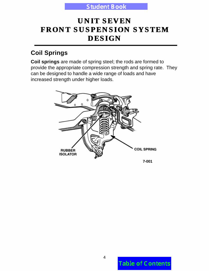
Coil SpringsCoil springs are made of spring steel; the rods are formed toprovide the appropriate compression strength and spring rate. Theycan be designed to handle a wide range of loads and haveincreased strength under higher loads.
7-001
UNIT SEVENUNIT SEVENFRONT SUSPENSION SYSTEMFRONT SUSPENSION SYSTEM
DESIGNDESIGN
5
In some cases coil springs are mounted on the control arm, with theframe riding on top; in other cases they are mounted on struts, aspart of a shock absorber and coil assembly. When mounted on ashock, the top is bolted to the chassis and held in place by a springseat containing a rubber isolator. Although some struts are designedto rotate, springs do not.
Coil springs are under load, even if the vehicle is raised or jacked up.The spring's length when unloaded is longer than the distance thesuspension can expand. This tension holds the spring in place andsupports the weight of the vehicle.
7-002
UNIT SEVENUNIT SEVENFRONT SUSPENSION SYSTEMFRONT SUSPENSION SYSTEM
DESIGNDESIGN
6
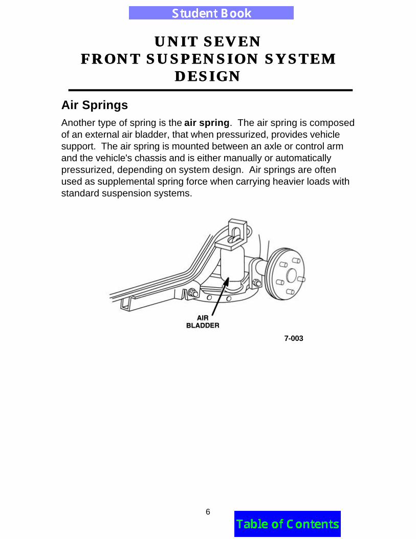
Air SpringsAnother type of spring is the air spring. The air spring is composedof an external air bladder, that when pressurized, provides vehiclesupport. The air spring is mounted between an axle or control armand the vehicle's chassis and is either manually or automaticallypressurized, depending on system design. Air springs are oftenused as supplemental spring force when carrying heavier loads withstandard suspension systems.
7-003
UNIT SEVENUNIT SEVENFRONT SUSPENSION SYSTEMFRONT SUSPENSION SYSTEM
DESIGNDESIGN
7
Leaf SpringsLeaf springs are generally made from steel, but some arecomposed of fiberglass, carbon fiber, graphite or other materials.The spring curve flattens as the spring is compressed. Some leafsprings are multi-leaf. Each leaf below the main leaf increases inarch. This creates more strength as the spring is compressed. Themain leaf is the longest, flattest strip and has eyes (loops) formed ateach end for attachment to the vehicle.
7-004
UNIT SEVENUNIT SEVENFRONT SUSPENSION SYSTEMFRONT SUSPENSION SYSTEM
DESIGNDESIGN
8
The U-bolts fasten the leaf spring to the axle. The front eye of thespring is attached to a hanger on the frame. The rear eye is attachedto a movable shackle or link that allows the main leaf to expand inlength when the vehicle encounters a bump or dip.
7-005
UNIT SEVENUNIT SEVENFRONT SUSPENSION SYSTEMFRONT SUSPENSION SYSTEM
DESIGNDESIGN
9
As the leaves compress, their ends rub against each other. This is aresult of the different lengths and arcs. Liners, interleaves or insertsmade of plastic, wax or zinc are often installed between the leaves toreduce the friction.
Some vehicles designed with independent rear suspensions haveone transversely mounted leaf spring.
7-006
7-007
UNIT SEVENUNIT SEVENFRONT SUSPENSION SYSTEMFRONT SUSPENSION SYSTEM
DESIGNDESIGN
10
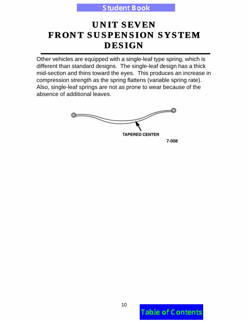
Other vehicles are equipped with a single-leaf type spring, which isdifferent than standard designs. The single-leaf design has a thickmid-section and thins toward the eyes. This produces an increase incompression strength as the spring flattens (variable spring rate).Also, single-leaf springs are not as prone to wear because of theabsence of additional leaves.
7-008
UNIT SEVENUNIT SEVENFRONT SUSPENSION SYSTEMFRONT SUSPENSION SYSTEM
DESIGNDESIGN
11
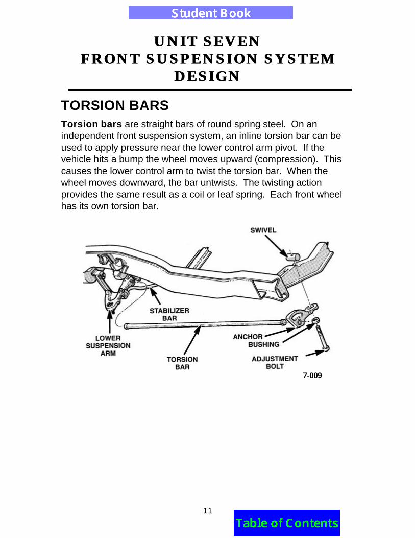
TORSION BARSTorsion bars are straight bars of round spring steel. On anindependent front suspension system, an inline torsion bar can beused to apply pressure near the lower control arm pivot. If thevehicle hits a bump the wheel moves upward (compression). Thiscauses the lower control arm to twist the torsion bar. When thewheel moves downward, the bar untwists. The twisting actionprovides the same result as a coil or leaf spring. Each front wheelhas its own torsion bar.
7-009
UNIT SEVENUNIT SEVENFRONT SUSPENSION SYSTEMFRONT SUSPENSION SYSTEM
DESIGNDESIGN
12
Torsion bars can be mounted inline or transversely. Frontsuspension transverse torsion bars are shown below. The bars areparallel to the crossmember and anchored at one end, opposite thewheels they serve.
A pivot cushion bushing supports and isolates the bar where it turnsrearward toward the wheel. The end attaches to the lower controlarm in a rubber bushing. This design isolates all three connectingpoints of the bar, which limits the noise and road shocks reaching thevehicle. The bar acts as a lever from the control arm to the pivotcushion bushing as the vehicle encounters bumps and dips. Thetransverse torsion bar reacts the same as the inline torsion bar, butalso replaces the strut rod/bar found on inline applications.
7-010
UNIT SEVENUNIT SEVENFRONT SUSPENSION SYSTEMFRONT SUSPENSION SYSTEM
DESIGNDESIGN
13
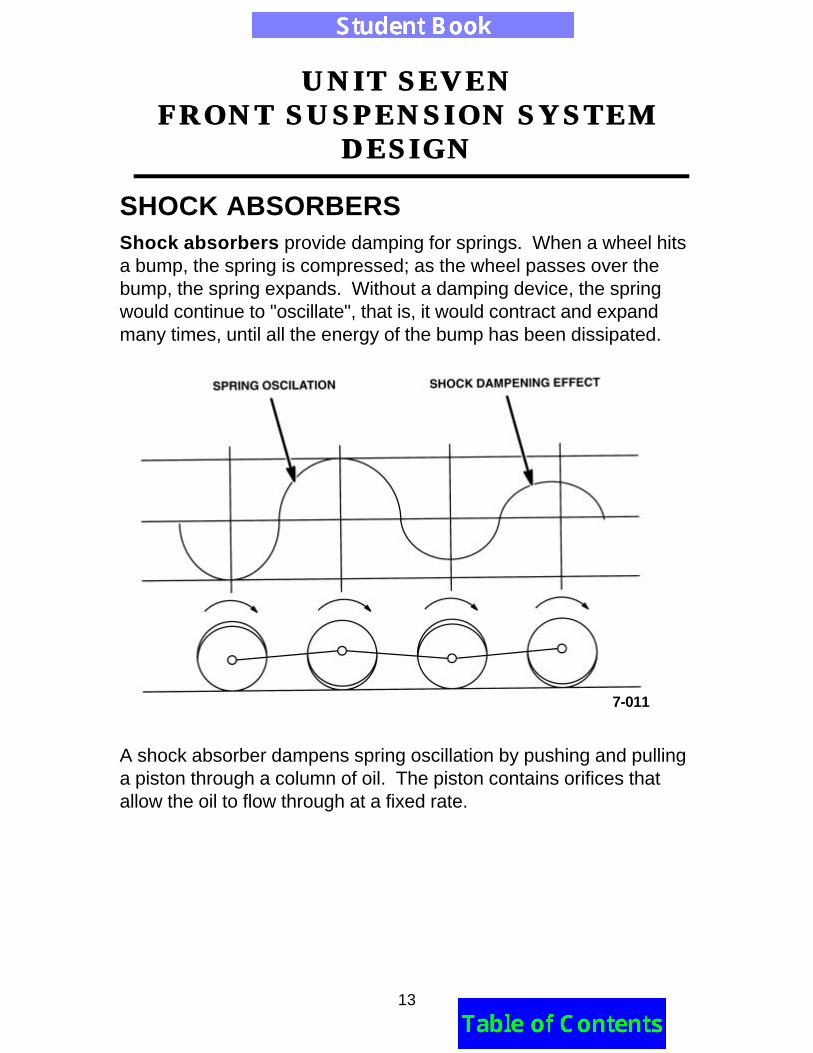
SHOCK ABSORBERSShock absorbers provide damping for springs. When a wheel hitsa bump, the spring is compressed; as the wheel passes over thebump, the spring expands. Without a damping device, the springwould continue to "oscillate", that is, it would contract and expandmany times, until all the energy of the bump has been dissipated.
A shock absorber dampens spring oscillation by pushing and pullinga piston through a column of oil. The piston contains orifices thatallow the oil to flow through at a fixed rate.
7-011
UNIT SEVENUNIT SEVENFRONT SUSPENSION SYSTEMFRONT SUSPENSION SYSTEM
DESIGNDESIGN
14
The piston rides up and down inside a two-chamber oil reservoir.There is a base valve that meters the flow of oil into the lowerchamber of the oil reservoir. When the piston rises quickly (forexample, when the wheel falls into a pothole), the base valve opens,to allow oil to flow into the lower chamber of the reservoir.
A spring-loaded disc valve in the piston meters the flow of oil into theupper chamber of the reservoir. When the piston descends quickly(for example, when the wheel hits a big bump), the disc valve opensto allow oil to flow from the lower chamber of the reservoir, into theupper chamber.
7-012
UNIT SEVENUNIT SEVENFRONT SUSPENSION SYSTEMFRONT SUSPENSION SYSTEM
DESIGNDESIGN
15
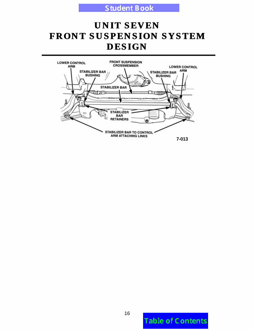
STABILIZER BARSStabilizer bars are used to help limit the effects of body roll whilecornering. The bar acts much like a torsion bar. The bar is U-shaped and is usually connected to the two lower control arms andframe through bushings. It can be mounted in front of or behind thesuspension. As the vehicle enters a turn, the vehicle rolls, causingthe outside wheel to compress upward (jounce). This forces thestabilizer bar end upward. The bar then rotates in its frameattachment bushings and tries to force the opposite side down.Since it cannot force the other side down, it applies the pressure tothe jounced wheel control arm, which counteracts the spring tensionand vehicle weight. This helps to maintain the vehicle in a levelposition.
Sway bar diameters can affect oversteer and understeer. Theyshould only be replaced with Original Equipment Manufacturer(OEM) parts. Stabilizer bars are also used instead of struts on manyvehicles, because they connect to control arms in the same fore andaft direction. Some vehicles use a sway bar with a vertical link. Thevertical link attaches to a ball joint.
UNIT SEVENUNIT SEVENFRONT SUSPENSION SYSTEMFRONT SUSPENSION SYSTEM
DESIGNDESIGN
16
7-013
UNIT SEVENUNIT SEVENFRONT SUSPENSION SYSTEMFRONT SUSPENSION SYSTEM
DESIGNDESIGN
17
STEERING KNUCKLEMany different steering knuckle designs exist, but they all have thesame function - to attach the steering/suspension system to thewheel assembly. Knuckles are forged as heavy, one-piececonstructions and provide attaching points for components such ascontrol arms, steering arms, tie rods, struts, and brake calipers,depending on the system used. Steering knuckles on rear-wheel-drive vehicles are often called "spindles" because they house theshafts on which the front wheels rotate. For front-wheel drive andfour-wheel drive vehicles, hub units are mounted on the steeringknuckles rather than spindles. Most spindles bolt directly to thesteering knuckles, while others are integral or one piece.
7-014
UNIT SEVENUNIT SEVENFRONT SUSPENSION SYSTEMFRONT SUSPENSION SYSTEM
DESIGNDESIGN
18
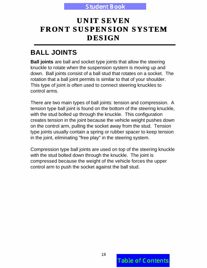
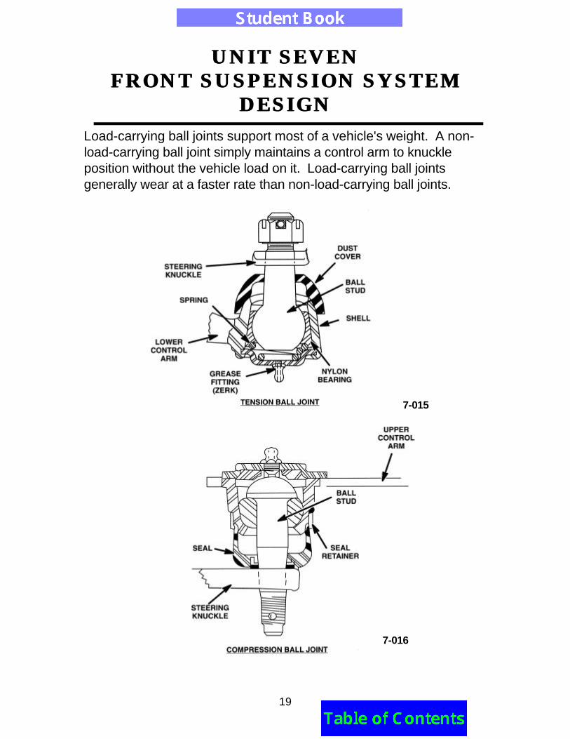
BALL JOINTSBall joints are ball and socket type joints that allow the steeringknuckle to rotate when the suspension system is moving up anddown. Ball joints consist of a ball stud that rotates on a socket. Therotation that a ball joint permits is similar to that of your shoulder.This type of joint is often used to connect steering knuckles tocontrol arms.
There are two main types of ball joints: tension and compression. Atension type ball joint is found on the bottom of the steering knuckle,with the stud bolted up through the knuckle. This configurationcreates tension in the joint because the vehicle weight pushes downon the control arm, pulling the socket away from the stud. Tensiontype joints usually contain a spring or rubber spacer to keep tensionin the joint, eliminating "free play" in the steering system.
Compression type ball joints are used on top of the steering knucklewith the stud bolted down through the knuckle. The joint iscompressed because the weight of the vehicle forces the uppercontrol arm to push the socket against the ball stud.
UNIT SEVENUNIT SEVENFRONT SUSPENSION SYSTEMFRONT SUSPENSION SYSTEM
DESIGNDESIGN
19
Load-carrying ball joints support most of a vehicle's weight. A non-load-carrying ball joint simply maintains a control arm to knuckleposition without the vehicle load on it. Load-carrying ball jointsgenerally wear at a faster rate than non-load-carrying ball joints.
7-015
7-016
UNIT SEVENUNIT SEVENFRONT SUSPENSION SYSTEMFRONT SUSPENSION SYSTEM
DESIGNDESIGN
20
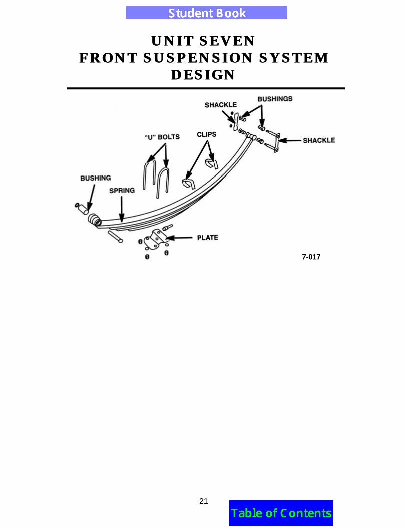
BUSHINGSBushings are often used in joints between moving components.They are designed to eliminate the friction that causes prematurewear. However, the bushings themselves are subject to wear andcan cause play in the component's connecting points. Bushings aremanufactured with bronze or rubber compounds, depending ondesign requirements. Bushings should be tight and usually do notrequire lubrication.
Leaf spring eyes contain bushings. The bushings allow the spring torotate on the shackle and hanger as it compresses. All motionoccurs inside the rubber bushing. The bushings do not rotate on thebolt or in the spring eye. If a bushing rotates at one of these points asqueak is likely to develop. Bushings are used on many suspensioncomponents for example:• Control arms• King pins• Stabilizer bars• Shock absorbers• Lateral links• Strut Rods• Track bars
UNIT SEVENUNIT SEVENFRONT SUSPENSION SYSTEMFRONT SUSPENSION SYSTEM
DESIGNDESIGN
21
7-017
UNIT SEVENUNIT SEVENFRONT SUSPENSION SYSTEMFRONT SUSPENSION SYSTEM
DESIGNDESIGN
22
CONTROL ARMSControl arms are used to hold knuckles and wheel assemblies intheir proper positions. They also provide a movable link between thevehicle's frame and the wheel assembly. Control arms are designedto control forces the wheel encounters when rotating. The varioussuspension systems mount control arms or links in differentdirections to control these forces. (Control arms are often calledlinks). Many control arms are made from stamped steel. Controlarms can also be made from cast and nodular iron, aluminum orgalvanized steel tubing.
Many vehicles today are equipped with both upper and lower controlarms. The most common upper control arm is "A" (or triangular)shaped for improved strength. The base of the arm is mounted on apivot shaft or bolt with bushings attached to the frame. The otherend of the arm connects to the knuckle through a ball joint. The balljoint allows the knuckle to rotate, so that the spindle and wheel canturn. The joint also allows for up and down swiveling movement dueto variations in road surfaces.
UNIT SEVENUNIT SEVENFRONT SUSPENSION SYSTEMFRONT SUSPENSION SYSTEM
DESIGNDESIGN
23
7-018
UNIT SEVENUNIT SEVENFRONT SUSPENSION SYSTEMFRONT SUSPENSION SYSTEM
DESIGNDESIGN
24
Lower control arms can also be "A" shaped. If this type of lowercontrol arm is used, attachment points are similar to those of theupper control arm. Some lower control arms are shaped differently,like rods or bars. In this design, the attaching points are similar tothe "A"-shaped arm, but the strength of the arm is not comparable.For the rod-shaped control arm to be effective, an additionalcomponent must be added. Generally this component is a strut baror rod. The rod controls fore and aft forces on the control arm.
7-019
UNIT SEVENUNIT SEVENFRONT SUSPENSION SYSTEMFRONT SUSPENSION SYSTEM
DESIGNDESIGN
25
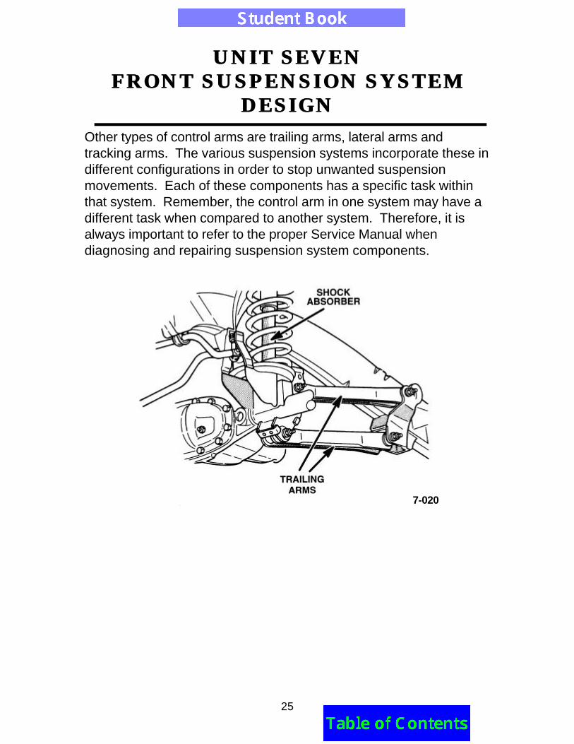
Other types of control arms are trailing arms, lateral arms andtracking arms. The various suspension systems incorporate these indifferent configurations in order to stop unwanted suspensionmovements. Each of these components has a specific task withinthat system. Remember, the control arm in one system may have adifferent task when compared to another system. Therefore, it isalways important to refer to the proper Service Manual whendiagnosing and repairing suspension system components.
7-020
UNIT SEVENUNIT SEVENFRONT SUSPENSION SYSTEMFRONT SUSPENSION SYSTEM
DESIGNDESIGN
26
LESSON TWOLESSON TWOTYPES OF SUSPENSION SYSTEMSTYPES OF SUSPENSION SYSTEMS
TERMINAL OBJECTIVESuccessful completion of this Unit’s enabling objectives(technical competencies) will allow you to meet theIntegrated Curriculum Standards (ICS) listed in the rightmargin.
ENABLING OBJECTIVESUpon completion of Lesson Two, you should be able to:•
KEY TERMS You will see the following key terms used throughout thislesson. You may also refer to the glossary at the back of thisbook for definitions of these terms.• Jounce• MacPherson Strut• Rebound• Torsion Bar• Variable Damping Shocks
ICS
101Basic Physics
102Mechanics and Forces
155Steering andSuspension Systems
156Wheel Alignment,Wheels, and Tires
UNIT SEVENUNIT SEVENFRONT SUSPENSION SYSTEMFRONT SUSPENSION SYSTEM
DESIGNDESIGN
27
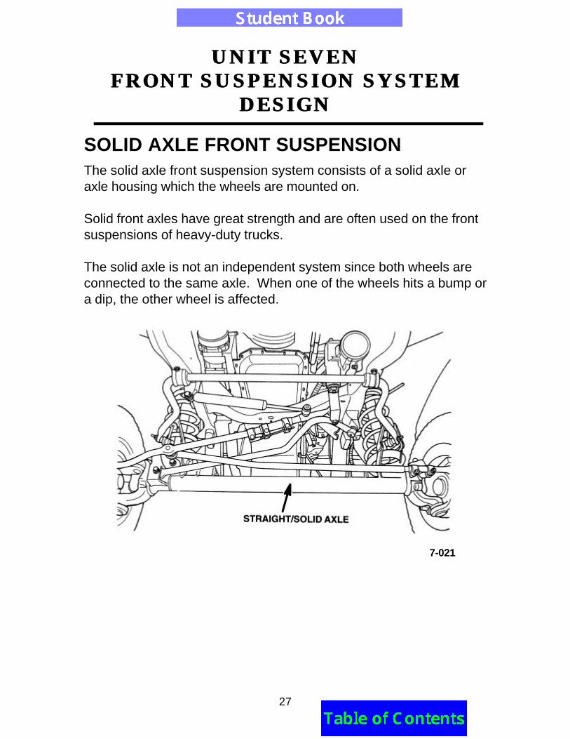
SOLID AXLE FRONT SUSPENSIONThe solid axle front suspension system consists of a solid axle oraxle housing which the wheels are mounted on.
Solid front axles have great strength and are often used on the frontsuspensions of heavy-duty trucks.
The solid axle is not an independent system since both wheels areconnected to the same axle. When one of the wheels hits a bump ora dip, the other wheel is affected.
7-021
UNIT SEVENUNIT SEVENFRONT SUSPENSION SYSTEMFRONT SUSPENSION SYSTEM
DESIGNDESIGN
28
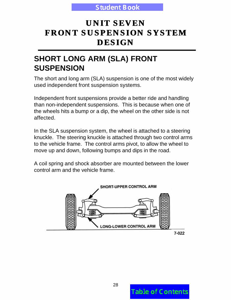
SHORT LONG ARM (SLA) FRONTSUSPENSIONThe short and long arm (SLA) suspension is one of the most widelyused independent front suspension systems.
Independent front suspensions provide a better ride and handlingthan non-independent suspensions. This is because when one ofthe wheels hits a bump or a dip, the wheel on the other side is notaffected.
In the SLA suspension system, the wheel is attached to a steeringknuckle. The steering knuckle is attached through two control armsto the vehicle frame. The control arms pivot, to allow the wheel tomove up and down, following bumps and dips in the road.
A coil spring and shock absorber are mounted between the lowercontrol arm and the vehicle frame.
7-022
UNIT SEVENUNIT SEVENFRONT SUSPENSION SYSTEMFRONT SUSPENSION SYSTEM
DESIGNDESIGN
29
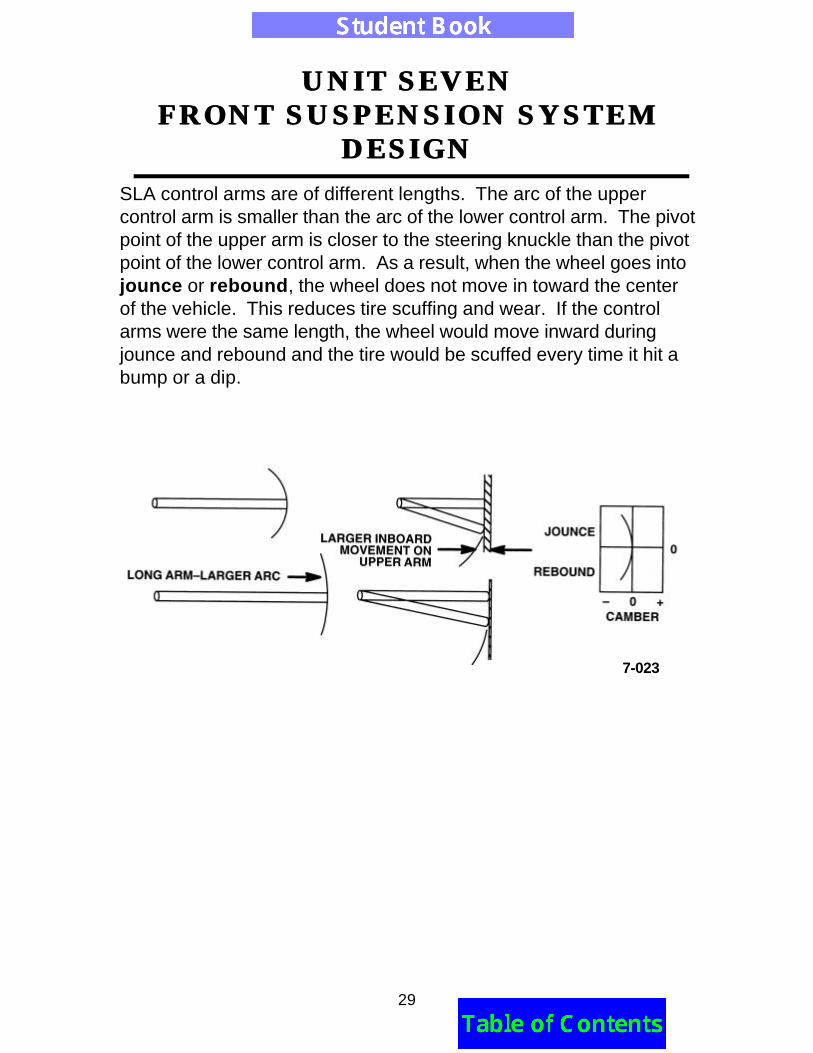
SLA control arms are of different lengths. The arc of the uppercontrol arm is smaller than the arc of the lower control arm. The pivotpoint of the upper arm is closer to the steering knuckle than the pivotpoint of the lower control arm. As a result, when the wheel goes intojounce or rebound, the wheel does not move in toward the centerof the vehicle. This reduces tire scuffing and wear. If the controlarms were the same length, the wheel would move inward duringjounce and rebound and the tire would be scuffed every time it hit abump or a dip.
7-023
UNIT SEVENUNIT SEVENFRONT SUSPENSION SYSTEMFRONT SUSPENSION SYSTEM
DESIGNDESIGN
30
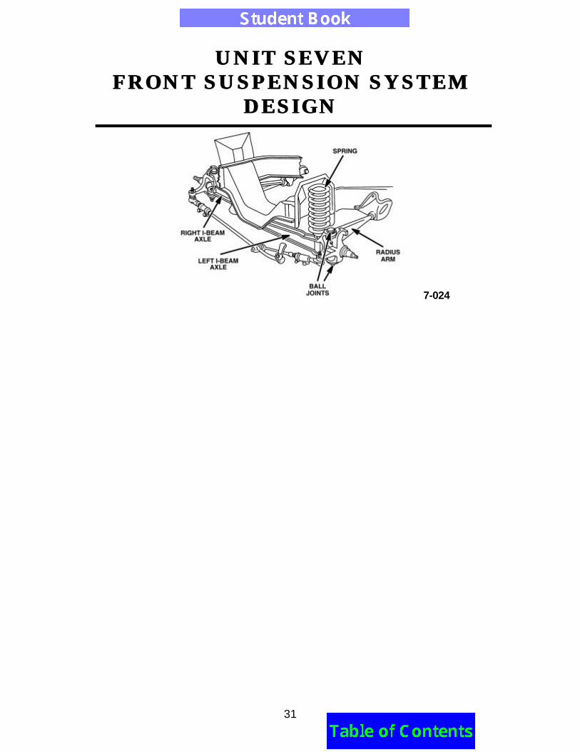
TWIN I-BEAM SUSPENSIONThe twin I-beam suspension is a combination of a solid axle and anindependent suspension system. It has the spindle and radius armconnected to the beam's outer end. The spindle is mounted withkingpins. The radius arm controls fore and aft movement of thewheel.
If the I-beam suspension uses leaf springs, no radius rods areneeded. The leaf springs control the fore and aft movements. Theinner end of the I-beam is mounted on the vehicle's frame railopposite the wheel it controls. The inner end of the I-beam connectsto a pivot bracket similar to a control arm.
The twin I-beam helps limit roll due to the leverage on the beam'spivot point during a turn, but does not produce a large camberchange. It does produce some side slip due to the length of thebeam, which limits the vehicle's handling ability as compared to mostother independent suspensions. The design is, however, verydurable. The twin I-beam can also be modified to handle four-wheeldrive vehicles. This suspension has better anti-roll and steeringability due to the beam's inner pivot point locations. During jounceand rebound, the twin I-beam causes camber changes.
UNIT SEVENUNIT SEVENFRONT SUSPENSION SYSTEMFRONT SUSPENSION SYSTEM
DESIGNDESIGN
31
7-024
UNIT SEVENUNIT SEVENFRONT SUSPENSION SYSTEMFRONT SUSPENSION SYSTEM
DESIGNDESIGN
32
TORSION BAR FRONT SUSPENSIONSYSTEMSTorsion bars are often used in place of leaf or coil type springs.They are mounted to the lower control arm in SLA suspensionsystems. The torsion bars can also be mounted to front and rearsuspensions that are in a trailing arm configuration. Torsion barsuspensions are mounted inline or transversely, depending onvehicle design. The torsion bar can also act as a lower control armstrut to eliminate fore and aft movement of the lower control arm.
The torsion bar suspension is often adjustable for curb height,eliminating spring replacement due to sagging or fatigue.
7-025
UNIT SEVENUNIT SEVENFRONT SUSPENSION SYSTEMFRONT SUSPENSION SYSTEM
DESIGNDESIGN
33
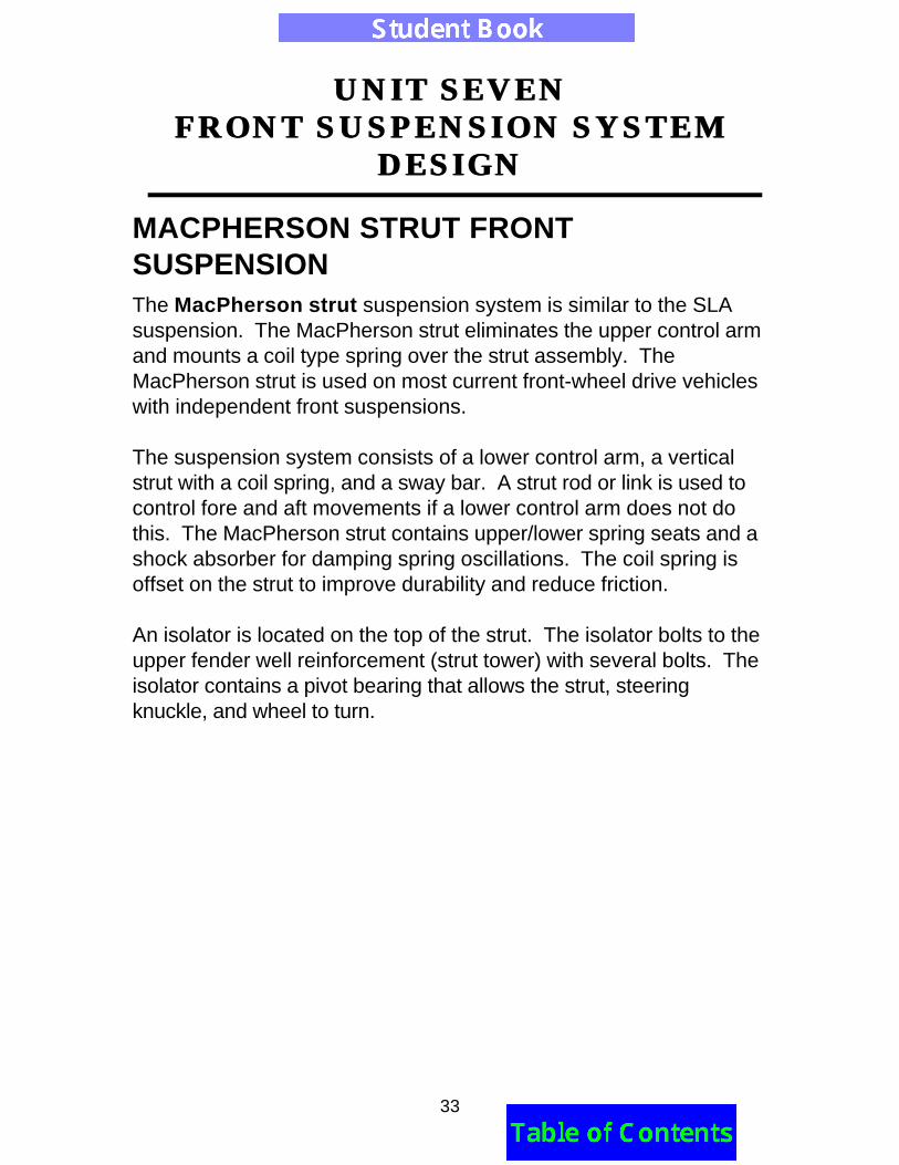
MACPHERSON STRUT FRONTSUSPENSIONThe MacPherson strut suspension system is similar to the SLAsuspension. The MacPherson strut eliminates the upper control armand mounts a coil type spring over the strut assembly. TheMacPherson strut is used on most current front-wheel drive vehicleswith independent front suspensions.
The suspension system consists of a lower control arm, a verticalstrut with a coil spring, and a sway bar. A strut rod or link is used tocontrol fore and aft movements if a lower control arm does not dothis. The MacPherson strut contains upper/lower spring seats and ashock absorber for damping spring oscillations. The coil spring isoffset on the strut to improve durability and reduce friction.
An isolator is located on the top of the strut. The isolator bolts to theupper fender well reinforcement (strut tower) with several bolts. Theisolator contains a pivot bearing that allows the strut, steeringknuckle, and wheel to turn.
UNIT SEVENUNIT SEVENFRONT SUSPENSION SYSTEMFRONT SUSPENSION SYSTEM
DESIGNDESIGN
34
7-026
UNIT SEVENUNIT SEVENFRONT SUSPENSION SYSTEMFRONT SUSPENSION SYSTEM
DESIGNDESIGN
35
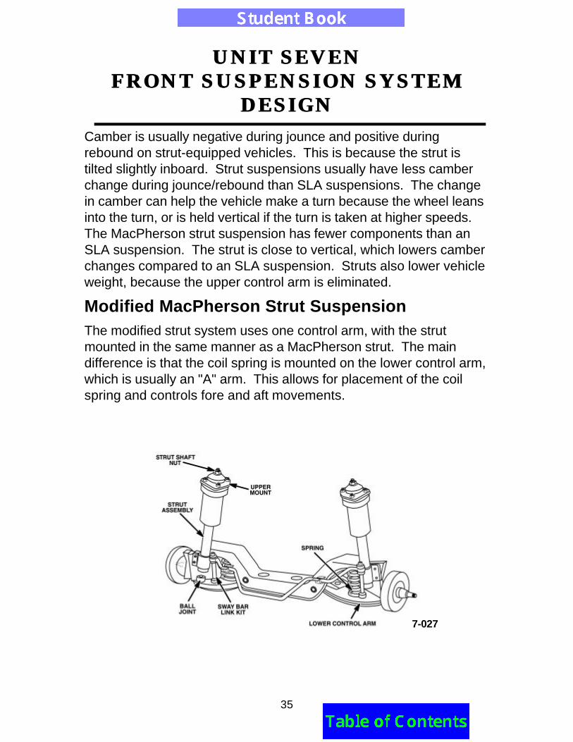
Camber is usually negative during jounce and positive duringrebound on strut-equipped vehicles. This is because the strut istilted slightly inboard. Strut suspensions usually have less camberchange during jounce/rebound than SLA suspensions. The changein camber can help the vehicle make a turn because the wheel leansinto the turn, or is held vertical if the turn is taken at higher speeds.The MacPherson strut suspension has fewer components than anSLA suspension. The strut is close to vertical, which lowers camberchanges compared to an SLA suspension. Struts also lower vehicleweight, because the upper control arm is eliminated.
Modified MacPherson Strut SuspensionThe modified strut system uses one control arm, with the strutmounted in the same manner as a MacPherson strut. The maindifference is that the coil spring is mounted on the lower control arm,which is usually an "A" arm. This allows for placement of the coilspring and controls fore and aft movements.
7-027
UNIT SEVENUNIT SEVENFRONT SUSPENSION SYSTEMFRONT SUSPENSION SYSTEM
DESIGNDESIGN
36
VARIABLE DAMPING SHOCKS OR STRUTSSome suspensions have shocks and struts with variable orificescalled variable damping shocks. The variable orifice controlsjounce and rebound rates. The settings are soft, normal and firm.The settings are sometimes controlled by electric motors, whichrotate the shock's internal piston to vary the orifice size. The orificesize is determined by the shutter valve location. As the shutter valveis turned, the shutter can open up a compression and reboundorifice allowing more oil flow and a softer ride. Orifice location canbe driver or computer controlled.
Air Shocks and StrutsAir shocks and struts are similar to air springs in that air pressure isused to dampen forces. In air shocks, a flexible air bladder ismounted between the shock piston rod and chassis attaching point.Air struts mount the bladder inside the upper portion of the strutassembly, below the pivot bearing and isolator. Both componentsprovide a means of adjusting damping force and improving ridequality.
7-028
UNIT SEVENUNIT SEVENFRONT SUSPENSION SYSTEMFRONT SUSPENSION SYSTEM
DESIGNDESIGN
37
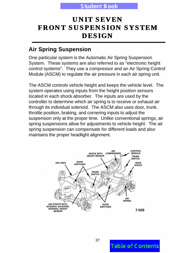
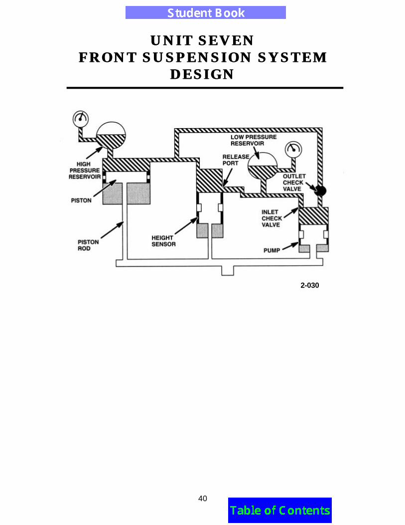
Air Spring SuspensionOne particular system is the Automatic Air Spring SuspensionSystem. These systems are also referred to as "electronic heightcontrol systems". They use a compressor and an Air Spring ControlModule (ASCM) to regulate the air pressure in each air spring unit.
The ASCM controls vehicle height and keeps the vehicle level. Thesystem operates using inputs from the height position sensorslocated in each shock absorber. The inputs are used by thecontroller to determine which air spring is to receive or exhaust airthrough its individual solenoid. The ASCM also uses door, trunk,throttle position, braking, and cornering inputs to adjust thesuspension only at the proper time. Unlike conventional springs, airspring suspensions allow for adjustments to vehicle height. The airspring suspension can compensate for different loads and alsomaintains the proper headlight alignment.
7-029
UNIT SEVENUNIT SEVENFRONT SUSPENSION SYSTEMFRONT SUSPENSION SYSTEM
DESIGNDESIGN
38
Load Leveling SuspensionAnother system that uses air shocks is the Automatic Air LoadLeveling System. This design uses air shocks to supplement thesuspension system when carrying heavy loads. The air shocks arelocated on the rear of the vehicle. A height sensor provides an inputto the system's control module regarding rear vehicle height.
When the control module determines that vehicle height is lower thanthe desired level (carrying a heavy load), it activates an aircompressor mounted under the vehicle. If the control moduledetermines the vehicle height is too high (load removed), it activatesa pressure release solenoid in the compressor, which releases airfrom the system. Using the air shocks, the rear vehicle height isautomatically adjusted.
UNIT SEVENUNIT SEVENFRONT SUSPENSION SYSTEMFRONT SUSPENSION SYSTEM
DESIGNDESIGN
39
Nivomat SuspensionAnother type of load leveling system is called Nivomat, which isGerman for "level automatically". The Nivomat System does not useair shocks or a compressor to adjust vehicle ride height. Instead,each rear shock absorber contains a hydraulic pump that pressurizesthe hydraulic charge inside the shock absorber. The hydraulicpressure acts upon the surface of the shock piston to raise vehicleheight. A valve, also internal to the shock, controls the pressure tomaintain the correct vehicle height.
The internal hydraulic pump is mechanically activated as the shockabsorber travels through jounce and rebound. When the shock isexperiencing light action, the pump strokes are short and thehydraulic flow is low. When the shock is experiencing heavy action,the pump strokes are longer and hydraulic flow increases. Sincepump operation is dependent on shock operation, the time ordistance traveled before the system is raised to ride height may varywith road conditions and the load carried. When the load isremoved, the system should return to ride height within a fewseconds.
UNIT SEVENUNIT SEVENFRONT SUSPENSION SYSTEMFRONT SUSPENSION SYSTEM
DESIGNDESIGN
40
2-030
UNIT SEVENUNIT SEVENFRONT SUSPENSION SYSTEMFRONT SUSPENSION SYSTEM
DESIGNDESIGN
41
LESSON THREELESSON THREEDESIGN AND FUNCTION OF WHEELDESIGN AND FUNCTION OF WHEEL
BEARINGSBEARINGS
TERMINAL OBJECTIVESuccessful completion of this Unit’s enabling objectives(technical competencies) will allow you to meet theIntegrated Curriculum Standards (ICS) listed in the rightmargin.
ENABLING OBJECTIVESUpon completion of Lesson Two, you should be able to:•
ICS
101Basic Physics
102Mechanics and Forces
155Steering andSuspension Systems
156Wheel Alignment,Wheels, and Tires
UNIT SEVENUNIT SEVENFRONT SUSPENSION SYSTEMFRONT SUSPENSION SYSTEM
DESIGNDESIGN
42
BEARINGS
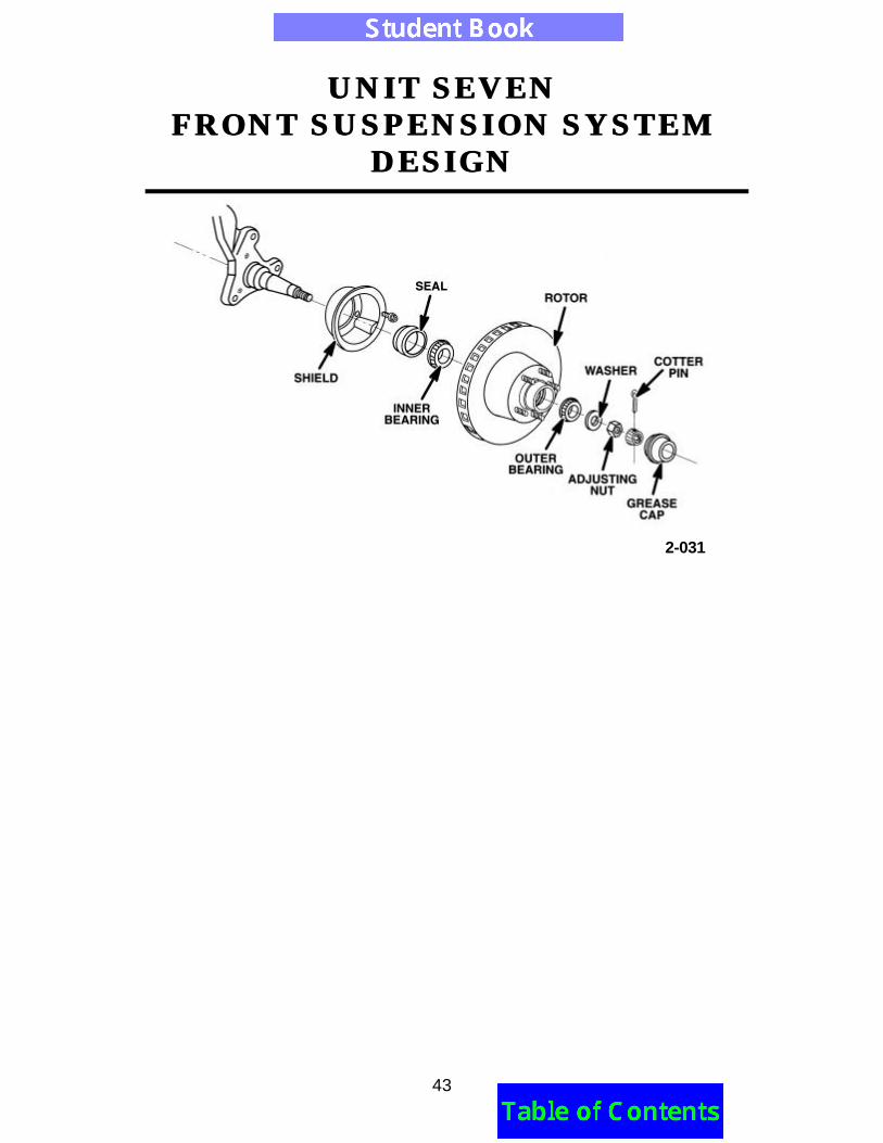
Tapered Roller BearingsAdjustable tapered roller bearings are found mainly on the frontspindles of rear-wheel drive vehicles such as light trucks, vans andolder cars. They are also found on the rear spindles of some frontwheel drive cars.
A tapered roller bearing consists of a cone assembly (inner race,tapered rollers, and a cage) which is mounted on the stationaryspindle. A cup, or outer race, is press fit into the rotating hub androtor assembly. The races and rollers carry the load while the cagekeeps the rollers evenly spaced. Two bearings, an inner and anouter, are used on each wheel. Both bearings require periodiclubrication and adjustment (preload) at specified service intervals.Refer to the Service Manual or Owner's Manual for service intervals.
Caution: Vehicle weight should not be allowed to rest onbearings unless the bearings have been properly torqued oradjusted (preloaded).
UNIT SEVENUNIT SEVENFRONT SUSPENSION SYSTEMFRONT SUSPENSION SYSTEM
DESIGNDESIGN
43
2-031
UNIT SEVENUNIT SEVENFRONT SUSPENSION SYSTEMFRONT SUSPENSION SYSTEM
DESIGNDESIGN
44
Bearing Cleaning and InspectionAdjustable tapered roller bearings must be cleaned at and repackedfor service at intervals specified in the Service Manual and Owner'sManual.
Before cleaning the bearings, examine the condition of the grease.A milky, white grease usually indicates that water has entered thebearing through the inner seal. A strong odor may indicate greaseoxidation due to high temperatures. Metal particles may indicate thata bearing is spalled.
Bearings should be cleaned in a parts tank with an approvedcleaning solvent. Be sure that there is proper ventilation andprotective clothing is worn. After cleaning, allow the bearings to drythoroughly. Use lint-free towels or allow the bearings to air dry.Excess solvent can be blown off with compressed air. When doingthis, direct the air stream from one end of the roller to the other whileholding the cage with your thumb.
Warning: Never spin a bearing with compressed air. The force ofthe compressed air may cause the rollers to be expelled from thecage at a high speed, possibly causing personal injury.
The bearing should be carefully inspected for damage aftercleaning. Inspect the bearings for corrosion, abrasive wear, signs ofoverheating, spalling, handling damage, brinelling, etc. Rotate therollers by hand to check for binding or a bent cage. Any bearingsthat show damage should be replaced with a new bearing. Alsoinspect the spindle and hub for burrs and wear, and replace asnecessary.
UNIT SEVENUNIT SEVENFRONT SUSPENSION SYSTEMFRONT SUSPENSION SYSTEM
DESIGNDESIGN
45
If one portion of the bearing assembly (the outer race, for example)is replaced, the mating assembly should also be replaced. The useof a damaged bearing could cause serious component damage orfailure.
New bearings are coated in a preservative. This preservative iscompatible with the wheel grease and does not need to be removedbefore installation. If a used bearing is being used again, it can beimmediately repacked with grease once the cleaning solvent hasdried. If the bearing is not repacked immediately after cleaning, itshould be coated in a light oil to protect against corrosion.
Bearings usually fail as the result of one of the following:• Ineffective sealing• Lack of lubrication• Defective bearing seats for inner and outer races• Incorrect shaft/housing fit• Misalignment of components• Vibrations when the bearing is not rotating
Bearing LubricationLubrication is critical to bearing life. Wheel bearings do not require alot of grease, but the grease must be constantly available. Lubricantshould be of the NLGI GC-LB type. Wheel bearings should neverhave different types of grease intermixed. Possible incompatibilitybetween lubricants could occur, causing thinning and lack oflubrication.
If lubrication is not supplied, even for a short period of time, abearing can become so hot that the rollers or balls weld to the race.Often the heat is enough to cause small particles to come off andweld to another location.
UNIT SEVENUNIT SEVENFRONT SUSPENSION SYSTEMFRONT SUSPENSION SYSTEM
DESIGNDESIGN
46
This is referred to as "smearing" or "scoring". In tapered rollerbearings, the first signs of inadequate or lack of lubrication appear asscoring on the large ends of the rollers. This soon progress intoheat discoloration on the large end of the rollers and races. Thelarge end of the rollers is the area of sliding contact within a taperedroller bearing, and thus, is the most difficult area to prevent scoring,especially when lubrication is not readily available. If operation underthese conditions continues, the damaged bearings eventually softenthe material, with the end result being bearing seizure othercomponent damage.
Bearings can also develop "peeling", which gives the races or rollersa frosty appearance. Peeling may indicate the presence of highoperating temperatures or low lubricant viscosity.
Bearings must be packed with appropriate grease (refer to theService Manual for specific applications). A mechanical bearingpacker is easiest, but hand packing is acceptable. When handpacking; force the grease into the bearing at the large end of therollers until the grease begins to come through the small end of therollers. With either method of packing, the important issue is to fullypack the bearing with grease.
Seal ReplacementYou should replace the inner seal along with the bearing (newlylubricated), to prevent leaks. Seals should always be cleaned andlubricated before reassembly, and replaced if torn or damaged.Seals are usually replaced when rotors are turned. Housings inwhich seals are installed must be clean to prevent misalignment.Most wheel bearing seals are of the lip design and are press fit withthe proper driver or arbor press to prevent misalignment anddamage.
UNIT SEVENUNIT SEVENFRONT SUSPENSION SYSTEMFRONT SUSPENSION SYSTEM
DESIGNDESIGN
47
Incorrect Component AlignmentOften bearings wear or become spalled due to improper componentalignment. This type of damage appears at the edges of the contactareas because they see abnormally high stress.
Misalignment is usually caused by worn or bent spindles, burrs onbacking shoulders or in housings (hubs). Wheel bearing settingsthat are too loose can also contribute to misalignment. Extremelyloose bearing settings also cause vibrations as the tire and wheelbounce over the road.
Bearing Adjustment (Preload)Proper wheel bearing adjustment is extremely important to operationand component life. The Service Manual should be referred to forspecific adjustment procedures on each vehicle. There are severaldifferent types of adjusting and locking mechanisms (cotter pins,keys, double jamb nuts, etc.) and each variation requires a uniqueadjustment procedure to obtain the correct bearing setting.
Perhaps the most used adjusting device on light vehicles is thesingle nut, retainer, and cotter pin mechanism. A typical adjustmentprocedure (refer to the Service Manual for specific procedures)consists of the following:
• Torque the adjusting nut to 10 - 20 ft. lbs. while rotating the hubto seat the bearing
• Back-off the nut until it is loose (approximately 1/2 turn)• Tighten the nut finger tight (10 - 20 in. lbs.)• Install retainer and cotter pin• With this setting, bearing end play should be approximately
.0003" - .005" end play
UNIT SEVENUNIT SEVENFRONT SUSPENSION SYSTEMFRONT SUSPENSION SYSTEM
DESIGNDESIGN
48
An alternate method is to torque the nut to 10 - 20 ft. lbs., then back-off the nut 1/6 to 1/4 turn and install the retainer and cotter pin.
Regardless of which method is used, almost all bearings should beset with a slight amount of endplay. Endplay provides a slightamount of clearance between the rollers and races to allow forexpansion due to heat during normal operation.
Bearing endplay measurements are taken with a dial indicator. Thedial indicator (with a magnetic base) is attached to the face of thehub and the indicator tip is positioned at the end of the spindle. Bypushing and turning the hub inward with approximately 40 - 60pounds of force, the inner bearing is seated.
Then, by pulling and twisting the hub outward, the outer bearing isseated. At this point, a direct outward force on the hub should beapplied and the dial indicator reading taken. Endplay is equal to thetotal amount of travel of the indicator.
UNIT SEVENUNIT SEVENFRONT SUSPENSION SYSTEMFRONT SUSPENSION SYSTEM
DESIGNDESIGN
49
GLOSSARY• Air Spring – A pneumatic spring which controls vehicle curb and
ride height.• Ball Joint – A component used to provide movement in two
planes: rotational and vertical. The joint is like the ball andsocket in one’s shoulder.
• Body Roll – Shifting of the vehicle body weight to one sideduring a turn.
• Bushing – A component which separates two othercomponents to allow for movement. Also cushions shocks andreduces friction.
• Coil Spring – A helical steel rod, wound in a special form. Thedistance between loops contracts and expands as a vehicleenters jounce and rebound.
• Control Arm – A suspension component used to contain lateraland fore/aft forces to maintain proper alignment of a vehicle.
• Dampening – Reducing movement or vibration such as a shockabsorber dampening a springs oscillation.
• Deflection Rate – Distance a spring bends under a given loador pressure.
• Jounce – The upward movement of a wheel from its normalposition, usually caused by a road bump or weight transfer ontothe wheel.
• Leaf Spring – Spring made from flat strips of spring steel.Usually strips are stacked one on top of another.
• Load Rating – A tire’s weight-carrying ability, usually indicatedon the tire sidewall.
UNIT SEVENUNIT SEVENFRONT SUSPENSION SYSTEMFRONT SUSPENSION SYSTEM
DESIGNDESIGN
50
• MacPherson Strut – A suspension component that uses a coilspring mounted around a shock absorber. The strut assemblyhas a bearing on top to allow steering movement. It is normallyattached between the upper end of the steering knuckle and astrut tower.
• Rebound – The downward motion of a wheel, such as when thetire enters a hole. Stored spring energy is released fromcompression due to the hole.
• Shock Absorber – A device placed at each vehicle wheel toregulate spring rebound and compression.
• Stabilizer Bar – A bar used to transfer weight from one side ofa vehicle to the other during turns. A torsion device which twistswhen a vehicle enters jounce and transfers the force to thevehicle’s rebounded wheel. Used to help maintain a level bodyin turns. Also referred to as an anti-sway or anti-roll bar.
• Steering Knuckle – A component used to allow rotationalsteering movement and to support the wheel. The knuckle hasan integral spindle and steering arm or a mount for the spindleand/or steering arm. The forging often serves as a mount for thetie rod, wheel bearing/hub unit and caliper.
• Torsion Bar – A spring steel bar which uses a torsion (torque ortwisting) resistance for spring action.
• Variable Damping Shocks – A shock absorber or strut whichhas multiple orifices to increase or decrease damping rates.